Abstract
Stimulated Brillouin scattering (SBS) lasers based on silicon waveguides with large SBS gain have been widely used in frequency tunable laser emissions, mode-locked pulse lasers, low-noise oscillators, optical gyroscopes and other fields. However, among SBS lasers, the realization of Brillouin laser output often requires a longer waveguide length, which not only increases waveguide loss but also increase the size of the device. As a new medium, lithium niobate has been fabricated into a new type of hybrid structure. Meanwhile, the width of a suspended waveguide is adjusted to tune the phonon frequency of an SBS laser based on lithium niobate substrate. Simulation results show that the tunable forward SBS effect is realized in a lithium niobate-suspended optical waveguide, showing a larger forward stimulated Brillouin scattering gain of 0.31 W−1m−1. The tunable phonon frequency ranges from 1 to 15 GHz. Therefore, utilizing the photon–phonon conversion effect, the waveguide system with LiNbO3 will pave a new way forward with better integration.
1. Introduction
The stimulated Brillouin scattering (SBS) effect is a third-order nonlinear effect, which is produced by the interaction of photons and phonons in a medium. Therefore, the SBS effect can be used to realize the interaction between acoustic waves and light waves. Since the last century, SBS has been widely used in many optical fields, such as slow light, signal processing technology, sensors and filters [1,2,3,4,5]. Many micro-devices and nano-scale materials have been used to enhance the SBS effect in various respects, including sub-wavelength diameter fibers [6]. In 2013, Kabakova. Irina V et al. demonstrated, for the first time, a narrow linewidth Brillouin laser based on a chalcogenide photonic chip [7]. In 2015, Raphaël Van Laer and others designed a partially suspended Si nanowire waveguide, which achieved a sound field frequency of 9.4 GHz. The forward SBS gain coefficient of the Si nanowire waveguide measured in the experiment reached 3218 W−1m−1. However, the waveguide length of the model needs to reach the order of cm, which is not easy to integrate. At the same time, due to the high hardness of silicon, it is difficult for sound waves to be guided in a silicon-on-insulator (SOI) waveguide [8]. Therefore, the interaction between phonons and photons is suppressed, thereby affecting the SBS effect. In order to stimulate a strong photon–phonon interaction in SOI, this paper proposes the use of lithium niobate instead of silicon, which can capture light and sound waves. Lithium niobate-on-insulator (LNOI) has a strong optical field limitation. In recent years, it has been widely used in the field of integrated photonics, especially in high-efficiency nonlinear frequency converters [9]. Its refractive index is 2.237, and its photonics tensor is p11 = −0.026, p12 = 0.07, p44 = −0.71. Compared with traditional silicon materials, LN crystals have excellent material characteristics, such as a low loss transparent window, a high electro-optic coefficient and a high second-order non-linearity, and have been widely used in many aspects [10,11]. Periodically polarized lithium niobate (PPLN) crystals and diffusion waveguides, in which the ferroelectric domain of lithium niobate can be accurately phase-matched due to its periodic flipping characteristics, have been used in many fields [12,13,14,15,16]. At the same time, a layer of air is added to the periphery of lithium niobate; in this way, the photonic effect (PE) can be further enhanced to further increase the Brillouin gain coefficient [8]. However, the acoustic index contrast of the upper layer of the air/LiNiO3 boundary is much higher than the acoustic index contrast at the bottom of the LiNiO3/SiO2 boundary, which causes the sound field in the proposed structure to be distributed upward. Therefore, this limits the photo–acoustic coupling effect and makes the Brillouin gain coefficient lower. Thus far, has been necessary to propose a more complete design scheme, especially in terms of a highly integrated and tunable on-chip Brillouin laser.
The traditional fiber-optic waveguide has a very poor confinement effect on the lateral sound field, which is why the general fiber-optic waveguide can only observe the BSBS. Therefore, in order to realize FSBS, the structure of the waveguide must be specially designed so that it can restrict the optical field and the lateral sound field at the same time. The suspended structure uses the high acoustic contrast of the solid–air interface to limit the acoustic mode [10], so that the lateral sound field mode can be confined in the waveguide medium, meaning that the sound field has a long enough time to fully interact with the light field. Therefore, in this paper, we designed a suspended waveguide for forward stimulated Brillouin scattering (FSBS), in which the coupled light field is coupled in different optical spatial modes, and compared it with the gain of backward Brillouin scattering (BSBS). This process is similar to FSBS. The difference between them lies in whether the direction of the Stokes light and the incident light generated by the pump light is the same or the opposite; this is generated by BSBS, the discovery of the Stokes light being contrary to the pump light and the direction of the sound field vibration produced by it is axial. Its waveguide length is 5 µm. The tuning of the phonon frequency of 1–15 GHz is realized through examining the width of the suspended waveguide, and it exhibits a large forward SBS gain. In addition, the waveguide system has better integration, using photon–phonon conversion, which opens up a new route for the mixing of physics and photonics, CMOS and micro-electromechanical systems.
2. Materials and Methods
The forward stimulated Brillouin scattering (FSBS) waveguide represents a direct interaction between pump light, Stokes light or anti-Stokes light and sound waves [12,13]. Its basic physical mechanism is shown in Figure 1: a pump with frequency ωp and Stokes light with frequency ωs are coupled into the waveguide in the same direction to generate a beat signal.
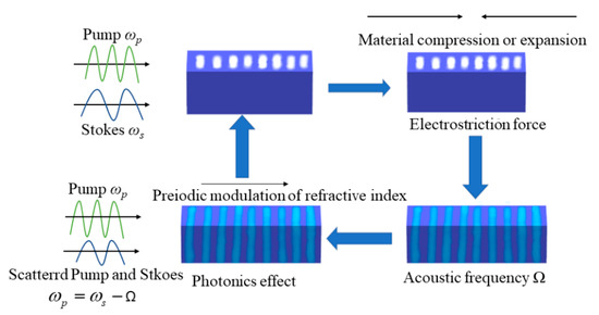
Figure 1.
FSBS effect in the waveguide.
When the pump light propagates along the waveguide, a photonics effect will occur on the surface of the waveguide, which will generate an electrostriction force. In the meantime, the dielectric constant in the waveguide will also change, resulting in a periodically modulated refractive index [12,13,14]. The Stokes light and phonons produced by FSBS propagate in the same direction as the pump light, and the vibration direction of the sound field is lateral. More specifically, in the FSBS process, the light field propagates in the same direction, and the propagation direction of the phonons and the propagation direction of the light field during the scattering process are perpendicular to each other [17,18]. In the SBS process, the phase-matching condition should be met, i.e., the conservation of energy and momentum should meet the following conditions:
where , and are the phonon wave vector, pump wave vector and Stokes wave vector, respectively. Given the propagation direction of the Stokes wave, SBS can be divided into backward stimulated Brillouin scattering (BSBS) and forward stimulated Brillouin scattering (FSBS).
For the FSBS process, we assume that the propagation directions of pump light and Stokes light are both along the z-axis, so the light wave field of pump light and Stokes light can be described as:
where is the pump light field and is the Stokes light field. Using small signal approximation, assuming that the pump power in the waveguide is greater than the Stokes signal power, the coupling between the pump light and the Stokes signal light should meet the following requirements [18],
where Pp and Ps are the power of the pump light and Stokes light, respectively, is the linear loss of the light wave and and are the nonlinear loss coefficient caused by two-photon absorption and the non-linear loss coefficient caused by free carrier absorption, respectively. In Equation (7), g(Ω) is the SBS gain coefficient, which can be expressed by the Lorentz model as follows [19]:
where is the eigenfrequency satisfied by the um eigenequation of the acoustic mode without considering the acoustic loss; is the sound film loss coefficient when sound loss is included [1], which depends on the light quality factor , and shall comply with the following relationship: [20], where the subscript m is the m-order acoustic mode (m = 1, 2, 3…) [1].
When considering the sound loss, each SBS gain coefficient can be simplified to [20]:
where , and are the light group velocity, conductivity and density, respectively; f is the sum of the optical forces of pump light and Stokes light. It is assumed that and integrally covers the entire waveguide cross-sectional area. It is the overlap integral between the total optical [21] force and a single m-order optical eigenmode, and it represents the optical–mechanical coupling strength based on the suspended waveguide [22].
Both electrostrictive force and radiation pressure in the nanoscale waveguide contribute to the Brillouin gain, and the f in Formula (9) represents the total optical force (radiation pressure and electrostrictive force). In the ideal acoustic equation, when there is no driving force, the acoustic displacement um can be obtained. Therefore, the finite element algorithm is used to simulate the pump light and Stokes light field distribution and the light force field distribution at a given frequency. Then, we simulate the displacement field distribution of the elastic sound field mode that satisfies the Brillouin phase-matching condition. Finally, the FSBS gain coefficient of the waveguide can be ascertained by calculating the overlap integral between the optical force field and the acoustic displacement field.
3. Results
Based on the formulas derived above, in this article, we designed a lithium niobate-suspended waveguide to measure the SBS gain that could be achieved when LN crystal is used as the medium, using COMSOL to study the inter-mode SBS effect, as shown in Figure 2c. The schematic diagram of the suspended waveguide system structure is shown in Figure 2a. Since we chose silicon dioxide as the substrate, and we exposed most of the lithium niobate to the outer air surface, few parts were in contact with the silicon dioxide substrate. The refractive index between the two materials is relatively large. The light field enhancement is located in the LN. Due to the high acoustic contrast of the lithium niobate–air interface, phonon vibration is restricted to the solid material. The general process of SBS is shown in Figure 2c (2): SBS is the interaction of light and phonons in the waveguide and is divided into FSBS and BSBS. In the process of the forward SBS effect, the strong restraint on light waves and elastic waves also increases the disturbing effects of the PE effect and the moving boundary (MB) effect [12]. This disturbance mainly comes from the Stokes (or anti-Stokes) signal scattered by the incident pump light. Therefore, when the pump light becomes larger, the electrostrictive force generated becomes larger and larger, and so has a considerable influence on Brillouin gain. This is determined by the electrostrictive force [16].
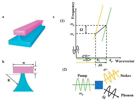
Figure 2.
(a) Schematic diagram of the suspended waveguide system; (b) Design drawing of suspended waveguide; t = 230 nm, w = 1.5 μm, SiO2 radius corresponds to R = 762.5 nm; (c) (1) Schematic diagram of the optical dispersion diagram. Optical resonance is represented by discrete points (red and blue) along the overall dispersion curve (solid line). In the figure, ks and kp represent the wave vectors of stoke light and pump light, respectively. ωs, ωp and Ω represent Stokes light, pump light and generated phonon frequencies, respectively. (2) Schematic diagram of the conversion of pump light to Stokes light and phonons.
The selected waveguide width was w = 1.5 μm, t = 230 nm and ring radius R = 762.5 nm. Under this condition, the gain of the forward SBS is shown in Figure 3.
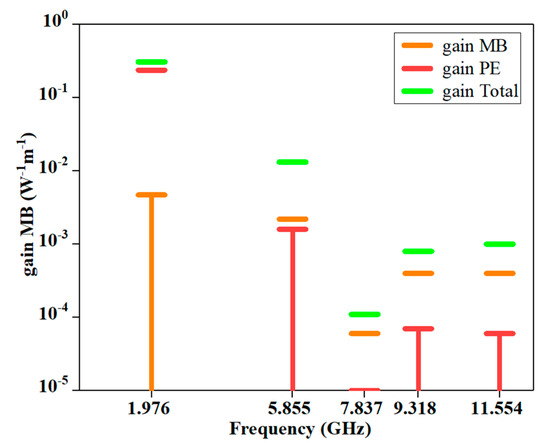
Figure 3.
Contribution of different effects to the FSBS gain coefficient in the stimulated Brillouin scattering process, including the MB effect (orange short line), radiation pressure effect (red short line) and the entire Brillouin contribution of gain (short green line, when the waveguide width w = 1500 nm.
Similar to the process of forward SBS, a hybrid waveguide model is also designed, and the waveguide width is selected as w = 2.818 μm, t = 230 nm and ring radius R = 1417 nm. Since the characteristic frequency Ω generated by phonons is very small and can be ignored compared with the frequency ω of pump light, pump and Stokes light can be regarded as the same waveguide mode [15]. Under this condition, the BSBS gain diagram obtained is shown in Figure 4.
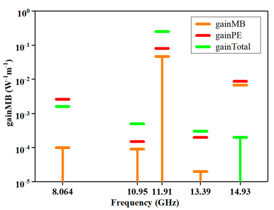
Figure 4.
Contribution of different effects to the BSBS gain coefficient in the stimulated Brillouin scattering process, including the moving boundary effect (orange short line), radiation pressure effect (red short line) and the entire Brillouin contribution of gain (short green line) when the waveguide width w = 2818 nm.
By comparing the gain data of FSBS and BSBS above, it can be concluded that the Brillouin gain in BSBS can reach 0.249 W−1m−1, and the FSBS gain can reach 0.31 W−1m−1. FSBS achieved a higher gain, so it can be concluded that the effect of forward SBS is better than that of backward SBS, which also provides a direction for future experiments. The following is a detailed discussion on the forward SBS.
When pump light and Stokes light enter the waveguide, the interaction between the two produces greater electrostrictive force and radiation pressure. Under the action of these two forces, the sound field mode will be excited in order to produce phonons. Additionally, phonons can also propagate in the waveguide, and this process is the photon–phonon coupling process. When pump light, Stokes light and phonons satisfy the conservation of energy and momentum, strong acoustic–optic coupling and FSBS effects will occur. When the waveguide width is w = 1.5 µm, the electric field distribution generated by the pump light is shown in Figure 5a, and Figure 5b shows the finite element simulation of the acoustic–optic coupling rate changing with waveguide width. The red dotted star line represents the relationships between frequencies in the acoustic wave models and waveguide width of each mode order m, utilizing , in which Vl = 6570 m/s represents the speed of sound in lithium niobate and m represents the integer of the mode order. Figure 5c represents the five acoustic modes (m = 1, 2, 3, 4, 5) produced when the waveguide width is 1.5 µm under the action of the MB effect and the PE effect, as shown in Figure 5b. The five red dotted star lines correspond to each other. It can be seen from Figure 5c that the first-order acoustic breathing mode and the TE optical mode have better photomechanical coupling efficiency; in this case, the maximum strain component overlaps the optical mode to the same extent. Therefore, we obtained a higher acoustic–optic coupling efficiency, as shown in Figure 5b.
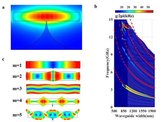
Figure 5.
Based on forward Brillouin scattering: (a) the electric field distribution diagram of pump light, waveguide width w = 1.5 µm; (b) The finite element simulation of the photoacoustic coupling rate varies with the width of the waveguide in the suspended waveguide structure. The red dotted star line is the frequency calculated by satisfying the Fabry–Perot multi-order mode. The formula Ωp = mVl/(2w) can be approximated for simulation, where Vl = 6570 m/s; (c) When the waveguide width is 1.5 µm, the mode distribution diagram of the phonon mode determined in b that meets each phase-matching is determined.
On the other hand, when used for coupling between a third-order acoustic mode and surrounding TE modes, there is competition between the PE effect and the MB effect. The product of the boundary and the volume is opposite to the geometric phase, resulting in a self-cancellation effect. In addition, in the forward scattering state, a simple suspended waveguide is not enough to completely confine the elastic phonon wave within the waveguide.
It can be seen from Figure 6 that each waveguide produces a series of regular Brillouin resonances [23]. As shown in Figure 5c, due to the light field having spatial symmetry, only phonons with uniform spatial symmetry can produce effective Brillouin coupling [24]. As the size of the waveguide changes, the colored curves in Figure 6 represent different resonance characteristics. As shown in Figure 3, the change in the size of the suspended waveguide achieves 1–15 GHz frequency resonance, as well as nonlinear tunability.
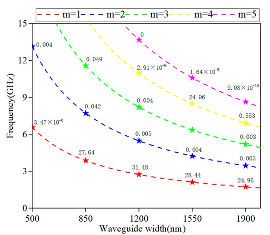
Figure 6.
The relationship between the coupling efficiency of the Brillouin-suspended laser and the frequency change with the waveguide width. Where m represents the order of the acoustic mode, the number in the table represents the coupling efficiency and its unit is kHz.
4. Conclusions
In this paper, a new type of hybrid photon–phonon waveguide system is designed by using a new inorganic material, lithium niobate, as the propagation medium, and the tuning of the SBS sound field signal frequency is achieved by adjusting the width of the waveguide. According to the PE effect and the MB effect, the gain of the suspended structure SBS laser reaches 0.31 W−1m−1, and the high SBS gain excites higher-power phonons, realizing the non-uniformity of the sound field with a signal frequency of 1–15 GHz given its linear class tuning characteristics. Therefore, this suspended waveguide width tuning solution can realize the photon–phonon conversion based on the Brillouin nonlinear effect, and can guide and manipulate phonons emitted by the Brillouin on the chip. Therefore, the Brillouin device can provide an opportunity for the mixing of physics and photonics, CMOS and MEMS.
Author Contributions
Conceptualization, W.W. and Y.Y.; methodology, Y.L. (Yunfei Li) and G.W.; software, W.W.; validation, W.W., Y.Y. and Y.L. (Yunfei Li); formal analysis, G.W., Z.W., C.S. and K.L.; investigation, W.W.; resources, Z.L., Y.W. and Z.B.; data curation, Y.Y.; writing—original draft preparation, W.W. and Y.Y.; writing—review and editing, W.W. and Y.Y.; visualization, S.L., Y.L. (Yuhai Li), T.L. and X.Y.; supervision, Y.Y.; project administration, Y.Y.; funding acquisition, Y.L. (Yuhai Li), T.L., X.Y. and Y.Y. All authors have read and agreed to the published version of the manuscript.
Funding
This work was supported by the National Natural Science Foundation of China (Grant No. 62005074, No. 61927815, No. 62075056, and No. 62004059) and Key Laboratory Fund Project (No. 61421070302).
Institutional Review Board Statement
Not applicable.
Informed Consent Statement
Not applicable.
Data Availability Statement
Not applicable.
Conflicts of Interest
The authors declare no conflict of interest.
References
- Lang, Z.; Yuangang, L.; Yangyang, F.; Haixia, M.; Chaolin, D. Design of a hybrid on-chip waveguide with giant backward stimulated Brillouin scattering. Opt. Express 2019, 27, 24953. [Google Scholar]
- Eggleton, B.J.; Poulton, C.G.; Rakich, P.T.; Steel, M.J.; Bahl, G. Brillouin integrated photonics. Nat. Photonics 2019, 13, 664–677. [Google Scholar] [CrossRef]
- Liu, Y.; Choudhary, A.; Marpaung, D.; Eggleton, B.J. Integrated microwave photonic filters. Adv. Opt. Photonics 2020, 12, 485–555. [Google Scholar] [CrossRef]
- Bai, Z.; Williams, R.J.; Kitzler, O.; Sarang, S.; Spence, D.J.; Wang, Y.; Lu, Z.; Mildren, R.P. Diamond Brillouin laser in the visible. APL photonics 2020, 5, 031301. [Google Scholar] [CrossRef]
- Bai, Z.; Yuan, H.; Liu, Z.; Xu, P.; Gao, Q.; Williams, R.J.; Kitzler, O.; Mildren, R.P.; Wang, Y.; Lu, Z. Stimulated Brillouin scattering materials, experimental design and applications: A review. Opt. Mater. 2018, 75, 626–645. [Google Scholar] [CrossRef]
- Florez, O.; Jarschel, P.F.; Espinel, Y.; Cordeiro, C.; Alegre, T.M.; Wiederhecker, G.S.; Dainese, P. Brillouin scattering self-cancellation. Nat. Commun. 2016, 7, 11759. [Google Scholar] [CrossRef] [PubMed] [Green Version]
- Kabakova, I.V.; Pant, R.; Choi, D.Y.; Debbarma, S.; Luther-Davies, B.; Madden, S.J.; Eggleton, B.J. Narrow linewidth Brillouin laser based on chalcogenide photonic chip. Opt. Lett. 2013, 38, 3208–3211. [Google Scholar] [CrossRef] [PubMed] [Green Version]
- Jouybari, S.N. Brillouin gain enhancement in nano-scale photonic waveguide. Photonics Nanostruct. Fundam. Appl. 2018, 29, 8–14. [Google Scholar] [CrossRef]
- Niu, Y.; Lin, C.; Liu, X.; Chen, Y.; Zhu, S. Optimizing the efficiency of a periodically poled lnoi waveguide using in situ monitoring of the ferroelectric domains. Appl. Phys. Lett. 2020, 116, 101104. [Google Scholar] [CrossRef]
- Poulton, C.G.; Pant, R.; Eggleton, B.J. Acoustic confinement and Stimulated Brillouin Scattering in integrated optical waveguides. J. Opt. Soc. Am. B Opt. Phys. 2013, 30, 2657–2664. [Google Scholar] [CrossRef]
- Wong, K.-K. Properties of Lithium Niobate; INSPEC/IEE: London, UK, 2002; p. 28. [Google Scholar]
- Parameswaran, K.R.; Route, R.K.; Kurz, J.R.; Roussev, R.V.; Fejer, M.M.; Fujimura, M. Highly efficient second-harmonic generation in buried waveguides formed by annealed and reverse proton exchange in periodically poled lithium niobate. Opt. Lett. 2002, 27, 179–181. [Google Scholar] [CrossRef] [PubMed] [Green Version]
- Miller, G.D.; Batchko, R.G.; Tulloch, W.M.; Fejer, M.M.; Byer, R.L. 42%-efficient single-pass cw second-harmonic generation in periodically poled lithium niobate. Opt. Lett. 1997, 22, 1834–1836. [Google Scholar] [CrossRef] [PubMed]
- Tanzilli, S.; Tittel, W.; Riedmatten, H.D.; Zbinden, H.; Baldi, P.; Demicheli, M.; Ostrowsky, D.; Gisin, N. PPLN waveguide for quantum communication. Eur. Phys. J. D 2002, 18, 155–160. [Google Scholar] [CrossRef] [Green Version]
- Langrock, C.; Diamanti, E.; Roussev, R.V.; Yamamoto, Y.; Fejer, M.M.; Takesue, H. Highly efficient single-photon detection at communication wavelengths by use of upconversion in reverse-proton-exchanged periodically poled LiNbO3waveguides. Opt. Lett. 2005, 30, 1725–1727. [Google Scholar] [CrossRef] [PubMed]
- Tanzilli, S.; Tittel, W.; Halder, M.; Alibart, O.; Baldi, P.; Gisin, N.; Zbinden, H. A photonic quantum information interface. Nature 2005, 437, 116–120. [Google Scholar] [CrossRef] [PubMed]
- Damzen, M.J.; Vlad, V.I.; Babin, V.; Mocofanescu, A. Stimulated Brillouin Scattering: Fundamentals and Applications; CRC Press: Boca Raton, FL, USA, 2010; pp. 26–27. [Google Scholar]
- Mirnaziry, S.R.; Wolff, C.; Steel, M.J.; Eggleton, B.J.; Poulton, C.G. Stimulated Brillouin scattering in silicon/chalcogenide slot waveguides. Opt. Express 2016, 24, 4786. [Google Scholar] [CrossRef] [PubMed]
- Agrawal, G.P. Nonlinear Fiber Optics; Academic Press: Cambridge, MA, USA, 2007; pp. 355–383. [Google Scholar]
- Qiu, W.; Rakich, P.T.; Shin, H.; Dong, H.; Soljačić, M.; Wang, Z. Stimulated Brillouin scattering in nanoscale silicon step-index waveguides: A general framework of selection rules and calculating SBS gain. Opt. Express 2013, 21, 31402–31419. [Google Scholar] [CrossRef] [PubMed] [Green Version]
- Aryanfar, I.; Wolff, C.; Steel, M.J.; Eggleton, B.J.; Poulton, C.G. Mode conversion using stimulated Brillouin scattering in nanophotonic silicon waveguides. Opt. Express 2014, 22, 29270–29282. [Google Scholar] [CrossRef] [PubMed] [Green Version]
- Yu, Z.; Sun, X. Giant enhancement of stimulated Brillouin scattering with engineered phoxonic crystal waveguides. Opt. Express 2018, 26, 1255–1267. [Google Scholar] [CrossRef] [PubMed]
- Shin, H.; Qiu, W.; Jarecki, R.; Cox, J.A.; Iii, R.; Starbuck, A.; Zheng, W.; Rakich, P.T. Tailorable stimulated Brillouin scattering in nanoscale silicon waveguides. Nat. Commun. 2013, 4, 1944. [Google Scholar] [CrossRef] [PubMed] [Green Version]
- Peter, T.R.; Cox, J.A.; Shin, H.; Zheng, W.; Potter, R.C. Traveling-wave photon-phonon coupling as the basis for new signal processing technologies. In Proceedings of the SPIE Defense and Security Symposium, Baltimore, MD, USA, 5–9 May 2014. [Google Scholar] [CrossRef]
Publisher’s Note: MDPI stays neutral with regard to jurisdictional claims in published maps and institutional affiliations. |
© 2021 by the authors. Licensee MDPI, Basel, Switzerland. This article is an open access article distributed under the terms and conditions of the Creative Commons Attribution (CC BY) license (https://creativecommons.org/licenses/by/4.0/).