Article

The Influence of Permeability on the Propagation Characteristics of the Waves in Different Saturated Soils

1
College of Civil Engineering, North China University of Technology, Beijing 100144, China
2
The Key Laboratory of Urban Security and Disaster Engineering of Ministry of Education, Beijing University of Technology, Beijing 100124, China
*
Author to whom correspondence should be addressed.
Appl. Sci. 2021, 11(17), 8138; https://doi.org/10.3390/app11178138
Submission received: 23 June 2021 / Revised: 25 August 2021 / Accepted: 27 August 2021 / Published: 2 September 2021
(This article belongs to the Section Civil Engineering)

Abstract

:
The permeability of saturated soils has great influence on the velocities and attenuation characteristics of fast compressional wave P1, low compressional wave P2, and shear wave S in saturated soils, respectively. In three different cases, namely zero, finite, and infinite permeability, the wave equations and theoretical velocities of P1, P2, and S wave in saturated soils are given based on the u-w-p equation, respectively. According to the solutions of the wave equations, the real velocities and attenuation coefficients of three waves are redefined, respectively. In different saturated soils, the influences of the permeability and the loading frequency on the wave velocities and attenuation are discussed, respectively. Moreover, the suitable application scope of the u-p equation is discussed based on different permeabilities and loading frequencies.

1. Introduction

Saturated soils are a saturated porous medium consisting of a solid skeleton and pore water. Because of the different materials and the fluid–solid couplings, the propagation characteristics of waves in saturated soils are different from those of single-phase soils. For engineering involving the dynamic problems of saturated soils, such as petroleum engineering, geophysics, earthquake engineering and the seabed acoustics etc. [1,2], the analysis of the wave theory of saturated soils is employed to provide guidance and reference.
Biot first constructed the wave theory of saturated porous medium in the 1950s, namely the Biot theory [3,4]. However, the Biot theory is uncomprehensive due to the abstract concepts of several parameters in the controlling equation, and the parameters are difficult to assign; therefore, many scholars further developed the Biot theory [5,6,7,8]. Zienkiewicz proposed the dynamic u-w-p equation, which has a clear physical concept by ignoring the added mass density and introducing the dynamic of permeability to replace fluid viscosity. Moreover, the u-p formulation [9,10] is the simplified form of the u-w-p equation and is widely applied due to its simple equation and high computational efficiency. However, because of the simplified assumption of ignoring the acceleration of the fluid phase relative to the solid phase, the u-p equation is limited in solving dynamic problems under low or medium frequency loadings.
Biot [3] successfully predicted that there are three body waves (two compressional waves, the P1 and P2 waves, and one shear wave, the S wave) in saturated soils, and acquired the velocity of each wave. He stated that the interaction between solid and fluid phases in saturated soils consists of inertia, mechanical, and viscous couplings [3,4,11,12]. The inertia and mechanical couplings are the main reasons for the generation of the three body waves, and the propagation of waves in saturated soils is attenuated and dispersed due to the viscous coupling. Moreover, the existences of the three waves in saturated soils were confirmed by many experiments. Plona [13] used a model of glass balls submerged in water to simulate saturated porous media, which imposed a high frequency loading. He successfully verified the existence of the three waves in saturated porous media for the first time. Rasolofoason [14] and Nagy et al. [15] separately conducted similar experiments on actual saturated sands and gravels. They observed the slow compressional wave, P2 wave, in saturated soils as well. Berryman [16] tested the velocities of the three waves in saturated porous media through experiments. The velocities were in a good agreement with the theory velocities of the Biot theory. In fact, the propagation of the three waves in saturated soils showed regularity. The P1 wave propagates in both of the solid and fluid phases with the same velocity because of the compressibility of the saturated porous medium [17]. The diffusion process of the fluid in the voids of the solid skeleton generates the P2 wave. The velocity of the P1 wave is faster than the velocity of the P2 wave. The two waves show amplitude attenuation during the propagation procedure. Moreover, the strong viscous coupling in saturated soils with a low permeability [12] or under a low frequency loading makes the velocity of the P2 wave attenuate to zero rapidly [3]. For the S wave, because a pore fluid cannot carry a shear force, the S wave only propagates in the solid skeleton and the propagation characteristics are only dependent on the shear strength of the solid skeleton.
Present research on wave propagation behaviors in saturated soils mainly focus on the velocities, frequency dispersion, velocity attenuation characteristics, etc. In addition, the effect of the physical parameters, such as the loading frequency and permeability, on the wave propagation characteristics are analyzed [18]. Berryman [19] analyzed the wave attenuation characteristics in saturated porous media under the earthquakes. Schmitt [20], and Sharma and Gogna [21] researched wave propagation characteristics in transverse isotropy saturated porous media, respectively. Zhou and Lai [22] established the relations of wave propagation characteristics, attenuation characteristics, and porosity in frozen soils. In addition, the propagation characteristics of saturated soils based on the assumption of an uncompressed solid skeleton were studied [23,24,25,26]. Dutta [27] acquired the velocities of two compressional waves in saturated porous media using the analytical method, and the velocities had good agreement with those measured from experiments [13]. Li and Song [28] obtained the velocities of two compressional waves under extreme permeability (zero and infinite). Kim et al. [29,30] analyzed the influence of the pore path, porosity, and the volume modulus of the solid skeleton on the propagation characteristics of the P1 and P2 wave. Yang et al. [31] systematically introduced the relations of parameters, such as porosity, permeability, and fluid viscosity, and the wave propagation characteristics of saturated soils. The typical generalized frequency dispersion curves and attenuation curves of the three waves were obtained. Steeb et al. [32] established dynamic models of three-phase porous media to research the propagation characteristics of unsaturated soils. The results showed that the fluid phase had a great influence on the frequency dispersion and attenuation characteristics of unsaturated soils, whether under loadings or not. Han et al. [33] showed that the frequency dispersion and attenuation characteristics of two compressional waves are not only dependent on the range of the loading frequency, but are also are remarkably affected by the permeability of saturated soils.
The works mentioned above cannot reflect the effect of permeability on wave propagation characteristics. Moreover, most research on wave propagation properties only focus on one certain saturated soil. The analyses of comparisons between different saturated soils are rare. For the u-p equation, analyses exist that summarize the suitable scope of application with two dimensionless parameters only in one-dimensional soil, and the physical meanings of the two dimensionless parameters are ambiguous. In this paper, for zero, finite, and infinite permeability, the wave equations and velocities of P1, P2, and S waves in saturated soils are acquired, respectively. Based on the solutions of the wave equations, the actual velocities and attenuation coefficients are redefined. Moreover, wave propagation characteristics are compared in saturated soils with different permeabilities. In the end, the suitable scope of the u-p formulation is discussed according to the contrasts of the wave velocities obtained from the u-p and u-w-p formulations.

2. Equations of Saturated Soils

Saturated soils are regarded as a two-phase medium consisting of a solid skeleton and the pore fluid in the voids of the solid skeleton. The pore fluid and the interaction between the two phases make the mechanical properties of saturated soils very different from one-phase soils. Therefore, two governing equations describing the mechanical properties of saturated soils are determined.

2.1. u-w-p Formulation

The u-w-p formulation is a complete equation of saturated porous media. It consists of the basic governing equations, shown as follows:
(1)
Mass conservation equation of the pore fluid:
T w = 1 Q b p + α T u
(2)
Dynamic equilibrium equations:
σ = ρ u ¨ + ρ f w ¨
p = n ρ f u ¨ + ρ f w ¨ + k f 1 w ˙
(3)
Effective stress principle:
σ = σ α m p
where the definitions of the symbols used in Equations (1)–(4) are listed in Table 1. Equations (1)–(4) consist of the basic governing equations of saturated porous media.
Equations (1) and (4) are substituted into Equations (2) and (3) and the u-w-p formulation is expressed by displacement and the pore pressure variables can be written as follows:
( λ + G ) u + G 2 u α p ρ u ¨ ρ f w ¨ = 0
α T u ˙ T k ¯ p + 1 Q b p ˙ ρ f k ¯ T u ¨ ρ f n k ¯ T w ¨ = 0

2.2. u-p Formulation

Zienkiewicz [10] assumed that the relative acceleration of the fluid phase can be ignored as the relative motion between the fluid and solid phases are slow. By ignoring the terms of the fluid acceleration in the u-w-p formulation, the simplified u-p formulation can be written as:
{ ( λ + G ) u + G 2 u α p ρ u ¨ = 0 α T u ˙ T k ¯ p + 1 Q b p ˙ = 0
where the definitions of the symbols in Equation (7) are listed in Table 1. The simplified u-p formulation has simpler equations and a higher computational efficiency relative to the u-w-p formulation. However, the assumption [10] limits the scope of application of the u-p formulation, which will be discussed in Section 6.

3. Wave Equations and Theoretical Wave Velocities

The pore fluid makes the propagation properties of the waves in saturated soils different from those of common soils, especially under dynamic loadings. The propagation procedures of the waves in saturated soils are closely related to the viscous coupling, so the seepage procedure of the pore fluid affects the velocities and the attenuation of the waves in saturated soils. Therefore, analysis of the propagation theory of saturated soils is necessary. In this section, for three different viscous couplings (finite, infinite, and zero permeability), the u-w-p formulation is transformed into three wave equations for the P1, P2 and S waves, and the corresponding theoretical velocities are obtained.

3.1. Finite Permeability

Using Fourier transform, the form of Equation (5) in the frequency domain can be written as:
( λ + G ) u + G 2 u + ω 2 ( ρ ρ f 2 ρ m ) u ( α ρ f ρ m ) p = 0
2 p + ω 2 ρ m Q b p ω 2 ( ρ f α ρ m ) u = 0
where ρm is introduced to make the formulation similar to the wave equations and has the relation of: ρ m = ρ f n 1 k ¯ i ω .
Displacement u and pore pressure p are decomposed by Helmholtz decomposition:
u = φ s + × ψ s   e
p = Q b ( α 2 φ s + 2 φ f )
where φ s and φ f are the irrotational potential function of the solid and fluid phases, respectively. ψ s is the rotational potential function of the solid phase. Substituting Equations (10) and (11) into Equations (8) and (9), and using the relation of ψ s e = 0 , the following equations can be obtained:
{ [ ( λ + 2 G + α 2 Q b α ρ f ρ m Q b ) 2 φ s + ( α ρ f ρ m ) Q b 2 φ f + ω 2 ( ρ ρ f 2 ρ m ) φ s ] + × [ G 2 ψ s + ω 2 ( ρ ρ f 2 ρ m ) ψ s ] e = 0 2 [ α Q b 2 φ s + Q b 2 φ f + ω 2 ( ρ f φ s + ρ m φ f ) ] = 0
φs, φf and ψs in Equation (12) should satisfy the following relations:
( λ + 2 G + α 2 Q b α ρ f ρ m Q b ) 2 φ s + ( α ρ f ρ m ) Q b 2 φ f + ω 2 ( ρ ρ f 2 ρ m ) φ s = 0
α Q b 2 φ s + Q b 2 φ f + ω 2 ( ρ f φ s + ρ m φ f ) = 0
ω 2 ( ρ ρ f 2 ρ m ) ψ s + G 2 ψ s = 0
Equations (13)–(15) can be expressed as three scalar equations and is written into the matrix forms shown below:
[ M ω 2 + K P 2 ] φ = 0
[ ( ρ ρ f 2 ρ m ) ω 2 + G 2 ] ψ s = 0
where,
φ = [ φ s φ f ] ,   M = [ ρ ρ f 2 ρ m 0 ρ f ρ m ] ,   K P = [ λ + 2 G + α 2 Q b α ρ f ρ m Q b ( α ρ f ρ m ) Q b α Q b Q b ]

3.1.1. Compressional Wave

The characteristic equation of the Equation (16) is:
| K P l P 2 M ω 2 | = 0
The dispersion equation can be obtained by unfolding Equation (19):
( λ + 2 G ) Q b ( l P ω ) 4 [ ( λ + 2 G + α 2 Q b ) ρ m 2 α Q b ρ f + Q b ρ ] ( l P ω ) 2 + ( ρ ρ m ρ f 2 ) = 0
The solution of Equation (20) is:
( l P 1 , 2 ω ) 2 = ( 1 C P 1 , 2 ) 2 = ρ 1 , 2 λ + 2 G
where,
ρ 1 , 2 = ρ ( b b 2 a c ) a = λ + 2 G Q b b = 1 2 ρ ( ρ 2 α ρ f + λ + 2 G + α 2 Q b Q b ρ m ) c = ρ m ρ ( ρ f ρ ) 2
Equation (21) is two complex solutions of Equation (20), respectively, where wave numbers lP1,2 and wave velocities CP1,2 are the theoretical wave numbers and velocities of two compressional waves in saturated soils, respectively. P1 and P2 represent the fast and low compressional waves in saturated soils, respectively.
In addition, the simplifier form can be written as below, by substituting Equation (14) into Equation (13)
( λ + 2 G ) 2 φ s ω 2 ( α ρ f ρ ) φ s ω 2 ( α ρ m ρ f ) φ f = 0
The potential functions of the solid and fluid displacements are, respectively, expressed by the potential functions of the P1 and P2 waves [34]
{ φ s = φ P 1 + φ P 2 φ f = η 1 φ P 1 + η 2 φ P 2
where,
η 1 , 2 = α Q b ρ f C P 1 , 2 2 Q b ρ m C P 1 , 2 2
Substituting Equation (24) into Equation (23) and using Equation (20), we can obtain the following equations:
{ C P 1 2 2 φ P 1 + ω 2 φ P 1 = 0 C P 2 2 2 φ P 2 + ω 2 φ P 2 = 0
Equation (26) is obtained as follows using the Fourier inverse transform:
{ C P 1 2 2 φ P 1 = φ ¨ P 1 C P 2 2 2 φ P 2 = φ ¨ P 2
In Equation (27), the equations of the potential functions of the P1 and P2 waves have the forms of wave equations.

3.1.2. Shear Wave

Similarly, Equation (17) of the rotational potential function ψ s is transformed into the time domain:
C S 2 2 ψ s = ψ ¨ s
where CS is the theoretical velocity of the shear wave (S wave). Equation (28) is the wave equation of the S wave and its characteristic equation is:
| G l S 2 ( ρ ρ f 2 ρ m ) ω 2 | = 0
The solution of Equation (29) is expressed as:
( l S ω ) 2 = ( 1 C S ) 2 = ρ ρ m ρ f 2 ρ m G
where lS is the theoretical wave number of the S wave.

3.2. Infinite Permeability

For the case of infinite permeability, the pore fluid flow through the solid porosity without any obstacle and there is no viscous coupling between the pore fluid and the solid skeleton in saturated soils. The properties of saturated soils are similar to the single-phase soils. In Equations (8) and (9), the permeability is set to k = and the relation ρ m ρ f / n is satisfied. Substituting the relation of k = , Equations (8) and (9) is transformed into:
( λ + G ) u + G 2 u + ω 2 ( ρ n ρ f ) u ( α n ) p = 0
2 p + ω 2 ρ f n Q b p ω 2 ( ρ f α n ρ f ) u = 0
Using the similar derivational process of the case of the finite permeability, the wave numbers and velocities of P1, P2, and S waves in infinite permeability cases, respectively, are:
{ ( l P 1 , 2 ( k = ) ω ) 2 = ( 1 C P 1 , 2 ( k = ) ) 2 = ρ 1 , 2 ( k = ) λ + 2 G ( l S ( k = ) ω ) 2 = ( 1 C S ( k = ) ) 2 = ( 1 n ) ρ s G
where,
ρ 1 , 2 ( k = ) = ρ ( b b 2 a c ) a = λ + 2 G Q b b = 1 2 ρ ( ρ 2 α ρ f + λ + 2 G + α 2 Q b Q b ρ f n ) c = ρ f n ρ ( ρ f ρ ) 2
From Equation (33), we can see that there are two compressional waves and one shear wave in saturated soils in the case of infinite permeability. The forms of the wave equations of P1, P2 and S waves are same with Equations (27) and (28).

3.3. Zero Permeability

For the case of zero permeability, there is no relative motion between the pore fluid and the solid skeleton. The strong viscous coupling makes the P2 wave attenuate to zero rapidly. Because w is equal to zero, the fluid relative velocity w ˙ and acceleration w ¨ are equal to zero, and the terms of permeability in Equations (5) and (6) are ignored. Equations (5) and (6) is simplified as:
( λ + G ) u + G 2 u α p ρ u ¨ = 0
α T u ˙ + 1 Q b p ˙ = 0
Referring to the method in the literature [35], Equation (36) is substituted into Equation (35). Two uncoupled equations about only the displacements are shown below:
{ ρ 2 u r t 2 = ( λ + 2 G + α 2 Q b ) ( 2 u r r 2 + 1 r u r r u r r 2 ) ρ 2 u θ t 2 = G ( 2 u θ r 2 + 1 r u θ r u θ r 2 )
In two dimensional cylindrical coordinates, the displacement potential functions, respectively, are expressed by the radial and tangential components:
{ u r = φ r u θ = ψ r
Equation (38) is substituted into Equation (37), and the wave equations of the displacement potential functions are obtained:
2 φ t 2 = C P 1 2 ( 2 φ r 2 + 1 r φ r )
2 ψ t 2 = C S 2 ( 2 ψ r 2 + 1 r ψ r )
where the velocities of P1 and S waves, respectively, are:
{ C P 1 = λ + 2 G + α 2 Q b ρ C S = G ρ
Equation (39) and Equation (40), respectively, are the wave equations of P1 and S waves under the zero-permeability condition.

4. Solutions of Wave Equations

In saturated soils with different permeabilities, all of the equations to describe the dynamic behaviors of the three body waves have the forms of wave equations. In this section, the solutions of the wave equations are determined in the forms of plane, cylindrical, and spherical waves.

4.1. Plane Wave

For the one-dimensional plane wave, the solutions of the potential functions of three waves are expressed as below [36]:
{ φ P 1 = A 1 exp ( i ( l P 1 x + ω t ) ) φ P 2 = A 2 exp ( i ( l P 2 x + ω t ) ) ψ S = A 3 exp ( i ( l S x + ω t ) )
where A1, A2 and A3 are the amplitudes of the P1, P2, and S waves, respectively. ω is circular frequency, x is the direction of wave propagation, and t represents time.

4.2. Cylindrical and Spherical Waves

For cylindrical and spherical waves, the solutions of the potential functions of the three waves are approximately expressed in Equations (43) and (44) [37], respectively
φ P 1 , 2 = 1 r f ( r C P 1 , 2 t ) ,   ψ S = 1 r f ( r C S t )
where f is random function of outgoing waves. P1 and P2 waves have the same wave functions, f. r is the radial direction of the wave propagation. However, different from the one-dimensional plane wave, the cylindrical and spherical waves have geometric attenuation during the diffusion process.

5. Discussions of Wave Velocities, Dispersion and Attenuation Characteristics

In the cases of infinite and zero permeability, the theoretical velocities in Equations (33) and (41) of the three body waves are all real numbers and independent of circular frequency. This indicates that the three waves have constant velocities and the propagation procedures are not attenuated and dispersed. For zero permeability, the density of the mixture medium is used to compute the velocity of the shear wave. Both of the solid and fluid phases undertake the shear force. For infinite permeability, only the density of the solid phase is used to compute the velocity of the shear wave. So, the saturated soil can be treated as a one-phase soil and the shear force is only undertaken by the solid skeleton.
For the finite permeability, the relation of ρ m = ρ f n 1 k ¯ i ω is used in Equations (21) and (30). The theoretical velocities of three waves are complex numbers, which are functions of the permeability and the circular frequency. Therefore, the propagation properties of the three waves in saturated soils are analyzed from the three aspects of dispersion, velocity, and attenuation characteristics, respectively.

5.1. Dispersion and Real Wave Velocity

Dispersion is a procedure where waves are gradually separated with different frequencies. Thus, the wave velocity, initial waveform, and vibration mode are changed during the propagation process.
In the case of the finite permeability, theoretical velocities of the three waves are uniformly expressed by the complex number C. Thus, the velocity can be written in the following form:
C j ( ω ) = ω l j ( ω ) = C r j ( ω ) + C i j ( ω ) i
where j is the root of the dispersion equation. J = 1, 2, 3. Cr and Ci represent the real and imaginary parts of the root, respectively. In Equation (36), real and imaginary parts of the velocity are expressed as a function of the circle frequency, which reflects the dispersion of the waves.
The one-dimensional plane wave is employed to simplify the analysis progress. Equation (42) is uniformly written as the form shown below:
φ j = A j exp ( i ω ( 1 C j ( ω ) x + t ) )
where,
1 C j ( ω ) = C r j ( ω ) C r j ( ω ) 2 + C i j ( ω ) 2 C i j ( ω ) C r j ( ω ) 2 + C i j ( ω ) 2 i
Equation (47) is substituted into Equation (46), and the following equation is obtained:
φ j = A j exp ( ω C ˜ i j ( ω ) x ) exp [ i ω ( 1 C ˜ r j ( ω ) x + t ) ]
where,
C ˜ i j ( ω ) = C r j ( ω ) 2 + C i j ( ω ) 2 C i j ( ω )
C ˜ r j ( ω ) = C r j ( ω ) 2 + C i j ( ω ) 2 C r j ( ω )
For the problems of a one-dimensional plane wave, the potential functions of three waves in a saturated porous medium can be expressed in a unified form of Equation (48). In Equation (48), the term A j exp ( ω C ˜ i j ( ω ) x ) describes the attenuation of the wave propagation, and the term exp [ i ω ( 1 C ˜ r j ( ω ) x + t ) ] reflects the propagation of the waves in a simple harmonic mode. Therefore, the real part of Equation (50) is the real wave velocity for the finite permeability case in a saturated porous medium.

5.2. Attenuation Coefficient

In the case of finite permeability, the velocity has an imaginary part, which illustrates that waves are attenuated in the propagation procedure.
Similarly, the potential function in Equation (48) can be expressed as an equivalent function of wave number l.
φ j = A j exp ( l i j ( ω ) x ) exp [ ( l r j ( ω ) x + ω t ) i ]
where the lr and li are the real and imaginary parts of the wave numbers, respectively. The wave number is l j ( ω ) = l r j ( ω ) + l i j ( ω ) i . The term of exp [ ( l r x + ω t ) i ] represents the mode of wave in the propagation procedure, and the amplitude of A exp ( l i x ) reflects that the amplitude of the wave attenuates in the exponential form.
The attenuation of the velocity can be described by the attenuation coefficient β, which is defined that the ratio of the reduction of the amplitude after a wavelength and the amplitude in a wavelength. The detailed formulation is shown as Equation (52)
β j = 1 exp ( l i j ( ω ) L ) = 1 exp ( l i j ( ω ) 2 π l r j ( ω ) )
where L is the wavelength in a period. The amplitude attenuation coefficient is a value between zero and one (0 < β < 1). The calculation of wave number l refers to Equations (21) and (30).

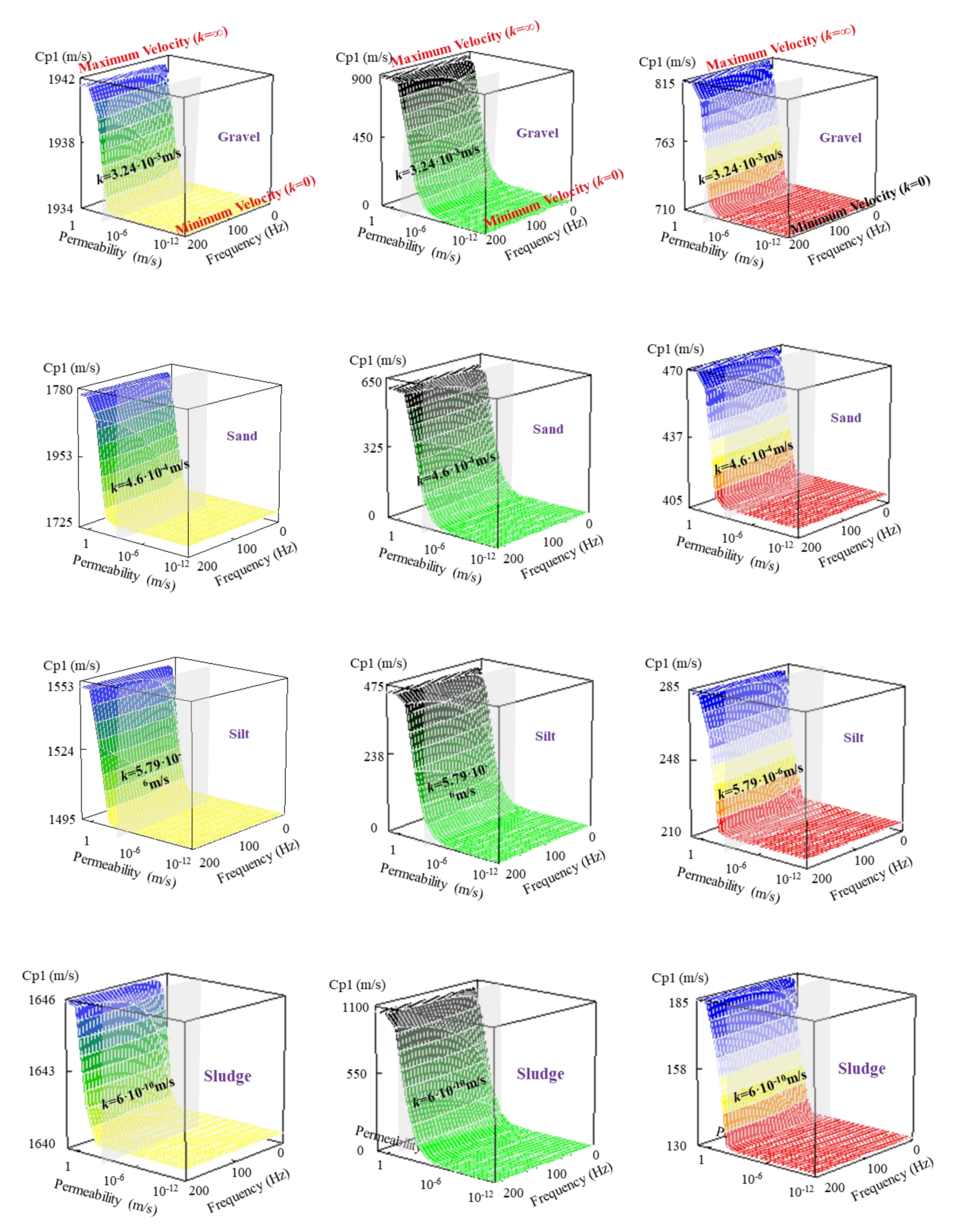
5.3. Comparison of Velocities and Frequency Dispersion in Different Saturated Soils

Four saturated porous medium, saturated gravel soil, sand soil, clay silt, and silt, were selected to analyze propagation characteristics. The mechanical parameters are listed in detail in Table 2.
Figure 1 shows the relation of the frequency, permeability, and velocities of the P1, P2, and S waves in the case of finite permeability. From Figure 1, as the permeability k < 1 × 10⁻⁶ m/s, the velocities of the three waves do not change with the increase in permeability and loading frequency. The values always maintain the minimum value, which is close to the minimum velocity under the condition of zero permeability. As the permeability k > 1 × 10⁻⁶ m/s, with the increase in permeability, the velocities of the three waves increase gradually to their maximum velocities, which are close to the velocities in the condition of infinite permeability. As the permeability is in the range of k < 1 × 10⁻⁶ m/s, the velocities of the three waves increase with the increase in the loading frequency. This indicates that the three waves are dispersed in the propagation procedure. Moreover, the permeability is proportional to the velocities, and the influence of loading frequency on the velocities is less than the permeability.
In Figure 1, by contrasting the relations of permeability, loading frequency, and the velocities in the four saturated soils, we can see that different saturated soils do not change the shapes of the velocity curves, but vary the amplitudes of the curves. The harder the soil, the faster the propagation wave is. The permeability coefficients of the grey planes in Figure 1 represent the actual permeability coefficients of the four saturated soils. They are k = 3.24 × 10⁻³, 4.6 × 10⁻⁴, 7.9 × 10⁻⁶ and 6 × 10⁻¹⁰ m/s, respectively. For the saturated soils with low permeability, such as clay silt and silt, the permeability coefficients are less than 1 × 10⁻⁶ m/s. The corresponding velocities are close to the minimum velocities and do not change with the loading frequency. Therefore, the minimum wave velocities can be used to replace the actual wave velocities in this condition. For the saturated soils with a high permeability, such as sand and gravel, the velocities fall in between the maximum and minimum velocities. The velocities of the three waves should be calculated by the actual velocity equations in this condition.

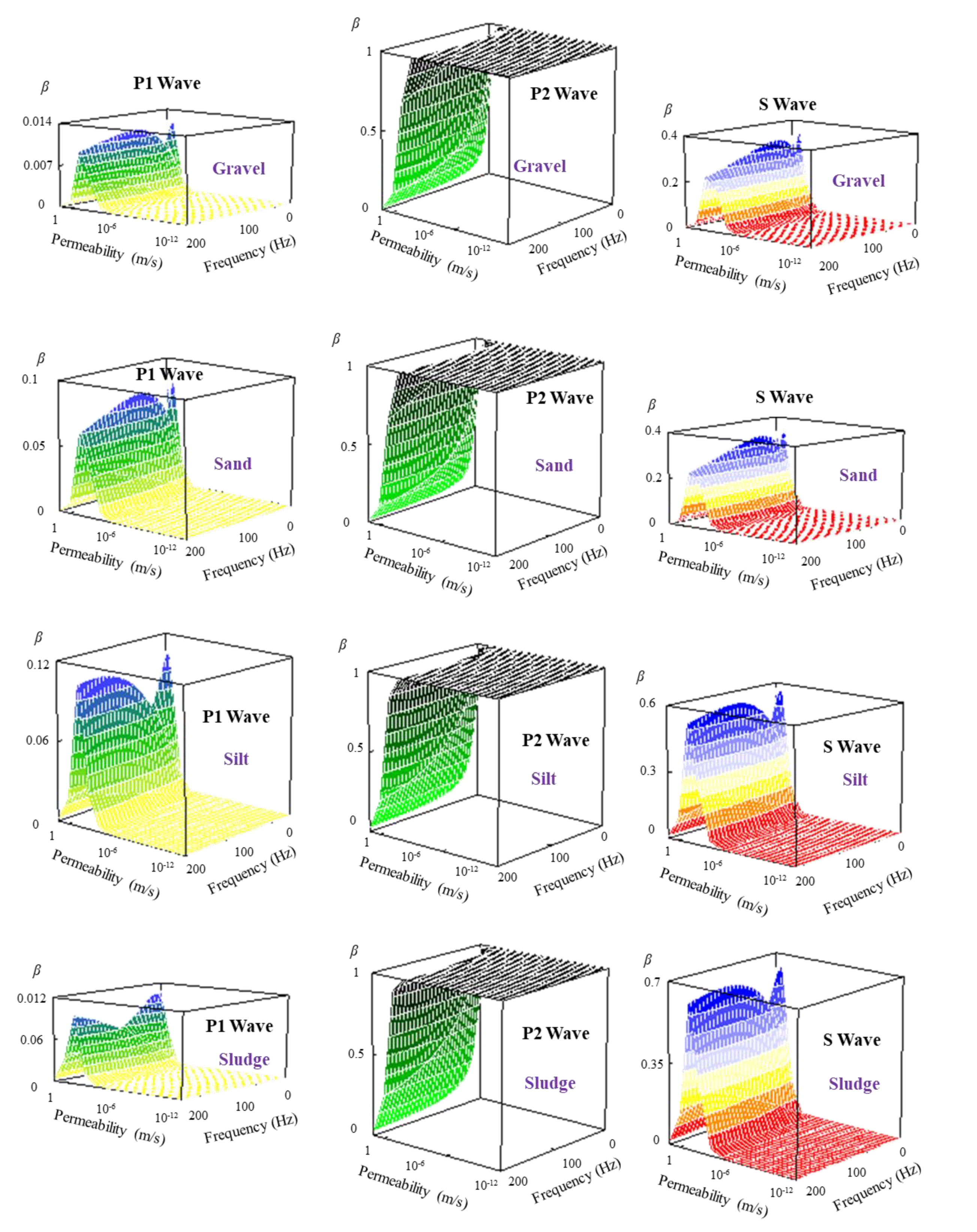
5.4. Comparison of Attenuation Coefficients in Different Saturated Soils

Figure 2 shows the relations of permeability, loading frequency, and the attenuation coefficients of the P1, P2, and S waves in the case of finite permeability. For P1 and S waves, as the permeability reaches k < 1 × 10⁻⁴ m/s the attenuation coefficients always remain at zero, which illustrates that the two waves do not attenuate in the propagation procedure. With the increase in the permeability, a wave crest appears in the range of k > 1 × 10⁻⁴ − 1 m/s and the maximum values of the attenuation coefficients appear as permeability is about 1 × 10⁻² m/s for the P1 and S waves. This indicates that two waves show slight attenuation. For the P2 wave, as permeability k > 1 × 10⁻⁴ m/s, the attenuation coefficients change from 1.0 to 0.0 with the increase of the permeability. The P2 wave gradually attenuates to zero. Contrasted with the loading frequency, the permeability has more influence on the attenuation coefficient.
Comparing the relations of permeability, loading frequency, and the attenuation coefficient in the four saturated soils, we can find that different saturated soils do not change the shapes of the attenuation coefficient curves, but do change the amplitudes of these curves. Especially when the saturated soils changed from the gravel to the silt, the amplitudes of the attenuation coefficients of the S wave obviously shows an increased tendency. The S wave attenuates more significantly in soft soils.

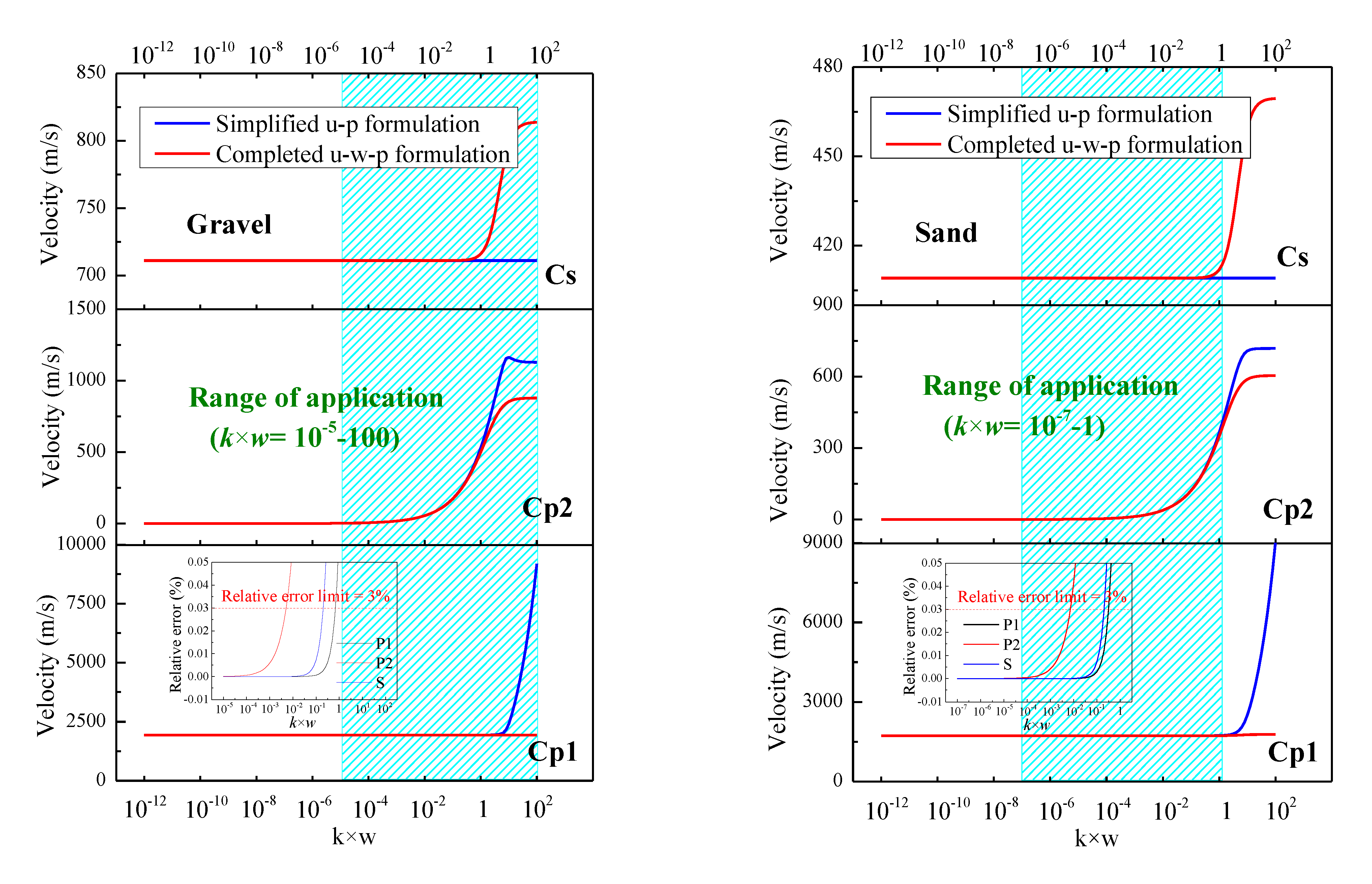
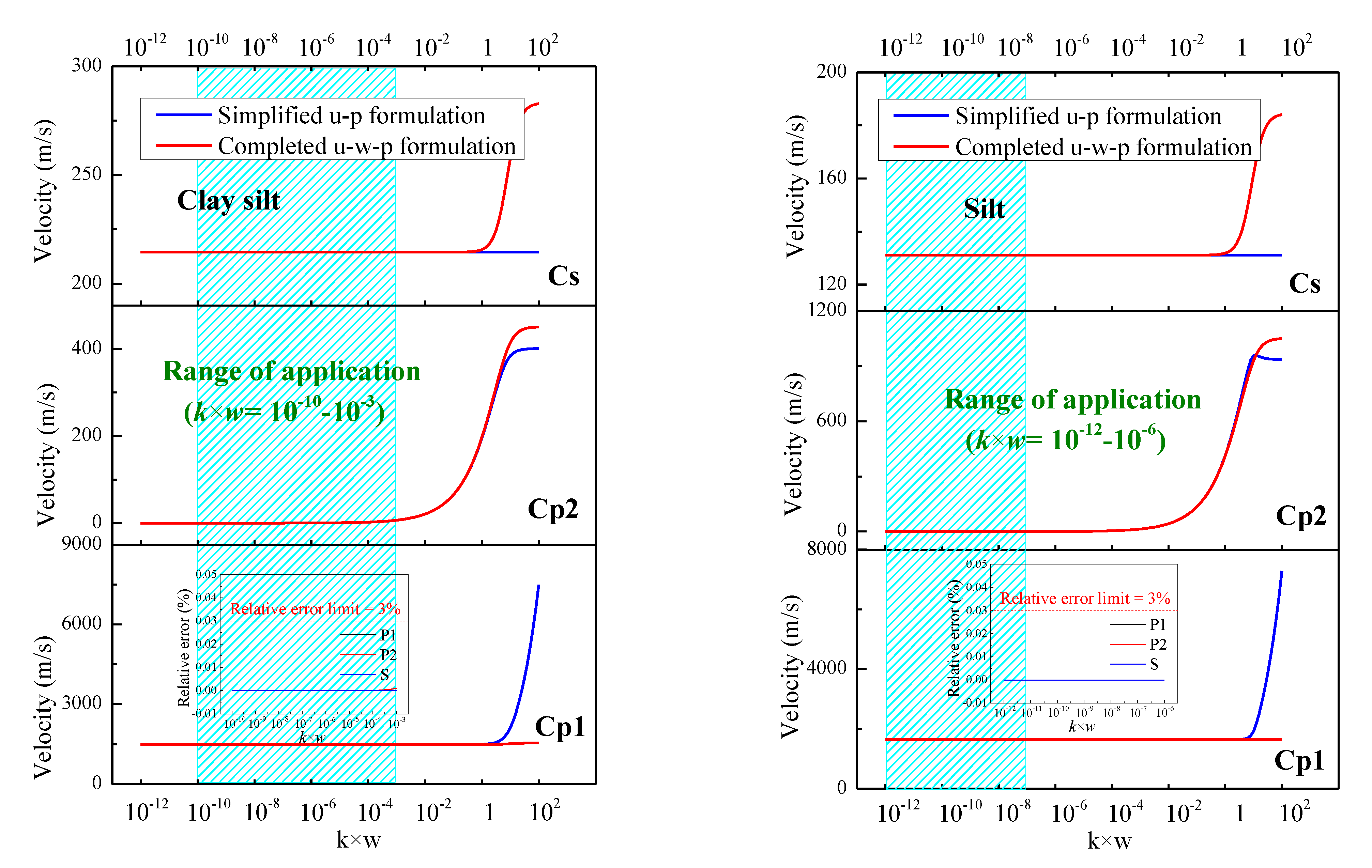
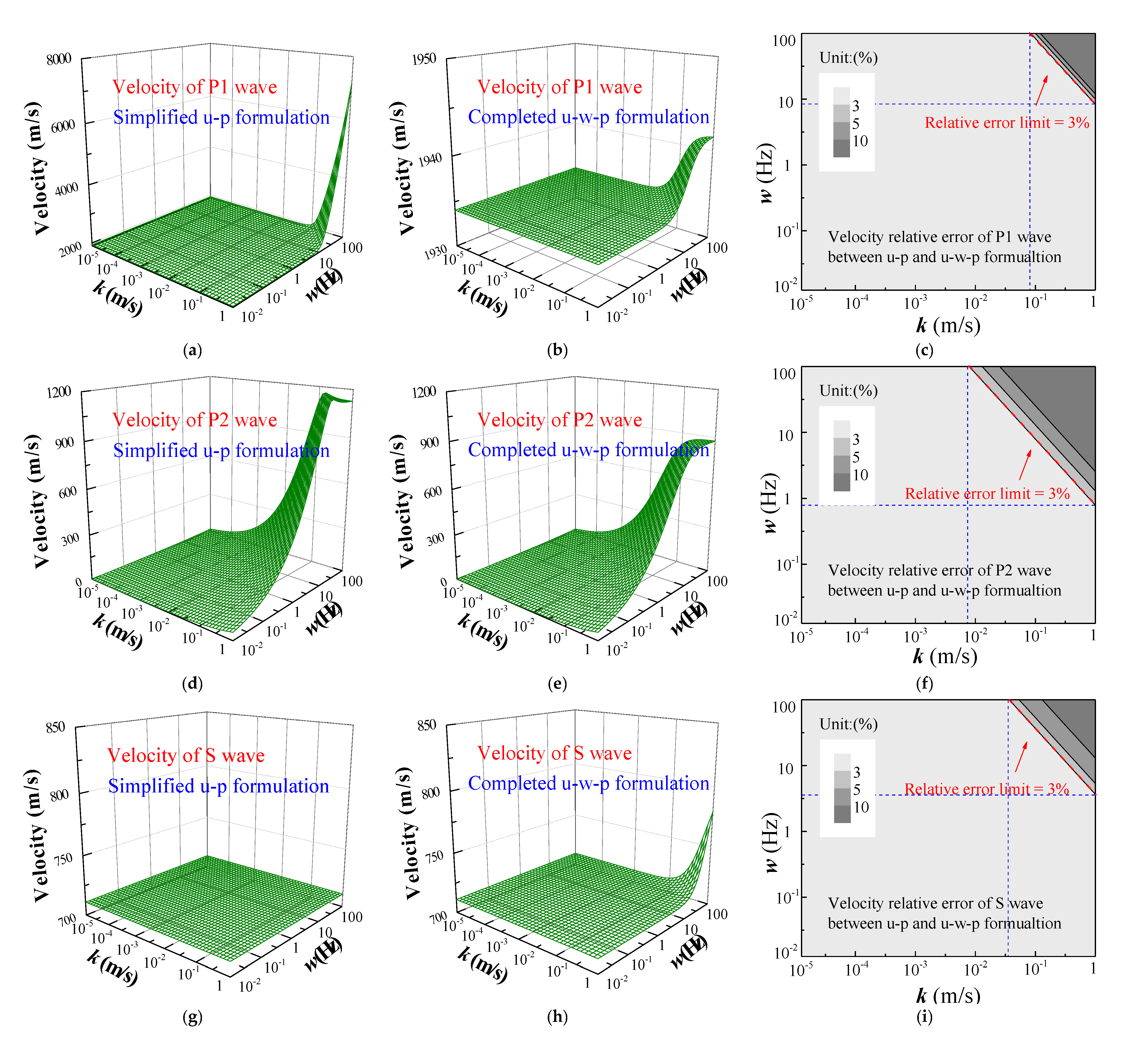
6. Analysis of the u-p Equation

Based on the u-p formulation, wave velocities and attenuated coefficients are deduced using the same procedure as the u-w-p formulation. Moreover, the scope of application of the u-p formulation is discussed.
Equation (7) is transformed into the frequency domain:
( λ + G ) u + G 2 u + ω 2 ρ u α p = 0
2 p + ω 2 ρ m Q b p + ω 2 α ρ m u = 0
where ρ m = 1 k ¯ i ω   . In the same way, using the Helmholtz decomposition, displacement u and pore pressure p, respectively, are substituted into Equations (53) and (54). We can obtain the equations expressed by potential functions:
( λ + 2 G + α 2 Q b ) 2 φ s + α Q b 2 φ f + ω 2 ρ φ s = 0
α Q b 2 φ s + Q b 2 φ f + ω 2 ρ m φ f = 0
G 2 ψ s + ω 2 ρ ψ s = 0
Equations (55)–(57) is written in a matrix form, shown as follows:
{ [ M ω 2 + K P 2 ] φ = 0 [ ρ ω 2 + G 2 ] ψ s = 0
where,
φ = [ φ s φ f ] ,   M = [ ρ ρ m ] ,   K P = [ λ + 2 G + α 2 Q b α Q b α Q b Q b ]
The characteristic equation of Equations (55)–(57) is:
| K P l P 2 M ω 2 | = 0
| G l S 2 ρ ω 2 | = 0
The solutions of Equation (59) are shown as follows:
( l P 1 , 2 ω ) 2 = ( 1 C P 1 , 2 ) 2 = ρ 1 , 2 λ + 2 G
( l S ω ) 2 = ( 1 C S ) 2 = ρ G
where,
ρ 1 , 2 = ρ ( b b 2 a c ) a = λ + 2 G Q b b = 1 2 ρ [ ρ m λ + 2 G + α 2 Q b Q b + ρ ] c = ρ m ρ
From Equation (62), we can see that the theoretical velocities of the P1 and P2 waves have the imaginary parts, but the shear wave has a constant velocity. Thus, the two compressional waves are attenuated and the shear wave is not attenuated during the propagation procedure.
In addition, Equation (60) is expanded as:
( λ + 2 G ) Q b ( l P ω ) 4 [ ( λ + 2 G + α 2 Q b ) ρ m + Q b ρ ] ( l P ω ) 2 + ρ ρ m = 0
The Equation (56) is substituted into Equation (55) and the following equation can be obtained
( λ + 2 G ) 2 φ s + ω 2 ρ φ s α ω 2 ρ m φ f = 0
Moreover, the eigenvectors corresponding to the eigenvalue in Equation (62) are expressed as follows:
{ a 1 T = ( 1 , η 1 ) a 2 T = ( 1 , η 2 )
where,
η 1 , 2 = α Q b Q b ρ m C P 1 , 2 2
Using Equation (67), the potential functions of the solid and fluid displacements can be expressed by the potential function of the P1 and P2 waves. The detailed relations are shown below:
{ φ s = φ P 1 + φ P 2 φ f = η 1 φ P 1 + η 2 φ P 2
The following two compressional wave equations can be obtained by substituting Equation (68) into Equation (66) and using Equation (65).
{ C P 1 2 2 φ P 1 = φ ¨ P 1 C P 2 2 2 φ P 2 = φ ¨ P 2
From Equation (69), the potential functions of displacements of P1 and P2 waves have the forms of wave equations. The wave equation of the S wave is the same as Equation (28). The velocities of the three waves refer to Equations (62) and (63).
To discuss the application of the u-p formulation, the product of k·ω of the permeability and the frequency is used as a variation. To explain the accuracy of the simplified u-p formulation, Figure 3 shows the differences in the velocities of P1, P2, and S waves, obtained from the simplified u-p formulation and the completed u-w-p formulation, respectively. In addition, comparisons of the velocities are conducted in saturated gravel soil, sand soil, clay silt and silt, respectively. In Figure 3, blue shade fields represent the actual range of k·ω. By discuss the relative errors of the velocities of the P1, P2 and S wave in the actual range, the scope of the application of the u-p formulation can be gotten preliminarily.
In clay silt and silt, value of k·ω is less than 10−3 and 10−6, respectively. In this scope, three velocities obtained from u-p formulation are same with them from the u-w-p formulation. The relative errors of the velocities between the two formulations are zeros. In gravel and sand soils, the values of k·ω are 10−5–102 and 10−7–1, respectively. In these scopes, both of the relative errors of the velocities between the two formulations are beyond the relative error limit of 3% in the two soils. Therefore, the application of the u-p formulation would be unsuitable in soils with high permeability, like sand and gravel. We mainly discuss the influence of the permeability and frequency on the wave velocities gained from the u-p formulation as the value of k·ω is between 10−7–102. In this range, the primary range of the loading frequency is 10−2–102 Hz, so the range of the permeability is 10−5 − 1 m/s.
Figure 4 shows the relations of the permeability, frequency, and the velocities in gravel. By comparing the relative errors of the velocities of P1, P2, and S waves, obtained from the u-p and u-w-p formulations, the variation of scope of the u-p formulation with increasing permeability and frequency are further discussed.
In Figure 4, the relative errors of the P2 wave velocities are the largest of the three waves. Therefore, taking the relative errors of the P2 wave velocities in sand soils as an example (in Figure 4), the relative errors of the three wave velocities obtained, respectively, from the u-p formulation and the u-w-p formulation are less than 3% as the permeability k is less than 10−2 m/s and frequency ω is less than 1 Hz. In addition, the permeability k and frequency ω satisfy the relation of ω = −100k + 101. Within this field, the wave velocities are mostly closed to the real velocities, and the u-p formulation can be safely used.

7. Conclusions

The propagation properties of waves in saturated soil are the theoretical basis for analyzing the dynamic problems of saturated soils. The waves and their propagation properties are also different in saturated soils with different permeabilities. In this paper, the following research works are carried out for saturated soils with different permeabilities, and the corresponding conclusions are obtained:
(1)
Based on the u-w-p formulation of saturated porous medium, the wave equations and the corresponding velocities of P1, P2, and S waves are acquired under zero, finite, and infinite permeabilities, respectively.
(2)
The differences in the permeability and loading frequency of saturated soils have different influences on propagation properties, such as the velocities, dispersion and attenuation characteristics.
(3)
For zero and infinite permeabilities, P1, P2, and S waves are not dispersed and attenuated in the propagation process. Wave velocities keep constants.
(4)
For the finite permeability, the solutions of wave equations have real and imaginary parts, which represent the wave shape and attenuation during the propagation process, respectively. The actual velocities are the real parts of the velocities.
(5)
In different saturated soils, the variation tendency of wave velocities and attenuation coefficients are similar, but the amplitudes of velocities and attenuation coefficients have obvious discrepancies. The harder the soil, the faster the wave velocity. The softer the soil, the faster the attenuation wave is.
(6)
As a simplified formulation, the application scope of the u-p formulation is further discussed. The u-p formulation can be safely used as permeability k is less than 10−2 m/s and frequency ω is less than 1Hz.
More simplified models, such as artificial boundaries, contact models, and algorithms, can be obtained based on the u-p formulation by selecting a suitable application scope in the future.

Author Contributions

Conceptualization, J.S.; data curation, J.S. and L.L.; funding acquisition, J.S. and C.X.; methodology, J.S. and L.L.; project administration, C.X.; software, J.S.; supervision, C.X.; validation, J.S. and L.L.; writing–original draft, J.S.; writing–review and editing, L.L. All authors have read and agreed to the published version of the manuscript.

Funding

This research was funded by National Natural Science Foundation of China, grant numbers 51808006 and 51722801, and the Natural Science Foundation of Beijing, China, grant number 8192012.

Acknowledgments

The authors would like to thank the National Natural Science Foundation of China (Grant No. 51808006 and No. 51722801) and the Natural Science Foundation of Beijing, China (Grant No. 8192012) for funding the work presented in this paper.

Conflicts of Interest

The authors declare no conflict of interest.

References

  1. Coussy, O.; Bourbie, T. Propagation des ondes acoustiques dans les milieux poreux saturés. Rev. De L institut Français Du Pétrole 1984, 39, 47–66. [Google Scholar] [CrossRef]
  2. Snieder, R.; Hubbard, S.; Haney, M.; Bawden, G.; Hatchell, P.; Revil, A. DOE Geophysical Monitoring Working Group. Advanced noninvasive geophysical monitoring techniques. Annu. Rev. Earth Planet. Sci. 2007, 35, 653. [Google Scholar] [CrossRef] [Green Version]
  3. Biot, M.A. Theory of propagation of elastic waves in a fluid-saturated porous solid. I. Low-frequency range. J. Acoust. Soc. Am. 1956, 28, 168–178. [Google Scholar] [CrossRef]
  4. Biot, M.A. Theory of propagation of elastic waves in a fluid-saturated porous solid. II. Higher frequency range. J. Acoust. Soc. Am. 1956, 28, 179–191. [Google Scholar] [CrossRef]
  5. Lévy, T. Propagation of waves in a fluid-saturated porous elastic solid. Int. J. Eng. Sci. 1979, 17, 1005–1014. [Google Scholar] [CrossRef]
  6. Auriault, J.L. Dynamic behaviour of a porous medium saturated by a Newtonian fluid. Int. J. Eng. Sci. 1980, 18, 775–785. [Google Scholar] [CrossRef]
  7. Prevost, J.H. Nonlinear transient phenomena in saturated porous media. Comput. Methods Appl. Mech. Eng. 1982, 30, 3–18. [Google Scholar] [CrossRef]
  8. Zienkiewicz, O.C.; Shiomi, T. Dynamic behaviour of saturated porous media; the generalized Biot formulation and its numerical solution. Int. J. Numer. Anal. Methods Geomech. 1984, 8, 71–96. [Google Scholar] [CrossRef]
  9. Zienkiewicz, O.C.; Chang, C.T.; Bettess, P. Drained, undrained, consolidating and dynamic behaviour assumptions in soils. Geotechnique 1980, 30, 385–395. [Google Scholar] [CrossRef]
  10. Zienkiewicz, O.C. Basic formulation of static and dynamic behaviours of soil and other porous media. Appl. Math. Mech. 1982, 3, 457–468. [Google Scholar] [CrossRef]
  11. Gajo, A.; Mongiovi, L. An analytical solution for the transient response of saturated linear elastic porous media. Int. J. Numer. Anal. Methods Geomech. 1995, 19, 399–413. [Google Scholar] [CrossRef]
  12. Gajo, A. Influence of viscous coupling in propagation of elastic waves in saturated soil. J. Geotech. Eng. 1995, 121, 636–644. [Google Scholar] [CrossRef]
  13. Plona, T.J. Observation of a second bulk compressional wave in a porous medium at ultrasonic frequencies. Appl. Phys. Lett. 1980, 36, 259–261. [Google Scholar] [CrossRef] [Green Version]
  14. Rasolofosaon, P.N.J. Importance of interface hydraulic condition on the generation of second bulk compressional wave in porous media. Appl. Phys. Lett. 1988, 52, 780–782. [Google Scholar] [CrossRef]
  15. Nagy, P.B.; Adler, L.; Bonner, B.P. Slow wave propagation in air-filled porous materials and natural rocks. Appl. Phys. Lett. 1990, 56, 2504–2506. [Google Scholar] [CrossRef]
  16. Berryman, J.G. Confirmation of Biot’s theory. Appl. Phys. Lett. 1980, 37, 382–384. [Google Scholar] [CrossRef]
  17. Kafaji, I.K.A. Formulation of a Dynamic Material Point Method (MPM) for Geomechanical Problems. Ph.D. Thesis, University of Stuttgart, Institut for Geotechnical Engineering, Stuttgart, Germany, 2013. [Google Scholar]
  18. Corapcioglu, M.Y.; Tuncay, K. Propagation of waves in porous media. Adv. Porous Media 1996, 3, 361–440. [Google Scholar]
  19. Berryman, J.G. Seismic wave attenuation in fluid-saturated porous media. Scatt. Attenuations Seism. Waves 1988, 128, 423–432. [Google Scholar]
  20. Schmitt, D.P. Acoustic multipole logging in transversely isotropic poroelastic formations. J. Acoust. Soc. Am. 1989, 86, 2397–2421. [Google Scholar] [CrossRef]
  21. Sharma, M.D.; Gogna, M.L. Wave propagation in anisotropic liquid-saturated porous solids. J. Acoust. Soc. Am. 1991, 90, 1068–1073. [Google Scholar] [CrossRef]
  22. Zhou, F.X.; Lai, Y.M. Propagation characteristics of elastic wave in saturated frozen soil. Rock Soil Mech. 2011, 32, 2669–2674. [Google Scholar]
  23. De Boer, I.R.; Liu, Z. One-dimensional transient wave propagation in fluid-saturated incompressible porous media. Arch. Appl. Mech. 1993, 63, 59–72. [Google Scholar] [CrossRef]
  24. Liu, Z.; de Boer, R. Dispersion and attenuation of surface waves in a fluid-saturated porous medium. Transp. Porous Media 1997, 29, 207–223. [Google Scholar] [CrossRef]
  25. Kumar, R.; Hundal, B.S. Symmetric wave propagation in a fluid-saturated incompressible porous medium. J. Sound Vib. 2005, 288, 361–373. [Google Scholar] [CrossRef]
  26. Kumar, R.; Hundal, B.S. Surface wave propagation in a fluid-saturated incompressible porous medium. Sadhana 2007, 32, 155–166. [Google Scholar] [CrossRef] [Green Version]
  27. Dutta, N.C. Theoretical analysis of observed second bulk compressional wave in a fluid-saturated porous solid at ultrasonic frequencies. Appl. Phys. Lett. 1980, 37, 898–900. [Google Scholar] [CrossRef]
  28. Li, P.; Song, E.X. Compressional wave velocity and its physical nature in saturated soils with extreme permeability values. Rock Soil Mech. 2012, 33, 1979–1985. [Google Scholar]
  29. Kim, S.H.; Kim, K.J.; Blouin, S.E. Analysis of wave propagation in saturated porous media. I. Theoretical solution. Comput. Methods Appl. Mech. Eng. 2002, 191, 4061–4073. [Google Scholar] [CrossRef]
  30. Kim, S.H.; Kim, K.J.; Blouin, S.E. Analysis of wave propagation in saturated porous media. II. Parametric studies. Comput. Methods Appl. Mech. Eng. 2002, 191, 4075–4091. [Google Scholar] [CrossRef]
  31. Yang, J.; Wu, S.M.; Cai, Y.Q. Characteristics of propagation of elastic waves in saturated soil. J. Vib. Eng. 1996, 9, 128–137. [Google Scholar]
  32. Steeb, H.; Kurzeja, P.S.; Frehner, M.; Schmalholz, S.M. Phase velocity dispersion and attenuation of seismic waves due to trapped fluids in residual saturated porous media. Vadose Zone J. 2012, 11. [Google Scholar] [CrossRef] [Green Version]
  33. Han, B.; Zdravkovic, L.; Kontoe, S. Numerical and analytical investigation of compressional wave propagation in saturated soils. Comput. Geotech. 2016, 75, 93–102. [Google Scholar] [CrossRef] [Green Version]
  34. Zheng, P.; Ding, B.; Zhao, S.-X.; Ding, D. Dynamic response of a multilayered poroelastic half-space to harmonic surface tractions. Transp. Porous Media 2013, 99, 229–249. [Google Scholar] [CrossRef]
  35. Liu, G.L.; Song, E.X. Visco-elastic transmitting boundary for numerical analysis of infinite saturated soil foundation. Chin. J. Geotech. Eng. 2006, 28, 2128–2133. [Google Scholar]
  36. Liao, Z.P. Introduction to Wave Motion Theories in Engineering; Science Press: Beijing, China, 2002. [Google Scholar]
  37. Deeks, A.J.; Randolph, M.F. Axisymmetric time-domain transmitting boundaries. J. Eng. Mech. 1994, 120, 25. [Google Scholar] [CrossRef]
Figure 1. Relations of permeability, frequency and the velocities of three waves in four saturated soils.
Applsci 11 08138 g001
Figure 2. Relations of permeability, frequency and attenuation coefficients of three waves in four saturated soils.
Applsci 11 08138 g002
Figure 3. Comparisons of the velocities obtained from u-p and u-w-p formulation in the four saturated soils.
Applsci 11 08138 g003aApplsci 11 08138 g003b
Figure 4. Velocities obtained from u-p and u-w-p formulations and relative errors of velocities in saturated gravel soil.
Applsci 11 08138 g004
Table 1. Definitions of symbols.
SymbolsDefinitions
uDisplacement of soil skeleton
wDisplacement of pore fluid with respect to the soil skeleton
pPore pressure
ρ Density of the solid–fluid mixture
ρ f Density of the fluid
nPorosity
bBody force acceleration
kPermeability coefficient of pore fluid k ¯ = k / ρ f g
k ¯ Dynamic permeability coefficient
σ Total stress of the two-phase mediaConstitutive relationship: σ = σ α m p ;
m T = [ 1 1 0 ] ; T = [ x y ]
σ Effective stress of the soil skeleton
α Compressibility coefficient of solidKT = E/[3(1 − 2v)] = λ + 2G/3; where, KT, KS and Kf are the bulk modulus of soil skeleton, soil particles and pore fluid respectively.
For the material of soil, soil particles are nearly incompressible relative to the soil skeleton, thus they have the relations of KS >> KD, α ≈ 1.
QbCompressibility coefficient of fluid
Table 2. Material parameters of four saturated soils.
ParameterSaturated Gravel SoilSaturated Sand SoilSaturated Clay SiltSaturated Silt
Elastic modulus E (MPa)2000700166.864.7
Shear modulus G (MPa)854.7277.864.1521.7
Density of fluid ρ f (kg/m3)1000100010001000
Density of soil ρ s (kg/m3)2150210019701700
Poisson ratio υ 0.170.260.30.49
Bulk modulus of fluid Kf (GPa)1.851.851.851.85
Bulk modulus of solid KS (GPa)45302012
Porosity n0.40.40.5940.625
Permeability k (m/s)3.24 × 10−3
or 1 × 10⁻¹² − 1
4.6 × 10⁻⁴
or 1 × 10⁻¹² − 1
5.79 × 10⁻⁶
or 1 × 10⁻¹² − 1
6 × 10⁻¹⁰
or 1 × 10⁻¹² − 1
Frequency f = ω / 2 π (/s)0–2000–2000–2000–200
Publisher’s Note: MDPI stays neutral with regard to jurisdictional claims in published maps and institutional affiliations.

