Article

Enhanced Heat Transfer Performance of the Tube Heat Exchangers Using Carbon-Based Nanofluids

1
College of Mechanical & Electrical Engineering, National Taipei University of Technology, No. 1, Sec. 3, Zhongxiao E. Rd., Taipei 10608, Taiwan
2
Undergraduate Program of Vehicle and Energy Engineering, National Taiwan Normal University, No. 162, Sec. 1, He-ping E. Road, Da-an District, Taipei 10610, Taiwan
3
Department of Industrial Education, National Taiwan Normal University, No. 162, Sec. 1, He-Ping E. Road, Da-an District, Taipei 10610, Taiwan
*
Author to whom correspondence should be addressed.
Appl. Sci. 2021, 11(17), 8139; https://doi.org/10.3390/app11178139
Submission received: 30 July 2021 / Revised: 25 August 2021 / Accepted: 31 August 2021 / Published: 2 September 2021

Abstract

:
The wet ball milling method was used and a dispersant (gum Arabic) was added to prepare various concentrations (0.05 and 0.2 wt%) of carbon-based nanofluids (CBNFs) by a two-step synthesis method as working fluids for heat exchange. CBNFs were actually used in a tube heat exchanger (THE) for heat transfer performance experiments. The heat transfer performance of water and CBNFs was estimated under different heating powers and flow rates of working fluid. The pump power consumption (Ppe) of 0.05 wt% CBNF was found to be similar to that of water, but the Ppe of 0.2 wt% CBNF was higher than that of water. The convective heat transfer coefficient (HTC) of CBNF in the was higher than that of water, and the HTC of 0.05 wt% and 0.2 wt% CBNF was optimal at the heating power of 120 W and 80 W, respectively. The average HTC of 0.05 wt% CBNFs at 120 W heating power was about 3.33% higher than that of water, while that of 0.2 wt% CBNFs at 80 W heating power was about 4.52% higher than that of water. Considering the Ppe and HTC concomitantly, the best overall system performance was exhibited by 0.05 wt% CBNFs.

1. Introduction

Research on nanofluids in heat exchange, energy storage, and thermal collection systems has been very vigorous in recent years, and most studies show that nanofluids (NFs) can effectively improve system efficiency and operating performance in these systems [1,2,3,4,5]. In particular, the carbon-based nanofluids (CBNFs) prepared by adding carbon-based nanomaterials (CBNMs) have attracted more attention from researchers. CBNMs mainly include single-walled nanotubes (SWCNTs), double-walled carbon nanotubes (DWCNTs), multi-walled carbon nanotubes (MWCNTs), graphene (GN), graphene nanoplatelets (GNP), graphene oxide (GO), and reduced graphene oxide. Most of these materials have excellent stability and thermal properties. In particular, CNTs and graphene have received great attention because of their large aspect ratio, and special optical, mechanical, physical, and chemical properties. Therefore, CBNFs have been commonly used in heat exchange, thermal storage, and thermal collection systems to improve system performance [6,7,8,9,10]. In addition, high-performance CBNFs should have considerable potential in the application of relevant cutting-edge technologies in the future [11].
Many researchers have applied CBNFs to air-cooled heat exchangers (ACHEs) or radiators [12,13,14,15], shell and tube heat exchangers [16,17,18], plate heat exchangers (PHE) [19,20,21,22,23], and double tube or tube heat exchangers [24,25,26] to improve heat exchange performance. In addition, different base fluids (BFs) such as water (W), ethylene glycol aqueous solution (EG-W) and lubricating oil are configured CBNFs for adapting to different use objects and temperature ranges. The application of CBNFs in heat exchangers can improve the convective heat transfer coefficient (HTC) or heat exchange capacity of the heat exchanger (HE), while also slightly increasing the power consumption of the pump that transports the fluid. However, very few studies have shown that CBNFs do not help the performance of heat exchangers [14,27]. The results of the experimental research on the use of CBNFs in different HEs in recent years are summarized in Table 1. Table 1 includes adding materials, BFs, concentration, HE types, and main findings.
According to these research results, CBNFs can improve the HTC or heat exchange capacity of HEs, mainly because CBNFs have higher thermal conductivity (k), strong Brownian motion, collision behavior between CBNMs and CBNMs with the wall of the HE, and a high energy delivery rate of CBNMs [12,13,15,21]. However, the use of CBNFs as the working fluid of the HE increases the ΔP of the HE mainly because of the higher viscosity (μ) of CBNFs [13,15,22,23,24,25,26]. High-concentration CBNFs do not necessarily have better heat transfer performance than low-concentration CBNFs [15,22]. In this study, a high-pressure combustion method (HPCM) was used to prepare CBNMs, and the CBNMs was prepared for various concentrations (0.05 and 0.2 wt%) of CBNFs by a two-step synthesis method as working fluids for heat exchange. The CBNFs were actually used in a tube heat exchanger (THE) for heat transfer performance experiments. An electric heater was used as a heat source to actually evaluate the performance of the THE in terms of the HTC, flow loss, heater temperature, pump power consumption, and so on in various working fluids, heating powers, and flow rates. Then the results of the performance test were adopted to assess the practicability of CBNFs as working fluid in the THE.

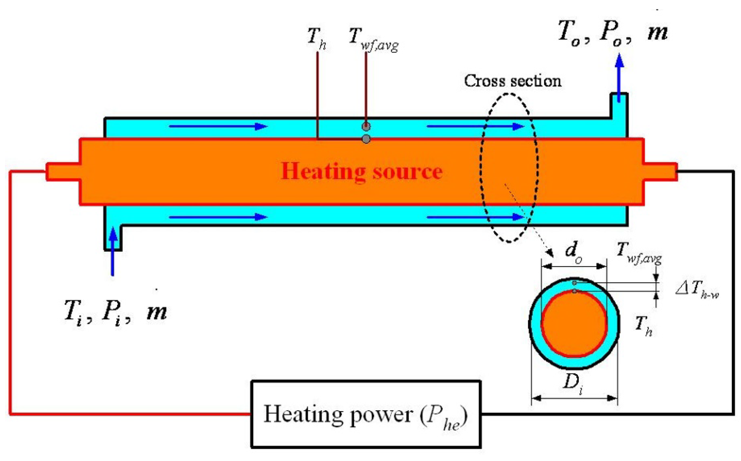
2. Performance Calculations of the Tube Heat Exchanger

The schematic cross-section of a THE is shown in Figure 1. The inner tube is the heat source, and the outer tube is for circulating working fluid. A THE can be used in hot water heaters or for heat dissipation of specific heat sources. The HTC (W/m2 °C) of the working fluid in the outer tube can be expressed as [28,29]:
H T C = P h e A ( T h T w f , a v g ) = P h e A × Δ T h w
T w f , a v g = T i + T o 2
where Phe is the heating power of the heat source (W), A is the average surface area between the inner tube and the outer tube (m2), Th is the average surface temperature of the heat source (°C), Twf, avg is the average temperature of the working fluid (°C).
The flow loss (Pf, W) of the working fluid flowing through the THE is the product of the (G, m3/s) of the working fluid and the ΔP (Pa) of THE:
P f = G × ( P i P o ) = G × ( Δ P )
From the cross-section of the THE in Figure 1, Re can be calculated using Equations (4)–(7) [20,30,31]:
Re = ρ G D h μ A c
D h = 4 A c W P
A c = π 4 ( D i 2 d o 2 )
W P = π ( D i + d o )
where Dh is the hydraulic diameter (m), ρ is the density of the working fluid (kg/m3), μ is the viscosity of the working fluid (Pa-s), Ac is the cross-sectional area of the working fluid flowing through the tube (m2), WP is the wet perimeter (m), do is the outer diameter of the internal tube (m), and Di is the inner diameter of the outer tube (m).

3. Experiment

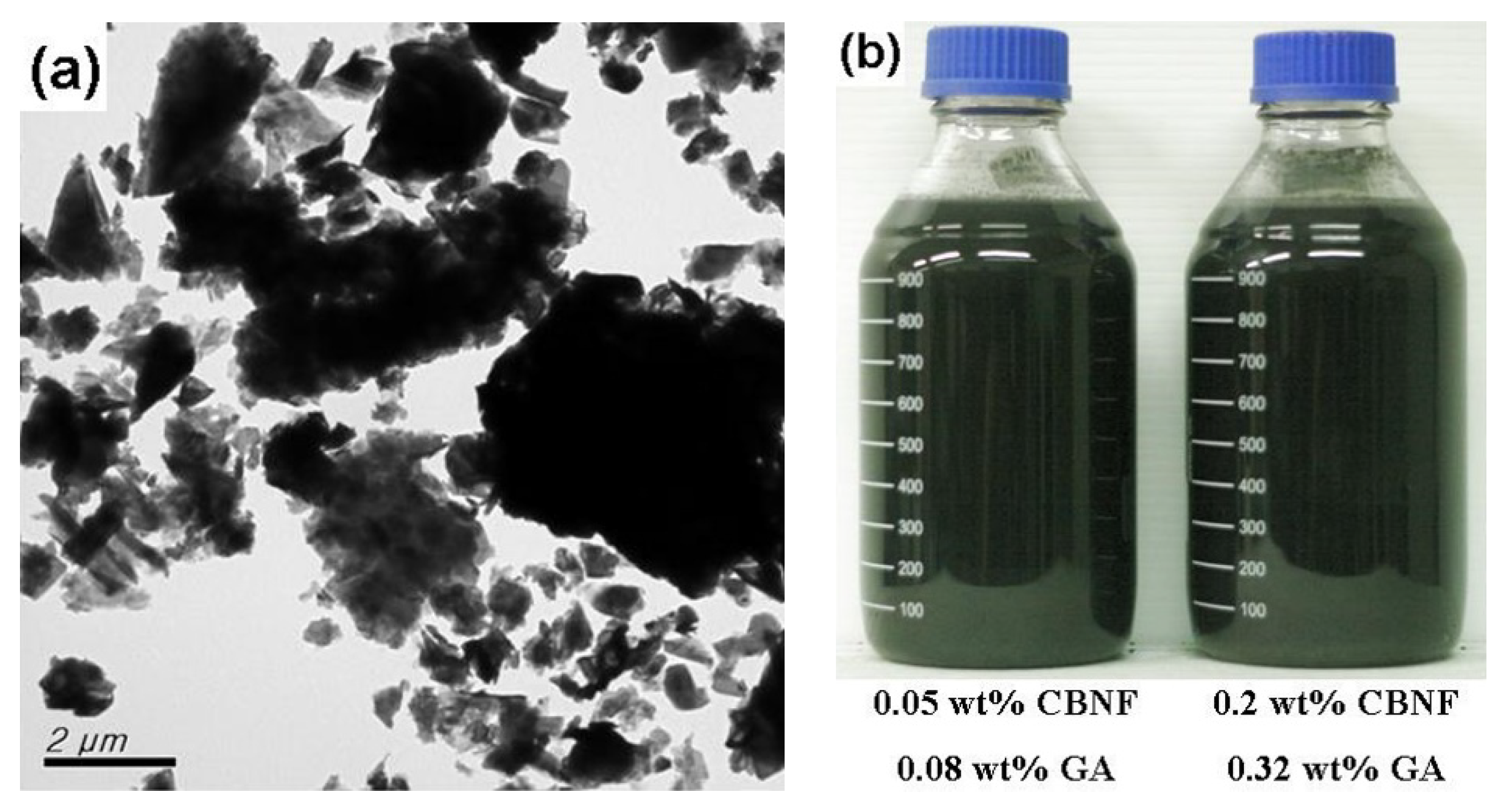
3.1. Preparation of CBNFs

The CBNMs used in the CBNFs were produced using a HPCM with graphite powder (average particle size = 3.2 μm) at an oxygen pressure of 1.5 MPa. HPCM was described in detail in a previous study [32]. The main compositions of the CBNMs were hexagonal graphite-2H, amorphous carbon, and a tiny amount of defective diamond that was confirmed by X-ray diffraction (XRD; D8 Advanced, Bruker, Rheinstetten, Germany) [32]. Due to the serious agglomeration of the CBNMs produced by HPCM, the CBNMs were ground and dispersed using a high-speed ball mill (MM400, Retsch, Haan, Germany). To further break the agglomerated CBNMs and form the CBNFs, wet milling (weight ratio of CBNMs to water was 1:12) was executed for 120 min (procedure: (1/10 s)/30 min → (1/20 s)/20 min → (1/30 s)/20 min → (1/20 s)/20 min → (1/10 s)/30 min). This method of fabricating CBNFs is a two-stage synthesis method. Figure 2a shows the image of CBNMs under a transmission electron microscope (TEM; H-7100, Hitachi, Saitama, Japan). Here, the CBNMs were observed to be flaky and multilayered. Most of the plane dimensions were about several hundred nanometers; however, the thickness should be below 100 nm. Water was added to the ball-milled CBNFs to dilute it to CBNFs with CBNMs’ concentration of 1.0 wt%. CBNF (1.0 wt%) was added with 1.6 wt% gum Arabic (GA; First Chemical, Taiwan) as a dispersant to preserve the long-term stability of CBNFs. The optimal GA concentration was 1.6 wt%, determined by observing the sedimentation state after standing for 24 days. Then, 1.0 wt% CBNF with 1.6 wt% GA was alternately dispersed using an electromagnetic stirrer (PC420D, Corning, Corning, NY, USA), an ultrasonic bath (5510R-DTH, Branson, St. Louis, MO, USA), a homogenizer (YOM300D, Yotec, Taiwan), and an ultrasonic liquid processor (Q700, Qsonica, Newton, CT, USA). The aforementioned dispersion method was repeated three times to keep superior stability for the CBNFs based on our past research experience [30,33,34,35]. Next, 1.0 wt% CBNF with 1.6 wt% GA was further diluted with water to a final concentration of 0.05 wt% and 0.2 wt% CBNFs, and the ratio of GA to CBNMs in each CBNFs was fixed at 8:5. Then, 0.05 wt% and 0.2 wt% CBNFs were processed following the above dispersion procedure and were used as the experimental sample for this study. Figure 2b shows actual image of CBNFs that had been placed for more than one month. The CBNFs at the two concentrations are dark black, and the difference in concentration cannot be distinguished by the naked eye; moreover, it will not cause obvious sedimentation after being placed for more than one month.

3.2. Density and Viscosity Measurement

The ρ and μ were measured using a density meter (DA-645, KEM, Kyoto, Japan; density and temperature accuracies of ±0.0005 g/cm3 and ±0.03 °C, respectively) and viscometer (VL700-T15, Hydramotion, Malton, UK; accuracy: ±1.0%) at various sample temperatures, respectively. The ρ and μ of each sample and its temperature was measured five times and then averaged as the final experimental value of the sample to minimize deviations in measurement. Table 2 lists the μ and ρ of working fluids. The μ and ρ of all samples are inversely proportional to the temperature of the sample. The ρ of CBNFs should be higher than water to meet the theory of solid-liquid mixtures because CBNMs have a higher ρ than water. However, because of the very low concentration of CBNMs, the ρ characteristics of GA aqueous solution at high temperature, and the measurement of the deviation of the density 0.05% CBNF at 50 °C and 60 °C was slightly lower than that of water (the difference between the ρ of water and 0.05 wt% CBNF was within 0.08%). In addition, the μ of the solid-liquid mixture is usually higher than that of the base fluid, so the μ of CBNFs is proportional to the added concentration of CBNMs. Furthermore, the μ of CBNFs has an inverse relationship with sample temperature [36]. The temperature of μ and ρ of the working fluid is the arithmetic mean temperatures of inlet and outlet temperatures (Ti and To) on the working fluid side of the THE when calculating Re. At this arithmetic mean temperature, μ and ρ were obtained using the polynomial regression method in conjunction with the values listed in Table 2.

3.3. Heat Transfer Performance Experiments

Figure 3 displays the experimental diagram of THE heat transfer performance. A threaded electric heater was placed in the stainless-steel circular tube (OD: 31.5 mm), and the internal gap between the heater and the stainless-steel circular tube was filled with iron powder. Then, a T-type thermocouple (L = 45 cm, ø = 2 mm; Jetec, Taiwan; accuracy: ±0.75%) with a stainless-steel protective tube was installed on the inner wall of the stainless-steel circular tube to measure the temperature of the heating tube (Th), and the two ends were sealed with heat-resistant epoxy resin to form an inner tube with heating function. Finally, the inner tube was placed in a PVC circular tube (ID: 35 mm) with an inlet and outlet at both ends and sealed with heat-resistant epoxy resin to form a THE.
The inner tube used a programmable power supply (DC 5-300V/0.01-3A/300 W; MP-3AP, Major Science, Taiwan; accuracy: ±1.0 W) to provide 80 W and 120 W heating sources in a constant power mode. T-type thermocouples (0.3 mm × 2 C; Jetec, Taiwan; accuracy: ±0.75%) and pressure transducers (0–1.0 bar; JPT 131S-LJ, Jetec, Taiwan; accuracy: ±0.25%) were mounted at the inlet and outlet of the working fluid side of the to measure temperature and pressure. The inlet temperature of the working fluid was controlled at 30 °C using a temperature controller (TTM-i4N, TOHO, Kanagawa, Japan; accuracy: ±0.3%). The flow rate of the working fluid was controlled at the target value (1.5, 2.5, 3.5, 4.5, and 5.5 LPM) using a flow control valve (0-10 LPM; FCV-10, Regal Joint, Kanagawa, Japan; accuracy: ±3.0%). A plate heat exchanger (K025-10F-P4, Kaori, Taiwan) with an isothermal unit (20 L, −20–100 °C; RC20, Yotec, Taiwan; accuracy: ±0.5 °C) was used to cool the temperature of the working fluid entering the heating water tank to below 30 °C in order that the electric heater in heating water tank can stably control the inlet temperature of the at 30 °C. The temperature and humidity of the experimental environment were controlled at 25 ± 1.0 °C and 65 ± 5% RH, respectively, by the temperature/humidity control system. The external side of the plate heat exchanger, heating water tank, THE, and connecting pipes was covered with PU foam insulation material (pipeline insulation thickness, 1.25 cm; equipment insulation thickness, 2.5 cm) to maintain experimental stability. All temperature, pressure, and flow data were measured and recorded using a data logger (TRM-20, TOHO, Kanagawa, Japan; accuracy: ±0.1%) with an interval time of 5 s. The power consumption of the water pump (1/8 HP, maximum: 68 LPM; 5MD-HC, Little Giant, Wayne, Indiana, USA) was measured and recorded using a power meter (KEW 6305, Kyoritsu, Tokyo, Japan; power accuracy: ±1.0%) with an interval time of 5 s. The time for each experimental parameter was 20 min, and stable data acquired over the last 10 min were recorded, averaged, and used as the experimental data. The same experimental parameters were repeated five times, and the average of five readings was the final experimental result. The relevant experimental results were used to calculate the relevant performance indicators of the system through Equations (1)–(7).

3.4. Data Analysis and Relative Uncertainty

The percentage differences (R) between the experimental data of water (DTw) and those of CBNFs (DTCBNFs) can be expressed as Equation (8):
R = [ ( D T C B N F s D T w ) / D T w ] × 100 %
The relative uncertainty analysis performed herein involved the calculation of measurement deviations (ε) of the instrument. According to Equation (9) for standard uncertainty analysis [30,31], the range of relative uncertainty of μ and ρ were within ±1.95 and ±0.12%, respectively. The relative uncertainty ranges of Re, HTC, Pf, and ΔTh-w were ±3.59%, ±1.83%, ±3.04%, and ±1.34%, respectively. The same experimental parameters were repeated five times; hence, the relative uncertainty of the final experimental data was further reduced. The relative uncertainty ranges in the heat transfer experiments did not include any deviations caused by using the polynomial regression method to calculate the μ, ρ, and cp of the samples along with the measured temperature, dimensional deviations in THE machining, and ambient conditions.
u ε = ( ε 1 ) 2 + ( ε 2 ) 2 + + ( ε n ) 2 × 100 %

4. Results and Discussion

The Re of the test sample for THE at various experimental parameters is shown in Figure 4. The Re is in laminar flow under most of the experimental parameters (only two experimental parameters with water at 5.5 LPM had Re slightly higher than 2100). An increase in the ρ of the working fluid increases the Re, while an increase in the μ of the working fluid decreases the Re at the same flow rate. The difference in ρ of water and CBNFs is very small (within 0.13%), so, the difference in Re that affects water and CBNFs is mainly due to the difference in μ of water and CBNFs. CBNFs have a significantly higher μ than that of water. Therefore, the Re of CBNFs is expected to be lower than that of water at the same flow rate and heating power. In terms of the average value of the overall flow range, the Re of 0.05 wt% CBNF and 0.2 wt% CBNF at a heating power of 80 W was 9.20% and 11.12% lower than that of water, respectively. Likewise, the Re of 0.05 wt% CBNF and 0.2 wt% CBNF at a heating power of 120 W was 9.73% and 11.74% lower than that of water, respectively.
The Pf of test sample for THE at various experimental parameters is presented in Figure 5, according to which, the CBNFs flowing through THE have a greater Pf than water under the same flow rate and heating power. This phenomenon is mainly due to the higher μ of CBNFs, which results in a higher pressure drop when flowing through THE. In addition, in the case of 5.5 LPM, the difference between the Pf of CBNFs and water increases significantly. This phenomenon occurs mainly because, at high flow rates, the two-phase flow characteristics of CBNFs are more obvious, which leads to an increase in pressure drop of the. In terms of the average value of the overall flow range, the Pf of 0.05 wt% CBNF and 0.2 wt% CBNF at a heating power of 80 W is 6.46% and 7.00% higher than that of water, respectively; likewise, the Pf of 0.05 wt% CBNF and 0.2 wt% CBNF at a heating power of 120 W is 6.70% and 6.75% higher than that of water, respectively.
The pump power consumption (Ppe) of the test sample for THE system at various experimental parameters is presented in Figure 6. According to this figure, the use of CBNFs as a working fluid in THE system has little effect on Ppe compared with that of water under the same flow rate and heating power. Some 0.05 wt% CBNFs have a slightly lower Ppe than water when the heating power is 120 W. This phenomenon is mainly because CBNMs and GA in CBNFs provide a lubrication effect on the rotating machinery of the pump and reduce the effect of viscosity on the Ppe. In addition, the flow resistance of the working fluid in the pipeline does not have a significant influence on the centrifugal pump. Therefore, we observed no fixed relationship between the Ppe in the system and the Pf of the working fluid in the for CBNFs and water. In terms of the average value of the overall flow range, the Ppe of 0.05 wt% and 0.2 wt% CBNF at a heating power of 80 W was 0.64% and 2.86% higher than that of water, respectively; likewise, the Ppe of 0.05 wt% and 0.2 wt% CBNF at a heating power of 120 W had a difference of −0.65% and 1.48%, respectively, compared to that of water.
Figure 7 shows the Th of test sample for THE at various experimental parameters. According to the figure, the use of CBNFs can reduce the Th under the same flow rate and heating power, and in most cases, 0.2 wt% CBNF can reduce the Th better than 0.05 wt% CBNF. A low heater temperature helps to extend the service life of the heater. Generally, a high-concentration NF has a higher k and can provide better heat conduction. However, most of the total heat transfer capacity of the working fluid in the HE with forced circulation comes from convective heat transfer. The primary factors affecting the convective heat transfer performance are the flow rate of the working fluid and the contact state between the working fluid and the tube wall. The variation in the k of the working fluid has little effect on the total heat transfer capacity so that two CBNFs with a four-fold difference in concentration have no significant difference in reducing the Th. Therefore, the factor that CBNFs can reduce is mainly that the Th should be a better combination between the tube wall and the working fluid. Furthermore, CBNFs can achieve a higher mass flow rate because of their higher ρ under the same volumetric flow rate and heating power. Therefore, a higher mass flow rate of the working fluid can also provide a larger convective heat transfer capacity and thus reduce the Th. In terms of the average value of the overall flow range, the Th of 0.05 wt% and 0.2 wt% CBNF at a heating power of 80 W was found to be 0.09 °C and 0.39 °C lower than that of water, respectively, while the Th of 0.05 wt% and 0.2 wt% CBNF at a heating power of 120 W was 0.28 °C and 0.23 °C lower than that of water, respectively.
The ΔTh-w (temperature difference between heater and working fluid) of test sample for THE at various experimental parameters is presented in Figure 8, according to which, the ΔTh-w of CBNFs is smaller than that of water under the same flow rate and heating power, indicating that using CBNF as the working fluid in THE can obtain a higher HTC (refer to Equation (1)). In terms of the average value of the overall flow range, the ΔTh-w of 0.05 wt% and 0.2 wt% CBNF at a heating power of 80 W is 1.97% and 3.70% lower than that of water, respectively, while theΔTh-w of 0.05 wt% and 0.2 wt% CBNF at a heating power of 120 W is 2.77% and 2.34% lower than that of water, respectively.
The HTC of the test sample for THE at various experimental parameters is shown in Figure 9. The figure shows that the HTC of CBNFs in most cases (except 0.05 wt% CBNF at 4.5 LPM and 80 W) was higher than that of water under the same flow rate and heating power, indicating that using CBNF as the working fluid in THE can lead to a higher convective heat transfer performance. In terms of the average value of the overall flow range, the HTC of 0.05 wt% and 0.2 wt% CBNF at a heating power of 80 W was 2.40% and 4.52% higher than that of water, respectively, while the HTC of 0.05 wt% and 0.2 wt% CBNF at a heating power of 120 W was 3.33% and 2.96% higher than that of water, respectively. While CBNFs as the working fluid can lead to a high convective heat transfer performance, its use in the system also leads to higher Ppe. To further compare the efficiency of the THE system using different working fluids, this study defined the performance index (PIe) as the ratio of the HTC to the Ppe as shown in Equation (10).
P I e = H T C P p e
The PIe of the test sample for the THE system at various experimental parameters is shown in Figure 10. In terms of the overall average value, the PIe of 0.05 wt% and 0.2 wt% CBNF at a heating power of 80 W was 1.72% and 1.54% higher than that of water, respectively, while the PIe of 0.05 wt% and 0.2 wt% CBNF at a heating power of 120 W was 4.04% and 1.42% higher than that of water, respectively. These PIe values show that the system efficiency of 0.05 wt% CBNF was better than that of 0.2 wt% CBNF and is more suitable for the THE system.

5. Conclusions

In this study, the HPCM was used to prepare CBNM, which was then used to prepare CBNFs by a two-step synthesis method. Water and CBNFs were used in THE for the heat exchange performance experiments at varying flow rates and heating powers of the working fluid. The specific research results are summarized as follows.
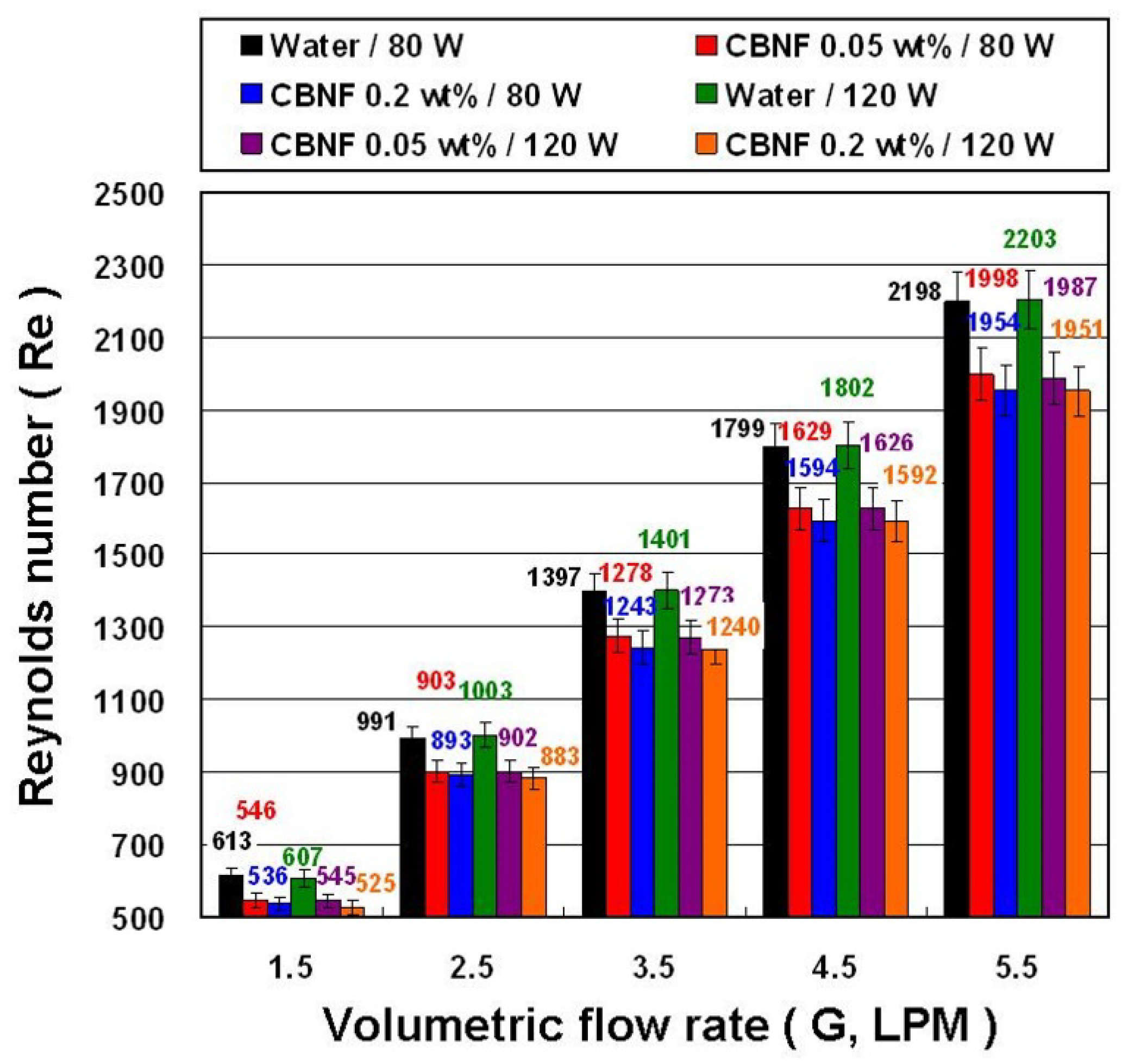
  • The CBNFs have a lower Re than that of water because CBNFs have higher μ.
  • The CBNFs flowing through the THE have a greater Pf than that of water under the same experimental parameters. This phenomenon is mainly because CBNFs have a higher μ, which results in a higher pressure drop when flowing through the THE.
  • CBNFs as a working fluid in a THE system have little effect on Ppe compared with water under the same experimental parameters.
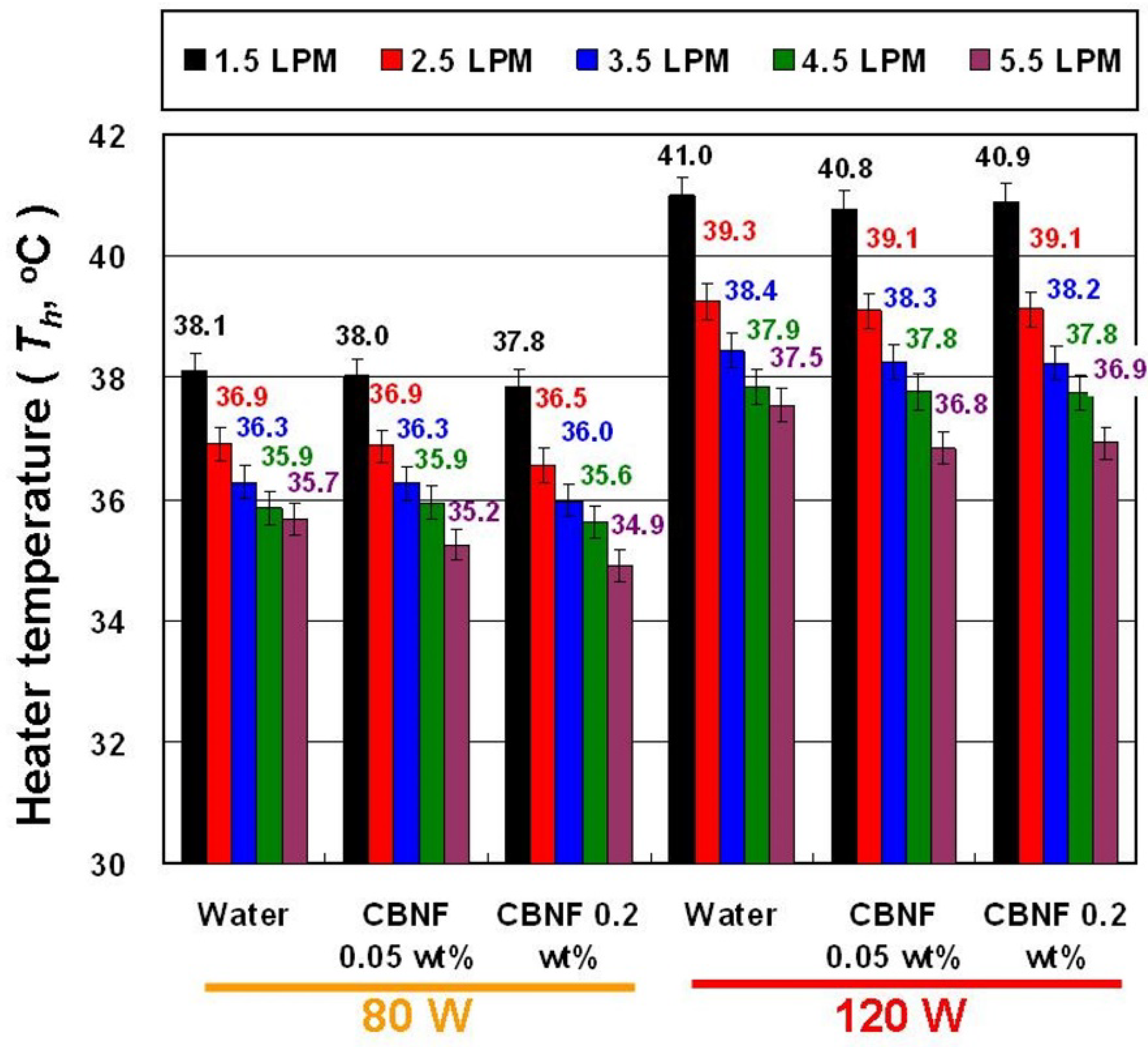
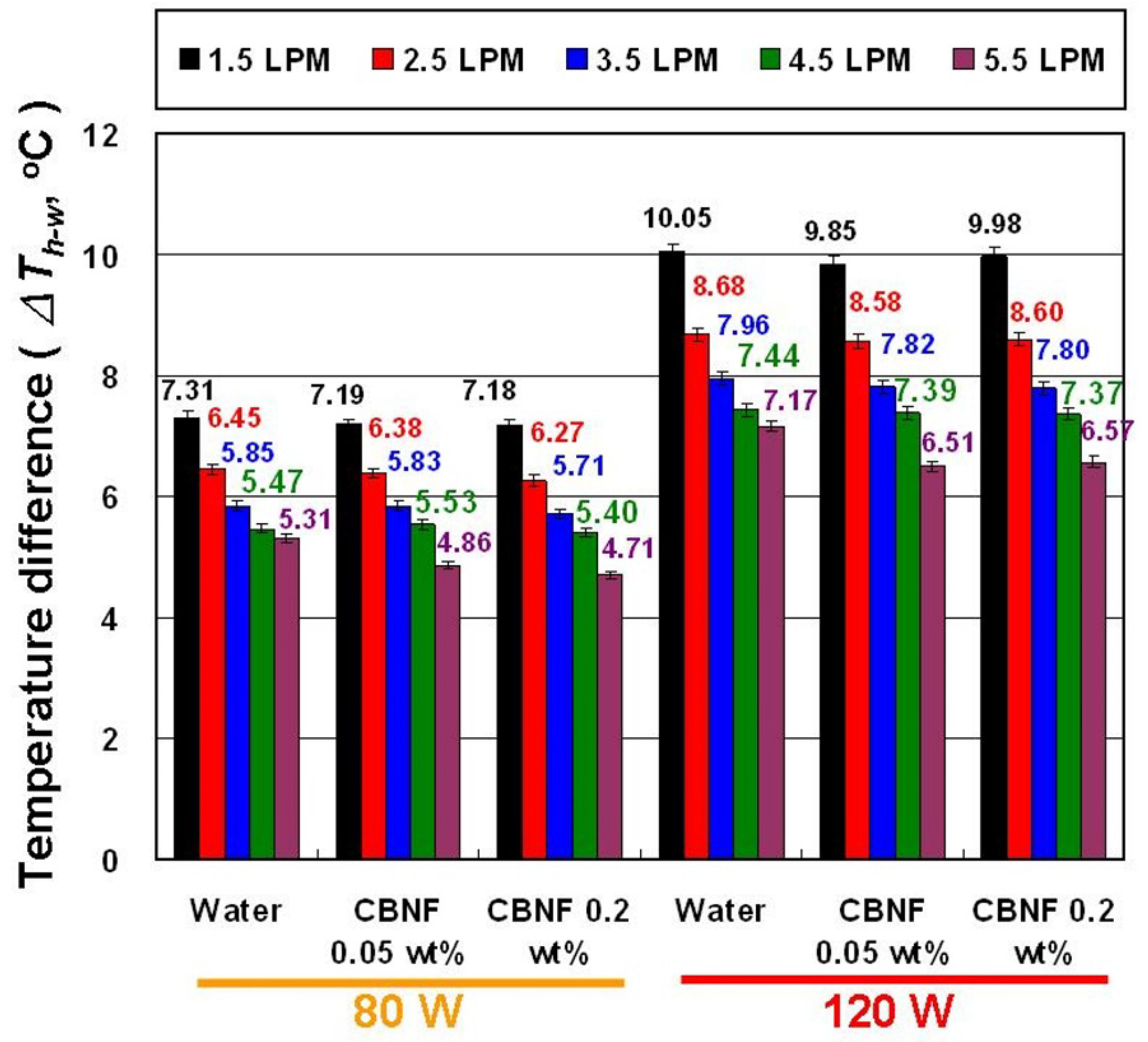
  • CBNFs can reduce the Th under the same experimental parameters, and a lower heater temperature helps to extend the service life of the heater.
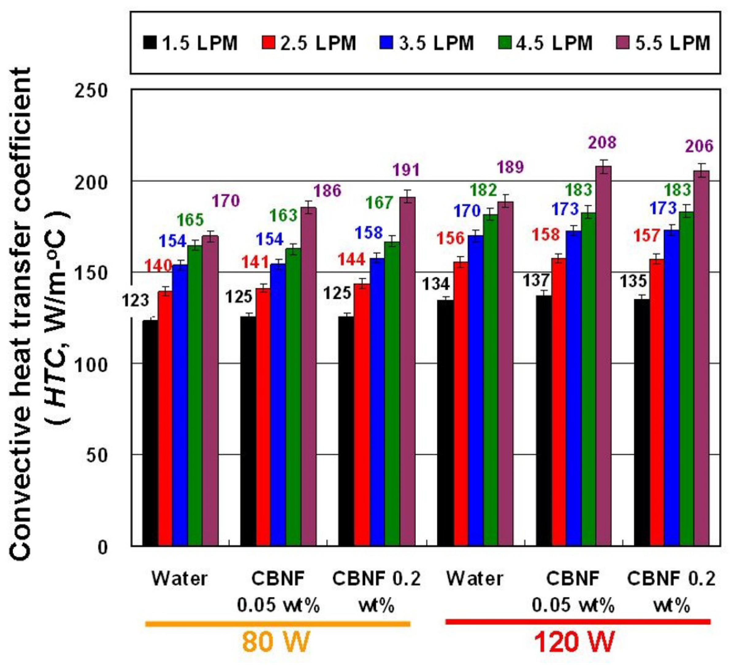
  • The results cumulatively indicate that CBNFs in the THE can lead to a higher HTC than water. In the optimal condition, the average HTC of 0.05 wt% CBNFs at 120 W heating power was about 3.33% higher than that of water, and the average HTC of 0.2 wt% CBNFs at 80 W heating power was about 4.52% higher than that of water.
  • Estimation of PIe indicates that 0.05 wt% CBNF has better system efficiency than 0.2 wt% CBNF and is thus more suitable for the THE system.

Author Contributions

Conceptualization, S.-P.Y., Y.-F.L., and T.-P.T.; designed the experiment, S.-P.Y., Y.-F.L., and T.-P.T.; carried out the measurements, S.-P.Y., T.-P.T., H.-K.H., and C.-C.H.; analyzed the measurements, S.-P.Y. and T.-P.T.; wrote and revised the paper, T.-P.T. All authors have read and agreed to the published version of the manuscript.

Funding

Ministry of Science and Technology of Republic of China (Taiwan) under contract no. MOST 106-2221-E-003-021-MY3 and MOST 109-2221-E-003-002-.

Institutional Review Board Statement

Not applicable.

Informed Consent Statement

Not applicable.

Data Availability Statement

Data available on request.

Acknowledgments

The authors would like to thank MOST for research support (MOST 108-2731-M-002-001, EM0002) and Y.-Y. Yang and C.-Y. Lin from the Instrument Center at National Taiwan University for TEM measurements.

Conflicts of Interest

The authors declare that they have no competing interests.

Nomenclature

ρ: density (kg/m3)T: temperature (°C)
μ: viscosity (mPa s or Pa s): relative uncertainty (%)
A: area (m2)WP: wet perimeter (m)
Ac: cross-sectional area (m2)ΔP: pressure drop (Pa)
cp: specific heat (kJ/kg °C)ΔT: temperature difference (°C)
Dh: hydraulic diameter (m)ε: measurement deviations (%)
Di: inner diameter of the outer tube (m)
do: outer diameter of internal tube (m)
DT: experimental dataSubscripts
G: volumetric flow rate (m3/s or LPM)avg: average value
HTC: convective heat transfer coefficient (W/m2 °C)CBNFs: carbon-based nanofluids
Pf: flow loss (W)cs: cross-sectional
Phe: heating power (W)h: heater
PIe: performance indexi: inlet of THE
Ppe: power consumption of pump (W)o: outlet of THE
R: percentage differences (%)THE: tube heat exchanger
Re: Reynolds numberw: water
wf: working fluid

References

  1. Abbas, N.; Awan, M.B.; Amer, M.; Ammar, S.M.; Sajjad, U.; Ali, H.M.; Zahra, N.; Hussain, M.; Badshah, M.A.; Jafry, A.T. Applications of nanofluids in photovoltaic thermal systems: A review of recent advances. Physica A 2019, 536, 122513. [Google Scholar] [CrossRef]
  2. Pordanjani, A.H.; Aghakhani, S.; Afrand, M.; Mahmoudi, B.; Mahian, O.; Wongwises, S. An updated review on application of nanofluids in heat exchangers for saving energy. Energy Conv. Manag. 2019, 198, 111886. [Google Scholar] [CrossRef]
  3. Esfe, M.H.; Bahiraei, M.; Hajbarati, H.; Valadkhani, M. A comprehensive review on convective heat transfer of nanofluids in porous media: Energy-related and thermohydraulic characteristics. Appl. Therm. Eng. 2020, 178, 115487. [Google Scholar] [CrossRef]
  4. Yang, L.; Ji, W.; Mao, M.; Huang, J.-N. An updated review on the properties, fabrication and application of hybrid-nanofluids along with their environmental effects. J. Clean Prod. 2020, 257, 120408. [Google Scholar] [CrossRef]
  5. Abbas, F.; Ali, H.M.; Shah, T.R.; Babar, H.; Janjua, M.M.; Sajjad, U.; Amer, M. Nanofluid: Potential evaluation in automotive radiator. J. Mol. Liq. 2020, 297, 112014. [Google Scholar] [CrossRef]
  6. Borode, A.O.; Ahmed, N.A.; Olubambi, P.A. A review of heat transfer application of carbon-based nanofluid in heat exchangers. Nano-Struct. Nano-Obj. 2019, 20, 100394. [Google Scholar] [CrossRef]
  7. Ghalandari, M.; Maleki, A.; Haghighi, A.; Shadloo, M.S.; Nazari, M.A.; Tlili, I. Applications of nanofluids containing carbon nanotubes in solar energy systems: A review. J. Mol. Liq. 2020, 313, 113476. [Google Scholar] [CrossRef]
  8. Olabi, A.G.; Abdelkareem, M.A.; Wilberforce, T.; Sayed, E.T. Application of graphene in energy storage device—A review. Renew. Sust. Energ. Rev. 2021, 135, 110026. [Google Scholar] [CrossRef]
  9. Gao, Y.; An, J.; Xi, Y.; Yang, Z.; Liu, J.; Mujumdar, A.S.; Wang, L.; Sasmito, A.P. Thermal conductivity and stability of novel aqueous graphene oxide–Al2O3 hybrid nanofluids for cold energy storage. Appl. Sci. 2020, 10, 5768. [Google Scholar] [CrossRef]
  10. Sani, E.; Vallejo, J.P.; Mercatelli, L.; Martina, M.R.; Rosa, D.D.; Dell’Oro, A.; Lugo, L. A comprehensive physical profile for aqueous dispersions of carbon derivatives as solar working fluids. Appl. Sci. 2020, 10, 528. [Google Scholar] [CrossRef] [Green Version]
  11. Levchenko, I.; Xu, S.; Mazouffre, S.; Lev, D.; Pedrini, D.; Goebel, D.; Garrigues, L.; Taccogna, F.; Bazak, K. Perspectives, frontiers, and new horizons for plasma-based space electric propulsion. Phys. Plasmas 2020, 27, 020601. [Google Scholar] [CrossRef] [Green Version]
  12. M’hamed, B.; Che Sidik, N.A.; Akhbar, M.F.A.; Mamat, R.; Najafi, G. Experimental study on thermal performance of MWCNT nanocoolant in Perodua Kelisa 1000cc radiator system. Int. Commun. Heat Mass Transf. 2016, 76, 156–161. [Google Scholar] [CrossRef]
  13. Selvam, C.; Mohan Lal, D.; Harish, S.; Lal, D.M.; Harish, S. Enhanced heat transfer performance of an automobile radiator with graphene based suspensions. Appl. Therm. Eng. 2017, 123, 50–60. [Google Scholar] [CrossRef]
  14. Martin, E.; Contreras, C.; Oliveira, A.; Pedone, E.; Filho, B. Experimental analysis of the thermohydraulic performance of graphene and silver nanofluids in automotive cooling systems. Int. J. Heat Mass Transf. 2019, 132, 375–387. [Google Scholar]
  15. Teng, T.-P.; Cheng, C.-M.; Yu, S.-P. Evaluation of heat-exchange performance of carbon-based nanofluids for air-cooled exchangers with different cross-section shapes. Appl. Therm. Eng. 2020, 179, 115725. [Google Scholar] [CrossRef]
  16. Ghozatloo, A.; Rashidi, A.; Shariaty-Niassar, M. Convective heat transfer enhancement of graphene nanofluids in shell and tube heat exchanger. Exp. Therm. Fluid Sci. 2014, 53, 136–141. [Google Scholar] [CrossRef]
  17. Esfahani, M.R.; Languri, E.M. Exergy analysis of a shell-and-tube heat exchanger using graphene oxide nanofluids. Exp. Therm. Fluid Sci. 2017, 83, 100–106. [Google Scholar] [CrossRef]
  18. Fares, M.; AL-Mayyahi, M.; AL-Saad, M. Heat transfer analysis of a shell and tube heat exchanger operated with graphene nanofluids. Case Stud. Therm. Eng. 2020, 18, 100584. [Google Scholar] [CrossRef]
  19. Goodarzi, M.; Amiri, A.; Goodarzi, M.S.; Safaei, M.R.; Karimipour, A.; Languri, E.M.; Dahari, M. Investigation of heat transfer and pressure drop of a counter flow corrugated plate heat exchanger using MWCNT based nanofluids. Int. Commun. Heat Mass Transf. 2015, 66, 172–179. [Google Scholar] [CrossRef]
  20. Kumar, V.; Tiwari, A.K.; Ghosh, S.K. Effect of variable spacing on performance of plate heat exchanger using nanofluids. Energy 2016, 114, 1107–1119. [Google Scholar] [CrossRef]
  21. Vasconcelos, A.A.; Cardenas Gomez, A.O.; Bandarra Filho, E.P.; Parise, J.A.R. Experimental evaluation of SWCNT-water nanofluid as a secondary fluid in a refrigeration system. Appl. Therm. Eng. 2017, 111, 1487–1492. [Google Scholar] [CrossRef]
  22. Wang, Z.; Wu, Z.; Sunden, B. Effects of graphene ethylene glycol/water nanofluids on the performance of a brazed plate heat exchanger. J. Nanofluids 2018, 7, 1069–1074. [Google Scholar] [CrossRef]
  23. Bhattad, A.; Sarkar, J.; Ghosh, P. Experimentation on effect of particle ratio on hydrothermal performance of plate heat exchanger using hybrid nanofluid. Appl. Therm. Eng. 2019, 162, 114309. [Google Scholar] [CrossRef]
  24. Esfe, M.H.; Saedodin, S.; Mahian, O.; Wongwises, S. Heat transfer characteristics and pressure drop of COOH-functionalized DWCNTs/water nanofluid in turbulent flow at low concentrations. Int. J. Heat Mass Transf. 2014, 73, 186–194. [Google Scholar] [CrossRef]
  25. Arzani, H.K.; Amiri, A.; Kazi, S.N.; Chew, B.T.; Badarudin, A. Experimental investigation of thermophysical properties and heat transfer rate of covalently functionalized MWCNT in an annular heat exchanger. Int. Commun. Heat Mass Transf. 2016, 75, 67–77. [Google Scholar] [CrossRef]
  26. Poongavanam, G.K.; Panchabikesan, K.; Murugesan, R.; Duraisamy, S.; Ramalingam, V. Experimental investigation on heat transfer and pressure drop of MWCNT—Solar glycol based nanofluids in shot peened double pipe heat exchanger. Powder Technol. 2019, 345, 815–824. [Google Scholar] [CrossRef]
  27. Oliveira, G.A.; Cardenas Contreras, E.M.; Bandarra Filho, E.P. Experimental study on the heat transfer of MWCNT/water nanofluid flowing in a car radiator. Appl. Therm. Eng. 2017, 111, 1450–1456. [Google Scholar] [CrossRef]
  28. Goshayeshi, H.R.; Safaei, M.R.; Goodarzi, M.; Dahari, M. Particle size and type effects on heat transfer enhancement of Ferro-nanofluids in a pulsating heat pipe. Powder Technol. 2016, 301, 1218–1226. [Google Scholar] [CrossRef]
  29. Bahiraei, M.; Jamshidmofid, M.; Goodarzi, M. Efficacy of a hybrid nanofluid in a new microchannel heat sink equipped with both secondary channels and ribs. J. Mol. Liq. 2019, 273, 88–98. [Google Scholar] [CrossRef]
  30. Teng, T.-P.; Hsiao, T.-C.; Chung, C.-C. Characteristics of carbon-based nanofluids and their application in a brazed plate heat exchanger under laminar flow. Appl. Therm. Eng. 2019, 146, 160–168. [Google Scholar] [CrossRef]
  31. Hung, Y.-H.; Wang, W.-P.; Hsu, Y.-C.; Teng, T.-P. Performance evaluation of an air-cooled heat exchange system for hybrid nanofluids. Exp. Therm. Fluid Sci. 2017, 81, 43–55. [Google Scholar] [CrossRef]
  32. Teng, T.-P.; Hsiao, T.-C.; Chung, C.-C. Preparation and experimental evaluation of phase-change characteristics in carbon-based suspensions. Materials 2018, 11, 1315. [Google Scholar] [CrossRef] [Green Version]
  33. Cheng, C.-M.; Yu, S.-P.; Teng, T.-P. Fabrication and characterization of carbon-based nanfluids through water vortex trap method. J. Nanomater. 2018, 2018, 3264621. [Google Scholar] [CrossRef] [Green Version]
  34. Teng, T.-P.; Yu, S.-P.; Hsiao, T.-C.; Chung, C.-C. Study on the phase-change characteristics of carbon-based nanofluids. J. Nanomater. 2018, 2018, 8230120. [Google Scholar] [CrossRef] [Green Version]
  35. Teng, T.-P.; Hsu, Y.-C.; Wang, W.-P.; Fang, Y.-B. Performance assessment of an air-cooled heat exchanger for multiwalled carbon nanotubes-water nanofluids. Appl. Therm. Eng. 2015, 89, 346–355. [Google Scholar] [CrossRef]
  36. Goodarzi, M.; Toghraie, D.; Reiszadeh, M.; Afrand, M. Experimental evaluation of dynamic viscosity of ZnO–MWCNTs/engine oil hybrid nanolubricant based on changes in temperature and concentration. J. Therm. Anal. Calorim. 2019, 136, 513–525. [Google Scholar] [CrossRef]
Figure 1. A schematic diagram of the THE.
Applsci 11 08139 g001
Figure 2. Experimental samples: (a) TEM images of CBNMs; (b) actual photograph of CBNFs.
Applsci 11 08139 g002
Figure 3. System diagram of heat transfer experiments of THE.
Applsci 11 08139 g003
Figure 4. The Re of test samples for THE at various experimental parameters.
Applsci 11 08139 g004
Figure 5. The Pf of test samples for THE at various experimental parameters.
Applsci 11 08139 g005
Figure 6. The Ppe of test samples for THE system at various experimental parameters.
Applsci 11 08139 g006
Figure 7. The Th of test samples for THE at various experimental parameters.
Applsci 11 08139 g007
Figure 8. The ΔTh-w of test samples for THE at various experimental parameters.
Applsci 11 08139 g008
Figure 9. The HTC of test samples for THE at various experimental parameters.
Applsci 11 08139 g009
Figure 10. The PIe of test samples for THE system at various experimental parameters.
Applsci 11 08139 g010
Table 1. List of experimental results on the use of CBNFs in different heat exchangers.
Materials/BFsConcentrationsHE TypesMain FindingsRef.
MWCNTs/EG-W (1:1, v/v)0.1, 0.25, and 0.5 vol%Vehicle radiatorHTC was proportional to flow rate (G), Re, and MWCNTs concentration.
Maximum enhancements of HTC was 196.3% at 0.5 vol% NF at Re of 1400.
[12]
GNP/EG-W (3:7, v/v)0.1–0.5 vol%Automobile radiatorHTC was proportional to GNP concentration, inlet temperature (Ti), and mass flow rate (mwf).
A maximum enhancement of HTC was 51% for 0.5 vol% NF at mwf of 100 g/s and Ti of 45 °C.
Maximum pressure drop (ΔP) was 4.80 kPa for 0.5 vol% NF at Ti of 35 °C and mwf of 100 g/s.
[13]
GN/EG-W (1:1, v/v)0.01, 0.05 and 0.1 vol%Automobile radiatorA maximum enhancement of heat exchange rate was 3.3% at 0.1 vol% NF and Ti of 85 °C.
The heat exchange rate of 0.01 vol% and 0.05 vol% NF was lower than BF.
[14]
CBNMs/W0.01 and 0.05 wt%Rectangular (R) and circular (C) tubes ACHEA maximum improvement of heat exchange capacity was 8.17% at 0.05 wt% NF at G of 2.0 LPM and Ti of 40 °C for R-ACHE.
A maximum enhancement of heat exchange capacity was 4.88% at 0.01 wt% NF at G of 2.5 LPM and Ti of 40 °C for C-ACHE.
0.01 wt% NF had higher system efficiency.
[15]
GN/W0.025–0.1 wt%Shell and tube HEThe HTC increased at higher NF concentration and temperature.
A maximum enhancement of HTC was 35.6% at 0.1 wt% NF at fluid temperature of 38 °C.
[16]
GO/W0.01 and 0.1 wt%Shell and tube HEExergy loss of 0.01 wt% and 0.1 wt% NF were 22% and 109% lower than water.
Exergy loss was proportional to the Ti of the NF.
[17]
GN/W0.01, 0.05, 0.1, and 0.2 wt%Vertical shell and tube HEA maximum enhancement of HTC was 29% at 0.2 wt% NF.
Average thermal efficiency of the HE improved by 13.7%.
[18]
SWCNTs/W0–0.21 vol%Brazed PHE in refrigeration systemThe overall thermal performance and refrigerating capacity of the system using NF as the secondary fluid were higher than those of water at the same mwf (40–80 g/s) and Ti (30–40 °C).[21]
GN/EG–W0.01–1.0 wt%Brazed PHE in the hot fluid sideGN NF from 0.01 to 0.1 wt% significantly enhanced the HE performance and created a slight ΔP in the PHE.
HTC improvement was about 4–7% for the different NF concentrations.
[22]
Al2O3-MWCNTs/ Wvol%
Al2O3: MWCNTs (5:0, 4:1, 3:2, 2:3, 1:4, and 0:5, v/v)
PHEThe optimal overall performance is MWCNTs NF (0:5, v/v).
HTC improvement was15.2%.
Pump power elevated by 0.02%, and the performance index enhanced by 2.96%.
[23]
Functionaliz-ed DWCNTs/W0.01–0.4 wt%Double-pipe HEThe enhancement of HTC, the average Nusselt number, and ΔP was 32%, 18%, and 20% for 0.4 wt% NF, respectively.[24]
Functionaliz-ed MWCNTs/W0.025, 0.05, 0.075, and 0.1 wt%Horizontal annular (tube) HEHTC enhancement far exceeded the enhancement in k for NF.
A maximum enhancement of HTC was 22.4% for 0.1 wt% NF at Re of 6807 and heating power of 1200 W.
The mean ΔP was increased to 38% due to higher μ of NF.
[25]
MWCNTs/so-lar glycol0.2, 0.4 and, 0.6 vol%Double pipe HE with a modified inner surfaceA maximum enhancement of HTC was 115% at 0.6 vol% NF at mwf of 0.04 kg/s.
ΔP increased 1.56 times at mwf of 0.08 kg/s.
Modified inner surface (shot peening process) significantly affected on flow behavior and heat exchange rate.
[26]
Table 2. List of μ and ρ for working fluids.
ItemTemp. (°C)WaterCBNF
0.05 wt%
CBNF
0.2 wt%
ρ
(kg/m3)
30996.63997.08997.94
40993.24993.45994.25
50989.02988.81989.99
60984.28983.52984.62
μ
(mPa-s)
300.800.880.90
400.700.780.82
500.650.680.70
600.550.580.60
Publisher’s Note: MDPI stays neutral with regard to jurisdictional claims in published maps and institutional affiliations.

