1. Introduction
Although the problem of the thermal load of people employed in hot microclimate conditions is known [
1,
2], there is still no solution for an individual cooling system that would comprehensively meet existing needs. Systems using phase change materials (PCMs) are characterized by a limited operation time, depending on the transition time, as well as a relatively low efficiency that is tightly connected to the incorporated weight of PCMs [
3]. In the case of air cooling systems, either air fans [
4] or compressed air bottles [
2] are used. However, the former provide only ventilation (the air is not cooled), while the latter are heavy, causing a significant additional load. Liquid cooling requires a separate cooling unit with a compressor that limits workers’ mobility [
1]. On the other hand, thanks to the significant miniaturization and technological progress observed in recent years in the field of wearable electronics, the use of thermoelectric coolers (TECs) for the considered purpose seems to be a promising direction.
TECs are based on the thermoelectric or Peltier effect, which occurs when two materials with different thermoelectric coefficients are combined [
5]. TEC devices consist of a number of alternately arranged pairs of n- and p-type semiconductors sandwiched between two, most often ceramic, plates that conduct heat but are electrical insulators [
6]. Such a pair of n- and p-type semiconductors that are connected electrically in series and thermally in parallel is termed a thermoelectric module [
7] or a Peltier module.
Cooling with the use of thermoelectric modules has many advantages over conventional cooling methods, particularly for use by humans in portable equipment. Thermoelectric module systems tend to be lighter in weight and smaller in size [
8]. Moreover, they generate no noise and do not use toxic chemical refrigerants such as freon [
9]. Moreover, a TEC can act not only as a cooling device but also as a heating device, with switching between the two modes being easy to achieve [
7]. The research described in the literature shows that cooling systems based on the thermoelectric phenomenon are able to stabilize the microclimate temperature under clothing during physical activity, which confirms the effectiveness of their operation [
10]. In addition, the reliance on electronic solutions provides the ability to easily monitor and control the temperature in the microclimate under clothing to ensure thermal comfort [
11]. Therefore, protective clothing with TEC modules can also be used in a smart working environment as one of the Internet of Things solutions.
There are reports in the scientific literature in which TEC modules have found practical application in clothing with a cooling function. An example of such use is the jacket developed by Lavanya et al. (2016) [
7]. In this jacket, the links are used as an element that receives heat from the liquid that cools the user’s body through a system of pipes distributed on the inside of the garment. A very interesting solution is also a jacket that allows both cooling and heating of the user’s body depending on the user’s needs, developed by Poikayil et al. (2017) [
11]. It is a battery-powered system with a built-in temperature sensor that measures the internal temperature of the vest; the cooling and heating effects are ensured by traditional Peltier modules with fans in the jacket. Clothing with a cooling function using highly efficient flexible thermoelectric coolers was developed by Hong et al. (2019) [
12]. The authors proposed a vest and a headband to be used directly on the body. The proposed solution is characterized by a small size, high flexibility, and low weight (0.56 g/cm
2) and has the potential to reduce electricity consumption compared to collective air-conditioning devices. These reports indicate that the use of thermoelectric modules in cooling clothing is a promising direction of research; however, the use of flexible TEC modules for this purpose is still limited. Standard Peltier cells, due to the ceramics, are hard and brittle [
13]; therefore, they are not a good solution when the flexibility of the cooling device is an important feature. The proposed clothing where flexible TEC modules have been used does not include heat sinks, which limits its potential to applications such as sports, in which cooling is required primarily due to intensive physical activity, not high ambient temperature. In a hot environment, such a solution will be ineffective.
Taking the above into account, an analysis of the possibility of using flexible thermoelectric coolers in protective clothing to collect excess heat from the human body while working in a hot microclimate (e.g., in the construction sector) was conducted. This publication presents the results of this analysis in terms of the influence of such factors as supplied current, ambient temperature, and the type of heat sink on the amount of heat flux transferred by the selected TEC and the electric power consumed by it. The results obtained will be the basis for further research work aimed at the development of a protective clothing with TECs ensuring thermal comfort in the work environment.
2. Materials and Methods
2.1. Tested Object
The technology of flexible thermoelectric modules is currently under development [
14]. In the course of the market analysis performed, only one manufacturer offering commercial flexible thermoelectric modules was identified: the TEGway company (
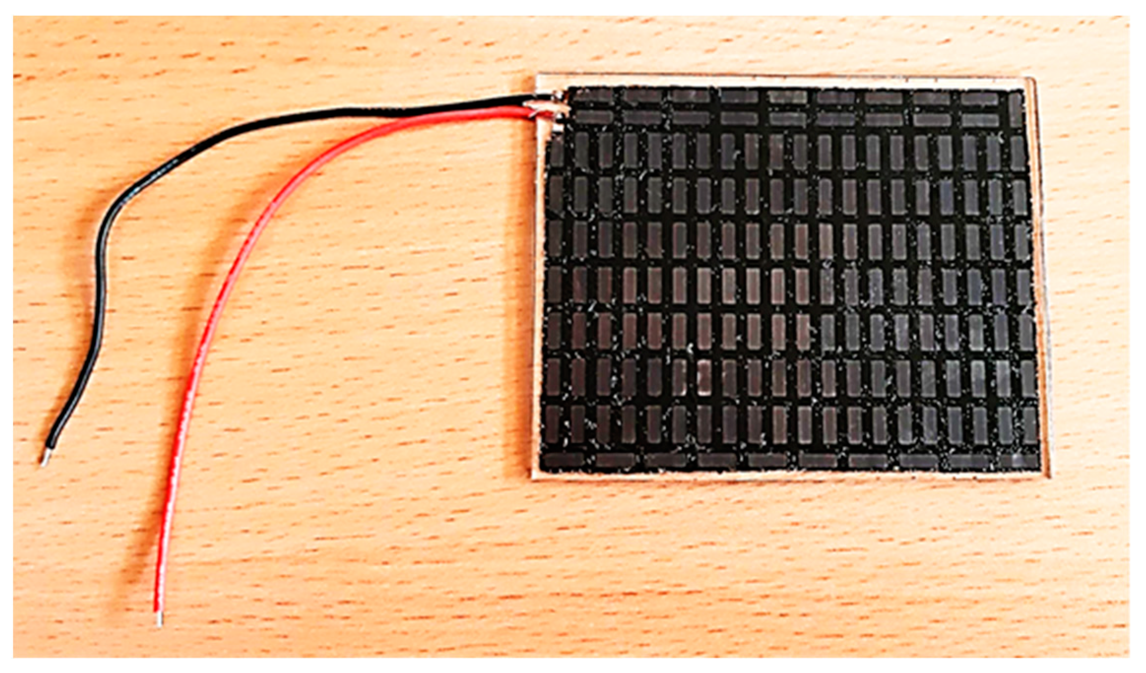
http://tegway.co accessed on 24 August 2021). TEGway modules are made of many small-area elementary cells based on bismuth and tellurium (BiTe). These elementary cells are connected electrically and mechanically by a filling made of flexible plastic. This results in their parallel connection in the thermal domain and their series connection in the electrical domain. The FTE1-01 module (
Figure 1) was selected for the laboratory tests, with dimensions of 68 mm × 85 mm × 2.3 mm, a fill factor (ratio of the active area to the total TEC area) of 17%, a number of elementary cells of 169, a maximum heat flux of 76.5 W, and a maximum temperature difference of 60.8 °C. The decisive choice criteria were the fill factor and the size of the active surface as compared to other modules offered [
15].
The key to ensuring effective cooling by a TEC module is the appropriate selection of a heat sink receiving heat from the hot side of the TEC. For the selected flexible thermoelectric modules FTE1-01, it was decided to use three heat sink variants: two dedicated for these specific modules—a metal and a polymer one—and another polymer one, designed within the research project.
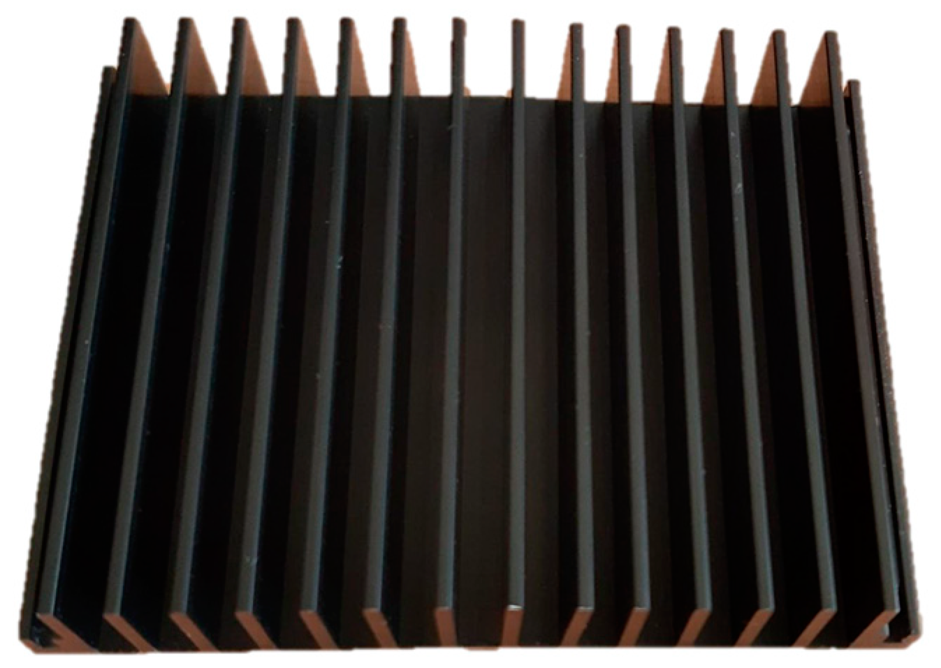
The metal heat sink (
Figure 2) has a weight of 67.54 g and dimensions of 89 mm × 68 mm × 15 mm. It is stiff, but due to its thin base, it can be bent in one direction, and after removing the force, the element does not return to its original form. The heatsink height of 15 mm makes its practical use in cooling garments limited; however, the decision was made to use it in tests for comparison purposes.
The TEGway polymer heat sink (
Figure 3) is flexible in all directions. Its weight is much lower than that of a metal heat sink, amounting to approx. 7.58 g. The dimensions of this heat sink are 117 mm × 95 mm × 1.50 mm when dry. This element uses the evaporation effect to receive heat from a TEC. Before using this element, the manufacturer recommends soaking it in water for a few minutes and then squeezing it lightly so that water does not flow out of it during use. When wet, the heat sink absorbs moisture, increasing its weight and thickness.
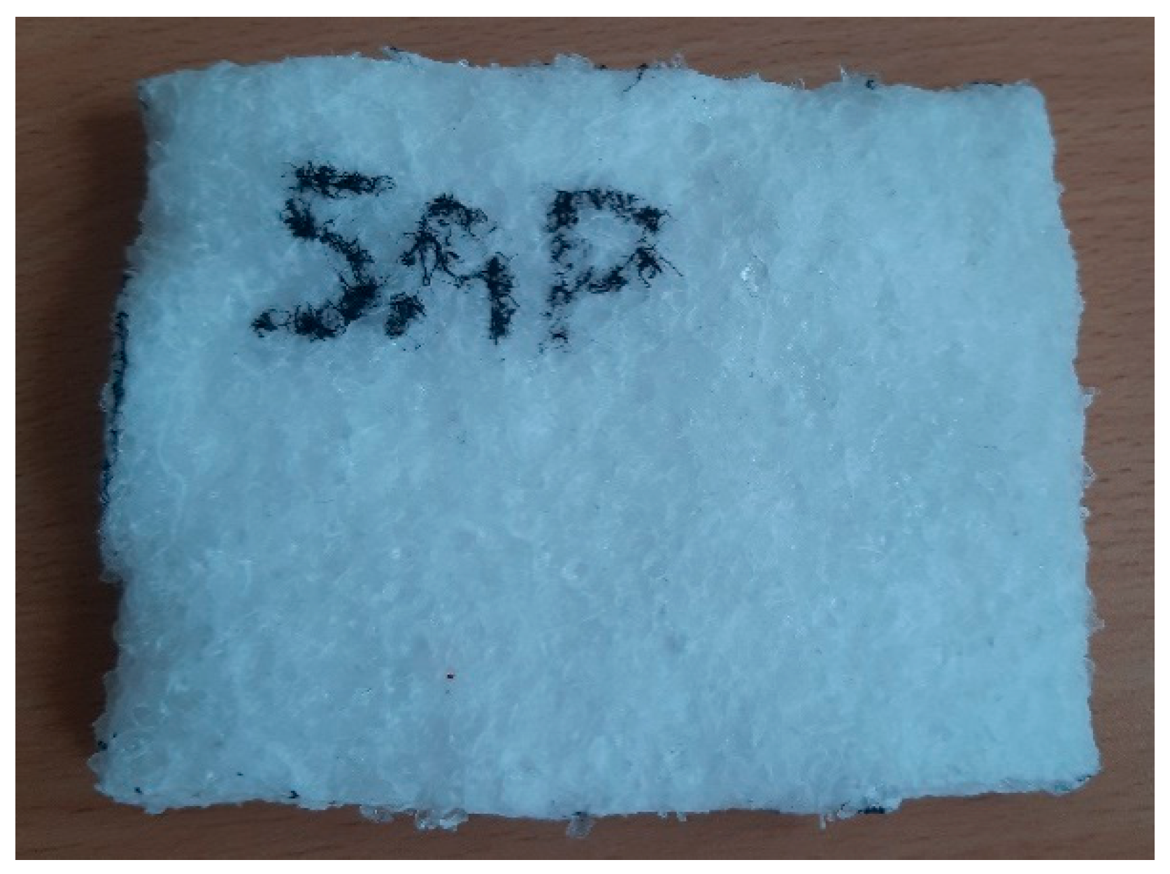
In order to carry out the laboratory tests, an attempt was also made to develop an own heat sink using a non-woven fabric with superabsorbents (SAPs). This heat sink was made of melt-blown non-woven polypropylene fibers with 14% superabsorbent powder with an area weight of 84 g/m
2 (
Figure 4). For its production, 5 layers of the above-mentioned non-woven fabric were used, which were inserted between the Pontetorto polyester knit (backsheet) and the Toray polyamide fabric (topsheets). The resulting heat sink has dimensions of 117 mm × 95 mm × 6 mm, and its dry weight is 7.66 g. The area is therefore the same as for the TEGway polymer heat sink, while the thickness is determined by the number of layers of melt-blown non-woven fabric used, which in turn was selected so that the total dry weight was similar to the weight of the TEGway polymer heat sink.
The variants selected for the laboratory tests are listed in
Table 1.
2.2. Testing Methodology
2.2.1. Research Apparatus
In order to carry out laboratory tests of the selected combinations of flexible thermoelectric modules and heat sinks, it was necessary to develop a completely new research methodology, which included measurements of thermal and electrical parameters. It was decided to use the test stand called the “skin model.” This stand is equipped with an electrically heated plate controlled so as to keep its temperature constant, which enables measuring thermal parameters of materials. The uncertainty of the measurement of the heat flux is equal to 2%. This “skin model” is placed in the WEISS WK11 340 microclimate chamber, which provides constant and controlled climatic conditions during measurements. To ensure the possibility of measuring electrical parameters, the measuring system of the “skin model” stand was additionally equipped with the following elements:
ITECH IT6942A laboratory power supply;
a voltmeter (Amprobe 33XR-A multimeter set to measure DC voltage);
an ammeter (Amprobe 33XR-A multimeter set to measure DC current);
pairs of wires for TEC powering (ended with banana plugs);
pairs of wires for measuring TEC voltage (ended with banana plugs);
a terminal block for connecting the pairs of wires to the factory-made wires of the tested TEC.
The voltage and current measurement ranges had to be adjusted to the values observed in the measurement setup: 4 V and 300 mA. The respective measurement uncertainties are: ±(1% + 1 mV) and ±(1.5% + 0.4 mA).
Two pairs of wires were used to connect the meters in a four-wire system to eliminate measurement error related to the voltage drop on the pair of wires that conduct the TEC supply current. One pair was applied to power the TEC under test, while the other, to measure the voltage. The small voltage drop appearing on the short sections of factory-made cables (between the terminal block and the TEC) was taken into account and subtracted when processing the measurement results.
2.2.2. Research Conditions
Thermoelectric modules were tested on the heating plate with a constant temperature of 35 °C in an environment in which the temperature varied from 20 to 35 °C every 5 °C, with a relative humidity of 70%, and an air velocity of 1 m/s. Tests conducted at the ambient temperature of 35 °C corresponded to isothermal conditions, while tests conducted at other ambient temperatures corresponded to non-isothermal conditions. In the latter case, apart from the heat exchange between the heating plate and the TEC, heat was also exchanged directly between the heating plate and the environment, which had to be taken into account when processing results.
When considering an application in clothing, the electrical safety of the user must be ensured. As there is no specific standard enforced for protective clothing, one must rely on general guidelines. Useful information on the effect of voltage and current on human beings may be found in the IEC 60479-1 standard [
16], although it is not intended to be directly applied by manufacturers. The safety analysis was performed for the hand-to-chest path, which is the most restrictive one. The Peltier modules are not supposed to be in direct contact with the skin in normal conditions, as they will be separated with a non-conductive fabric. Nevertheless, such contact may occur due to, e.g., fabric tear or wear, when the touching area may be expected not to exceed 1 cm
2. By their operating principle, Peltier modules must be supplied with a DC voltage. It follows from [
16] that under these assumptions, the voltage threshold of reaction equals 42.5 V, which value is commonly accepted as the Safety Extra-Low Voltage [
17]. However, it should be taken into account that in a hot environment, the user may sweat. For this reason, while the value of 42.5 V applies to general wet conditions, a more restrictive limit of 7.3 V should rather be applied to protective clothing for hot environments, the latter value corresponding to salt-wet conditions. Consequently, the voltage limit set in this research was 7.2 V.
2.2.3. Measured Parameters
Laboratory tests included the measurement of both thermal and electrical parameters. In terms of thermal parameters, the focus was primarily on the thermal power supplied to the “skin model” heating plate necessary to maintain its constant temperature at 35 °C in specific climatic conditions. This power was then converted into the heat flux transferred by the cooling system together with the heat sink using the equation:
where:
Pc—heat flux transferred by the cooling system (TEC with a heat sink) at a given electric power and in given climatic conditions, W;
Pz—thermal power supplied to the heating plate to keep its temperature constant at a given electric power supplied to the TEC in given climatic conditions, W;
P0—thermal power supplied to the heating plate with the TEC power supply turned off, thus corresponding to the heat exchanged directly between the plate and the environment, W.
In the case of isothermal tests, the direct heat flux from the plate to the environment was 0 W; therefore, the heat flux transferred by the TEC system was identical to the thermal power supplied to the heating plate.
In terms of electrical parameters, during the tests, TEC current and voltage were measured, which were then used to determine the electric power using the equations:
where:
Pe—electric power, W;
Ur—actual TEC voltage, taking into account the resistance of electric wires, V;
I—TEC current, A;
U—measured voltage, V;
Rw—common (factory-made) wire resistance, 15.6 mΩ.
The related measurement uncertainty of power is, therefore, a function of the uncertainties of the voltage and current meters given in
Section 2.2.1. It can be approximated with:
for the relative part, where ∆U
rel/U and ∆I
rel/I are the relative parts of uncertainties of the voltmeter and of the ammeter, respectively; and with
for the absolute part, where ∆U
abs and ∆I
abs are the absolute parts of uncertainties of the voltmeter and of the ammeter, respectively.
The measurement error related to the Rw × I term may be neglected, as the common wire resistance Rw is much smaller than the Pelter module resistance (which is of the order of several ohms) to which the U term is proportional.
2.2.4. Research Variants
As a part of the developed methodology, the research was planned to be carried out for a total of 24 variants, with 4 repetitions of each measurement. A detailed list of variants selected for the study is presented in
Table 2.
2.2.5. Research Procedure
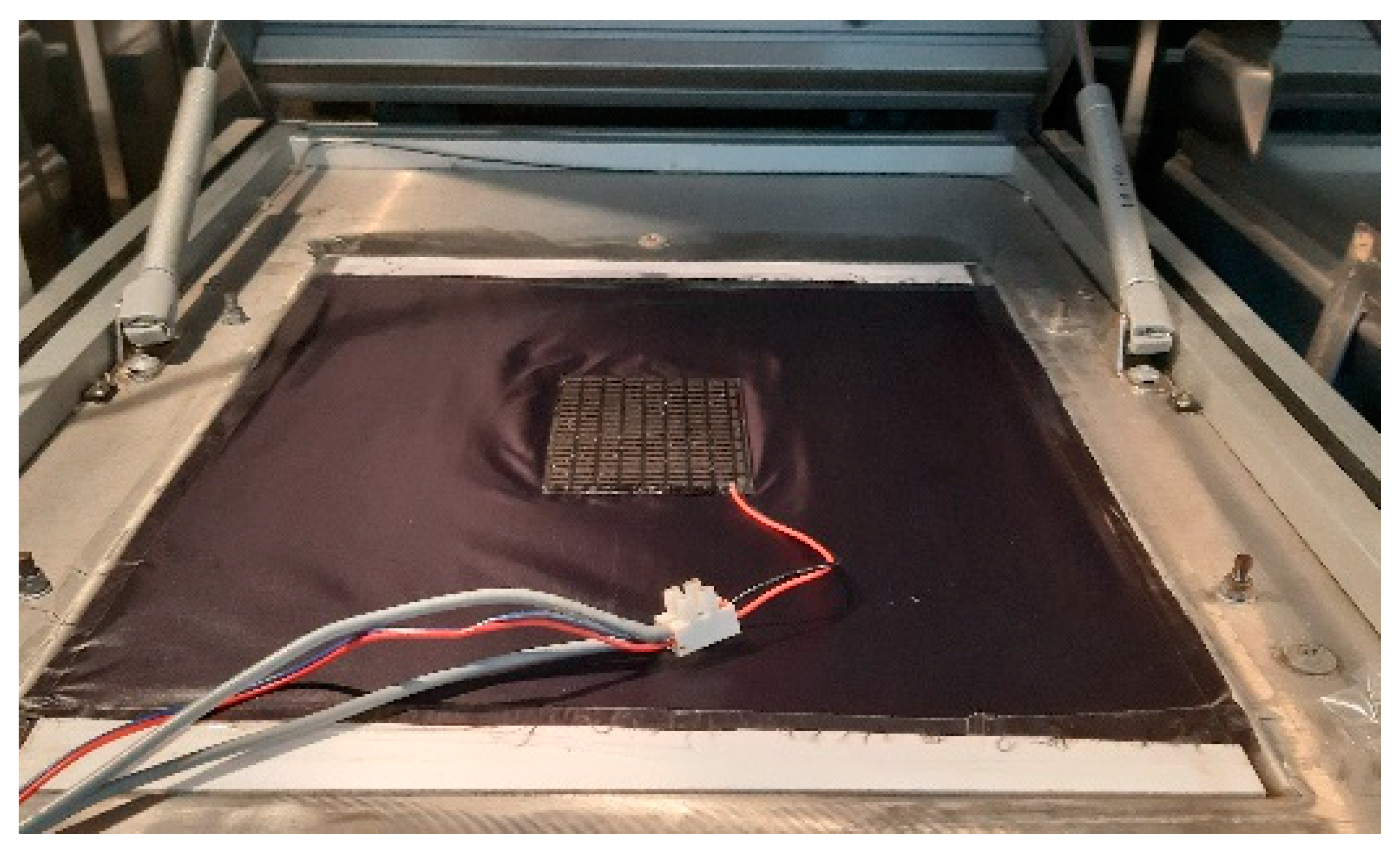
Before starting the tests, the Toray fabric was placed on the heating plate of the “skin model” in order to electrically isolate the TEC module from the heating plate of the “skin model.” At the same time, such test conditions corresponded to the conditions of the final use, where TEC modules used in a clothing will not be in direct contact with the user’s skin. Then, the TEC under test was connected to the terminal block and placed in the center of the heating plate, with the cold side of the module facing the plate (
Figure 5).
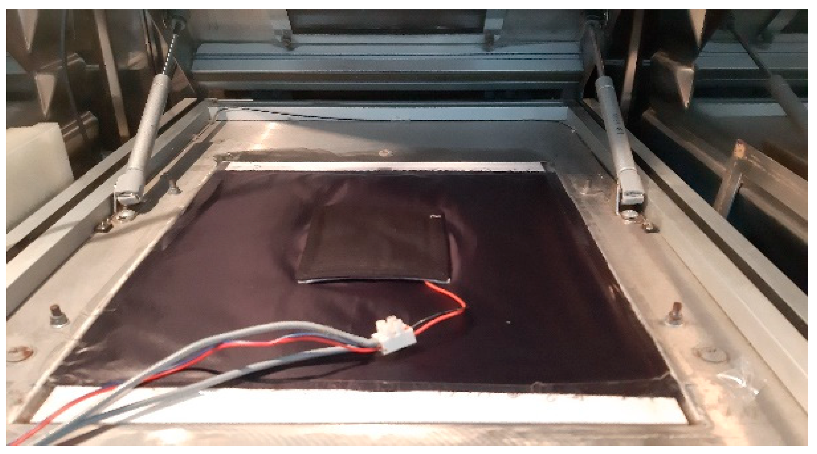
The further procedure depended on the type of heat sink used. In the case of tests with the use of the TEGway polymer heat sink (
Figure 6) or the self-made heat sink with SAP, after placing the module on the “skin model,” the climate chamber was closed, the appropriate setting of the climatic conditions was made, and it was waited until the conditions in the chamber stabilized, which was indicated by a constant heating power of the plate. During this time, the heat sink was initially prepared, i.e., it was soaked in water at a room temperature of approx. 22 °C until its mass was approx. 50 g (which weight was selected on the basis of preliminary tests of the absorption capacity of heat sinking elements). When the conditions in the climatic chamber were stabilized and the heat sink was soaked, the chamber was opened, the heat sink was placed on the module, the cover of the “skin model” channel was lowered, the climatic chamber was closed, and the TEC power supply was turned on with a current adjusted according to
Table 2. The heat sink was placed directly on the Peltier module in accordance with the manufacturer’s guidelines. These activities were performed as fast as possible in order to minimize their influence on the conditions inside the chamber.
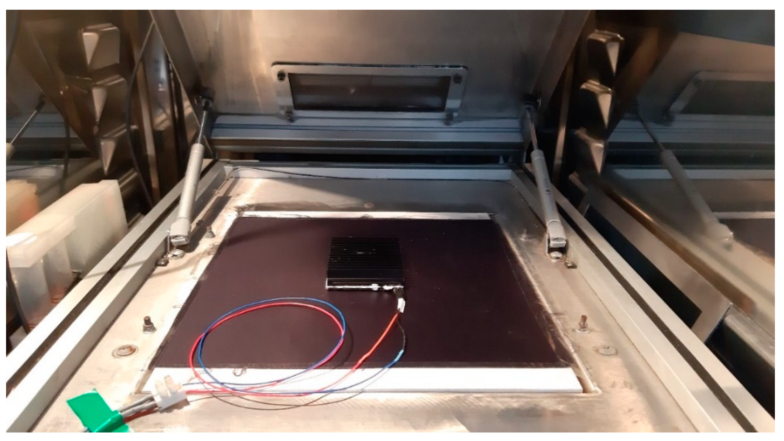
In the case of tests with the use of the metal heat sink (
Figure 7), a layer of thermal paste (AG thermally conductive silicone paste H) was applied to the heat sink, and then it was placed on the module, ensuring a complete adhesion of the heat sink surface to the TEC. On the other hand, no additional electrical insulation was needed, as the metal fingers of the heat sink used were originally mounted on a flexible non-conductive substrate. The flexible TEC and the heat sink thus formed one whole. Due to the above, the stabilization of the test conditions was performed for the TEC combined with the metal heat sink placed in the chamber without supplying the TEC. This was necessary because it was not possible to quickly and evenly attach the heat sink to the TEC module without disturbing the conditions established in the climatic chamber. When the conditions in the chamber were already stabilized, as in the case of heat sinks using the evaporation effect, the power supply was turned on with the appropriately adjusted current level, and the measurement was started.
The setpoint value used to control the electric power supplied to the TEC module was the module current. Due to the effect of the decrease in the power of the heating plate for sufficiently high TEC currents (resulting from the heat dissipation in the TEC module, as discussed in
Section 4), it was necessary to limit the range of the current to a maximum value at which this decrease was still not observed. This value was equal to 0.25 A for the FTE1-01 module and corresponded to a TEC voltage of approximately 1.2 V, which was well below the electrical safety limit of 7.2 V discussed in
Section 2.2.2. For each set of test conditions listed in
Table 2, measurements were repeated several times (four in most cases) to minimize the influence of random errors.
As part of the laboratory tests, additional measurements were performed, in which the TEC was not powered after the conditions stabilized and the chamber was closed. These measurements were carried out in order to separate the power supplied to the heating plate resulting from cooling by the TEC system, i.e., eliminating the direct heat flux from the heating plate to the environment due to the temperature difference between them (Equation (1)). Each measurement lasted approx. 30 min.
2.2.6. Statistical Analysis
The obtained results of the heat flux and electric power tests were subjected to statistical analysis in order to determine the statistical significance of the obtained differences. Before starting the analysis, the normality of the distribution of variables was checked using the Shapiro–Wilk test. Due to the non-fulfillment of the normality criterion, the non-parametric Kruskal–Wallis test was used for the statistical analysis, and in the case of statistically significant differences, the multiple comparison test of mean ranks was applied for their detailed analysis. The test significance level was set at 0.05. The statistical analysis was performed with the use of the STATISTICA 13.1 PL software.
3. Results
3.1. Influence of TEC Current and Heat Sink Type on the Heat Flux and Electric Power
The results of the research on the effect of the TEC current on the amount of heat flux transferred by the FTE1-01 flexible module and on the electric power supplied to it, depending on the heat sink used in isothermal conditions (T = 35 °C), are shown in the graphs below (
Figure 8 and
Figure 9, respectively).
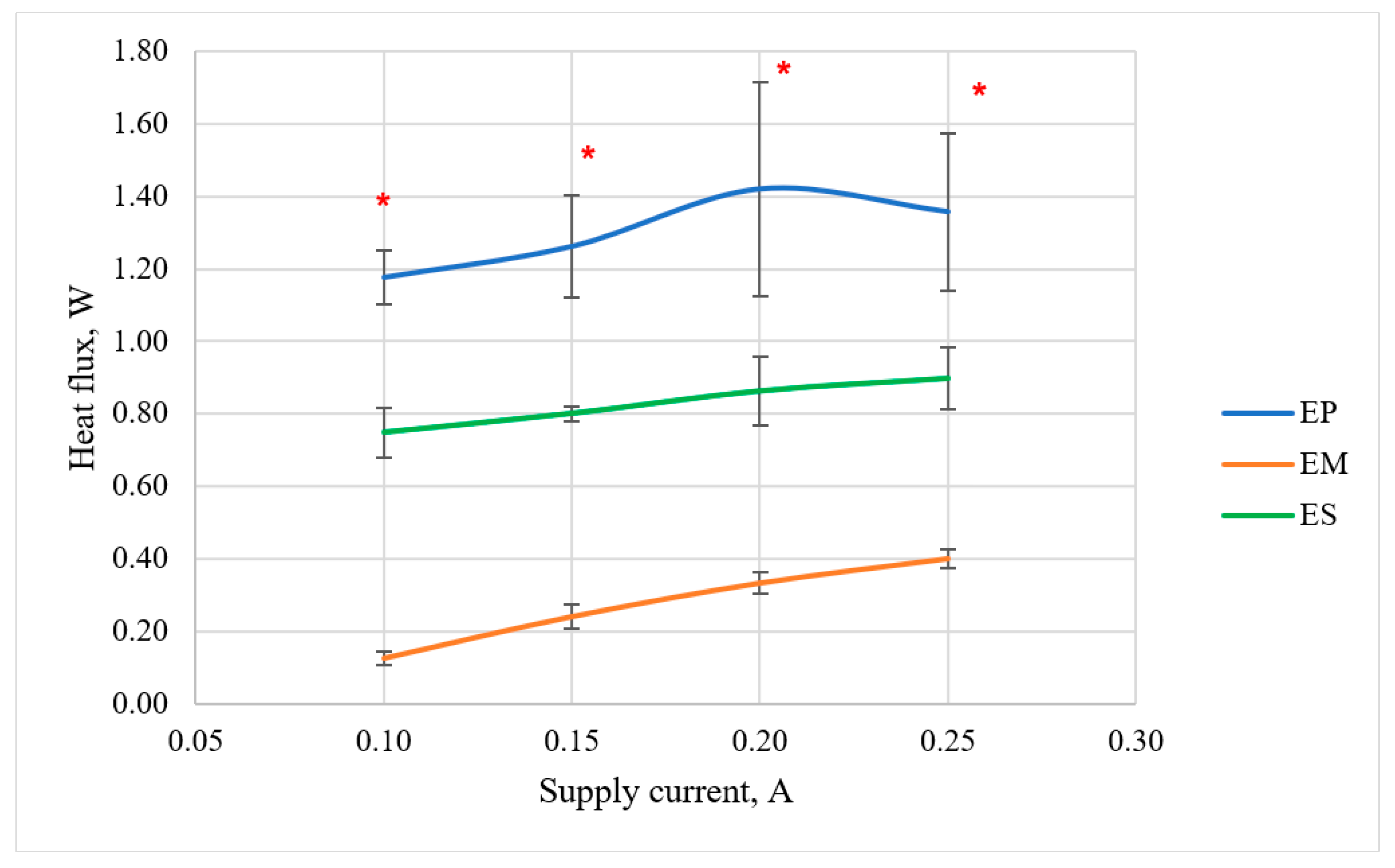
On the basis of
Figure 8, it can be concluded that the dependence of the heat flux on the TEC current is close to linear, except for the EP variant (flexible module with the polymer TEGway heat sink). The performed statistical analysis showed that only in the case of the EM variant (i.e., with the use of the metal heat sink), the effect of increasing the TEC current from 0.1 to 0.25 A was statistically significant. The obtained test results also indicate that the type of heat sink used has a significant impact on the obtained value of the heat flux transferred by the module from the heating plate of the “skin model.” Elements that use the evaporation effect have significantly higher efficiencies. The metal heat sink, which transfers heat to the environment almost exclusively by convection (the radiation mechanism being negligible at the temperatures applied), is much less effective. The observed differences between these variants were statistically significant for each of the analyzed current values. The self-made heat sink with SAP turned out to be less effective than the polymer one provided by TEGway. However, as the research has shown, when assessing heat sinks, the durability of their properties over time should also be taken into account. The TEGway heat sink stopped absorbing moisture after several dozen uses and, consequently, stopped fulfilling its intended function.
As a result of the laboratory tests, the characteristic of the electric power consumed by the FTE1 01 module was also determined as a function of the module supply current (
Figure 9). The measurement uncertainty of this power calculated according to Equations (5,6) was between 2.7% and 3.2%.
This characteristic does not depend on the heat sink used, which is in line with theoretical predictions: it should result only from the electrical properties of the thermoelectric module. This characteristic is parabola-shaped, which indicates the resistive nature of the module according to Joule’s law:
where:
The regression curve in the diagram (
Figure 9) has a coefficient at a power of 2 equal to 4.80 Ω, which is the module resistance. The knowledge of this value will allow to determine the required parameters of the power supply and the control system in the future if this module is selected for the construction of the cooling system.
3.2. Influence of the Ambient Temperature and Heat Sink Type on the Heat Flux and Electric Power
The results of the research into the influence of the ambient temperature and the type of heat sink used on the heat flux transferred by the FTE1-01 flexible module and the electric power supplied to it are presented in the graphs below (
Figure 10 and
Figure 11).
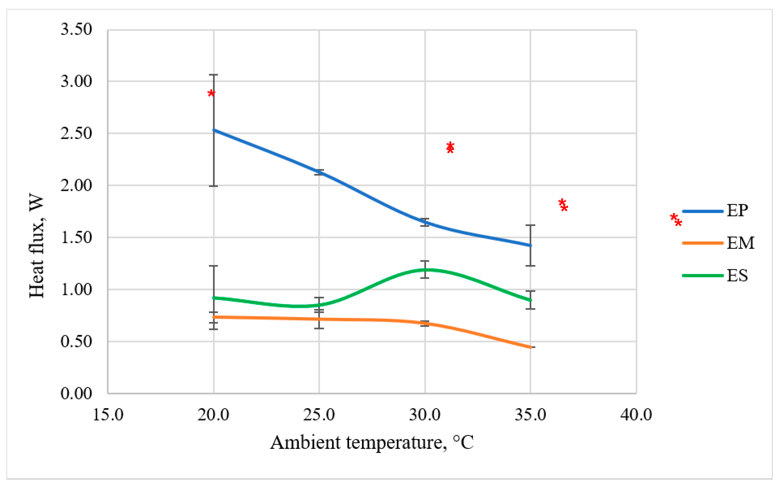
Figure 10 indicates that with the increase in the ambient temperature, a decrease in the heat flux can be observed, which is particularly visible in the EP variant, i.e., with the use of the TEGway polymer heat sink. For this variant, at an ambient temperature of 20 °C, the heat flux was at the level of 2.5 W, while at an ambient temperature of 35 °C, it reached a value of approx. 1.4 W. The performed statistical analysis confirmed the statistically significant influence of the ambient temperature on the heat flux between 20 °C, 25 °C, and 35 °C. It should be noted, however, that even at the ambient temperature of 35 °C, the heat flux obtained with the EP variant was still higher than in the case of other variants at lower temperatures. This result shows that the polymer heat sink proposed by TEGway is able to effectively remove heat from the module’s hot side, thereby increasing its efficiency in removing heat through the TEC module from the “skin model” heating plate. The statistical analysis performed confirmed that the differences observed between the EP and EM variants are statistically significant. On the basis of the obtained test results, it can also be concluded that the difference in heat flux in favor of the polymer heat sink as compared to the metal one becomes greater with the increasing temperature difference between the “skin model” heating plate and the environment.
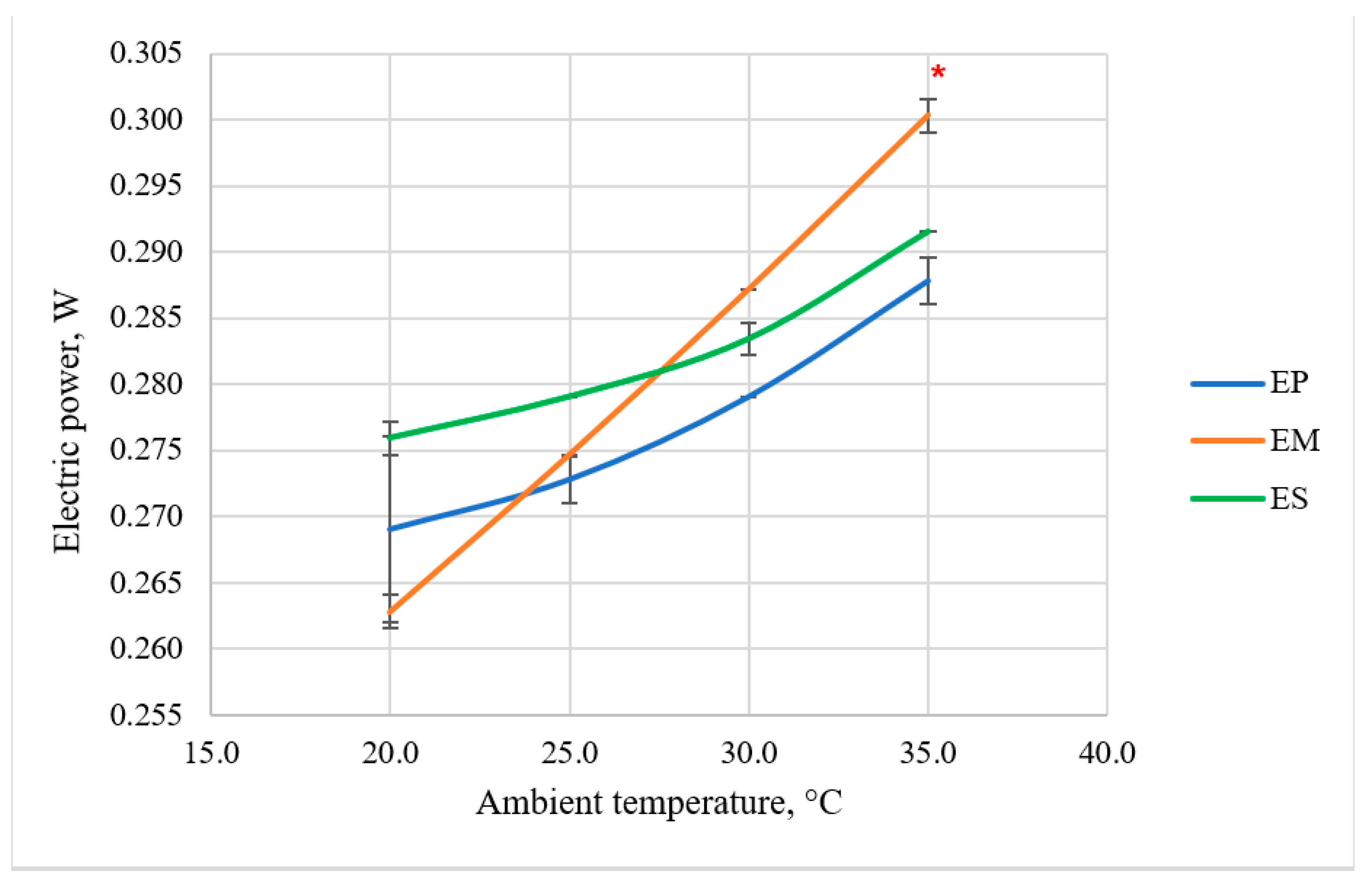
On the basis of
Figure 11, it can be concluded that the ambient temperature and the type of the heat sink also affect the electric power supplied to the TEC at a constant current of 0.25 A (corresponding to a TEC voltage of 1.2 V). Along with the increase in ambient temperature, in all the analyzed variants, the electric power increased. However, in the case of the variant with the TEGway metal heat sink, this relationship was linear. In the case of variants with heat sinks using the evaporation effect (EP and ES), the observed increase in the electric power was slower; only after reaching a temperature of approx. 30 °C was there was a more rapid increase in the electric power consumed. These results indicate that the EP variant, apart from the highest heat flux, requires the lowest electric power in almost all conditions. On the other hand, in the case of the EM variant, except for the ambient temperature of 20 °C, the dependence of the heat flux and electric power on the ambient temperature is the least favorable. In the case of the ES and EM variants, the differences in electric power between the temperatures of 20 °C and 35 °C were statistically significant.
4. Discussion
The conducted laboratory tests confirmed that some of the electric power supplied to the module is released in the form of heat and the nature of this relationship is unfavorable. The heat flux released to the environment is the sum of the heat flux corresponding to cooling and the heat dissipated in the TEG module due to its operation. The power supplied and dissipated in the module grows faster than the heat flux; therefore, the higher the heat flux to be transferred, the greater the share of the heat flux generated by the module itself. As a result, above a certain value of electric power (depending on the heat sink used), the heat flux that can be received from the “skin model” heating plate is reduced, which is manifested in the refraction of the heat flux characteristics in the EP variant (i.e., for the polymer TEGway heat sink) visible in the graph (
Figure 8). It is expected that a similar breakdown will also occur for the remaining heat sinks but for different (higher) current values. For even higher current values, the power dissipated in the module becomes greater than the heat flux through the module so that the direction of heat flow is reversed, i.e., a heating effect can be observed instead of cooling. In this situation, the measurement on the testing stand becomes impossible because the “skin model” does not allow the absorption but only the emission of heat to the environment.
It should be mentioned that the test stand used in this research has some additional limitations. The “skin model” is a flat plate, so it is impossible to include a bending effect that may potentially occur in a real application in clothing. Moreover, the tested object is placed on the measuring plate horizontally, while it would rather be oriented vertically in clothing. Therefore, a reduction in the contact surface and, as a consequence, heat removal by conductivity may occur in such conditions. In addition, the principle of operation of the “skin model” is to keep the measuring plate temperature constant by regulating the electric power supplied to it. This means that no change of plate temperature due to the local cooling provided by the thermoelectric module could be observed. All those factors may influence the obtained results in relation to a real application. However, at the same time, the use of the same testing methodology for all the variants selected for the research permitted their reliable comparison and the selection of the most promising one for integration with clothing.
The best results in terms of the amount of received heat flux were achieved with the use of the TEGway polymer heat sink; however, a gradual reduction in the absorption capabilities of this type of heat sink was observed during the tests. This was most likely due to the successive outflow of the moisture-absorbing substance during the soaking of the element. Therefore, the development of own heat sink seems to be the right direction of research in order to ensure both the efficiency of heat dissipation from the module and the durability of the solution during use. However, due to the intended use of the cooling system in clothing, it would be advantageous if the heat sink did not require additional processing to ensure its intended function (in this case, soaking).
As a result of the laboratory tests, it is also possible to observe a significant influence of the ambient temperature on the effectiveness of the tested variants in removing heat from the heating plate. As the temperature difference between the heating plate and the surroundings decreased, the heat flux transferred by the module decreased; however, even in isothermal conditions for heat sinks using the evaporation effect, the heat flux was about 1 to 1.5 W.
5. Conclusions
The conducted laboratory tests of systems consisting of the selected thermoelectric modules with heat sinks allow us to conclude that the analyzed factors such as the supply current, the ambient temperature, and the type of the heat sink have a significant impact on the amount of heat flux transferred by the TEC module, as well as on the required electric power. The studies have shown that increasing the TEC current increases the heat flux transferred by the module; however, this effect can only be observed up to a certain limit, beyond which the heat flux decreases due to the heat dissipation in the module itself. For most of the tested variants, the maximum current at which the recorded amount of heat flux was the highest was 0.25 A. This corresponded to a TEC voltage of 1.2 V at maximum, which was below the safety limit for salt-wet conditions of 7.2 V. The analysis of the influence of the ambient temperature on the heat flux showed that with increasing ambient temperature, and thus decreasing temperature difference between the heating plate and the environment, the heat flux decreased. Thus, the most favorable results were obtained at an ambient temperature of 20 °C, in which the heat flux value of even 2.5 W was obtained in the case of the EP variant. It should be noted, however, that under hot microclimate conditions, the ambient temperature will most often be 30 °C and higher. This means that under such conditions, the heat flux received by a single thermoelectric module should be expected to be from about 17 to 26 mW/cm2. On the basis of the conducted research, a significant influence of the heat sink on the amount of heat received by the module was also found. The use of evaporation to collect heat from a thermoelectric module in the conditions of a hot microclimate gave a synergy effect, i.e., when the module was combined with a heat sink with evaporative cooling, a greater heat flux was obtained than from either element separately. The downside of this solution, however, is that an additional step, i.e., soaking the heat sink, is required to ensure the cooling function. As a result, in order to develop ergonomic and functional protective clothing with cooling capabilities ensuring thermal comfort of the worker, it is advisable to continue the search for an alternative solution that will ensure the amount of heat flux transferred by the module at a level similar to the heat sink using the evaporation effect but will not require additional involvement of the target user. Moreover, in further research, the influence of the TEC bending on its performance will be considered, including the thermal coupling between the TEC and the heat sink, as these factors may also have a significant effect on the utility value of a clothing with the cooling functionality.
Author Contributions
Conceptualization, A.D.; methodology, A.D., Ł.S. and B.P.; validation, A.D. and M.K.; formal analysis, A.D., M.K., Ł.S. and B.P.; investigation, A.D. and M.K.; resources, A.D.; data curation, A.D. and M.K.; writing—original draft preparation, A.D., M.K., Ł.S. and B.P.; writing—review and editing, A.D. and Ł.S.; visualization, M.K. and Ł.S.; supervision, A.D. All authors have read and agreed to the published version of the manuscript.
Funding
The publication has been based on the results of Phase V of the National Program “Improvement of safety and working conditions” funded in the years 2020–2022 in the area of research and development works by the Ministry of Science and Higher Education/the National Centre for Research and Development. Programme coordinator: Central Institute for Labour Protection—National Research Institute.
Institutional Review Board Statement
Not applicable.
Informed Consent Statement
Not applicable.
Data Availability Statement
The data presented in this study are available on request from the corresponding author.
Conflicts of Interest
The authors declare no conflict of interest.
References
- Bartkowiak, G.; Dąbrowska, A.; Marszałek, A. Assessment of an active liquid cooling garment intended for use in a hot environment. Appl. Ergon. 2017, 58, 182–189. [Google Scholar] [CrossRef]
- Marszałek, A.; Bartkowiak, G.; Dąbrowska, A.; Krzemińska, S.; Łężak, K.; Makowski, K.; Bugajska, J. Mine Rescuers’ Heat Load during the Expenditure of Physical Effort in a Hot Environment, Using Ventilated Underwear and Selected Breathing Apparatus. Int. J. Occup. Saf. Ergon. 2017, 24, 1–13. [Google Scholar] [CrossRef] [PubMed] [Green Version]
- Bartkowiak, G.; Dąbrowska, A.; Marszałek, A. Analysis of thermoregulation properties of PCM garments on the basis of ergonomic tests. Text. Res. J. 2013, 83, 148–159. [Google Scholar] [CrossRef]
- Yang, J.; Wang, F.; Song, G.; Li, R.; Raj, U. Effects of clothing size and air ventilation rate on cooling performance of air ventilation clothing in a warm condition. Int. J. Occup. Saf. Ergon. 2020, 1–10. [Google Scholar] [CrossRef] [PubMed]
- Tian, Z.; Lee, S.; Chen, G. A Comprehensive Review of Heat Transfer in Thermoelectric Materials and Devices. Annu. Rev. Heat Transf. 2014, 17, 425–483. [Google Scholar] [CrossRef]
- Teffah, K.; Zhang, Y.; Mou, X. Modeling and Experimentation of New Thermoelectric Cooler-Thermoelectric Generator Module. Energies 2018, 3, 576. [Google Scholar] [CrossRef] [Green Version]
- Lavanya, G.; Venkanteshwarlu, S.; Nagaraju, A.; Prasanthi, G. Cooling and Heating of Refrigerator Jacket by Using Peltier Effect. Insights Mech. Eng. 2016, 1, 26–31. [Google Scholar]
- Bansvicius, R.; Rackiene, R.; Virbalis, J.A. The body cooling system integrated into the clothes. Electron. Electr. Eng. 2007, 5, 3–6. [Google Scholar]
- Choi, J.; Zaia, E.W.; Gordon, M.; Urban, J.J. Weaving a New World: Wearable Thermoelectric Textiles. Curr. Trends Fash. Technol. Text. Eng. 2019, 5, 23–25. [Google Scholar]
- Sahta, I.; Baltina, I.; Blums, J.; Jurkans, V. The control of human thermal comfort by the smart clothing. In Proceedings of the 4th International Interdisciplinary Scientific Conference Society, Health, Welfare, Riga, Latvia, 22–23 November 2012; Volume 10. [Google Scholar]
- Poikayil, J.R.; Francis, J.; Saju, D.; Suresh, A.; Varghese, J. Peltier Integrated Heating & Cooling Jacket. In Proceedings of the International Conference on Electronics, Communication and Aerospace Technology ICECA, Coimbatore, Tamil Nadu, India, 20–22 April 2017. [Google Scholar]
- Hong, S.; Gu, Y.; Seo, J.K.; Wang, J.; Liu, P.; Meng, Y.S.; Xu, S.; Chen, R. Wearable thermoelectrics for personalized thermoregulation. Sci. Adv. 2019, 5, eaaw0536. [Google Scholar] [CrossRef] [PubMed] [Green Version]
- Persson, N. Prototypes for Psychophysical Studies with one Touch Dimension I; Project report SUITCEYES, Deliverable number D5.5; SUITCEYES: Borås, Sweden, 2020. [Google Scholar]
- Wnag-Lin, L.; Po-Jen, S.; Cheng-Chih, H.; Ching-Liang, D. Fabrication and characterization of flexible thermoelectric generators using micromachining and electroplating techniques. Micromachines 2019, 10, 660. [Google Scholar]
- Kishore, R.A.; Nozariasbmarz, A.; Poudel, B.; Sanghadasa, M.; Priya, S. Ultra-high performance wearable thermoelectric coolers with less materials. Nat. Commun. 2019, 10, 1765. [Google Scholar] [CrossRef] [PubMed]
- IEC 60479-1:2018. Effects of Current on Human Beings and Livestock—Part 1: General Aspects; IEC: London, UK, 2018. [Google Scholar]
- IEC 60335-1:2020. Household and Similar Electrical Appliances-Safety—Part 1: General Requirements; IEC: London, UK, 2020. [Google Scholar]
| Publisher’s Note: MDPI stays neutral with regard to jurisdictional claims in published maps and institutional affiliations. |
© 2021 by the authors. Licensee MDPI, Basel, Switzerland. This article is an open access article distributed under the terms and conditions of the Creative Commons Attribution (CC BY) license (https://creativecommons.org/licenses/by/4.0/).


