1. Introduction
The safety concept of a geological repository for the disposal of radioactive waste is based on a multibarrier system that includes the natural geological barrier and engineered barrier system (EBS) [
1]. The natural geological barrier is provided by the repository host rock and its surroundings, whereas the EBS comprises the waste form, waste canisters, buffer materials, and backfill [
2,
3,
4]. The multibarrier system is expected to perform its desired functions to isolate waste from the biosphere. The buffer should have the following characteristics: low water permeability, microporous structure, canister support, high swelling capacity, colloid filtering, inhibition of microbial development, resistance to rock shear movements, retardation of radionuclides, self-sealing ability, and ability to effectively isolate waste for at least 100,000 years [
1,
5].
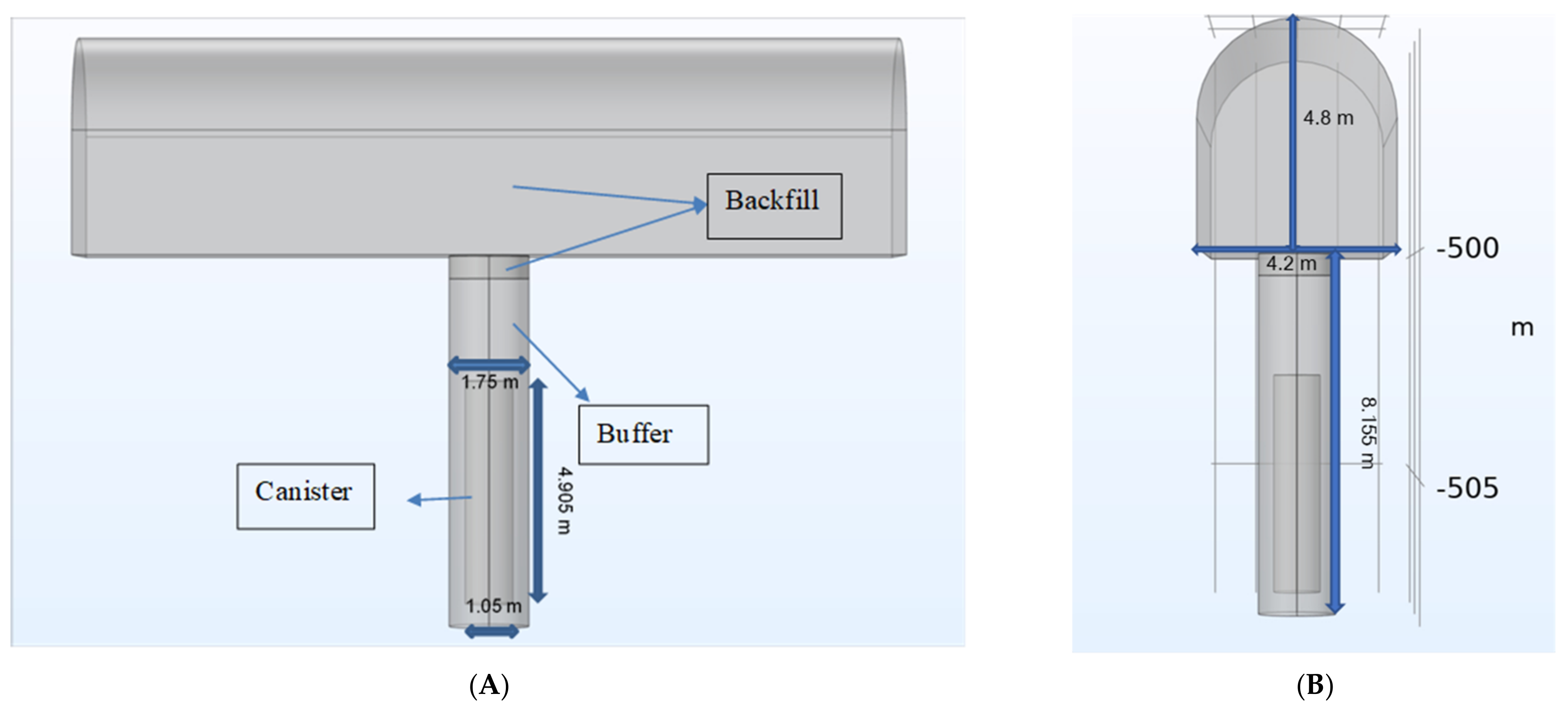
The EBS must produce a tightness for canisters. Obviously, the embedded clay must be used to protect canisters from mechanical impact and must be very taut and almost free of groundwater permeation. These are the primary objectives of the buffer zone, and preventing the migration of discharging radionuclides is a secondary objective. Therefore, the disposal system mainly requires that the buffer material should maintain its tightness and ductility and should not shear or bend the disposal container. Currently, based on the SKB concept, the disposal system’s buffer zone design has been proposed, which is called KBS-3 V [
6]. The design principle was introduced as early as the late 1970s. Later, other countries, such as Canada, South Korea, Finland, and Japan, also implemented it as the standard concept. Moreover, it possesses good characteristics that allow intermittent waste placement, providing enormous time for preparing deposition holes and placing buffers and containers [
6]. The manufacturing and placement of the buffers must ensure the high homogeneity and high density of mature clay for the ions to be transported by diffusion rather than flow, affording the standard that the minimum final density of the mature buffer zone should be 1950 Kg/m
3. However, literature indicates that the thermal-hydraulic-mechanical (THM) model, which is used to predict the soil mechanical properties of the buffer zone, states that the final density will be uneven, which has been verified by field tests. This is because internal friction prevents the initial, very significant density difference [
6,
7].
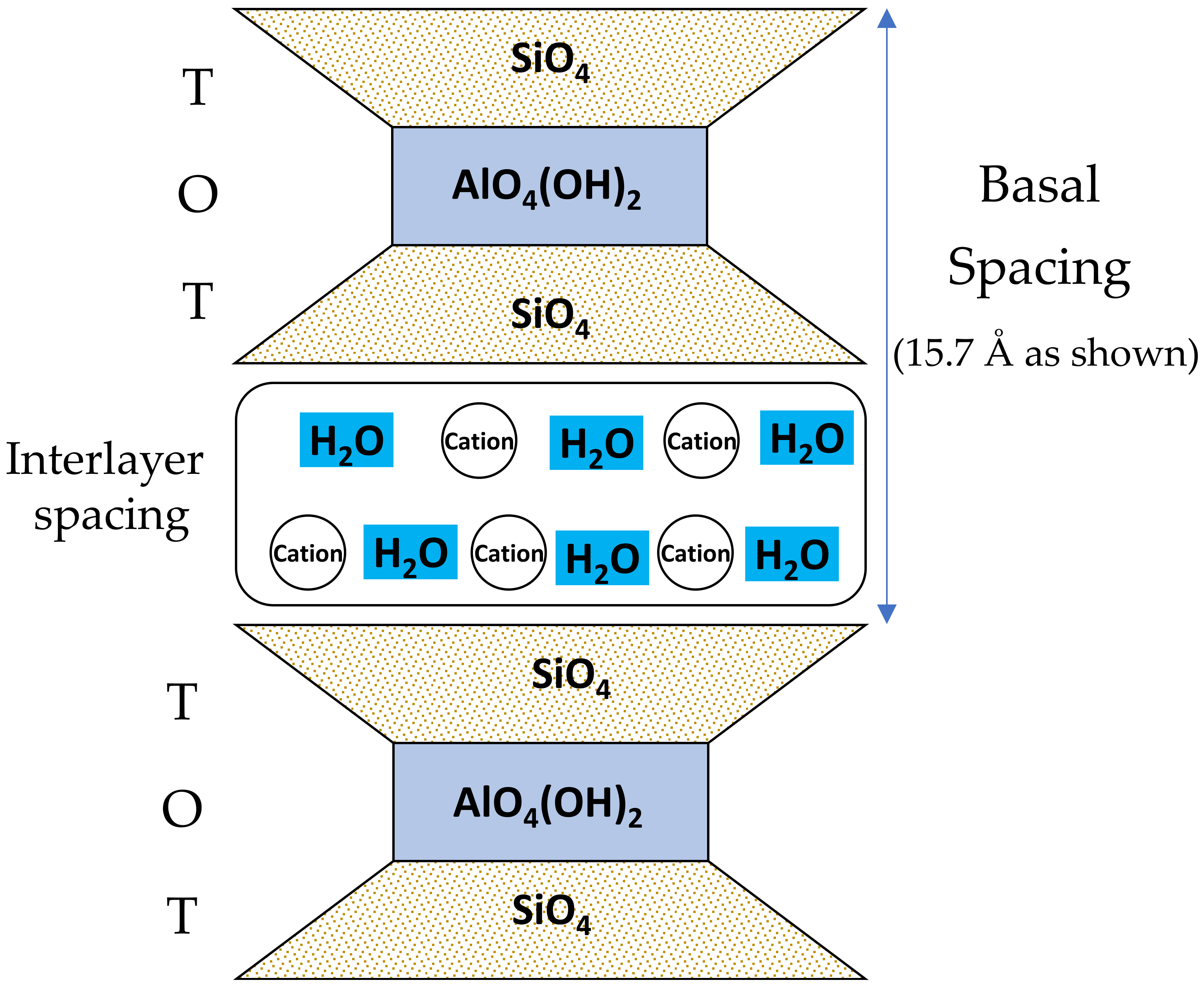
Bentonite is used as a buffer material in most high-level radioactive waste (HLW) repository designs. Smectite clay is the main mineral component of bentonite and plays a key role in controlling the buffer’s physical and chemical behaviors [
6,
8]. According to the concept of Sweden and several other concepts, a buffer zone comprising highly compacted smectite clay blocks is used as the main component. This denotes that these blocks will expand via hydration and combine with water from the host rock to close the gap between the block and host rock, which is required to place the block. A question that is often speculated upon: are the joints between the blocks used as paths for rapid water inflow, causing local expansion and irregular uplift and fracture of individual block? Clearly, dry cracks are formed in the hottest part of the buffer zone after a block’s hydration swelling. Another question is whether the density in the final maturation buffer is lower than the specified 1950 Kg/m
3. This risk can be minimized through careful material control, but risk still exists. In other words, water seeps into the waste canisters, which may cause high vapor pressure, causing the compression of the buffer material. Pusch [
6] indicated that these phenomena are the evolution and possible deterioration of the buffer materials in radioactive waste disposal facilities [
6].
To provide the necessary performance over a period of time, the buffer material is required to not undergo mineralogical change, desiccation, or cementation. Some countries (such as Sweden, Belgium, Spain, and France) intend to maintain the bentonite temperature below 100 °C. Other countries plan to allow higher temperatures. For example, the Swiss concept stipulates that the maximum temperature of bentonite should be less than 100–110 °C, but the maximum temperature near the canister is 150 °C. The smectite-rich clay with 40–60% water saturation exhibits low thermal conductivity, which decreases under the prevailing thermal gradient in the deposition hole. Some concepts intend to include materials with high thermal conductivity (such as graphite and silica sand) or wet buffer materials to increase the buffer material’s thermal conductivity [
6].
In the past decades, numerous research projects and studies have been conducted worldwide to understand the complex behavior of bentonite as a buffer material more widely and deeply, in geological radioactive waste disposal. A wide range of aspects related to the thermal–hydraulic–mechanical–chemical processes of bentonite have been studied, including high temperature influences on bentonite performance [
9,
10,
11,
12], groundwater/gas flow characteristics within bentonite [
13,
14,
15,
16,
17], swelling pressure and mechanical properties [
18,
19,
20,
21,
22,
23,
24,
25], and the mineral chemical evolution of bentonite [
26,
27,
28]. Moreover, experimental analysis and numerical simulation have been employed to study the performance evaluation of bentonite in the thermal–hydraulic–mechanical–chemical coupling process under environmental evolution conditions [
29,
30,
31]. However, previous studies often did not consider the porosity change caused by smectite dehydration in bentonite since decay heat influences the transport concentration of radionuclides in buffer materials when radionuclides are released from waste canisters.
The HLW repository concepts in Taiwan, the main thermal constraint placed on an EBS is that the bentonite buffer temperature should be less than 100 °C at the bentonite–canister interface. However, the long-term functions of buffer clay could be lost through smectite dehydration under the prevailing temperature and temperature gradient conditions that arise from waste decay heat. Therefore, the influence of higher waste decay temperatures on bentonite performance requires investigation. The chemical evolution of the bentonite buffer and bentonite degradation in the EBS of HLW disposal repositories caused by thermals affecting smectite dehydration are topics seldom discussed in the performance assessment of EBS. Therefore, in this study, we used the chemical kinetic model of smectite dehydration to calculate the interlayer water expelled from smectite that is caused by higher temperatures of waste decay heat, and study the porosity change of bentonite caused by smectite dehydration and evaluate the effect of porosity change on the transport of radionuclides through buffer materials.
3. Comparison of Analytical Solution and Numerical Simulation for Radionuclide Transport
This study analyzed the migration of key radionuclides affected by temperature in the engineering barrier and did not consider the migration of radionuclides in the geo-sphere or the dose assessment of radionuclides entering the biosphere. We used the analytical solution to verify the COMSOL model in the radionuclide transport simulation so we could confirm the performance of the model and the feasibility of the simulation results.
The governing equation for radionuclide transport can be expressed as follows:
where
Ri is the retardation factor,
D is desperation or the diffusion coefficient,
V is velocity,
λ is a decay constant,
Kd is the distribution coefficient,
ρ is the density, and
ε is the porosity.
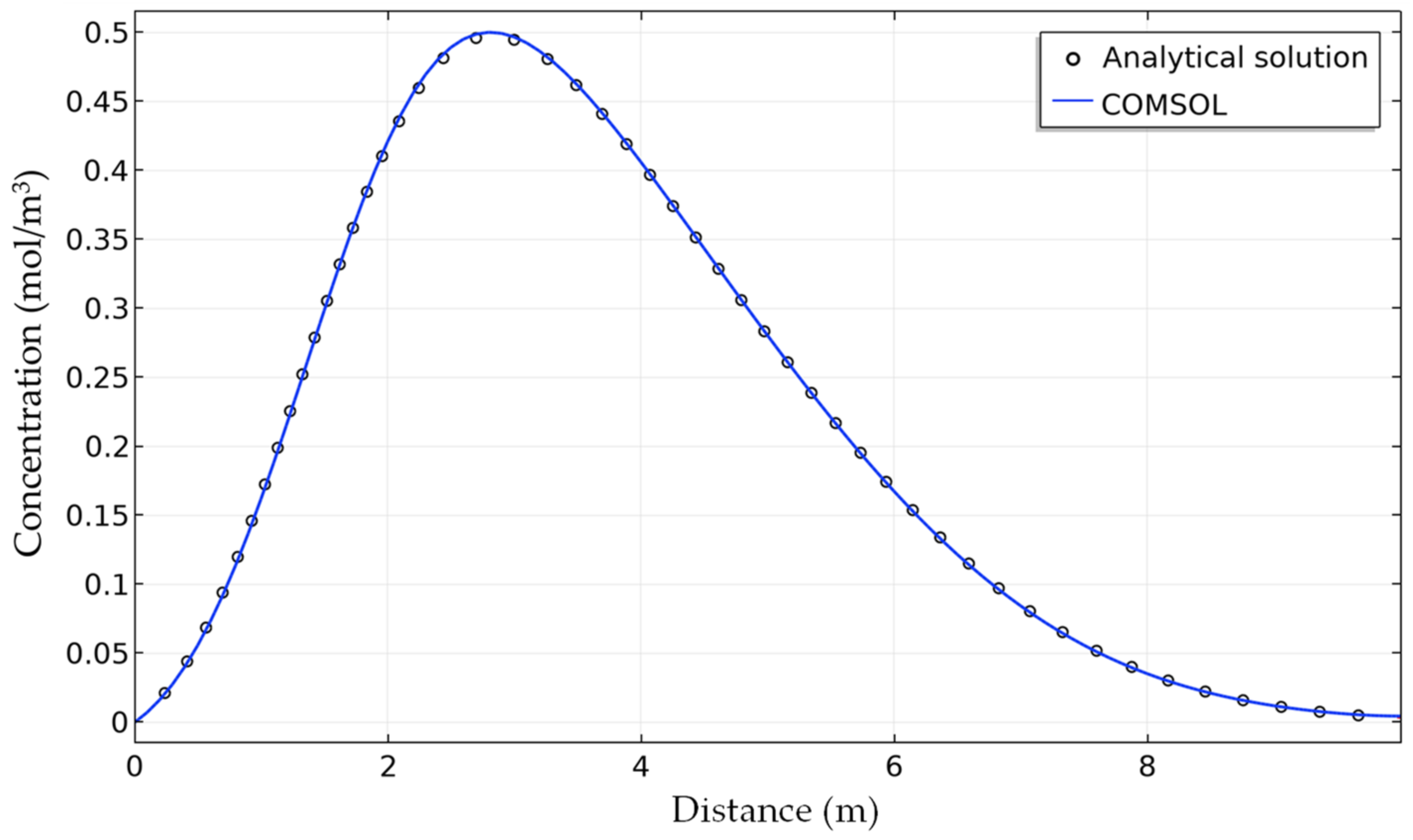
We used the analytical solution of three different tracer tests (conservative, decaying, and adsorption) [
45] to compare the simulation results of COMSOL in a one-dimensional transient transport. The model domain was set as 10 m and the water flow velocity was constant. At the inflow boundary (
x = 0), the concentrations of all three tracers were main-tained at 1 mol/m
3 at 0–15,000 s and 0 afterward.
Table 4 lists the model parameter values for the simulation of the tracer test. The COMSOL simulated concentration in the model domain was compared with the advection–dispersion analytical solution of the three dif-ferent tracer tests (conservative, decaying, and adsorption) at 20,000 s (see
Figure 5,
Figure 6 and
Figure 7).
Analytical solution of the transient-conservative tracer case is the following equation:
Analytical solution of the transient-decaying tracer case can be expressed as follows:
Analytical solution of the transient-adsorbing tracer case is presented in (22):
Through the analytical solution for numerical modeling validation of three test cases, we found that the simulation results of COMSOL 1D transport were very consistent with the analytical solution. Therefore, we can apply the COMSOL transport model to simulate and predict the decay and adsorption of radionuclides.
4. Effects of Porosity Change on the Radionuclides Transport through the Buffer Material
To prove how the effect of temperature on the porosity of bentonite significantly impacts the results of the safety assessment, we used a test case to prove this. Assuming that the canister will fail after the closure of the disposal repository, the failure time is divided into three periods: early, medium, and late. Early failure assumes that the canister will fail within 1–1000 years after closure, mid-term failure assumes that the canister will fail within 10–100,000 years after closure of the disposal facility [
46]. Herein, we present the early failure scenarios. The early failure case assumes that the failure time of the canister is one year after disposal repository closure.
Figure 8 shows the case where the simulation time is 20,000 years and the minimum transport distance and concentration penetration path between the fracture and the paths of the canister are called Q1, Q2, and Q3 where Q1 is the path at the vertical intersection of the canister and fracture, Q2 is the path at the Excavation Disturbed Zone (EDZ) under the disposal tunnel, and Q3 is the path at the junction of EDZ and the disposal tunnel top [
47].
This simulation only evaluated the radionuclides transport to Q1 in near-field. Then, the influence of porosity change on the transport processes in buffer material was also evaluated. We found that the effect of temperature change on the porosity is the most obvious near Q1. Radionuclides of I-129, Ni-59, Sr-90, and Cs-137 were selected for simulation analysis in early failure case. The model domain is 0.35 m.
The calculated saturated hydraulic conductivity for compacted bentonite is 1.9 × 10
−13 m/s based on the computation model [
48]. The experimental value of the hydraulic conductivity is 6.4 × 10
−14 m/s for the compacted FEBEX bentonite at dry density of 1650 kg/m
3 and is subject to granitic water [
49]. Thus, the hydraulic conductivity of the compacted bentonite is very low. Therefore, only the diffusion transport was considered in this study. For the radionuclide release model, the degradation rate (DR) and instant release coefficient (IRF) were considered [
46].
Table 5 lists the model parameters.
5. Results
This study adopted the chemical kinetic model of smectite dehydration to calculate the amount of water expelled from smectite clay minerals because of higher temperatures of waste decay heat. The results were as follows:
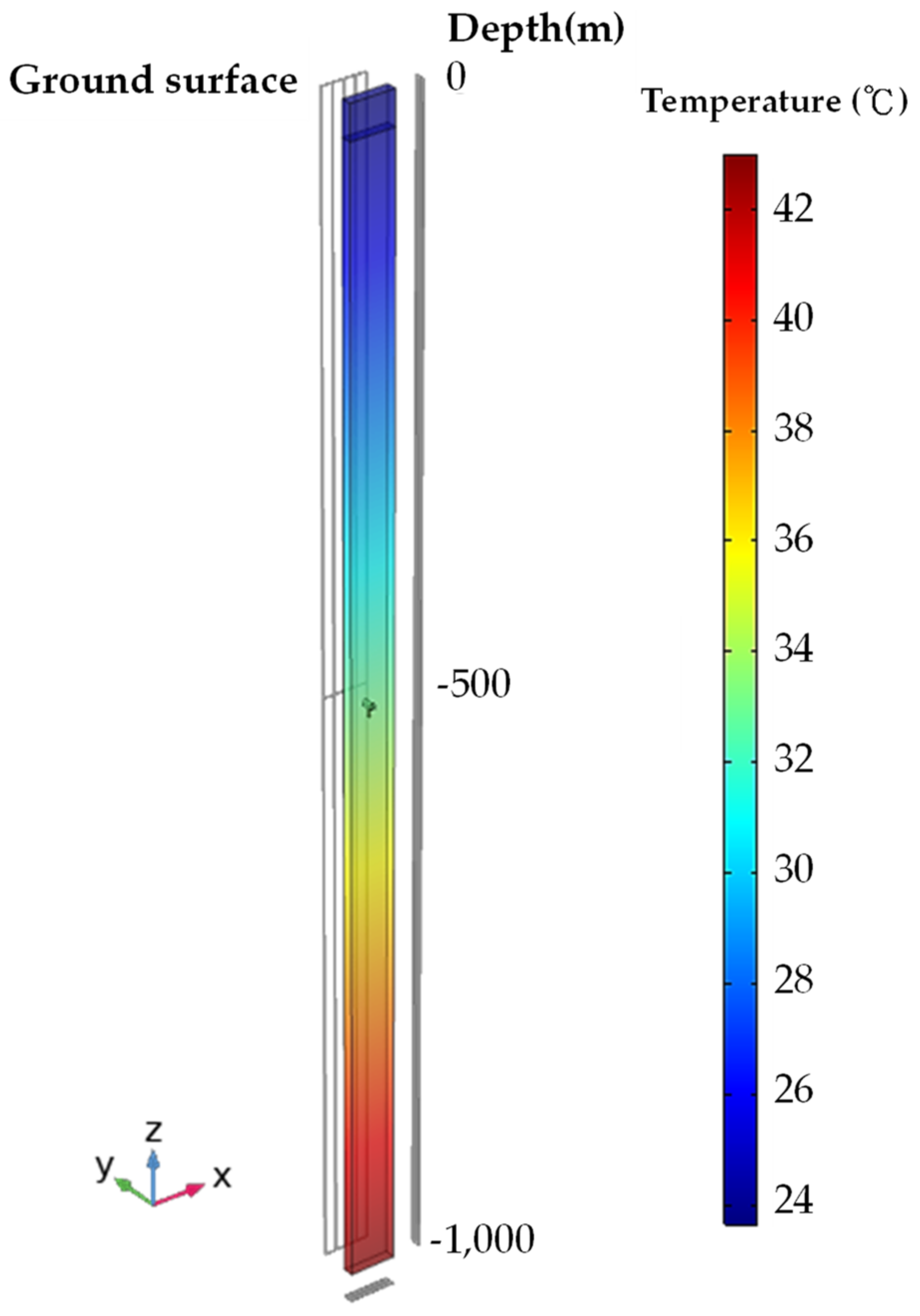
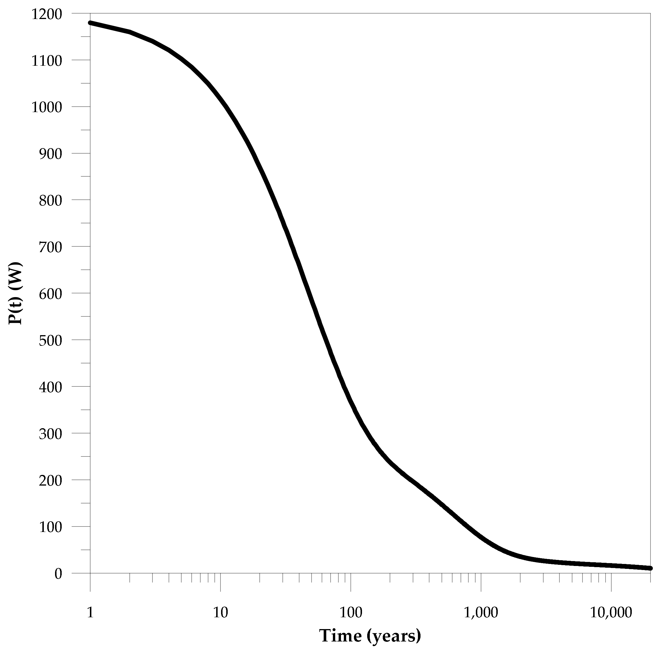
The heat-generating spent fuel was contained in the canister. The canister heat decay in less than 20,000 years was calculated using Equation (2) and initial canister power of 1200 W, as shown in
Figure 9. In the calculation, we used the COMSOL model to calculate heat transport through the EBS to the host rock during a 20,000-year period. The parameters for the heat transport simulation are tabulated in
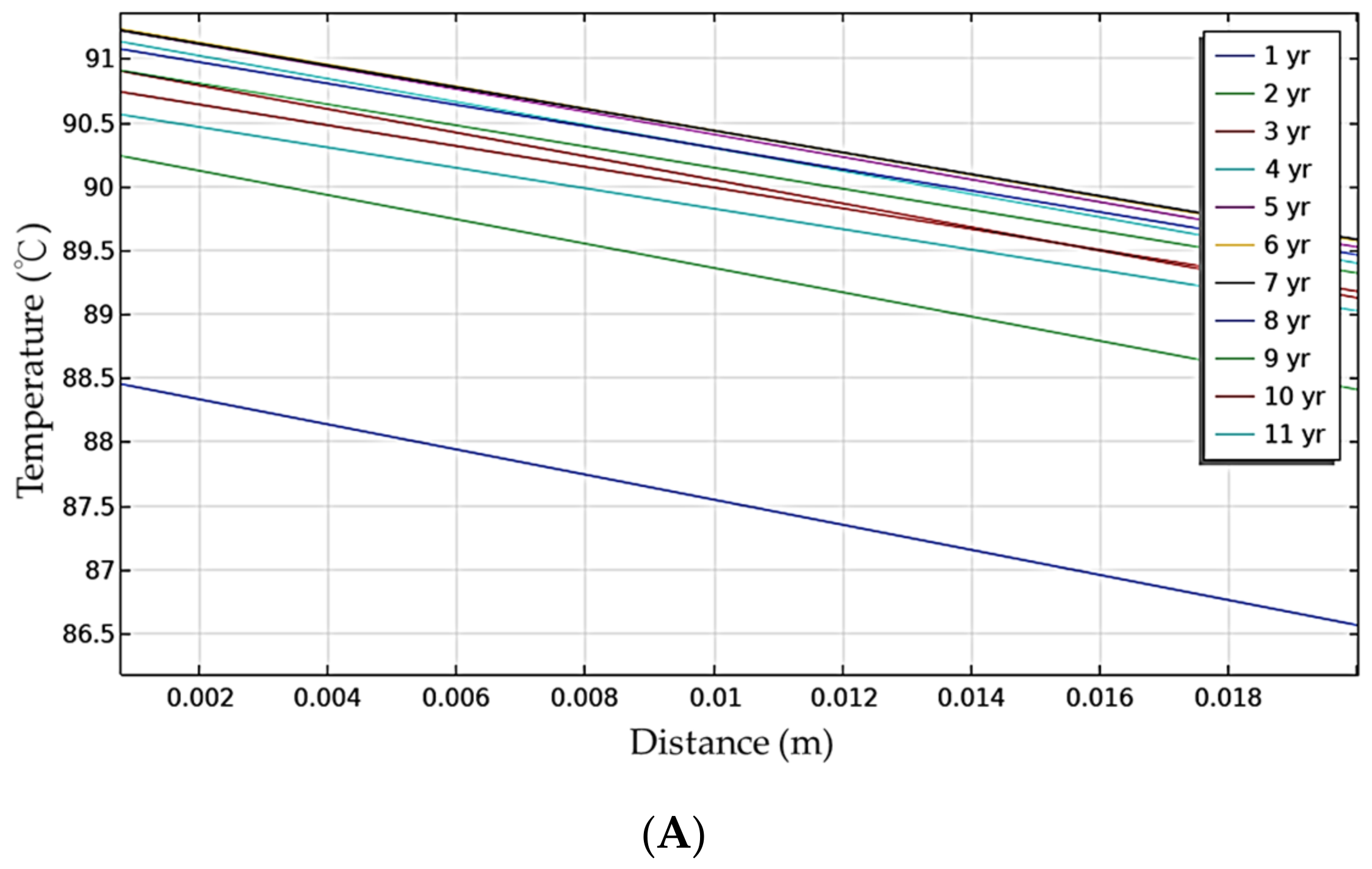
Table 2. The highest temperature of the buffer material occurred in the sixth year;
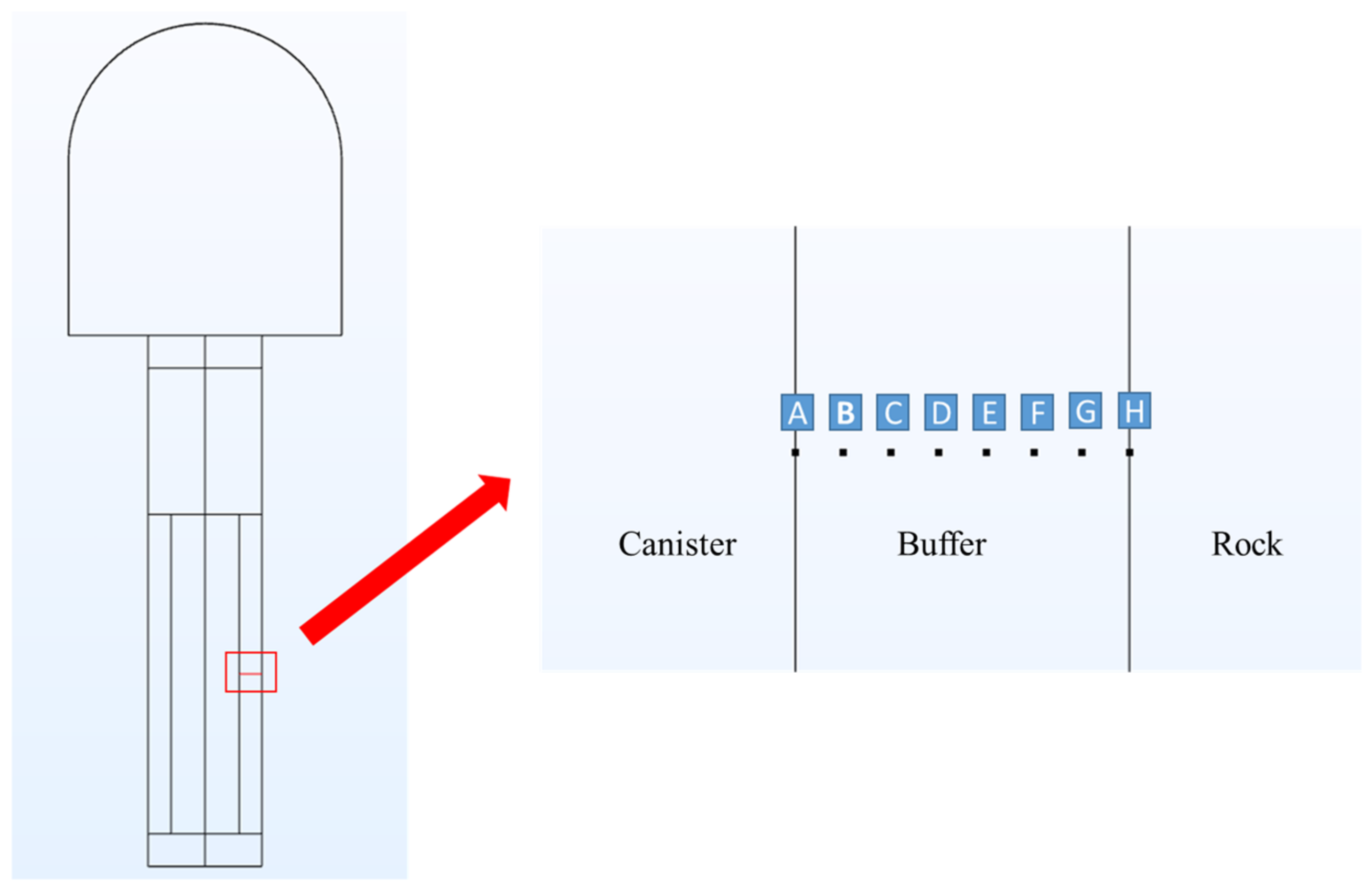
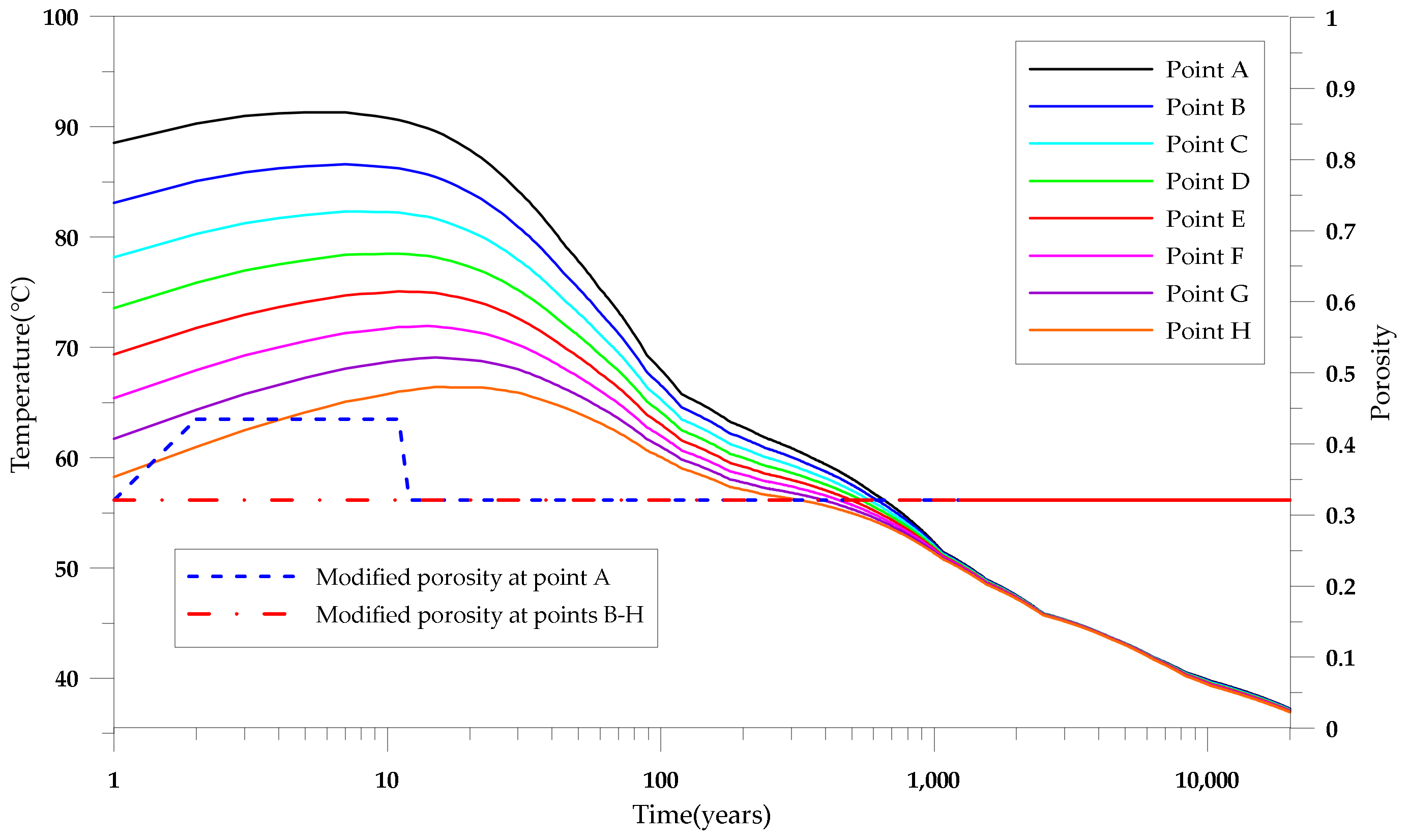
Figure 10 shows the temperature profile of that year. We selected eight points, A, B, C, D, E, F, G and H, with 5 cm between each, as the represented points for temperature calculation within the buffer (
Figure 11). The temperature distribution for the eight points during the 20,000-year-period is shown in
Figure 12.
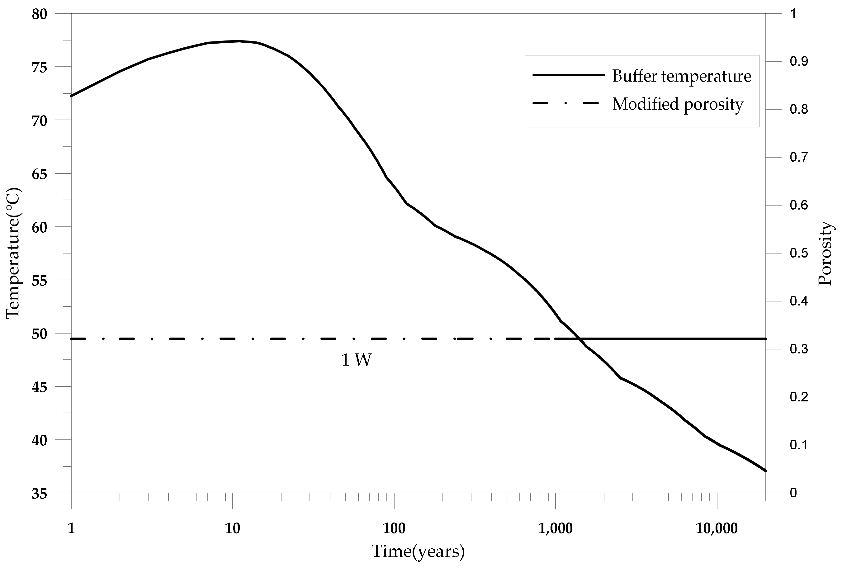
Figure 13 shows the average temperature evolution within the buffer material. Notably, the temperature peak occurs before 10 years. After approximately 20,000 years, the thermal caused by the release of the canister had dispersed and the temperature had reduced to nearly geothermal background level. The smectite dehydration times for 2W–1W and 1W–0W transitions are shown in
Table 6. Note worthily, the dehydration times were relatively fast with values of 3661 s (2W–1W) and 24,799 s (1W–0W) at 35 °C and 90 °C, respectively. The hydrous state porosity due to the temperature evolution was equal to 0.177 at 0 years and 0.321 at 1–20,000 years, as shown in
Figure 13.
Figure 14 shows the buffer zone of 0–0.01 m near the canister during the 3–10-year-period while the temperature exceeds 90 °C, which means that the porosity in this state is equal to 0.435 and the hydrous state of the smectite is 0 W. In the buffer zone of 0.01–0.35 m away from the canister, the porosity is equal to 0.321 (1–20,000 years) with a hydrous state of 1 W.
Table 7 shows the buffer volume and compression amount caused by dehydration and rehydration. In the 0 W state, the radial compression value is 2.485 cm. During the period of 10–20,000 years, the decay heat temperature will maintain the bentonite in the 1 W state and cause a 2.427-cm radial compression.
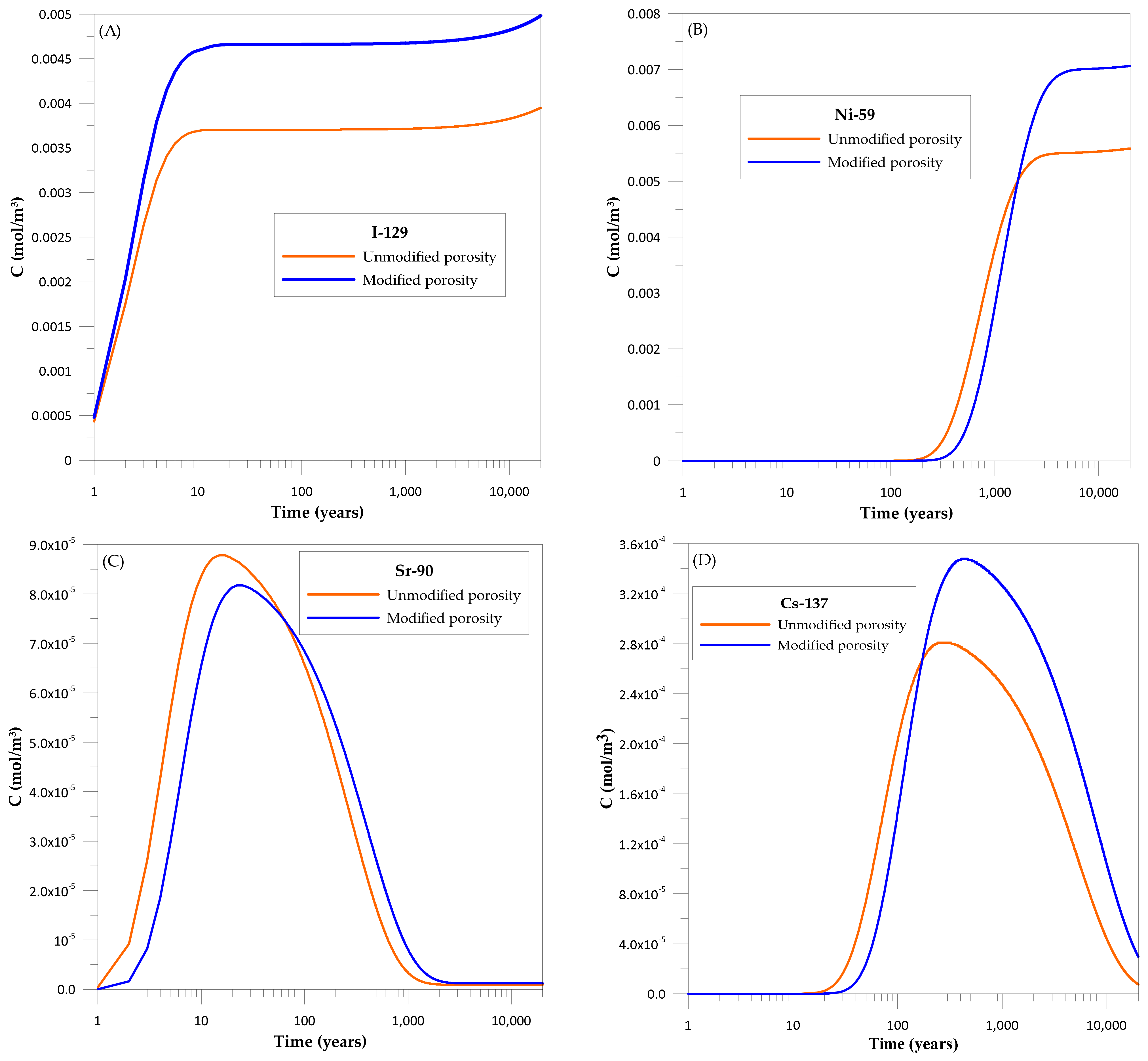
Temperature can cause smectite dehydration and promote porosity changes. To further understand the effect of porosity change caused by dehydration on radionuclide migration, we selected I-129, Ni-59, Sr-90 and Cs137 to compare the release concentration of radionuclides at point H in
Figure 11 through the buffer material with and without porosity correction. The literature suggests that the porosity of the buffer material is between 0.41 and 0.46. When the saturated density of the buffer material is 2000 kg/m
3, the porosity is 0.435 (i.e., the average value of 0.41–0.46) [
50]. Since the value of 0.435 is often used for porosity in safety evaluations, the unmodified porosity was also set to 0.435 in this study. Using the hydration state developed in this study to select the modified porosity, we found that it is affected by decay heat in the region of 0–0.01 M, so the temperature will be greater than 90 °C in 3–10 years, and the porosity is 0.435 in 3–10 years. Other time periods are shown in
Figure 14, and the porosity of 0.321 is seen in both time periods of 1–2 years and 11–20,000 years. At the region of 0.01–0.35 m, the porosity is 0.321 between 1 and 20,000 years.
Figure 15 shows the concentration breakthrough curves with and without porosity correction of I-129, Ni-59, Sr-90 and Cs137, respectively. We found that the simulated radionuclide release concentration with modified porosity was greater than the simulation result using the traditional porosity value of 0.435. The results showed that the safety assessment and analysis of radionuclide migration using unmodified porosity may underestimate the concentration of radionuclides released from EBS. This study also showed that the porosity correction model may be an approach to the real situation of radionuclide release concentration.
7. Conclusions
This study adopted the kinetic dehydration of interlayer water and the hydration state of the interlayer to calculate the amount of water expelled from smectite clay minerals caused by higher temperatures of waste decay heat. The temperature peak of about 91.3 °C occurred at the junction of the canister and buffer material in the sixth year. After approximately 20,000 years, the thermal caused by the release of the canister had dispersed and the temperature had reduced close to geothermal background level. The modified porosity of bentonite due to the temperature evolution in buffer zone between 0 and 0.01 m near the canister was 0.321 (1–2 years), 0.435 (3–10 years), and 0.321 (11–20,000 years). In the 0.01–0.35-m buffer zone, the porosity is equal to 0.321 (1–20,000 years) with a hydrous state of 1 W. We demonstrated radionuclides transport through the buffer material under the change of bentonite porosity caused by decay heat. I-129, Ni-59, Sr-90 and Cs137 were selected to observe how the porosity evolution influences radionuclides with and without retardation. We also found that the concentration of radionuclides released from the buffer material was higher than that using the unmodified porosity value of 0.435. It occurs after 1, 1671, 63, and 172 years for the I-129, Ni-59, Sr-90, and Cs137 radionuclides, respectively. The results showed that the safety assessment and safety case analysis of radionuclide migration using unmodified porosity may underestimate the radionuclide concentration released by EBS. Therefore, the porosity correction model proposed in this study proves to be an effective approach to the real situation of radionuclide release concentration.
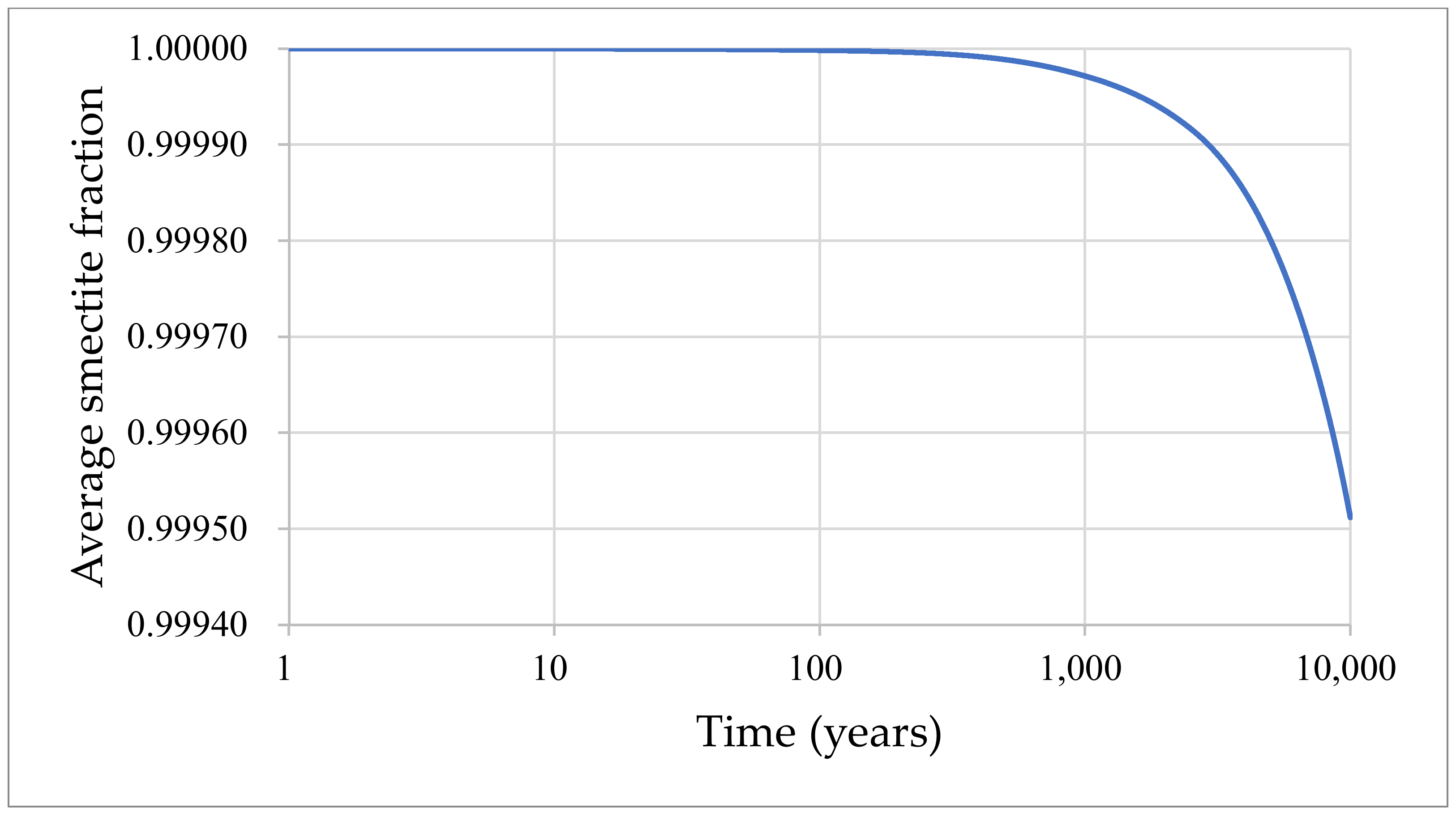
Smectite clay could cause volume shrinkage because of interlayer water loss in smectite and lead to bentonite buffer compression. Further investigation of the swelling pressure of smectite and the confining stress of the surrounding host rock could provide further insights into the computation of bentonite consolidation and compression as well as smectite volume expansion. Less than 0.05% of smectite is transformed to illite in 10,000 years. A decay heat temperature of below 100 °C within the buffer material is a very significant design condition for the EBS of radioactive waste disposal. The results may be used in advanced research on the evolution of bentonite degradation for performance assessments and safety analyses of the final disposal of HLW.


