1. Introduction
Nuclear energy plays a key role in the development of clean energy and reduction of carbon emissions all over the world. The accelerator driven subcritical system (ADS) is a new nuclear energy system which could not only produce clean energy but also incinerate actinide nuclides and long-lived radioactive fission products [
1]. The ADS device consists of a subcritical core, a high-energy proton accelerator and a neutron spallation target, in which the fission process is sustained by a spallation neutron source. Compared with critical nuclear energy systems (CNESs), ADSs have a better performance concerning nuclear waste transmutation due to a harder neutron spectrum. In recent years, ADS has been attracting more and more attention because of its superior neutronics and safety characteristics [
2]. Conceptual designs of three types of experimental accelerator driven systems (XADSs) have been studied by the European Atomic Energy Community within its fifth framework program [
3], which includes a zero-power subcritical facility YALINA, an 80 MW lead bismuth eutectic (LBE) cooled XADS, and a 50 MW multi-purpose hybrid research reactor MYRRHA for high-tech applications. A roadmap for developing Accelerator Transmutation of Waste (ATW) technology was presented by the United States Department of Energy (DOE) [
4]; several researchers studied the physics design for using sodium or LBE as coolant of the ATW systems [
5,
6]. The Japan Atomic Energy Agency (JAEA) has investigated an 800 MW LBE-cooled subcritical reactor with a 1.5 GeV proton accelerator to transmute minor actinides [
7]. Research on a hybrid power extraction reactor (HYPER) was carried out by the Korea Atomic Energy Research Institute (KAERI) to produce energy and transmute nuclear waste [
8]. The China lead-based reactor (CLEAR) and the Chinese initiative accelerator driven subcritical system (CiADS) have been proposed by the Chinese Academy of Sciences for the transmutation of nuclear waste and sustainability of nuclear energy development [
9,
10]. The conceptual design of a 10 MW LBE-cooled CLEAR has been completed, and a proton accelerator with 650 MHz multicell superconducting radio frequency (SRF) in the CiADS device and an accelerator-driven advanced nuclear energy system (ADANES) have been proposed [
11].
The component of the ADS system and its operation principle are significantly different from those of the CNES system. To ensure safe operation and optimize reactor design of the ADS system, it is necessary to investigate its transient characteristics under accident conditions and analyze its advantages and disadvantages compared to the CNES system. Several codes have been developed for safety analysis of ADS by using a neutronics model coupled with thermal and hydraulic feedback effects [
12]. Reference Chen et al. [
13] analyzed some safety characteristics for a lead-bismuth eutectic (LBE) cooled ADS using the extended SIMMER-III code. In addition, Suzuki et al. [
14] investigeted the unprotected blockage in a single fuel assembly and severe core-melt accidents with the updated SIMMER-III. The neutronics and thermal-hydraulics coupled simulation program was developed by the FDS team for the design and research of lead or LBE cooled ADS reactors [
15], and three typical transient accidents were simulated with NTC code, such as beam trip and transient overpower condition [
16]. Reference Lu et al. [
17] used the RELAP5 program for a safety analysis on loss of flow accidents and external source transients of an 800 MW ADS with the code modifications of the point-kinetics model and the thermal property package. These studies are mainly focused on the transient characteristics of ADS itself, but did not analyze the differences of inherent safety features between ADS and CNES. Reference Schikorr [
18] has built a lumped parameter model of the neutronics and thermal-hydraulics to demostrate the differences of dynamic behavior between ADS and critical fast reactor. The transient calculations of critical and subcritical LBE-cooled reactors were carried out by using the FAST code [
19], including the dynamic behaviors of overpower, loss of flow and loss of coolant accidents. Reference Wang et al. [
20] simulated the loss of heat sink accident for both ADS and the critical reactor by NTC code, in which the amplitude equations of core neutronics are the point-kinetics model. However, the point-kinetics method may be inaccurate in the case of severe source perturbations involving strong reactivity feedback that produce great flux distortion, which may happen during a serious accident [
21,
22]. Therefore, the variation of the spatial shape function with time should be considered in the ADS model. In this work, a space–time neutron diffusion model of the ADS reactor is developed to replace the point-kinetics neutron model to meet the requirement of satisfactory accuracy for transient safety analysis. The differential equations of neutron diffusion are calculated by the spatial discretization with the finite difference method and the time discretization with a backward differentiation formula (BDF) method [
23,
24]. In addition, the space distribution of the spallation neutron source in the diffusion model is calculated by the Monte Carlo method. The safety characteristics of ADS are analyzed under typical accident conditions and its advantages and disadvantages are compared to the CNES system.
The objective of this research is to analyze differences of the safety characteristics of the LBE-cooled ADS and CNES by using a neutronics and thermal-hydraulics coupled simulation code named ARTAP. The developed code consists of a space–time neutron diffusion equation with a spallation neutron source model and a thermal-hydraulics model with a package of thermophysical properties, which could be used for calculations of both the LBE-cooled ADS and the LBE-cooled CNES. Three typical accidents are calculated by ARTAP code, including reactivity insertion, loss of flow, and loss of heat sink. In addition, the accident simulations are not only performed in the case of unprotected transient, but also in the case of protected transient, i.e., transient with interruption of accelerator beam for ADS and with insertion of shutdown rod for CNES. The transient behavior of the reactor power and the temperatures of the fuel, cladding, and coolant are investigated during the accident sequences.
2. Calculation Model and Method
In this work, the Italian 80 MW LBE-cooled reactor is chosen as the research object to study differences of the safety characteristics of the ADS and CNES [
19]. On the one hand, we adopt this reactor because it is sufficiently representative for the various ADS conceptual designs [
25]. On the other hand, compared with other ADS conceptual types we can obtain the detailed composition and geometric distribution of all materials (fuel, cladding, coolant, spallation target, reflector, control rod, etc.) for this reactor through the existing literature and technical reports. After obtaining these basic data and empirical correlation, the calculation of spallation neutron distribution between the accelerator proton beam and the metal target, the processing of macroscopic cross sections in the reactor core, and the use of material thermophysical properties for the thermal-hydraulics analysis could be carried out during the reactor modeling process.
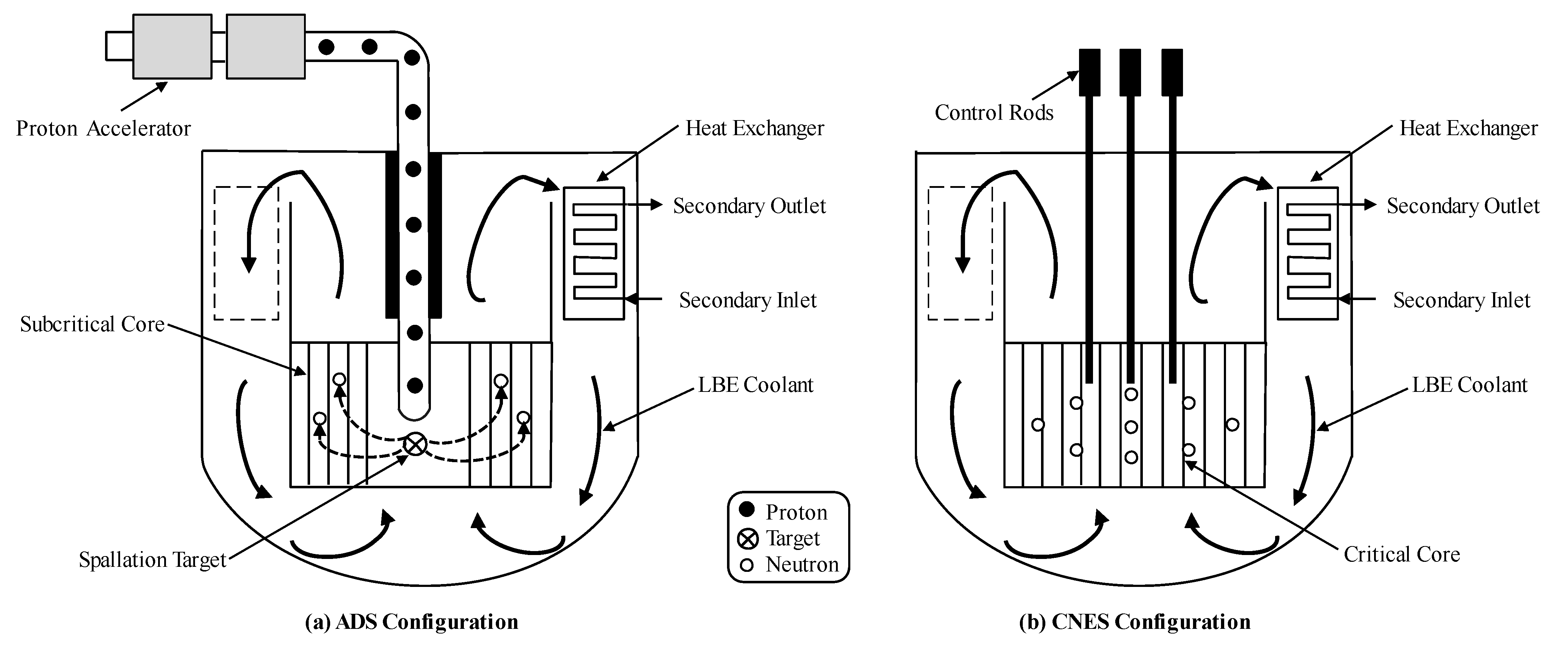
The ADS device consists of a subcritical core, a high-energy proton accelerator and a heavy metal spallation target. The CNES reactor is a critical core; its operational process is implemented by the control rods. The configuration of the LBE-cooled ADS and CENS is shown in
Figure 1. It can be seen from
Figure 1a that the accelerator proton beam is introduced into the target and then hits the metal target to initiate the spallation reaction. As a result of the spallation reaction process, neutrons will be supplied to the subcritical reactor core, which serves as an external neutron source to maintain fission chain reactions. On the one hand, the power level could be changed by adjusting the beam intensity during the transient operating conditions. On the other hand, the external neutron source in the core could be interrupted by quickly cutting off the accelerator beam so as to achieve emergency shutdown protection under accident conditions. The heat produced in the core will be carried out by the coolant of lead bismuth eutectic (LBE). In the heat exchanger (IHX), the coolant of the primary side is high temperature LBE, and the coolant of the secondary side is an organic diathermic fluid. As shown in
Figure 1b, the CNES core itself could sustain a chain fission reaction without external neutron source, and the power level could be adjusted by the control rods during the transient process. The secondary circuit of CNES is similar to that of ADS.
2.1. Process of Numerical Calculation
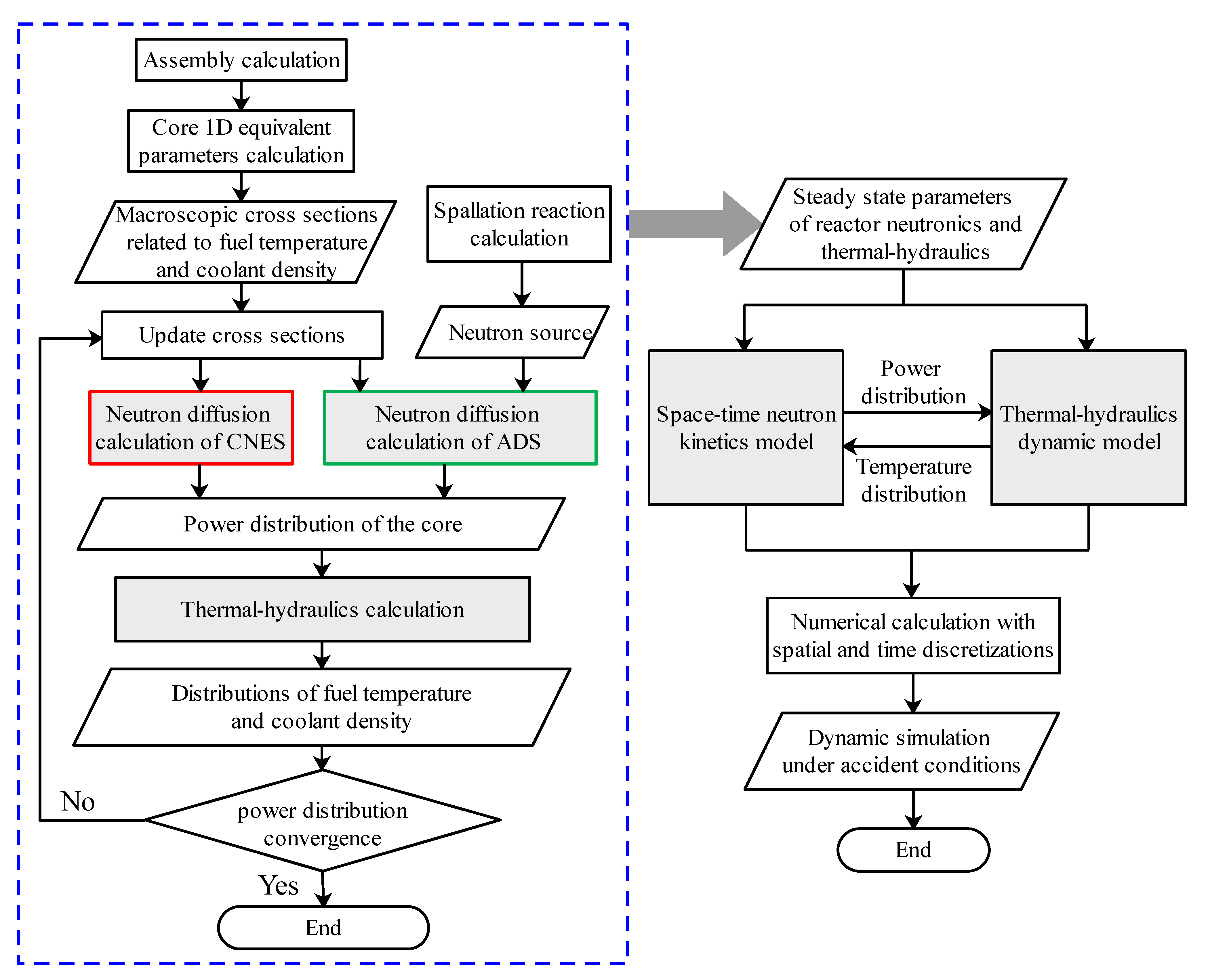
In this paper, a developed ARTAP code is applied in comparative analysis of the safety characteristics between the LBE-cooled ADS and CNES, which is comprised of a steady-state analysis module and a transient analysis module. The steady-state analysis module couples a one-dimensional neutron diffusion equation and a thermal-hydraulics single-channel model [
26]. The single channel model includes the heat conduction in the fuel element and the heat transfer from cladding to coolant. A flowchart of the neutronics and thermal-hydraulics coupled calculation is shown in
Figure 2.
Before the assembly calculation starts, the geometric arrangement and detailed composition of all materials (fuel, cladding, coolant, spallation target, reflector, control rod, etc.) for the ADS and CNES reactors need to be determined through the existing literature and technical reports. After obtaining these basic data and empirical correlation, the calculation of neutron source distribution in the ADS spallation target, the processing of macroscopic cross sections for the subcritical core of ADS and the critical core of CNES, and material thermophysical properties introduced into the thermal-hydraulics model of both reactors could be carried out during the process of simulation calculation and comparative analysis, as shown in
Figure 2. When macroscopic cross sections and spallation neutron source are obtained, steady-state neutron diffusion equations of these two reactors could be solved, respectively, by the power iteration method. According to the power distribution by the neutronics calculation, the thermal-hydraulics analysis is performed for both reactors, and the obtained distributions of fuel temperature and coolant density are selected as the feedback parameters to update their nuclear cross sections. Then the neutron diffusion calculations are carried out for both reactors, respectively, to update the power distributions again. This coupling iterative process continues until some criterion for convergence is met. The steady-state parameters of reactor neutronics and thermal-hydraulics are provided as initial parameters for dynamic simulation. The numerical calculation of dynamic models is divided into two steps, i.e., the spatial discretization with the finite difference method and the numerical solution of nonlinear time-dependent differential equations with a backward differentiation formula (BDF) method [
23].
2.2. Space–Time Neutron Diffusion Model
While the three-dimensional full core multi-physics modeling of nuclear reactor is an effective way to obtain the key information of the reactor core with high precision, the required data storage space is very huge and the running time is quite long. In a few special calculations like performing the reactor control system design, transient safety analysis or load following study, the detailed radial information of the reactor core is not necessarily needed due to the radially symmetrical layout of fuel assemblies and control rod banks [
27]. Thus, a one-dimensional neutron diffusion model in the axial direction will be more preferable when the calculation precision is not reduced.
2.2.1. Space-Time Neutron Kinetics Model
The space and time dependent neutron kinetics model of the ADS reactor is as follows:
where
is the average speed of neutrons,
is the neutron flux,
z is the axial position,
t is the time,
D is the diffusion coefficient,
and
are the macroscopic cross section of absorption and fission, respectively,
is neutrons yield per fission,
S is the spallation neutron source,
is the total delayed neutron fraction,
is the delayed neutron fraction of group
j, and
and
are the delayed neutron precursor concentration and decay constant, respectively.
For the CNES reactor, the Equation (
1) can be modified as:
The difference between Equations (
1) and (
3) is not only the absence of the source term in the critical core, but also the values of the cross-section parameters in Equations (
1) and (
3), which could be determined according to the composition and geometric distribution of all materials in the ADS and CNES cores. In the process of the neutron flux calculation, the finite difference method will be used for the discretization in space. This discretization is shown in
Figure 3, and the size of each node is
. The power iteration method is used to calculate the steady-state diffusion equation [
28], and the corresponding distribution of neutron flux could be determined by this iterative scheme. After the spatial discretization, neutron kinetics models could be transformed into the normal forms of time-dependent differential equations which could be solved by a backward differentiation formula (BDF) method with a scheme of implicit time discretization.
2.2.2. Spallation Neutron Source Calculation
The space and energy distributions of the spallation neutrons
in the target for the ADS reactor are calculated by the Monte Carlo transport code, which could simulate the interaction between an accelerator proton beam and a metal target [
29]. The beam footprint at the target is circular with a diameter of 0.16 m, and its height is 0.9 m. According to the geometric arrangement and material composition of the spallation target, a three-dimensional model of the target was built using the Monte Carlo code and the neutrons tracked in the spallation target were tallied into an output file, then the distribution of spallation neutrons could be obtained, which are used asa shape function of the spallation source during the process of ADS neutron diffusion calculation. The distributions of spallation neutrons along the axial direction of the core and its energy spectrum are shown in
Figure 4.
In the process of transient simulation, the space and time-dependent spallation source term
in the neutron diffusion is factorized into two functions; the shape function
is shown in
Figure 4a and amplitude function
of the spallation neutron source could be calculated by:
where
is the number of spallation neutrons released per proton,
e is the electron charge,
is the intensity of the proton beam that can be derived by the following formula [
30]:
where
is the total thermal power of the subcritical core,
is the averaged energy released per fission,
is the effective multiplication factor, which is an important concept in reactor physics. When neutron disappearance does not equal neutron regeneration,
is introduced to the steady state diffusion equation for criticality calculation, and the subcriticality
could be obtained, which means the distance from a criticality. After an external source is added into the subcritical core, the neutron population is perfectly balanced; thus,
should be eliminated in the ADS steady state calculation.
2.2.3. Macroscopic Cross Section Generation
Taking into account the Doppler effect and the coolant feedback effect, the parameters of macroscopic cross sections (
D,
and
) are mainly related to fuel temperature
and coolant density
in Equation (
1). The calculation of macroscopic cross sections is performed using a lattice physics code at different temperature points [
26]. Then the values of these parameters
,
and
could be obtained by a linear interpolation method. Finally, the one-dimensional equivalent parameters are obtained from flux volume weighting in three-dimensional space:
where
is the average value of the macroscopic cross-section (
D,
and
) in axial node
i,
is the position vector in three-dimensional space,
is the volume of axial node
i.
2.3. Thermal-Hydraulics Model
During the normal operation of the reactor, the fission energy produced by the nuclear fuel is transferred from the fuel pellet to the cladding, and then transferred from the cladding to the coolant. In this work, a single channel model is performed for the thermal-hydraulics calculation, which includes the heat conduction in fuel element and the heat transfer from cladding to coolant.
2.3.1. Heat Conduction in Fuel Elements
In order to obtain the spatial distribution of temperatures of fuel and cladding, the fuel element is divided into K nodes in the axial direction and L nodes in the radial direction, as shown in
Figure 5. Since the thickness and thermal resistance of cladding are much smaller than those of the fuel pellet, the cladding is only divided into three nodes in the radial direction to obtain its inner surface and outer surface temperatures. Axial heat conduction is ignored because of prevailing radius to length ratios and axial symmetry [
31]. Therefore, the heat conduction equation for the fuel pellet in the axial node
i could be written as:
where
and
denote the density and specific heat of the fuel pellet in the axial node
i, respectively,
and
denote the temperature and heat conductivity of the fuel pellet in the axial node
i, respectively,
is the volumetric heat rate.
Ignoring the heat generated in the cladding, we obtain the heat conduction equation for the cladding in the axial node
i as:
where
and
denote the density and specific heat of the cladding in the axial node
i, respectively,
and
denote the temperature and heat conductivity of the cladding.
2.3.2. Heat Transfer to Coolant
The heat transfer from cladding to coolant in the
ith node along the reactor axis direction can be described by the basic mass and energy conservation equations as:
where
,
,
and
denote the density, volume, specific heat and temperature of coolant in the axial node
i, respectively,
denotes the heat transfer coefficient between cladding and coolant,
is the heat transfer area between cladding and coolant,
denote the mass flow rate of coolant, and
and
denote coolant inlet and outlet temperatures, respectively.
In the design of fast spectrum reactors, heavy liquid metals such as lead or LBE are usually adopted as the coolant materials for high heat transfer coefficient and large heat capacity. The fuel assembly in the core is usually composed of triangular rod bundles, and thus the Ushakov correlation is used to analyze the heat transfer correlation between the heavy liquid metal coolant and the cladding [
32]. The heat transfer coefficient between cladding and coolant is calculated by:
where
is the heat conductivity of the coolant,
is the hydraulic equivalent diameter; the Nusselt number
in the rod bundles is as follows:
where
is the ratio of the pitch of fuel pins to its diameter,
is the Peclet number. It is valid for
, and
.
The package of thermophysical properties of materials was developed to insert into the thermal hydraulic model based on the experimental data and empirical correlation [
33,
34]. The correlations of the thermophysical properties of coolant, cladding, and fuel are presented in
Table 1.
2.3.3. Heat Exchanger Model
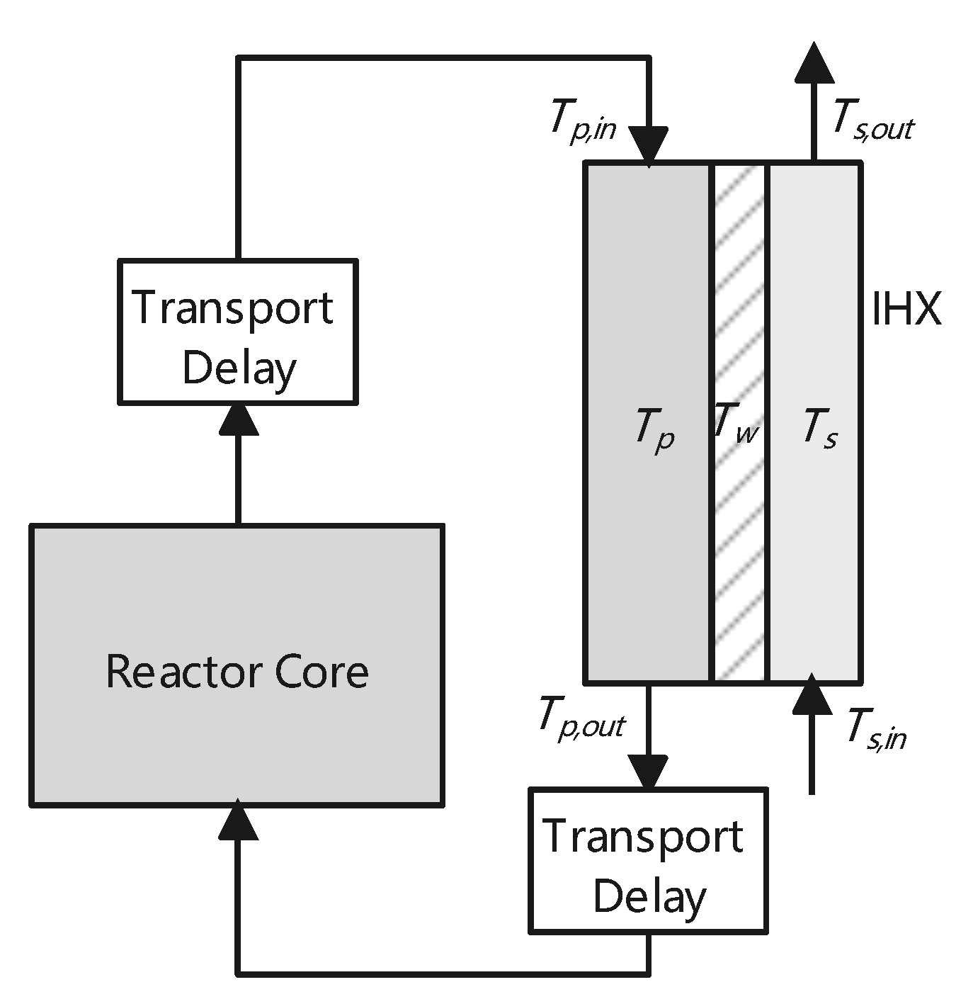
The primary coolant flows out of the core and enters the heat exchanger through the ascending channel. The primary coolant then flows down to the lower plenum after its heat is transferred to the organic diathermic fluid on the secondary side. The schematic diagram of the primary circuit is shown in
Figure 6.
The heat transfer models of primary coolant, tube wall and secondary coolant are as follows:
where
is the heat transfer coefficient between primary coolant and tube wall,
denotes the heat transfer coefficient between tube wall and secondary coolant.
The ARTAP code has been verified by comparing its predictions for both steady-state and transient cases of the OECD/NEA benchmark [
12]. The benchmark summarizes a comparative analysis of ten different codes. Three cited codes for the comparison are: TRAC-MOD, SAS4ADS and EXCURS-M, as they represent the range of data scatter in the published results of the benchmark report. The results indicate that ARTAP is accurate and efficient when applied for the safety analysis of the LBE-cooled ADS and CNES [
26].
3. Results and Discussions
The Italian 80 MW LBE-cooled reactor was chosen as the LBE-cooled ADS or equivalent critical system to investigate the safety characteristics in this work. The arrangement of assemblies and horizontal view of one-sixth of the ADS core and the CNES core are shown in
Figure 7. The ADS core is divided into several regions, as shown in
Figure 7a. The inner region consists of 120 hexagonal fuel assemblies, and the dummy assemblies in the outer region mainly contain LBE which is taken as the reflector. The central channel is designed to introduce proton beam into the spallation neutron target. The outside of the core region is filled with LBE coolant, which serves as axial reflector and radial reflector. The CNES core has a similar configuration without the spallation target, as shown in
Figure 7b, in which 19 additional fuel assemblies are added in the central channel to bring the reactor to critical state without external neutron source. In both the ADS and CNES systems, each fuel assembly includes 90 triangle-distributed fuel rods made of MOX pellet (PuO
/UO
with 23% Pu) in a stainless steel cladding. The main technical design parameters of these two reactors are listed in
Table 2. Three typical accidents are carried out to study the difference of transient behaviors between ADS and CNES, which include reactivity insertion, loss of flow, and loss of heat sink.
3.1. Reactivity Insertion Accident
During the operation of nuclear reactors, due to the failure of mechanical devices or the misoperation of personnel, the control rods are accidentally ejected and then positive reactivity is introduced, causing the reactor power to deviate from normal operating conditions. The introduction of instantaneous positive reactivity may lead to a sharp increase in the temperatures of the fuel pellet and the cladding, and even a rupture in the fuel element. In this paper, the reactivity insertion is realized by the control rod, and the approach is to adjust the absorption cross-section
of the control rod in Equations (
1) and (
3), where
z is the insertion depth of the control rod. Reactivity insertion accidents of 700 pcm (about 2
$) for ADS and CNES are simulated, and the comparative safety analysis of these two reactors is carried out. In addition, the accident simulation is not only performed in the case of unprotected transient, but also in the case of protected transient, i.e., transient with interruption of accelerator beam for ADS and with insertion of shutdown rod for CNES. The transient behaviors of the reactor power and the temperatures of the fuel, cladding, and coolant are investigated during the accident sequences.
3.1.1. Unprotected Reactivity Insertion
The Transient responses of ADS and CNES for unprotected reactivity insertion of 700 pcm are shown in
Figure 8. It can be seen from
Figure 8a that the ADS power only increases by about 25% after 700 pcm reactivity is introduced into the core, and then the power decreases slightly due to the negative reactivity introduced by the Doppler feedback effect and the coolant temperature feedback effect, and finally reaches a new equilibrium value. Meanwhile, the temperatures of the fuel center, cladding surface, and coolant outlet also ascend with the power increase and then gradually stabilize to a new equilibrium point. This is principally because the ADS reactor is a subcritical core driven by an external neutron source, in which the
is far from the critical point and the neutron multiplication capacity is weak after the core is inserted positive reactivity. Therefore, the power only rises to 1.25 times the steady-state value, and the maximum temperatures of fuel pellet and cladding are far below the safety limit under the unprotected reactivity insertion accident. The results show that the ADS has good inherent safety in the event of reactivity insertion accident, and its margin of criticality safety is large.
The simulation results also show that the the CNES power rose sharply to nearly 22 times the steady-state value under unprotected reactivity insertion accident. At the same time, the negative feedback effect of reactivity caused by the substantial increase of the fuel and coolant temperatures suppresses the continuous increase of the power, and finally the power drops to about five times the steady-state value. However, the peak temperature of the fuel center reaches 3012 K, which is close to the melting point. The peak temperature of the cladding surface is 1205 K, which means it has exceeded the damage limit. This is mainly because CNES enters a prompt supercritical state after 700 pcm (about 2 $) reactivity is instantly introduced into the critical core, and the power grows exponentially. The comparison results show the power and the temperatures of fuel pellet, cladding, and coolant of the CNES core are much higher than those of the ADS core during the reactivity insertion accident, which means ADS has a better safety advantage than CNES.
3.1.2. Protected Reactivity Insertion
After a serious accident occurs, the shutdown protection system is activated so that the reactor can quickly return to a safe state. For the CNES reactor, the safety control rod is quickly inserted to shut down the reactor. This process takes about 1∼2 s. The ADS reactor could be shut down by cutting off the proton beam to interrupt the external neutron source in the subcritical core. The time required from detecting the accident information to cutting off the beam is only about 1 ms, which is faster than the activation of the mechanical device of shutdown rod.
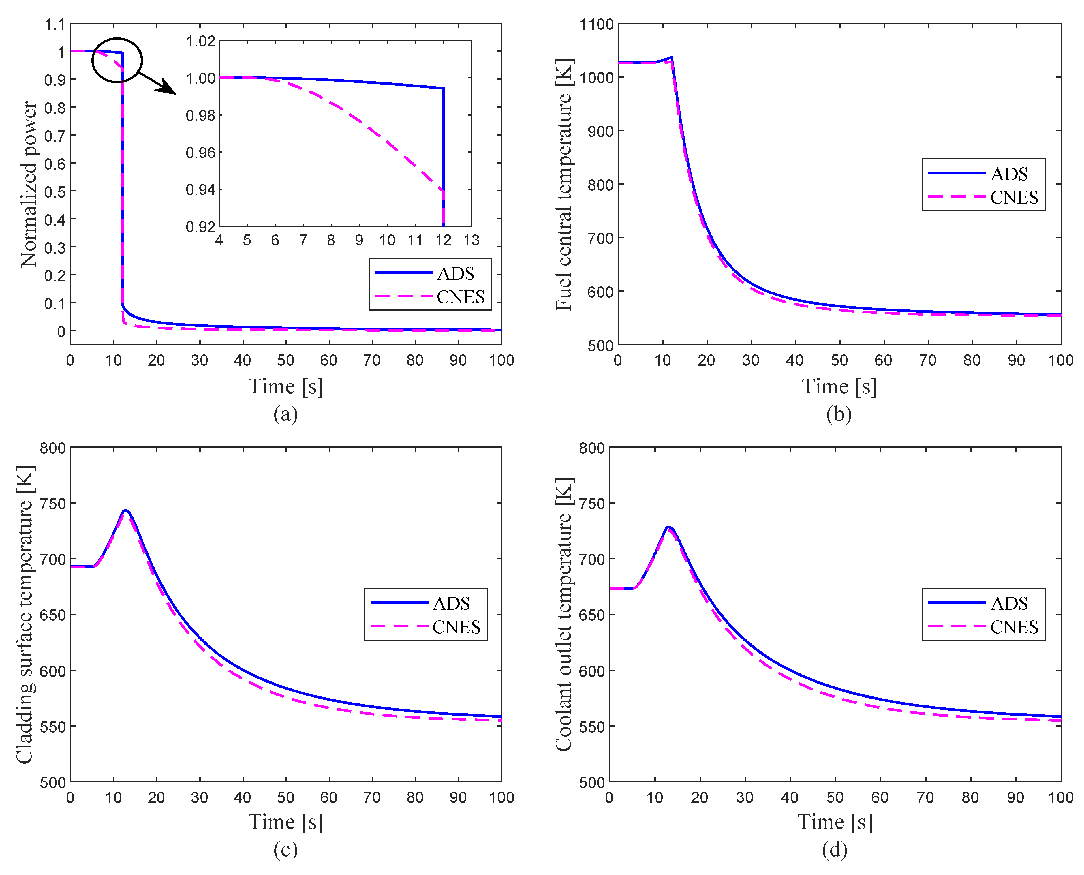
The transient responses of protected reactivity insertion for ADS and CNES are shown in
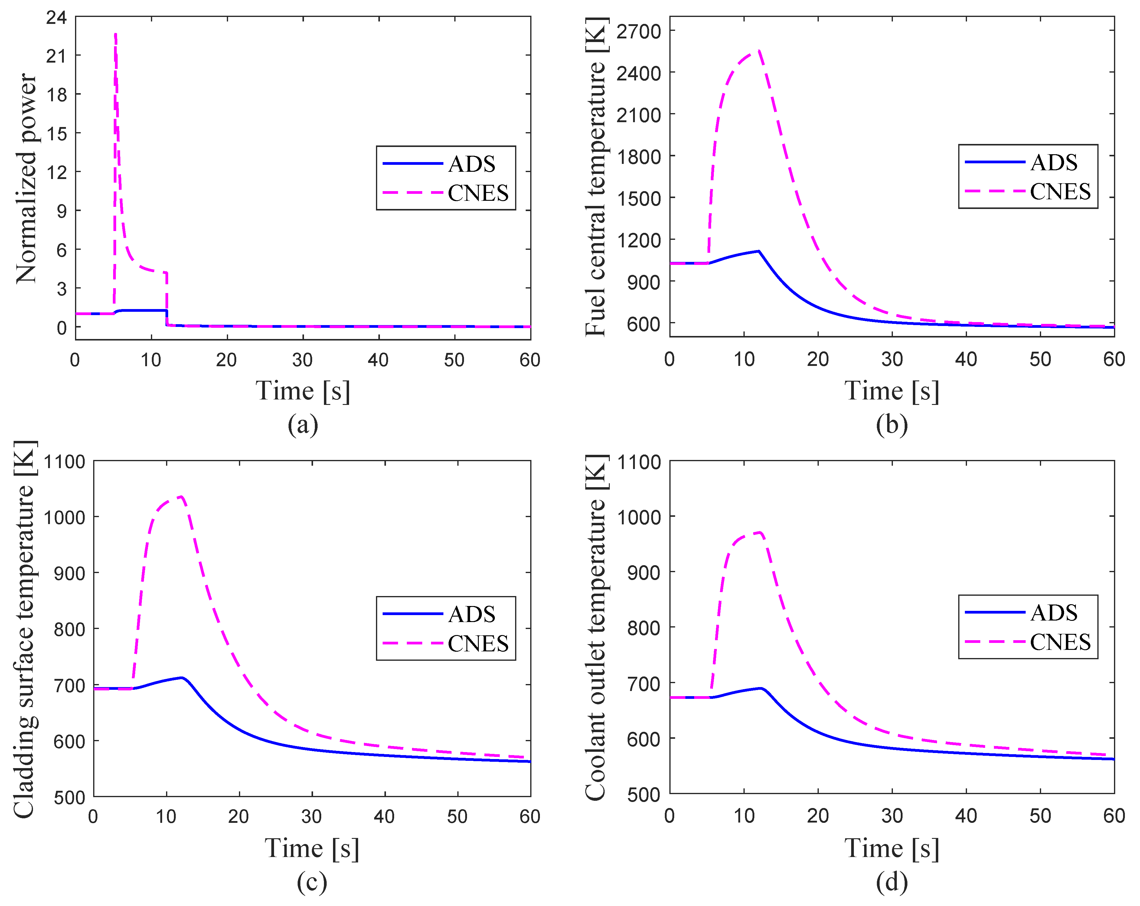
Figure 9, in which the positive reactivity is inserted at 5 s and then the shutdown protection system is activated at 12 s. For the ADS reactor, it can be seen that the power and the temperatures of fuel, cladding, and coolant sharply decrease to the safety level after the proton accelerator is closed. After introducing 700 pcm reactivity for the CNES reactor, the prompt supercritical accident occurs, and then the power and the fuel temperature rise sharply to very high values. With the rapid insertion of the safety control rod, the power declines to the shutdown level, and the peak temperatures of the fuel center and the cladding surface are 2552 K and 1035 K, respectively. It can be seen from
Figure 9c that the cladding still has a short-term rapture failure risk in the CNES reactor during this transient state.
3.2. Loss of Flow Accident
The influence of the pump trip on the mass flow rate was studied for loss of flow accident in the EBR-II fast reactor [
35]. In this work, the loss of flow accidents of ADS and CNES are simulated with ARTAP, in which the coolant mass flow in the core drops from 100% to 10% due to primary pump coastdown. Both unprotected and protected cases are considered.
3.2.1. Unprotected Loss of Flow
Figure 10 shows the transient responses of ADS and CNES for unprotected loss of flow due to primary pump coastdown. The mass flow rate of the reactor core drops rapidly after the primary coolant pump trips, which causes the heat produced by fission reaction in the fuel not to be able to be taken out in time, and the cladding temperature rises rapidly. As shown in
Figure 10c, the maximum cladding temperature in the ADS core reaches 1439 K, which means it has exceeded the damage limit. For one thing, the power drop is small due to the deep subcriticality of the ADS core and low sensitivity to negative reactivity feedback, which is from 100% full power to 90% level. Furthermore, the loss of flow rate prevents the heat transferral from the pellet to the coolant, so the temperature of the cladding rises to a very high value. Due to the negative reactivity introduced by the Doppler effect and the coolant temperature effect, the reactor power of CNES quickly decreases from 100% to 41%, and the cladding temperature rises to the peak point and then gradually decreases. The peak temperature of the cladding in the CNES core is only 1005 K, which is lower than the breakage limit. Results of comparison show that the inherent safety characteristics of the CNES core are better than those of the ADS core under loss of flow accident, and the protection system of ADS should be quickly activated to achieve an emergency shutdown after the accident occurs.
3.2.2. Protected Loss of Flow
The calculation results of the protected loss of flow are presented in
Figure 11, where the primary pump trips at 5 s, and the shutdown signal occurs at 12 s. It can be seen that the reactor power and the fuel temperature of both ADS and CNES drop rapidly and then reach the shutdown level after the protection system is activated. As shown in
Figure 11a, the reactor power of CNES declines faster than that of ADS. During this process, the maximum temperatures of the fuel center and the cladding surface in the ADS and CNES reactors are lower than the security limit. These simulation results indicate that the CNES system could ensure reactor shutdown by inserting safety control rod. It also implies that ADS could quickly restore to safety by cutting off the proton beam under loss of flow accident.
3.3. Loss of Heat Sink Accident
Corresponding to the primary circuit system, the secondary circuit system is a heat sink of the core during the normal operation of nuclear reactors. When the cooling system of the secondary circuit fails, such as all the secondary circuit pumps trip, insufficient cooling capacity of the core results in a heat sink accident [
36]. During the process of heat sink accident, all of the circuit pumps in the secondary loop fail, which causes a mass flow of the entire secondary circuit to drop from 100% to 8% within 20 s. Both unprotected and protected cases are examined in this work.
3.3.1. Unprotected Loss of Heat Sink
Transient responses of the ADS core and the CNES core for unprotected loss of heat sink due to all secondary pumps trip are shown in
Figure 12. Because the mass flow rate of the secondary side in the heat exchanger drops rapidly after the loss of heat sink accident, the heat of the primary circuit loop cannot be removed in time. It can be seen from
Figure 12d that the coolant inlet temperatures of both the ADS core and the CNES core rise rapidly. The power drops due to the negative feedback effect of reactivity, in which the reduction of the CNES power is much larger than that of the ADS power, thus the fuel central temperature of CNES rises slightly and then declines with the decrease of the power. During the loss of heat sink accident, the peak temperatures of the cladding surface in the ADS and CNES reactors are lower than the safety limit.
3.3.2. Protected Loss of Heat Sink
The simulation results of ADS and CNES for the protected loss of heat sink are shown in
Figure 13, where all secondary pumps stop at 5 s, and the shutdown signal occurs at 12 s. As the secondary circuit pumps all stop running, the mass flow rate of the secondary side in the heat exchanger (IHX) drops rapidly, and the outlet temperature of the primary side in the IHX rises, which means that the coolant inlet temperature of the core increases. With the rapid decrease of the reactor power due to the activation of the shutdown protection system, the temperatures of the fuel center and cladding surface also drop rapidly, and then the coolant inlet temperature gradually declines as well. These simulation results indicate that both the ADS and CNES systems have the inherent safety characteristics to ensure reactor a shutdown against loss of heat sink accident.
4. Conclusions
In the present study, a developed computational code named ARTAP is used to analyze and compare the safety characteristics between the LBE-cooled ADS and CNES. The developed code consists of a space–time neutron diffusion equation with a spallation neutron source model and a thermal-hydraulics model with a package of thermophysical properties, which could be used for calculations of both the LBE-cooled ADS and the LBE-cooled CNES. In order to investigate differences of the safety characteristics of these two reactors, three typical accidents are carried out, including reactivity insertion, loss of flow, and loss of heat sink. In addition, the accident simulations are not only performed in the case of unprotected transient, but also in the case of protected transient, i.e., transient with interruption of accelerator beam for ADS and with insertion of shutdown rod for CNES. The transient behaviors of the reactor power and the temperatures of the fuel, cladding, and coolant are investigated during the accident sequences.
The comparison results show the power and the temperatures of fuel pellet, cladding, and coolant of the CNES core are much higher than those of the ADS core during the reactivity insertion accident, which means ADS has a better safety advantage than CNES. However, due to the deep subcriticality of the ADS core and its low sensitivity to negative reactivity feedback, the simulation results indicate that the inherent safety characteristics of the CNES core are better than those of the ADS core under loss of flow accident, and the protection system of ADS would be quickly activated to achieve an emergency shutdown after the accident occurs. For the loss of heat sink, it is found that the peak temperatures of the cladding in the ADS and CNES reactors are lower than the safety limit, which mean these two reactors have good safety performance against loss of heat sink accident.


