Article

Rotation Accuracy Analysis of Aerostatic Spindle Considering Shaft’s Roundness and Cylindricity

1
School of Mechanical and Precision Instrument Engineering, Xi’an University of Technology, Xi’an 710048, China
2
School of Mechatronics Engineering, Zhongyuan University of Technology, Zhengzhou 451191, China
*
Author to whom correspondence should be addressed.
Appl. Sci. 2021, 11(17), 7912; https://doi.org/10.3390/app11177912
Submission received: 27 July 2021 / Revised: 23 August 2021 / Accepted: 25 August 2021 / Published: 27 August 2021
(This article belongs to the Special Issue Gas Bearings: Modelling, Design and Applications)

Abstract

:
The rotation accuracy of the aerostatic spindle can easily be affected by shaft shape errors due to the small gas film clearance. Thus, the main shaft shape errors with the largest scale—that is, the roundness and cylindricity errors—are studied in this paper, and a dynamic mathematical model is established with the consideration of the roundness, cylindricity errors, and spindle speed. In order to construct the shaft model, the discrete coefficient index of the shaft radius based on roundness measurement data are proposed. Then, the simulation calculations are conducted based on the measured cylindricity data and the constructed shaft model. The calculation results are compared with the spindle rotation accuracy measured using the spindle error analyzer. The results show that the shaft with a low discrete coefficient is subjected to less unbalanced force and smaller rotation errors, as obtained by the experiment.

1. Introduction

In contrast with traditional spindles, an aerostatic spindle uses compressed gas to form a gas film, which has the characteristics of high precision, high speed, and low noise. The film thickness of an aerostatic spindle is usually about 10 micrometers, which meets the high requirements regarding manufacturing errors relating to the shaft [1]. Manufacturing errors can be classified as dimensional errors and shape errors, which include roundness, cylindricity, waviness, and roughness. Shape errors of the shaft will cause the uneven distribution of the gas film in the bearing. When the shaft rotates, the thickness of the gas film in the bearing will change continuously, which will cause pressure fluctuation, and then produce an unbalanced force on the shaft. The unbalanced force will affect the stability and rotation accuracy of the spindle.
Pande et al. [2] pointed out that the shape errors of journal bearings can generally reduce the load-carrying ability and increase the flow rate. Song et al. [3] calculated the half frequency whirl phenomena and the instability threshold speeds for the bearings with shape errors. They found that the precision of the shaft is much more important than that of the bearing. Sun et al. [4] studied the effects of shape errors of a shaft-bearing system on dynamic characteristics, and results show that the rotating speed at which the fluid whip occurs increased when shape errors existed. In order to reduce the radial error motion, Cappa et al. [5] analyzed the influence of several manufacturing errors, bearing parameters and feeding geometries of an aerostatic journal bearing and suggested that the radial error motion is mainly influenced by the shape errors of the shaft. Cui et al. [6] presented research on the manufacturing errors of aerostatic porous journal bearings, and found that the circumferential waviness errors caused the obvious inhomogeneity of the flow field and the transformation of the morphology of the high-pressure region. Zhang et al. [7] established a new approximate model to predict the radial error motion of hydrostatic journal bearings, and pointed out that the main working harmonic components in roundness errors had a major influence over rotation accuracy. Wang et al. [8] proposed a numerical model using linear perturbation theory for the research on the influence of journal rotation and bearing surface waviness on the dynamic performance of aerostatic journal bearings. Lee et al. [9] examined the influence of the waviness errors of a hydrostatic journal bearing by considering the rotational and bearing installation angles, and revealed that the load-carrying capacity varied according to the amplitude and phase angle of the waviness functions. Li et al. [10] investigated the effects of different forms of surface waviness on the stability of the hydrodynamic journal bearing system by using non-linear dynamic analysis and calculation method, and the results show that the existence of the surface waviness causes the oil film of the system to wave and increases the energy loss of the system. In order to study the surface roughness effects in hydrodynamic bearings, Quiñonez et al. [11] developed an analytical solution method based on the Reynolds equation using perturbation techniques under the assumption of waviness coupled with linear superposition that can be used in wide exponential land slider bearings. Lin [12] analyzed the effect of surface roughness on the dynamic stiffness and damping characteristics of hydrostatic thrust bearings; according to the results, the mean stiffness and damping behaviours are significantly affected by the roughness pattern and the height of the roughness. Kumar et al. [13] studied the effect of stochastic roughness on performance of a Rayleigh step bearing operating under thermo-elastohydrodynamic lubrication. The results show that the directional orientation of the surface roughness could affect the performance of a bearing significantly. Based on the stochastic method and the Ng–Pan turbulent model, Zhu et al. [14] calculated the turbulent lubrication performance of a journal bearing with an isotropic rough surface. Kim et al. [15] proposed an approach with both stochastic and contact characteristics to evaluate the effects of surface roughness for a slider bearing operating under partial or boundary lubrication, and found that the influence of roughness parameters on friction and load capacity increased rapidly upon the application of asperities contact. Maharshi et al. [16] proposed a stochastic analysis of hydrodynamic journal bearings including the effect of surface roughness and development of the efficient radial basis function based uncertainty quantification algorithm. By using Galerkin’s technique to solve the Reynolds equation, Rajput [17] indicated that the performance of a journal bearing system is significantly deteriorated due to the geometric imperfections.
In the above references, the waviness and roughness in the shaft shape errors are mostly studied. However, the roundness and cylindricity are the largest errors among the shaft shape errors, usually between 1 and 4 micrometers. These errors have the most obvious impact on the aerostatic spindle’s rotation accuracy. Although Zhang et al. [7] studied the radial error motion of the bearing in a quasi-static state considering roundness errors of the shaft, the rotation accuracy of the aerostatic spindle will change with rotation speed, which is not considered in the present study. Therefore, it is necessary to study the dynamic rotation accuracy of the aerostatic spindle under the effects of roundness and cylindricity errors.
Therefore, a dynamic mathematical model considering roundness, cylindricity errors and spindle speed is established by using the finite difference method based on the Reynolds equation in this paper. The roundness and cylindricity errors of the shaft are measured by Taylor Hobson 585 LT cylindricity meter. The measured data are resampled and filtered and then brought into the model for calculation. Through the comparison of the simulation and the experiment, it is proved that the shaft roundness and cylindricity errors will produce an unbalanced gas film force on the shaft and affect the spindle’s rotation accuracy. Based on the measurement data of roundness error, the evaluation index of the dispersion coefficient is proposed. The research shows that this discrete coefficient is a more effective index to predict the spindle’s rotation accuracy compared with the roundness and cylindricity.

2. Mathematical Model

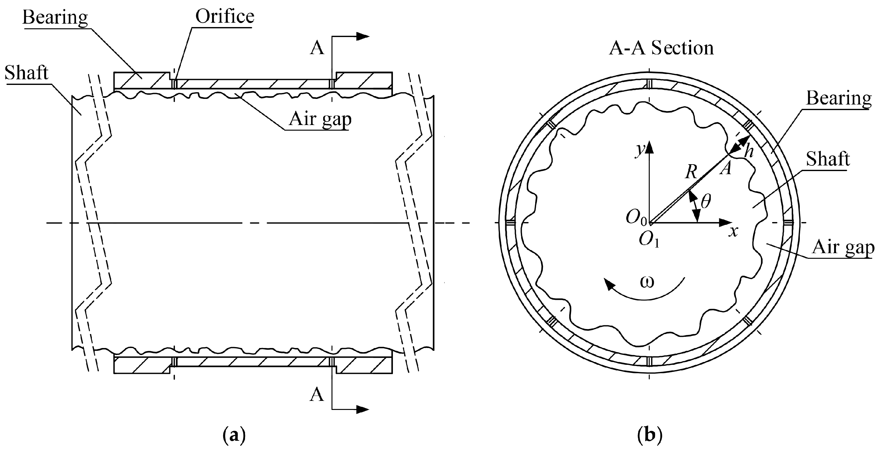
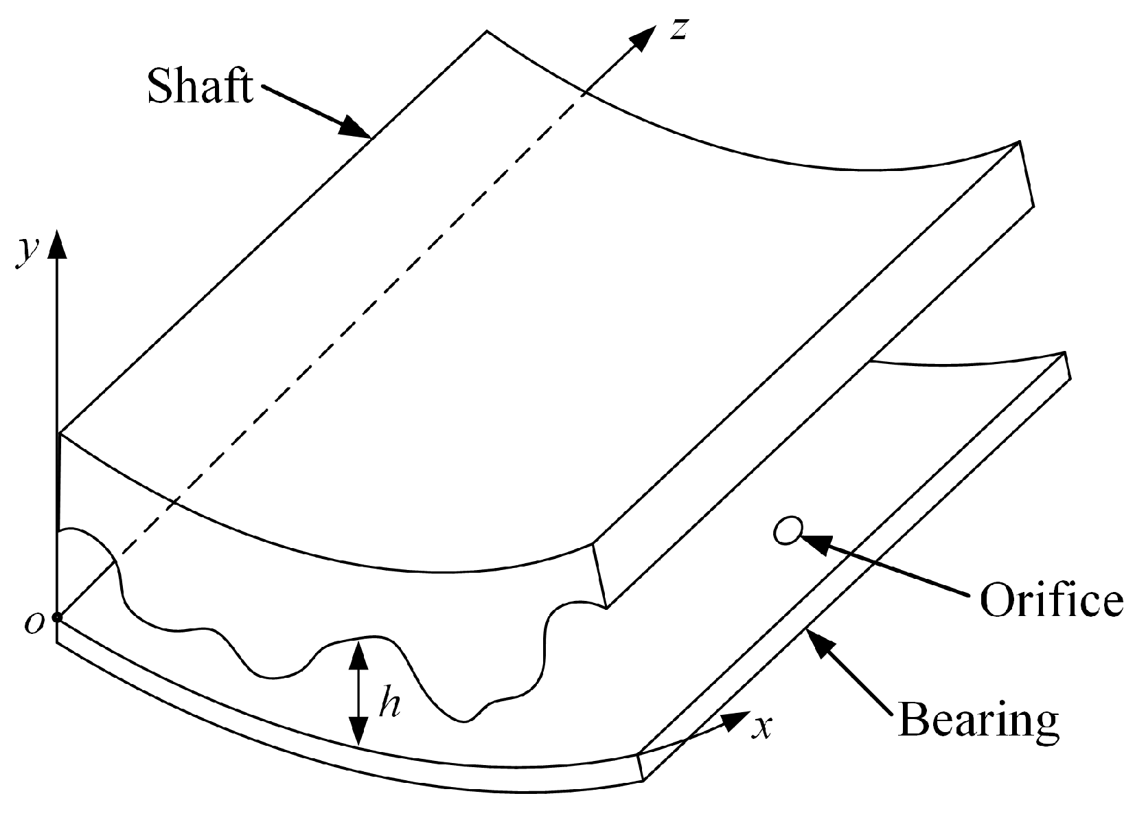
2.1. Modeling of the Aerostatic Spindle

The schematic illustration of the aerostatic journal bearing with shaft shape errors is shown in Figure 1. This bearing has two column orifice restrictors at the front and rear, and each column includes eight orifices. The compressed gas flows into the clearance between the bearing and the shaft through the orifice, and then flows out from both ends of the bearing.
Due to the shape errors of shaft surface, the film thickness of different positions in the circumferential and axial directions of the bearing is different. In Figure 1b, O 0 is the bearing center, O 1 is the shaft center, and R is the bearing radius. h is the film thickness at point A on the shaft surface that can be denoted as
h = R O 0 O 1 + O 1 A
When θ is the angle between O 0 A and the x-axis, O 0 O 1 = ( e x , e y ) , and O 1 A = ( c x θ , c y θ ) , the film thickness at θ is
h θ = R c x θ + e x 2 + c y θ + e y 2
If the shaft is rotating clockwise at a constant angular velocity ω , then at t time,
θ = θ + ω t + α 2 N π c x θ = x θ c y θ = y θ
where α is the initial angle of the shaft, N is the integer number of rotations of the shaft, and the values of x θ and y θ come from the measurement results of the cylindricity meter.
By combining Equations (2) and (3), the film thickness at any angle at any time can be obtained.
In order to study the pressure distribution of the gas film in the bearing, the circumferential cylindrical coordinates system is used to reconstruct the journal bearing. Figure 2 is the partial schematic illustration of aerostatic journal bearing in circumference cylindrical coordinates. The circumferential direction of bearing’s inner surface is the x-axis and the y-axis points and is perpendicular to the bearing axis, and the z-axis is parallel to the bearing axis.
This spindle system incorporates the following assumptions:
  • The spindle is cooled sufficiently—that is, the bearing, shaft and gas film is isothermal;
  • There is no axial and angular movement of the shaft;
  • The gas flow is laminar.
The modified Reynolds equation for this type of aerostatic journal bearing [18] is
x p h 3 p x + z p h 3 p z = 6 η u ( p h ) x + 12 η ( p h ) t + 12 η p V i n
where p is the gas film pressure, η is the dynamic viscosity of the gas, u is the velocity of the gas in x direction, and V i n is the injection velocity at the orifice entrance and can be expressed by Equation (5) [19]
V in = P s p 4 η l [ d 2 4 ( x x i ) 2 ( z z i ) 2 ] · δ i
where δ i = 1 at the orifice entrance, whereas it is zero elsewhere.
By employing the dimensionless parameters
x = x 0 X , z = z 0 Z , h = h 0 H , t = τ x 0 u , p = p a P , Λ = 12 η u x 0 h 0 2 p a , Q = 24 η x 0 2 h 0 3 p a 2 V i n
Equation (4) can be written as:
X H 3 P 2 X + x 0 2 z 0 2 Z H 3 P 2 Z = Λ P H X + 2 Λ P H τ + Q P

2.2. Numerical Analysis

With reference to paper [20], some items in Equation (7) are rewritten as follows by using the finite difference method:
X H 3 P 2 X = H i + 0.5 , j 3 Δ X 2 P i + 1 , j 2 P i , j 2 H i 0.5 , j 3 Δ X 2 P i , j 2 P i 1 , j 2
Z H 3 P 2 Z = H i , j + 0.5 3 Δ Z 2 P i , j + 1 2 P i , j 2 H i , j 0.5 3 Δ Z 2 P i , j 2 P i , j 1 2
P H X = H i + 0.5 , j H i 0.5 , j 2 Δ X P i , j + H i + 0.5 , j 2 Δ X P i + 1 , j H i 0.5 , j 2 Δ X P i 1 , j
P H τ = H i , j Δ τ P i , j H ( τ Δ τ ) ( i , j ) Δ τ P ( τ Δ τ ) ( i , j )
where H ( τ Δ τ ) ( i , j ) and P ( τ Δ τ ) ( i , j ) in Equation (11) are H i , j and P i , j in ( τ Δ τ ) time, respectively.
By substituting Equations (8)–(11) into Equation (7), the equation is simplified as
E i , j P i , j 2 + ( F i , j + I i , j ) P i , j K i , j = 0
with
A i , j = H i + 0.5 , j 3 Δ X 2
B i , j = H i 0.5 , j 3 Δ X 2
C i , j = x 0 2 z 0 2 H i , j + 0.5 3 Δ Z 2
D i , j = x 0 2 z 0 2 H i , j 0.5 3 Δ Z 2
E i , j = A i , j + B i , j + C i , j + D i , j
F i , j = Λ H i + 0.5 , j H i 0.5 , j 2 Δ X
G i , j = Λ H i + 0.5 , j 2 Δ X
H i , j = Λ H i 0.5 , j 2 Δ X
I i , j = 2 Λ H i , j Δ τ + Q
J i , j = 2 Λ H ( t Δ τ ) ( i , j ) Δ τ
K i , j = A i , j P i + 1 , j 2 + B i , j P i 1 , j 2 + C i , j P i , j + 1 2 + D i , j P i , j 1 2 G i , j P i + 1 , j H i , j P i 1 , j J i , j P ( t Δ τ ) ( i , j )
The dimensionless gas film pressure in τ time is given by
P i , j = ( F i , j + I i , j ) 2 + 4 E i , j K i , j F i , j I i , j 2 E i , j

3. Data Acquisition and Processing

In addition to the basic parameters of the spindle, it is necessary to know the initial distribution of the gas film to solve the pressure distribution using Equation (24). That is, the H of any node at τ = 0 time is needed, which is very critical. It can be seen from Equations (2), (3), and (6) that in order to calculate H, the shape errors of the shaft should be measured. A cylindricity meter was used to measure the roundness and cylindricity errors for study in this paper.

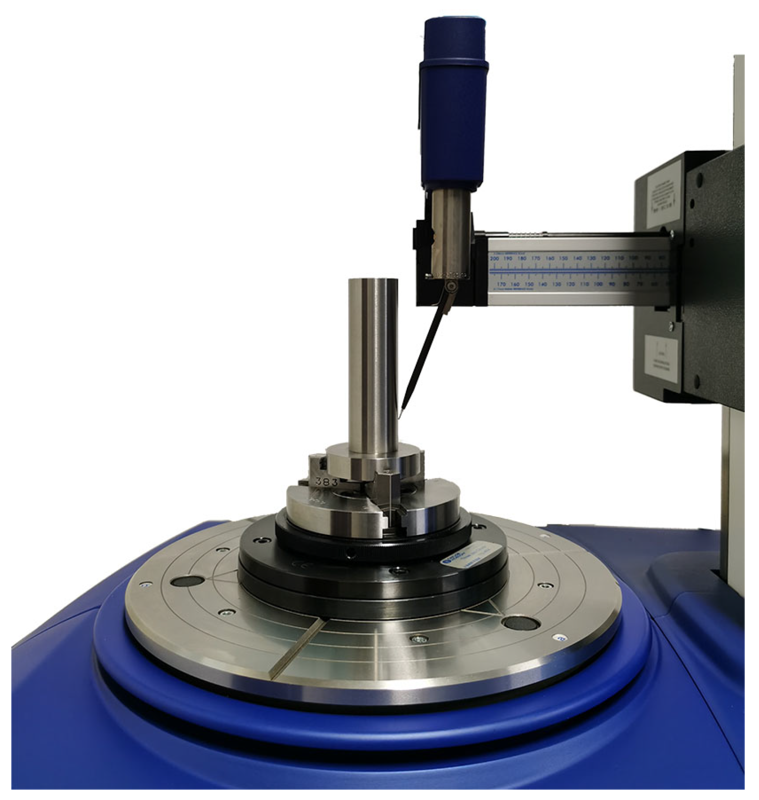
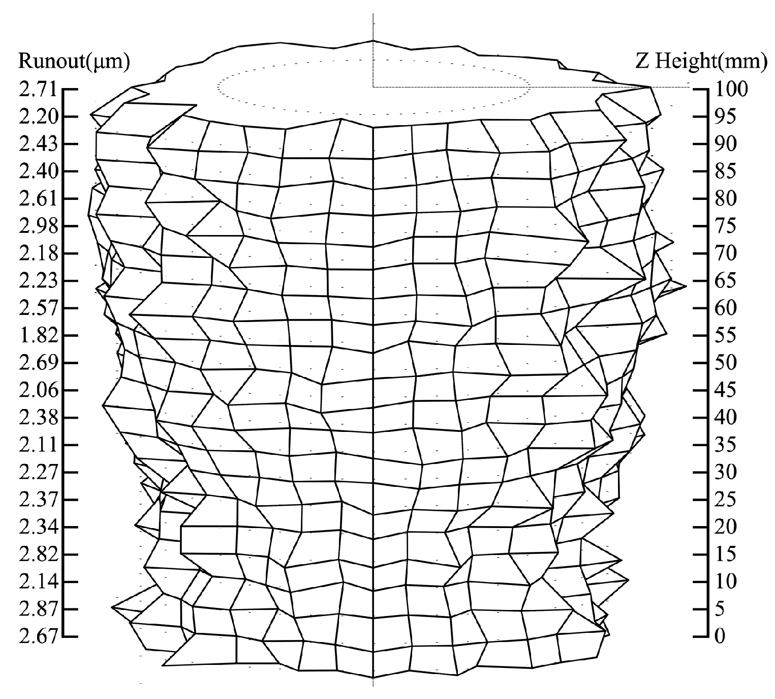
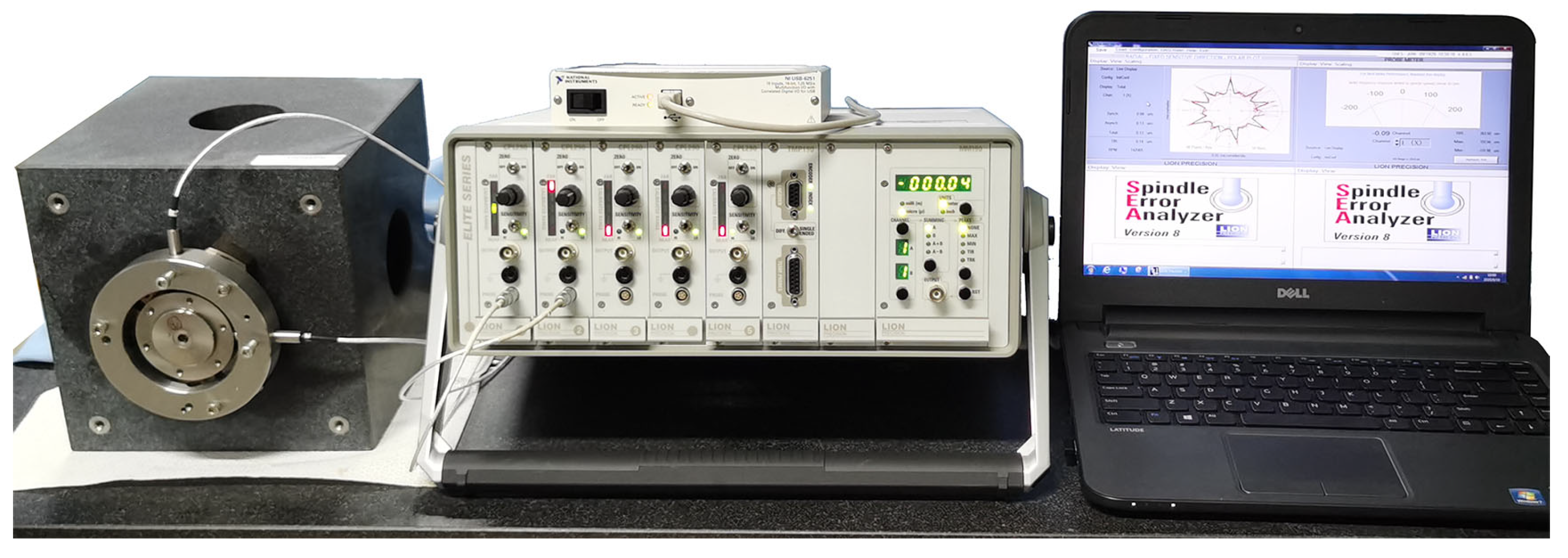
3.1. Roundness and Cylindricity Errors Measurement of Shaft

In this paper, we processed 4 shafts with the same parameters and technique. The roundness and cylindricity errors of the working area of these shafts corresponding to the journal bearing was measured using the Taylor Hobson 585 LT cylindricity meter, and 21 sections of each shaft were collected. The section interval was 5 mm, and the number of sampling points was 18,000 points per section. Figure 3 shows the roundness and cylindricity error measurement process, and the cylindricity error results of shaft 1 are shown in Figure 4. The data on the left-hand side represent the runout of each section, which is equal to the roundness errors under the least square method. The data on the right side represent the measured height. The cylindricity errors of four shafts are 4.00, 4.50, 4.25, and 4.15 μ m, respectively.

3.2. Data Processing

Since the data collected by the cylindricity meter were based on relative coordinates, it was necessary to calibrate the measured data with the actual radius of the shaft. The calculation method is shown in Equation (25)
x θ = x c θ R c x c θ 2 + y c θ 2 y θ = y c θ R c x c θ 2 + y c θ 2
where x c θ and y c θ are the data collected by cylindricity meter, and R c is the shaft radius measured by micrometer.
In the data measured by cylindricity meter, each section had 18,000 data points. The average value of each adjacent 50 data points was taken to save the computing time, and the number of data points was reduced to 360. Gaussian filter was used for roundness filtering with 150 UPR (undulations per revolution) cut-off [21]. The number of axial nodes increased from 21 to 41 by using Equation (26)
h i , k + 0.5 = h i , k + h i , k + 1 2 ( k = 1 , 2 , , 20 )

3.3. Calculation Settings

Programs were compiled according to Equations (7)–(24); Table 1 shows the parameters of the spindle. The measured data of shaft 1, shaft 2, shaft 3, and shaft 4 were used for calculation, respectively. The initial eccentricity was ( e x , e y ) = ( 0 , 0 ) , and the speed range was [500, 10,000] r/min.

4. Results and Discussions

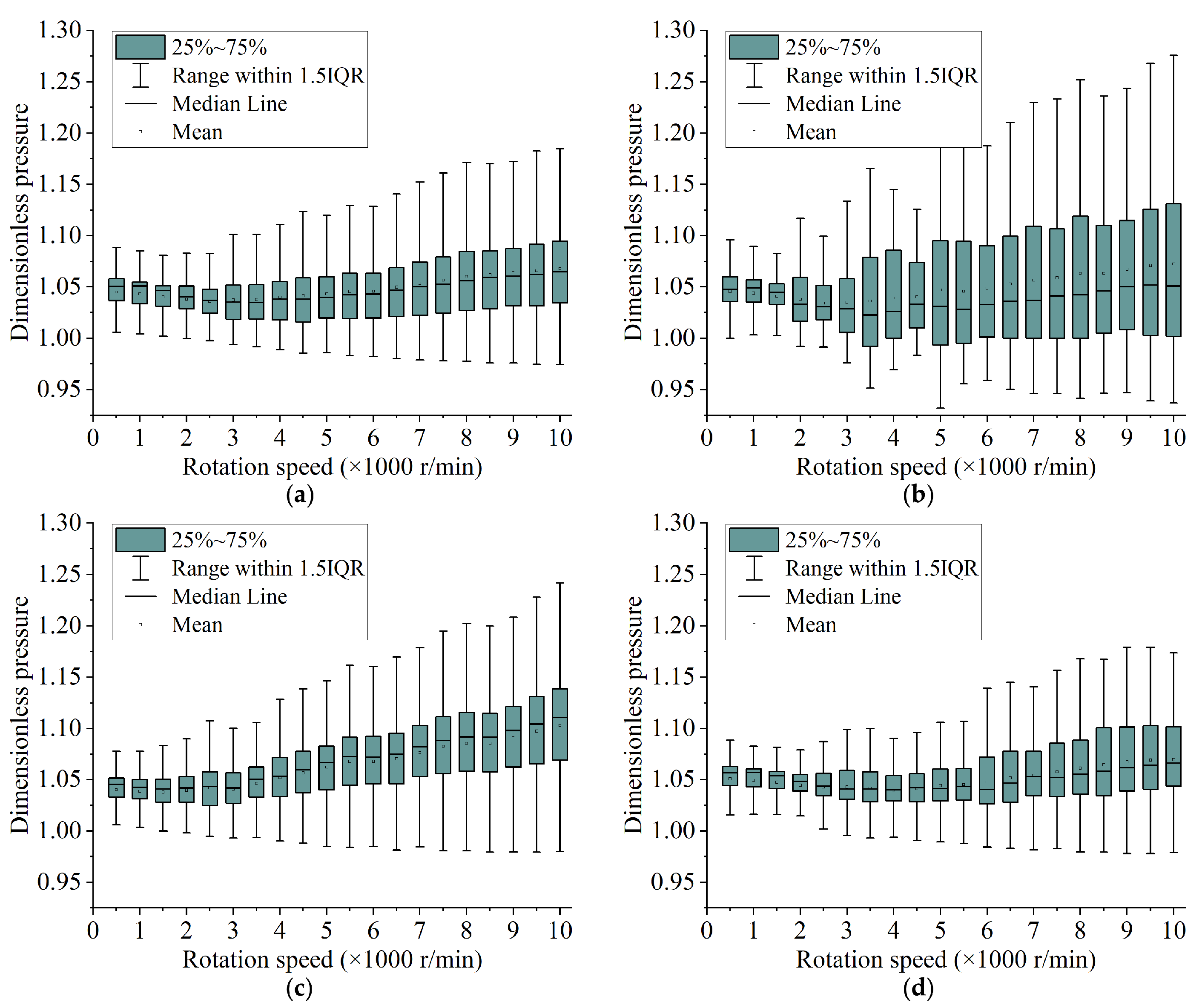
4.1. Simulation Results

First of all, an ideal shaft without shape errors is used for the calculation to verify the correctness of the numerical model and the simulation program; Figure 5 shows the result of dimensionless pressure distribution when the shaft rotates 180 at 6000 r/min. It can be seen that the pressure distribution on the shaft surface is very regular, which is consistent with the calculation results in reference [22]. In this ideal case, the gas film force acting on the shaft is zero.
Figure 6a–d show the dimensionless pressure distribution of shaft 1 at 6000 r/min when it rotates 90 , 180 , 270 and 360 with the same coordinate scales, respectively. Due to the roundness and cylindricity errors, the gas pressure on the shaft surface varies greatly. As the shaft rotates, the pressure changes obviously. Thus, the shaft will produce an unbalanced gas film force, which changes both in size and direction, and then affects the rotary accuracy of the spindle.
Figure 7a–d are box charts of the surface pressure distribution of shaft 1, shaft 2, shaft 3, and shaft 4 at different speeds with the same coordinate scales. With the increase in rotating speed, the distribution of pressure value becomes more and more divergent. By comparing the interquartile range (IQR) and the range within 1.5IQR of the dimensionless pressure in Figure 7a–d, it can be observed that the pressure fluctuation of shaft 2 is significantly greater than that of the other three shafts.
If the pressure is known, the gas film force acting on the shaft can be calculated using Equation (27) [23]:
F x F y = 0 L 0 2 π p p a t m cos θ sin θ r d θ d z
Figure 8a shows the gas film force (with 5 revolutions) of shaft 1 at 6000 r/min. With the rotation of the shaft, the direction and size of the force change, and the shaft adopts an unsteady state. Plotting the average force of the shaft at different speeds in Figure 8b, it can be seen that with the increase in speed, the force on the shaft increases basically. The force of shaft 2 at each speed is significantly higher than that of the other three shafts. According to the force from large to small, the order is as follows: shaft 2 > shaft 1 > shaft 4 > shaft 3.

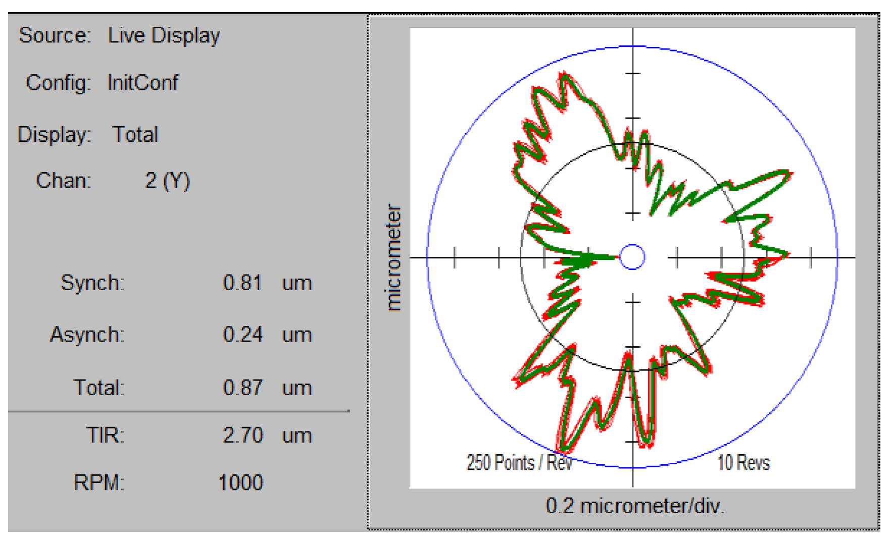
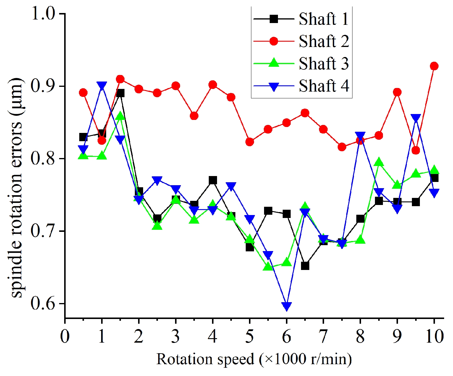
4.2. Comparison with Experimental Results

The aerostatic spindle used in this paper to validate the simulation results is mainly used for precision milling. For ensuring the stability of continuous running, the spindle is water-cooled. The four shafts are fitted into the spindle in turn, and the bearing, motor and other parts are installed. The motor is a Kollmorgen KBMS-10X01 frameless motor with the rated speed of 18,600 r/min. The driver belongs to Sieb and Meyer’s SD2S series. After two stages of drying and filtering, the gas supply pressure is set to 0.4 Mpa (same as the numerical calculation). This system is mounted on a natural granite cubic base with a side length of 200 mm. For the consistency of the measurement results, other parts and related configurations remain unchanged throughout the test, except for the replacement of the shaft.
Using sensors to measure the standard gauge installed on the spindle, the rotation errors are usually measured without load, and the track of the ideal axis of the rotation of the spindle is fitted as the basis of the analysis. Due to the small size of the spindle, there is not enough space to install the standard gauge and there is a section of finish-machined cylinder in the front of the shaft as an alternative.
The dynamic radial rotation errors were measured using the Lion Precision CPL290 spindle errors analysis instrument. The bandwidth of the sensor is 15 kHz and the resolution is 0.01 μ m. The spindle speed range is set to 500 to 10,000 r/min, and the data are collected every 500 r/min. Figure 9 is the test rig of the spindle rotation error measurement, and the results of shaft 1 at 1000 r/min are shown in Figure 10. Following measurement, the data of the four shafts are plotted in Figure 11.
As can be seen from Figure 11, in the rotation speed range of [500, 10,000] r/min, the rotation radial errors of shaft 1, shaft 3 and shaft 4 are always close to each other, except for individual speeds. When the speed exceeds 2000 r/min, the errors of shaft 2 are obviously larger than those of the other three shafts, and the “particularity” of shaft 2 in Figure 11 is consistent with that in Figure 7 and Figure 8b. In the analysis results of Figure 7 and Figure 8, the original data are obtained from the measurement of the roundness and cylindricity errors of the shaft. It can be seen that there must be a correlation between the measurement results of the roundness and cylindricity errors of the shaft and the rotation errors.
The roundness errors of all shaft sections measured using the cylindricity meter are plotted, as shown in Figure 12. It can be seen that the roundness error lines of the four shafts overlap with each other and the difference is not obvious. For example, the roundness error values of section 11 of shaft 1 and section 15 of shaft 2 are both 2.69 μ m, and the roundness error values of section 19 of shaft 2 and section 10 of shaft 4 are both 2.25 μ m. Figure 13 is a composite drawing of roundness errors for section 19 of shaft 2 and section 10 of shaft 4. It can be seen that although the roundness errors values are the same (2.25 μ m), their actual shapes are quite different. Therefore, the roundness error values cannot reflect the shape of the shaft.

4.3. Evaluation with Dispersion Coefficient

The shape of the shaft determines the gas film thickness between the shaft and the matched bearing. The more uniform the film thickness, the smaller the pressure fluctuation in the shaft; therefore, the discrete coefficient index of shaft radius can be used to quantify the section shape of the shaft. The calculation is conducted by means of Equation (28):
V S = 1 r 0 1 n 1 i = 1 n r i r 0 2
where n is the node number of single section, r i is the radius of the shaft at the i-th node, and r 0 is the average radius of the shaft in the current section.
The radius dispersion coefficients of all sections are calculated using Equation (28) and the results are plotted in Figure 14. It can be seen that the dispersion coefficients of all sections of shaft 2 are significantly larger than those of the other three shafts, which indicates that there are great fluctuations in radius for each section of shaft 2. The particularity results here are consistent with those shown in Figure 7, Figure 8 and Figure 11. Although the roundness errors of section 19 of shaft 2 and section 10 of shaft 4 are identical, the differences in the dispersion coefficients shown in Figure 14 are significant. Therefore, it is not reliable to infer the shaft’s rotational accuracy based on only its roundness and cylindricity errors.
To further study this problem, sections with similar roundness errors (see Table 2) and similar discrete coefficients (see Table 3) are found from all cross sections of four shafts to construct the ideal shafts (Figure 15 is a schematic diagram), and then the unbalanced gas film forces are analyzed in Figure 16. Because the shaft is constructed with a single section, the roundness errors are equal to the cylindricity errors. Figure 16a,b have the same coordinate scales to ensure the comparability of data.
It can be observed from Figure 16a that, although these shafts have the same roundness, the unbalanced film forces of these four shafts are quite different. The order of the force from large to small is section 19 of shaft 2 > section 7 of shaft 1 > section 10 of shaft 4 > section 1 of shaft 3, which is consistent with the order of the discrete coefficients in Table 2. As presented in Figure 16b, for the similar dispersion coefficient, the forces of the four shafts are generally similar, the lowest of which is for section 2 of shaft 1. In Table 3, the roundness errors of section 2 of shaft 1 is the largest among the four ideal shafts, but its discrete coefficient is the smallest. It can be proved that, compared with roundness errors, the discrete coefficient can be used more reliably to predict the unbalanced film force generated by the shaft due to the shape errors. In addition, when the results are combined with the data in Table 2 and Table 3, it can be seen that if the roundness is similar, the discrete coefficient may be very different, but if the discrete coefficient is similar, the roundness difference is not large, so the discrete coefficient can be used to evaluate the processing quality of the shaft.

5. Conclusions

In this paper, the roundness and cylinder error data of the shaft are collected by the Taylor Hobson cylinder meter as the data source of FDM simulation. The influence of shaft shape errors on spindle rotation accuracy is verified by comparing the simulation results with experimental results. The following conclusions have been drawn.
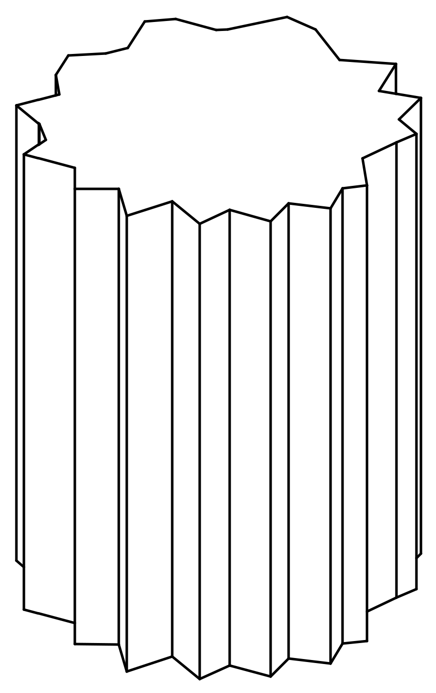
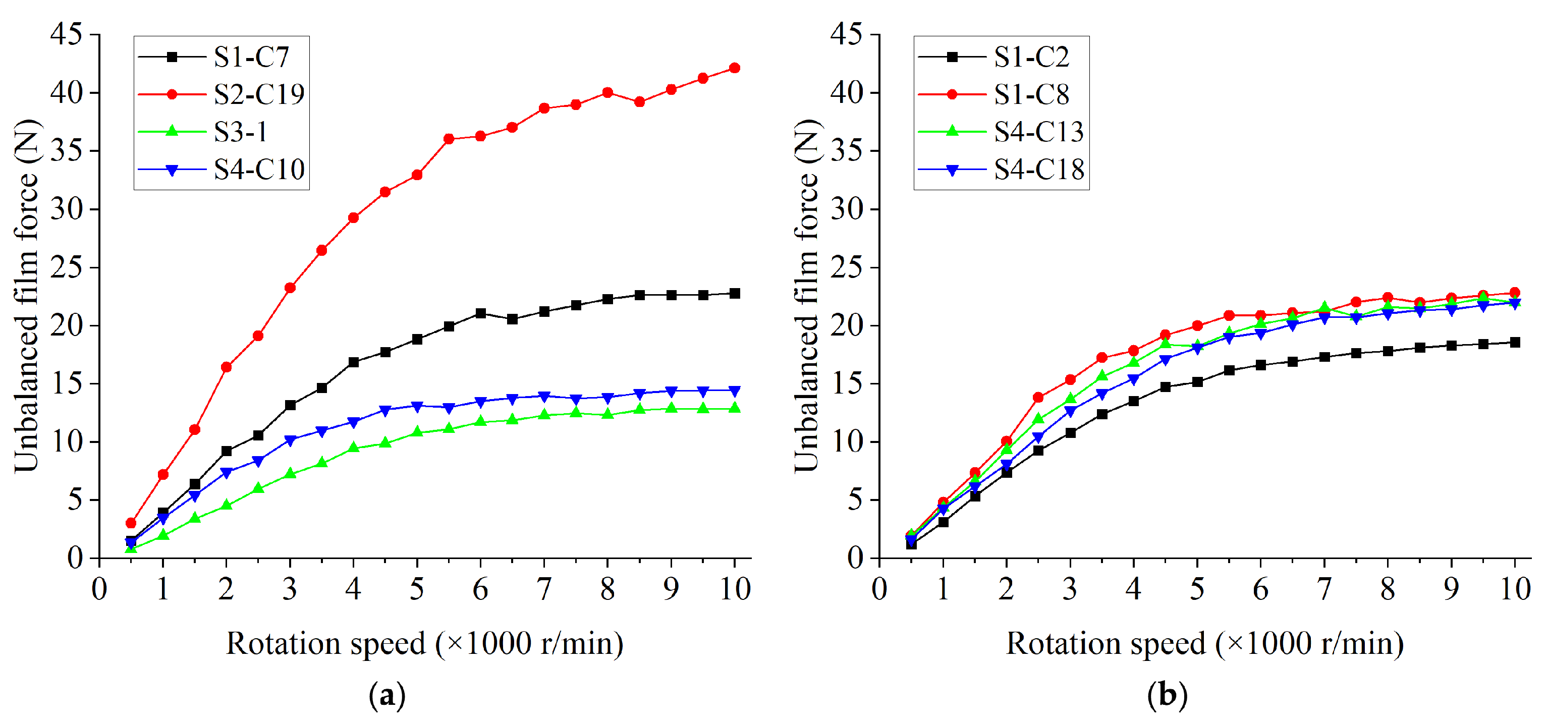
  • Because of the errors of roundness and cylindricity in the shaft, the film thickness inside the spindle will be different at different places, resulting in an uneven distribution of film pressure. With the rotation of the shaft, the pressure of the gas film will keep changing, resulting in an unbalanced film force, which will affect the stability of the spindle;
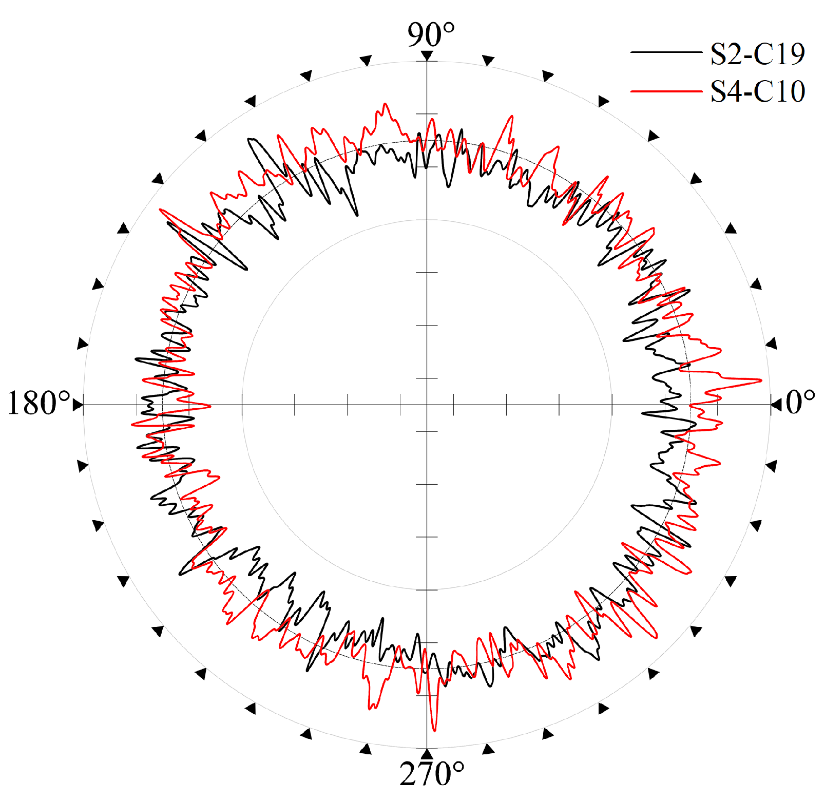
  • The errors of roundness and cylindricity of the shaft can not adequately reflect the distribution of film thickness inside the spindle. Shafts with similar errors may have large differences in unbalanced film force and rotation errors;
  • The dispersion coefficient reflects the fluctuation of the shaft radius. Shafts with similar discrete coefficients will not demonstrate much difference in their roundness error values, and the unbalanced film forces acting on the shaft during rotation are close to each other. Compared with roundness and cylindricity errors, the discrete coefficient is a better index to predict the spindle rotation accuracy. Therefore, during the design and manufacturing process of the spindle, the shaft radius dispersion coefficient should be controlled and measured for better spindle rotation accuracy.

Author Contributions

Conceptualization, G.Z.; methodology, J.Z.; software, G.Z. and H.Y.; validation, R.Z. and W.S.; formal analysis, J.Z. and H.Y.; investigation, J.Z. and H.Y.; data curation, G.Z. and J.W.; writing—original draft preparation, G.Z.; writing—review and editing, J.Z. and J.W.; visualization, R.Z. and W.S.; funding acquisition, J.Z. and H.Y. All authors have read and agreed to the published version of the manuscript.

Funding

This research was funded by the National Natural Science Foundation of China, grant number 51875586; training plan for young backbone teachers in colleges and universities of Henan province, grant number 2018GGJS105.

Institutional Review Board Statement

Not applicable.

Informed Consent Statement

Not applicable.

Data Availability Statement

The data presented in this study are available on reasonable request from the corresponding author.

Conflicts of Interest

The authors declare no conflict of interest.

References

  1. Gao, Q.; Chen, W.; Lu, L.; Huo, D.; Cheng, K. Aerostatic bearings design and analysis with the application to precision engineering: State-of-the-art and future perspectives. Tribol. Int. 2019, 135, 1–17. [Google Scholar] [CrossRef]
  2. Pande, S.; Somasundaram, S. Effect of manufacturing errors on the performance of aerostatic journal bearings. Wear 1981, 66, 145–156. [Google Scholar] [CrossRef]
  3. Song, M.; Azam, S.; Jang, J.; Park, S.S. Effect of shape errors on the stability of externally pressurized air journal bearings using semi-implicit scheme. Tribol. Int. 2017, 115, 580–590. [Google Scholar] [CrossRef]
  4. Sun, F.; Zhang, X.; Wang, X.; Su, Z.; Wang, D. Effects of Shaft Shape Errors on the Dynamic Characteristics of a Rotor-Bearing System. J. Tribol. 2019, 141. [Google Scholar] [CrossRef]
  5. Cappa, S.; Reynaerts, D.; Al-Bender, F. Reducing the radial error motion of an aerostatic journal bearing to a nanometre level: Theoretical modelling. Tribol. Lett. 2014, 53, 27–41. [Google Scholar] [CrossRef]
  6. Cui, H.; Wang, Y.; Yue, X.; Huang, M.; Wang, W.; Jiang, Z. Numerical analysis and experimental investigation into the effects of manufacturing errors on the running accuracy of the aerostatic porous spindle. Tribol. Int. 2018, 118, 20–36. [Google Scholar] [CrossRef]
  7. Zhang, P.; Chen, Y.; Liu, X. Relationship between roundness errors of shaft and radial error motions of hydrostatic journal bearings under quasi-static condition. Precis. Eng. 2018, 51, 564–576. [Google Scholar] [CrossRef]
  8. Wang, X.; Xu, Q.; Huang, M.; Zhang, L.; Peng, Z. Effects of journal rotation and surface waviness on the dynamic performance of aerostatic journal bearings. Tribol. Int. 2017, 112, 1–9. [Google Scholar] [CrossRef]
  9. Lee, S.M.; Lee, D.W.; Ha, Y.H.; Lee, S.J.; Hwang, J.H.; Choi, Y.H. A study on the influence of waviness error to a hydrostatic bearing for a crankshaft pin turner. Tribol. Trans. 2013, 56, 1077–1086. [Google Scholar] [CrossRef]
  10. Li, B.; Zhou, D.; Xu, W.; Zhang, Y. Effect of Surface Waviness on Stability of Hydrodynamic Journal Bearing Systems. J. Mech. Eng. 2019, 55, 51–59. [Google Scholar] [CrossRef] [Green Version]
  11. Quiñonez, A.F.; Morales-Espejel, G. Surface roughness effects in hydrodynamic bearings. Tribol. Int. 2016, 98, 212–219. [Google Scholar] [CrossRef]
  12. Lin, J.R. Surface roughness effect on the dynamic stiffness and damping characteristics of compensated hydrostatic thrust bearings. Int. J. Mach. Tools Manuf. 2000, 40, 1671–1689. [Google Scholar] [CrossRef]
  13. Kumar, R.; Azam, M.S.; Ghosh, S.K. Influence of stochastic roughness on performance of a Rayleigh step bearing operating under Thermo-elastohydrodynamic lubrication considering shear flow factor. Tribol. Int. 2019, 134, 264–280. [Google Scholar] [CrossRef]
  14. Zhu, S.; Sun, J.; Li, B.; Zhao, X.; Wang, H.; Teng, Q.; Ren, Y.; Zhu, G. Stochastic models for turbulent lubrication of bearing with rough surfaces. Tribol. Int. 2019, 136, 224–233. [Google Scholar] [CrossRef]
  15. Kim, M.; Lee, S.M.; Lee, D.W.; Park, S.; Kim, S. Tribological effects of a rough surface bearing using an average flow analysis with a contact model of asperities. Int. J. Precis. Eng. Manuf. 2017, 18, 99–107. [Google Scholar] [CrossRef]
  16. Maharshi, K.; Mukhopadhyay, T.; Roy, B.; Roy, L.; Dey, S. Stochastic dynamic behaviour of hydrodynamic journal bearings including the effect of surface roughness. Int. J. Mech. Sci. 2018, 142–143, 370–383. [Google Scholar] [CrossRef]
  17. Rajput, A.K.; Sharma, S.C. Combined influence of geometric imperfections and misalignment of journal on the performance of four pocket hybrid journal bearing. Tribol. Int. 2016, 97, 59–70. [Google Scholar] [CrossRef]
  18. Pierart, F.G.; Santos, I.F. Active lubrication applied to radial gas journal bearings. Part 2: Modelling improvement and experimental validation. Tribol. Int. 2016, 96, 237–246. [Google Scholar] [CrossRef] [Green Version]
  19. Morosi, S.; Santos, I.F. On the modelling of hybrid aerostatic-gas journal bearings. Proc. Inst. Mech. Eng. Part J J. Eng. Tribol. 2011, 225, 641–653. [Google Scholar] [CrossRef]
  20. Wang, X.; Xu, Q.; Wang, B.; Zhang, L.; Yang, H.; Peng, Z. Effect of surface waviness on the static performance of aerostatic journal bearings. Tribol. Int. 2016, 103, 394–405. [Google Scholar] [CrossRef]
  21. Muralikrishnan, B.; Raja, J. Computational Surface and Roundness Metrology; Springer Science & Business Media: Berlin/Heidelberg, Germany, 2008. [Google Scholar]
  22. Lo, C.Y.; Wang, C.C.; Lee, Y.H. Performance analysis of high-speed spindle aerostatic bearings. Tribol. Int. 2005, 38, 5–14. [Google Scholar] [CrossRef]
  23. Morosi, S.; Santos, I.F. Active lubrication applied to radial gas journal bearings. Part 1: Modeling. Tribol. Int. 2011, 44, 1949–1958. [Google Scholar] [CrossRef]
Figure 1. Illustration of the aerostatic journal bearing with shaft shape errors: (a) axial direction; (b) circumferential direction.
Applsci 11 07912 g001
Figure 2. Circumference cylindrical coordinates.
Applsci 11 07912 g002
Figure 3. The roundness and cylindricity errors measurement process.
Applsci 11 07912 g003
Figure 4. The cylindricity error measurement results of shaft 1.
Applsci 11 07912 g004
Figure 5. Dimensionless pressure distribution of ideal shaft.
Applsci 11 07912 g005
Figure 6. Dimensionless pressure distribution of shaft 1 at 6000 r/min at different angles: (a) 90 ; (b) 180 ; (c) 270 ; (d) 360 .
Applsci 11 07912 g006
Figure 7. Box charts of surface pressure distribution: (a) shaft 1; (b) shaft 2; (c) shaft 3; (d) shaft 4.
Applsci 11 07912 g007
Figure 8. Gas film force of shaft: (a) gas film force of shaft 1 (5 revolutions) at 6000 r/min; (b) gas film force of shafts in different speeds.
Applsci 11 07912 g008
Figure 9. Test rig of spindle rotation error measurement.
Applsci 11 07912 g009
Figure 10. Result diagram of spindle radial rotation errors.
Applsci 11 07912 g010
Figure 11. Spindle radial rotation errors of four shafts.
Applsci 11 07912 g011
Figure 12. Roundness errors of four shafts.
Applsci 11 07912 g012
Figure 13. Composite drawing of roundness error for section 19 of shaft 2 and section 10 of shaft 4.
Applsci 11 07912 g013
Figure 14. Dispersion coefficients of four shafts.
Applsci 11 07912 g014
Figure 15. Schematic diagram of an ideal shaft constructed by single section.
Applsci 11 07912 g015
Figure 16. Unbalanced gas film force of ideal shaft: (a) ideal shaft with similar roundness; (b) ideal shaft with similar discrete coefficients.
Applsci 11 07912 g016
Table 1. Spindle parameters.
ParametersValue
Bearing diameter (D/mm)32
Bearing length (L/mm)100
Nominal radius clearance ( h 0 /mm)0.01
Orifice diameter (d/mm)0.16
Orifice length (l/mm)2
Column number of feeding orifices2
Number of orifices on each column8
Atmospheric pressure ( p a t m /Pa)1.013 × 10 5
Supplied pressure ( p s / P a t m )4
Gas dynamic viscosity ( η /Pa·s)18.448 × 10 6
Shaft MaterialTi-6Al-4V
Shaft density ( ρ s h a f t / kg / m 3 )4.51 × 10 3
Table 2. Sections with similar roundness.
Shaft-Cross SectionS1-C7S2-C19S3-C1S4-C10
Roundness ( μ m)2.272.252.242.25
Dispersion Coefficient (× 10 5 )3.074.572.342.60
Table 3. Sections with similar discrete coefficients.
Shaft-Cross SectionS1-C2S1-C8S4-C13S4-C18
Roundness ( μ m)2.872.112.462.69
Dispersion Coefficient (× 10 5 )2.962.992.973.01
Publisher’s Note: MDPI stays neutral with regard to jurisdictional claims in published maps and institutional affiliations.

