Article

Research on Semi-Physical Simulation Testing of Inter-Satellite Laser Interference in the China Taiji Space Gravitational Wave Detection Program

1
School of Physics and Optoelectronic Engineering, Hangzhou Institute for Advanced Study, UCAS, Hangzhou 310024, China
2
Key Laboratory of Gravitational Wave Precision Measurement of Zhejiang Province, Hangzhou Institute for Advanced Study, UCAS, Hangzhou 310024, China
3
Key Laboratory of Space Active Opto-Electronics Technology, Shanghai Institute of Technical Physics, Chinese Academy of Sciences, Shanghai 200083, China
4
Institute of Mechanics, Chinese Academy of Sciences, Beijing 100190, China
*
Author to whom correspondence should be addressed.
Appl. Sci. 2021, 11(17), 7872; https://doi.org/10.3390/app11177872
Submission received: 25 July 2021 / Revised: 19 August 2021 / Accepted: 24 August 2021 / Published: 26 August 2021

Abstract

:
To guarantee a smooth in-orbit space gravitational wave detection for the Taiji mission, a semi-physical simulation test of inter-satellite laser interference is carried out. The semi-physical simulation test consists of three aspects: the establishment of the inter-satellite laser link, interferometry of the inter-satellite ranging, and simulation of the space environment. With the designed specifications for the semi-physical simulation platform, the test results for the inter-satellite laser interference can be obtained. Based on the semi-physical simulation test, the risks of inter-satellite laser interference technology can be mitigated, laying a solid foundation for the successful detection of in-orbit gravitational waves.

1. Introduction

The general theory of relativity was developed by Einstein in 1915. Gravitational wave theory, which was proposed in the following year, is a corollary to that theory [1]. After decades of continuous exploration, a series of ground-based gravitational wave detection plans were built, including LIGO (Laser Interferometer Gravitational-Wave Observatory) [2,3], Virgo [4,5], and Kagra [6,7]. Third-generation of detectors, such as the ET (Einstein Telescope) [8,9,10], were also proposed. Then, in 2015, a gravitational wave was directly observed by LIGO (Laser Interferometer Gravitational-Wave Observatory) for the first time in human history [11], meaning the nature of gravity, cosmology, and astronomy can finally be revealed by gravitational waves.
Restricted by gravity-gradient noise and arm length, only gravitational waves with frequencies higher than 10 Hz can be captured by second-generation ground-based detectors. The sensitivity of these detectors is usually 10−23/√Hz. With longer arm lengths of 10 km, the detection frequency of the ET is as low as 1 Hz, while the sensitivity is increased by an order of magnitude; however, the frequency range of gravitational waves in nature is from 10−18 to 104 Hz [12]. The universe contains a vast number of environmental advantages. The most important are that it contains vacuums, is vibration-free, contains absolute zero temperatures, and is free from ground constraints; thus, space-borne laser interferometers, which can be used to observe low-frequency gravitational waves (10−3~1 Hz), were proposed, including the LISA (Laser Interferometer Space Antenna) mission [13,14,15,16], Taiji program [17,18,19,20,21], and Tianqin program [22,23,24,25].
As depicted in Figure 1, the Taiji program was designed to launch three spacecrafts located on the summits of a triangle, whose center orbits around the sun, following the earth at a distance of 3 × 10⁶ km. The triangle forms three arms of the laser interferometer. The detection principle is shown in Figure 2. The working principles for the three triangle arms are basically the same; thus, a single arm between two spacecrafts is used as an example for explanation. Distance fluctuations between two freely suspended test masses are measured by laser interferometry. With the distance fluctuations, gravitational waves can be retrieved. With the three arms, the direction and distance to the gravitational wave sources can be measured [26,27]. As a key technology in the detection, laser interference is vital to the system. To validate this technology and mitigate its technical risks, a semi-physical simulation test was carried out and is discussed in this paper.
To date, several semi-physical laser interference simulation tests have been performed. In the LISA Pathfinder ground test [28,29,30,31], ranging noise of 10 pm/√Hz and angle measurement noise of 10 nrad/√Hz were achieved in a vacuum tank. In order to validate the performance of inter-satellite interferometry ranging in LISA [32,33,34], a single laser interference platform was used. Accompanied by a telescope simulator, which was used to simulate the remote spacecraft, a ranging noise of 10 pm/√Hz was achieved. In a pre-study for the Taiji program, an experimental system for precision pointing of the laser link was built in a vacuum tank [35]. The feasibility of DWS (differential wavefront sensing) technology was verified with a pointing jitter of 10 nrad/√Hz. In the Taiji pathfinder mission, an ultraprecise optical bench was constructed in a vacuum tank [36]. The results indicated that a ranging noise of 6 pm/√Hz was achieved.
The abovementioned semi-physical simulation tests were focused on technical verification of a single satellite for gravitational wave detection. To the best of our knowledge, there have been no studies focused on the semi-physical simulation testing of inter-satellite laser interference. In this paper, a semi-physical simulation test for inter-satellite laser interference is demonstrated. An experimental platform, which can be used to conduct the semi-physical simulation test, is designed. The expected results are presented as well.

2. Mission Requirements and Experimental Platform

When spacecrafts are launched into orbit, the relative attitudes between these spacecrafts are not adjusted, meaning the pointing uncertainty of the laser beams in generally of about 10 mrad magnitude [37]. As a result, interferometry cannot be performed. In order to implement scientific interferometry processes, three stable laser links should be established first. After the establishment of a laser link between two spacecrafts, their precise positions will be known. Then, the establishment of the other two laser links will be simple.
The establishment of inter-satellite laser links and the interferometry of inter-satellite ranging are two key processes in inter-satellite laser interference. The specifications for these two key technologies in the Taiji program are a pointing jitter of 10 nrad/√Hz and ranging noise of 8 pm/√Hz, both at a distance of 3 × 10⁶ km. In the Micius mission for quantum communication [38], as an intensity-sensitive system, the object of detection is the laser intensity, on which the communication information is modulated. The requirement for the pointing jitter for the satellite-to-ground laser link is better than 1 μrad, with an orbital altitude of 500 Km. After the establishment of the laser link, communication information is obtained by demodulating the laser intensity. This is state of the art until now; however, the Taiji program is a phase-sensitive system. A laser beam is emitted from the remote spacecraft. After the establishment of the inter-satellite laser link, a beat signal is produced on the receiving spacecraft, showing the interference of the received laser beam and a local laser beam. By measuring the phase of the beat signal, the gravitational waves can be retrieved; thus, the nrad-level for laser link establishment and the pm-level for laser interferometry ranging should be considered at the same time. For more difficult challenges, the ultimate goals are achieved in two steps. In the current step, a pointing jitter of 100 nrad/√Hz and ranging noise of 100 pm/√Hz are listed as the key specifications.
For inter-satellite laser interference in the Taiji mission, the technologies used in the three triangle arms are basically the same. Additionally, after the establishment of a laser link for one arm, the other two are easy. As such, in order to verify the technologies and mitigate the risks of the Taiji program, a semi-physical simulation experimental platform was designed for two spacecrafts. Testing of the above-mentioned specifications is performed at the current step. Most of the key inter-satellite laser interference technologies for the triple set can also be verified. As depicted in Figure 3, two spacecraft simulation platforms with the ability for micro-vibration and high-resolution attitude adjustments are used to bear the laser interference payloads. Each spacecraft simulation platform is made up of a precision active vibration isolation platform and a piezo-driven hexapod. With the latter placed on the former, the two abilities mentioned above can be realized. The dual-spacecraft simulation platforms are placed between two freely suspended test mass simulators. The semi-physical simulation test for inter-satellite laser interference is carried out in a dual vacuum tank system. The dual vacuum tank system, which is composed of two vacuum tanks with a heat sink and a vacuum pipeline, is used to simulate the cosmic vacuum and cold-black environment where the two spacecrafts are located. With the QPDs (quadrant photodiodes) located on the laser interference payloads, both the pointing jitter of 100 nrad/√Hz and ranging noise of 100 pm/√Hz can be tested.

3. Analysis and Design

3.1. Semi-Physical Simulation Test for the Establishment of Inter-Satellite Laser Links

A three-stage acquisition strategy is adopted for the establishment of inter-satellite laser links in the Taiji program to suppress the pointing jitter of laser beams [39]. When the semi-physical simulation test is conducted in the laboratory, the distance between the two spacecraft simulation platforms is limited to a few meters. As a result, the procedure used for aligning the two spacecrafts with the STR (star tracker) cannot be simulated; therefore, only the two-stage acquisition strategy based on the CCD (charge-coupled device) and QPD can be studied using the proposed semi-physical simulation experimental platform. The main technical parameters involved in the two-stage acquisition strategy are listed in Table 1. The specification test for the pointing jitter value of 100 nrad/√Hz is needed within the uncertainty area range of ±23.9 μrad. Limited by the linearity range of DWS technology [40,41], the maximum detection FOV (field of view) of the QPD can only be set to 1.5 μrad; thus, the two-stage acquisition strategy based on the CCD and QPD is necessary to achieve both a large dynamic range and high measurement accuracy.
As depicted in Figure 4, the receiving optical axis passes through not only the reference position of the CCD, but also the center of the QPD. The received laser beam (green line) emitted by the remote spacecraft is first acquired by the CCD. The specification for the residual error for the acquisition phase based on the CCD is 1 μrad. With an FOV of 1.5 μrad, the received laser beam can be detected by the QPD. Due to the Doppler shift originating from the relative motion between spacecrafts, heterodyne interferometry is adopted; thus, the received laser beam interferes with the local laser beam, which is projected onto the center of the QPD. Then, the beat signal phase is calculated using DWS technology [41]. The two-dimensional angle of the pitch and yaw between the received laser beam and the local laser beam (also the receiving optical axis) is measured. Based on the measurement accuracy to the order of 1 nrad/√Hz, the pointing jitter can be suppressed to 100 nrad/√Hz; thus, precise pointing of laser is achieved. The DWS angle measurement is achieved using an SCI (science interferometer), which will be demonstrated in Section 3.2. The local laser beam will also bedepicted, expressed as LASER1.
The acquisition process mentioned above should be simulated in the semi-physical simulation test to perform the specification test for a pointing jitter of 100 nrad/√Hz. The measurement accuracy of the test system must be 5~10 times higher than the targeted values; therefore, the semi-physical simulation system should have a test accuracy of at least 20 nrad/√Hz. This accuracy must be achieved in both the angle measurement and the simulation of the attitude adjustment.
The value of 1μrad is the designed residual error against the external FOV of the telescope. Since the magnification of telescope is 80X, the residual error at the CCD camera should be 80 μrad. A CCD camera (SH640, TEKWIN, Xi’an, China) is chosen to meet the requirements. The main technical parameters of the CCD camera are listed in Table 2. The focal length of the imaging system is designed to be 150 mm. With the chosen CCD camera and spot centroid algorithm, the positioning accuracy can reach 0.1 pixels; thus, the two-dimensional angle measurement accuracy of the pitch and yaw between the real position of the received laser beam and the reference position (also the receiving optical axis) is calculated. With an accuracy of 10 μrad, the specification of the residual error can be met. Additionally, converting the FOV of the CCD to the external FOV of the telescope, a detection range of 800 μrad × 640 μrad can be obtained. The pointing uncertainty area range of ± 23.9 μrad can be completely covered.
With the CCD and spot centroid algorithm, the laser can be acquired in the FOV of the QPD. In the Taiji program, the diameter of the laser spot is designed to be 1 mm and the power is designed to be ca. 100 pW; thus, the QPD is required to have low NEP (noise equivalent power). To meet these requirements, a GD4542-20M QPD is chosen (China Electronic Technology Corporation, Chongqing, China), the technical parameters for which are listed in Table 3.
As mentioned in the literature [42], the two acquisition procedures based on CCD and QPD have strong coupling; therefore, by utilizing the DWS technology, not only can the effect of the acquisition phase based on the CCD be verified, but the specification test for the pointing jitter can also be performed. With testing accuracy in the region of 1 nrad/√Hz, the high-precision angle measurement requirements for the semi-physical simulation test system can also be met.
Another problem that needs to be solved is the simulation of high-resolution attitude adjustments. The attitude adjustment of the spacecraft is achieved through micro-thrusters. With minimum thrust in the order of μN magnitude, the resolution of the attitude adjustment can be achieved up to nrad magnitude. This is far beyond the limits of conventional mechanical motion. Piezoceramics technologies based on solid-state physics effects have infinite resolution potential in principle [43]; thus, the simulation of high-resolution attitude adjustment can be achieved using a piezo-driven hexapod. Considering the weight of the optical interference platform (ca. 30 kg), a customized piezo-driven hexapod with the ability for both large load and high resolution is used.
According to the analysis above, the specification test for the pointing jitter can be performed using DWS technology. To achieve accurate measurements, the angle measured by the DWS should be calibrated before the test [44]; therefore, only a motion capability of 100 nrad/√Hz needs to be satisfied for the customized piezo-driven hexapod, rather than 20 nrad/√Hz. To achieve a motion capability of 100 nrad/√Hz in the low millihertz frequency band, the corresponding specification requirement in the time domain cannot be met. It is well known that during conversion to the frequency domain, the signal in the time domain will be broken into components with different frequencies. If the resolution of 100 nrad can be achieved in the time domain, then the motion capability in the low millihertz frequency band will be less than 100 nrad/√Hz; thus, the specification requirements for the customized piezo-driven hexapod are as listed in Table 4. The 3D model of the customized piezo-driven hexapod designed by PI (Physik Instrumente) [45] is depicted in Figure 5. By taking the parallel kinematics design using piezo actuators and parallel metrology capacitive sensors, motion in 6DoF (degrees of freedom) can be achieved.
The technical solution for the semi-physical simulation test for the establishment of inter-satellite laser links is shown in Figure 6. The SCI is applied to achieve high-precision angle measurements using DWS technology. The piezo-driven hexapod is used to simulate high-resolution attitude adjustments for the spacecrafts. With the combination of DWS technology and piezo-driven hexapods, not only can the residual error of 1 μrad for the acquisition procedure based on the CCD be verified, but the pointing jitter of 100 nrad/√Hz for the establishment of the inter-satellite laser link can also be tested.

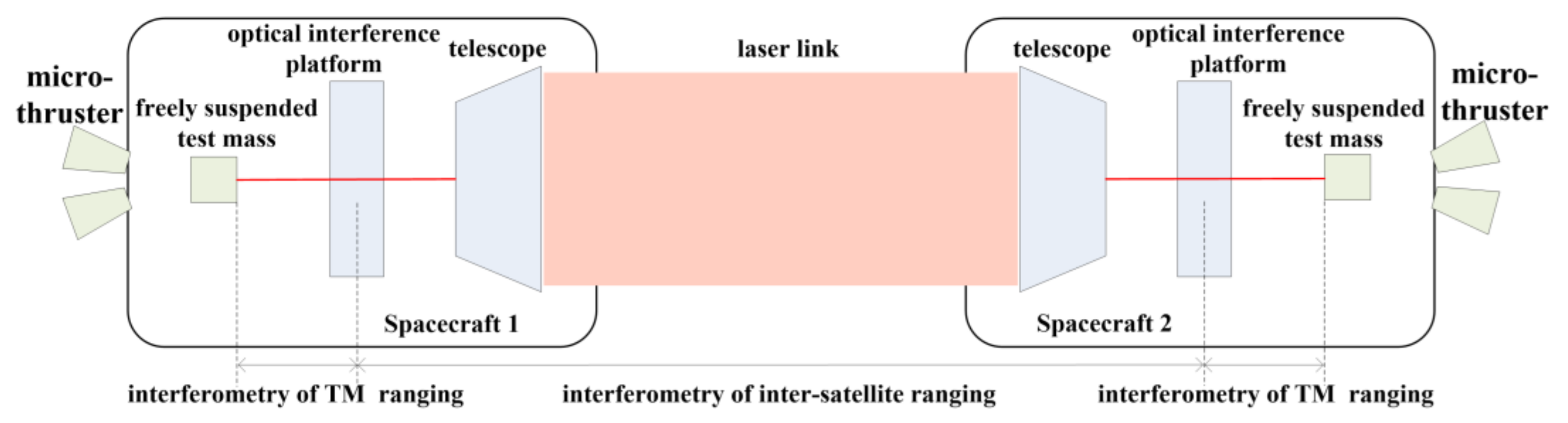
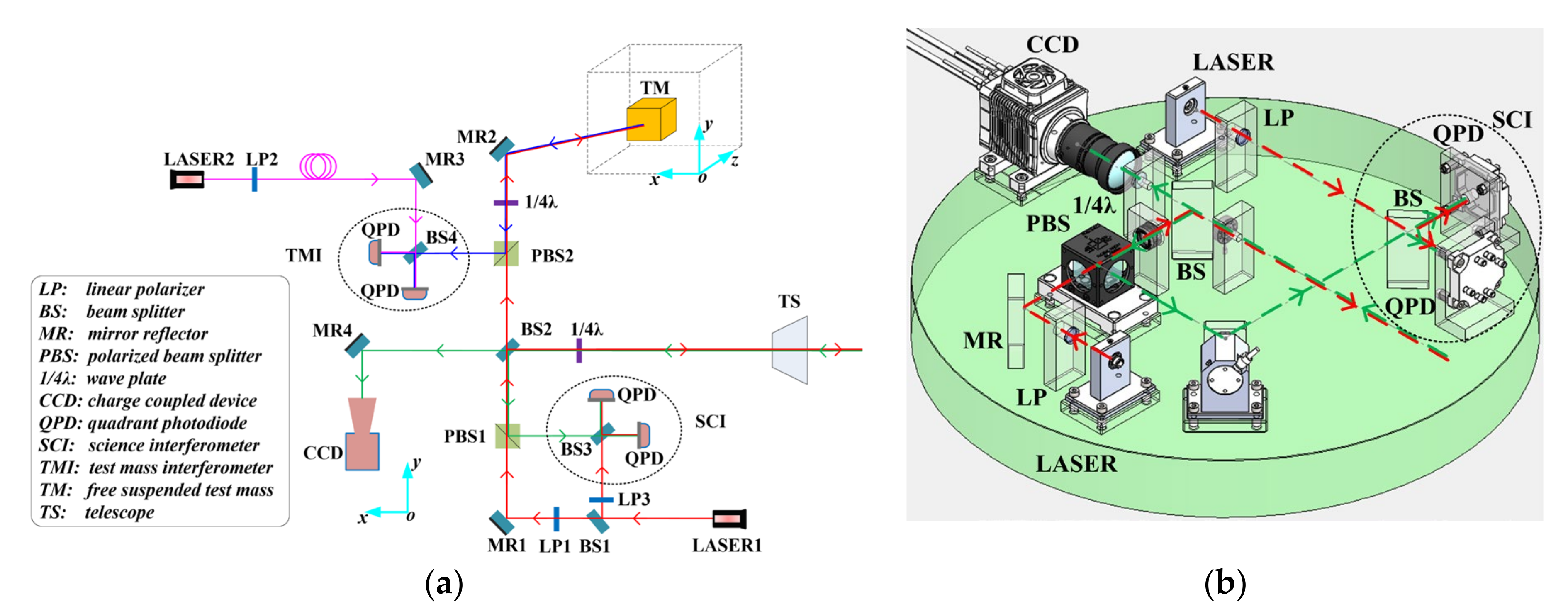
3.2. Semi-Physical Simulation Test for the Interferometry of Inter-Satellite Ranging

As mentioned earlier, distance fluctuations caused by gravitational waves between two freely suspended test masses, which are located in adjacent spacecrafts, are measured using laser interferometry. As shown in Figure 7, the optical interference platform is mounted on the spacecraft. Although space is a microgravity environment, tiny vibrations still exist on the spacecraft. Inside the spacecraft, vibrations are treated as common mode noise, which can be suppressed [29]. For the interferometry of inter-satellite ranging, vibrations are treated as differential mode noise, which cannot be eliminated; therefore, two freely suspended test masses are adopted as displacement reference benchmarks for the interferometry of space gravitational waves. The optical measurement process for distance fluctuations between two test masses is divided into three segments. One segment involves the interferometry of inter-satellite ranging between two optical interference platforms located in adjacent spacecrafts, while the other two segments involve the interferometry of TM (test mass) ranging between the optical interference platform and TM in each spacecraft.
The optical path design for the single-interference platform is depicted in Figure 8a. LASER1 (red line) is split into three parts by BS1 (beam splitter 1) and BS2. Two parts involve local laser beam 1, the first part of which is directly projected onto the center of the QPDs after splitting by BS3 of SCI. The second part is first transmitted to the TM. Both LPs (linear polarizers) and ¼λ wave plates are used to alter the polarization state of the laser. After passing through a ¼λ wave plate twice, the transmission direction of the laser through PBSs (polarized beam splitters) is changed. The laser beam (blue line) is reflected by the TM, MR2 (mirror reflector), and PBS2 in turn. Then, it is projected onto the center of the QPDs after splitting by BS4 of the TMI (test mass interferometer). The third part, which is split by BS2, is emitted out. LASER2 (pink line) is local laser beam 2 on the same platform. It is only projected onto the center of the TMI’s QPDs.
After being emitted by the remote spacecraft, the third part of LASER1 is received by the local interference platform. Then, the received laser beam (green line) is captured by the CCD and QPDs of SCI one-by-one.
With the interference of the first part of LASER1 and the received laser beam, the interferometry of inter-satellite ranging is achieved using SCI. Meanwhile, with the interference of the second part of LASER1 reflected by the TM and LASER2, the interferometry of TM ranging is achieved using TMI. As described in Section 3.1, the SCI is also used to carry out high-precision angle measurements using DWS technology at the same time. The 3D model of a single interference platform with only SCI is also shown in Figure 8b.
In order to achieve ranging noise of 100 pm/√Hz, a series of technical specifications are proposed for the parameters of the optical interference platform, telescope, and lasers, as listed in Table 5. To obtain the ideal interference effect, the two interfering beams need to be of equal height and parallel to each other; therefore, the degree of spot coincidence and included angle of the interfering beams are two parameters that need to be considered for the optical interference platform. Their corresponding technical specifications are guaranteed by the accuracy of the optical manufacturing and assembly processes. A joining technology named HCB (hydroxide-catalyzed bonding) is used in assembly of the optical interference platform. Optical components are bonded on a substrate made of zerodur. To ensure the scientific goals are achieved, high requirements are also placed on the telescope, including high wavefront quality, ultra-stable optical path stability, and extremely low stray light level. With a detailed design, high-precision optical manufacturing processes, and the use of an accurate alignment monitoring device, the corresponding technical specifications can be achieved. The frequency instability noise levels for LASER1 and LASER2 in Figure 8a are the major noise sources in laser interferometry, so high requirements are proposed for the laser frequency stability. These are met using the PDH (Pound–Drever–Hall) stabilization technique.
In the semi-physical simulation test for interferometry of the inter-satellite ranging, the real working conditions in space should be simulated; however, when the simulation is conducted on the ground, gravity and ground vibration noise are two factors that cannot be ignored.
Due to the existence of gravity, it is difficult to simulate a freely suspended test mass on the ground. According to previous studies [28,29,30,31,32,33,34], the specification test for interferometry ranging is conducted by measuring the system noise of the laser interference payload, in order to guarantee that the system noise is less than the specifications. The simulation of the freely suspended test mass is usually substituted by a fixed MR (mirror reflector) in a vacuum tank. As the common mode noise, the impact of the displacement fluctuation caused by various vibration noises on the interferometry ranging can be neglected. For the interferometry of inter-satellite ranging, two fixed MRs are needed. The noise caused by ground vibrations is differential mode noise. The relative displacement fluctuation between the two fixed MRs is much larger than the specifications, leading to test failure.
To perform a real semi-physical simulation test, two freely suspended test masses must be simulated while isolating disturbances from ground vibration noise to ensure that the relative motion between two test masses can be ignored. For this, multistage suspension technology is used [46,47,48,49], which was employed in LIGO. At the same time, an active control loop is imported. With the help of the millihertz-frequency and high-precision displacement sensor, the vibration noise in the low millihertz frequency band can be isolated through the active feedback control system. As a result, the freely suspended test mass can be simulated.
A schematic diagram and block diagram of the multi-stage suspension vibration isolation based on active control are shown in Figure 9. A two-stage suspension is used. An active control system, which is achieved by utilizing technologies such as an inertial sensor, PID control, weak force driver, and precision machinery, is imported on TM 1. The control period for the active control is far less than the period for the ground vibration; thus, the ground vibration noise is isolated by the active control acting on TM 1 before it is transmitted to TM 2 and suspended at the second stage. As such, TM 2 can move freely in the horizontal direction. Through reasonable design of the suspension system and active control system, the displacement disturbance of TM2 in the low millihertz frequency band can be ensured to be in the order of the pm magnitude, so as to perform the semi-physical simulation of the freely suspended test mass. This challenging task is currently being tackled by another participating team from the Taiji program.
The spacecraft simulation platform is also affected by the ground vibration noise. According to [50,51], ground vibration noise is caused by natural phenomena and human activities. There are two main types of noise: one is noise with a frequency range above 0.5 Hz, caused by the shake of buildings, trees, and human activities; the other type is noise with a frequency range of 0.05~0.5 Hz caused by surface waves and body waves in the crust, which are originated from collisions on the coast by sea waves. For the simulation of the micro-vibration environment of a spacecraft, a commercial precision active vibration isolation platform is used for effective isolation of ground vibration noise. The precision active vibration isolation platform needs to be placed horizontally on the desktop. From the analysis above, it can be seen that the spacecraft simulation platform must have the ability for both micro-vibration and high-resolution attitude adjustment; therefore, the spacecraft simulation platform is made up of the precision active vibration isolation platform and the piezo-driven hexapod described in Section 3.1, with the latter placed on the former. Based on these analyses, the TS150 [52], whose isolation frequency can be as low as 0.7 Hz, is selected.
The technical solution to the semi-physical simulation test for the interferometry of inter-satellite ranging is shown in Figure 10. Two test mass simulators, which are based on active suspension vibration isolation technology, are used to simulate the two freely suspended test masses in adjacent spacecrafts. The spacecraft simulation platforms, with the ability for both micro-vibration and high-resolution attitude adjustments, are used to simulate the spacecraft. The dual-spacecraft simulation platforms are placed between the two test mass simulators. Ranging noise of better than 100 pm/√Hz can be expected for the interferometry of inter-satellite ranging, which can be tested by measuring the system noise.

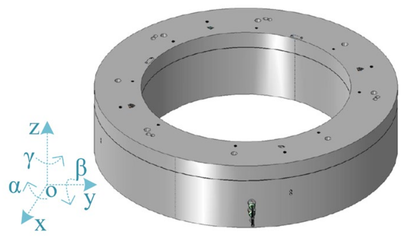
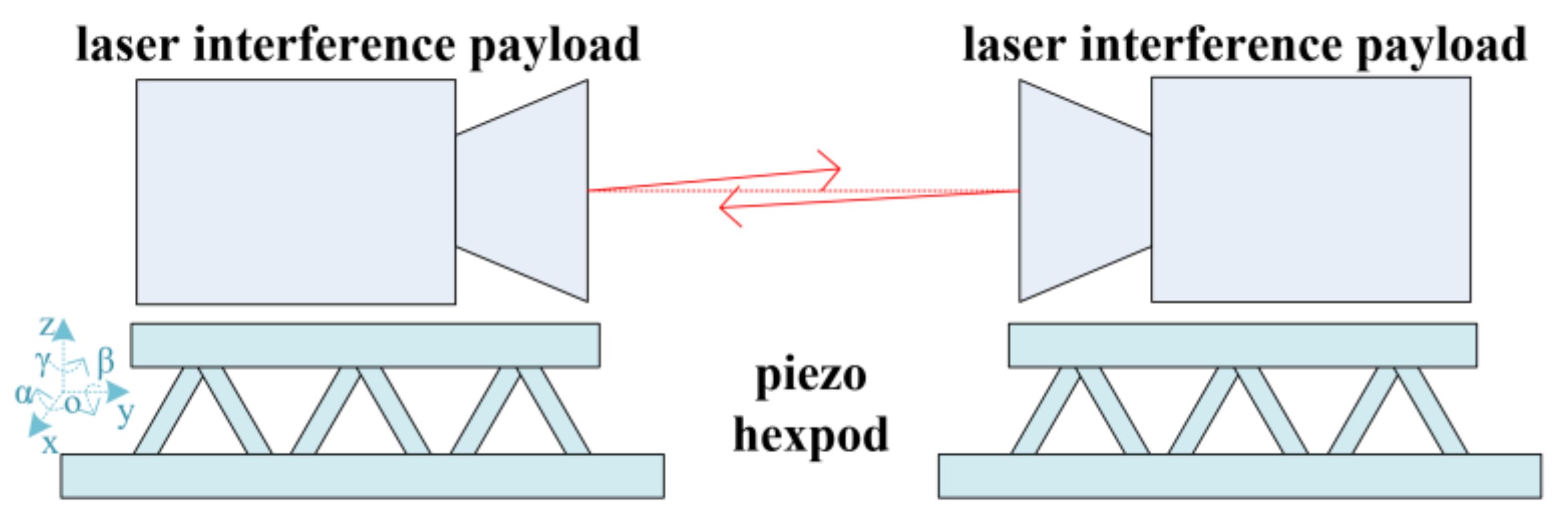
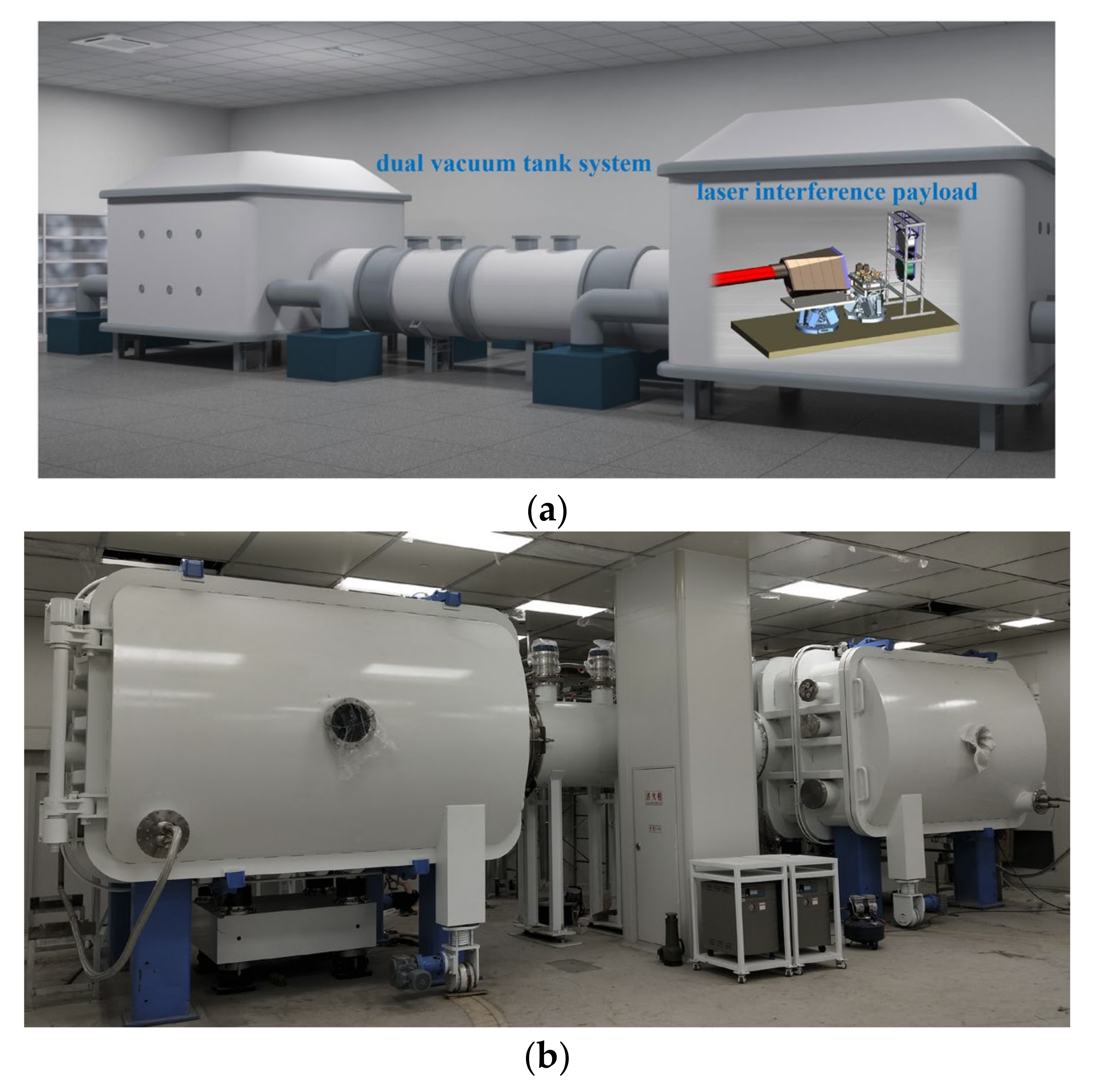
3.3. Semi-Physical Simulation of the Space Environment

When the semi-physical simulation is conducted on the ground, the temperature and pressure will influence the measurement results because of Rayleigh scattering, refractive index fluctuation, and optical element deformation [53,54]. To avoid these influences, a vacuum and cold-black space environment must be simulated in the semi-physical simulation test.
An oil-free vacuum tank with a heat sink, as shown in Figure 11, is adopted to simulate the cosmic vacuum and cold-black environment. The inner wall of the vacuum tank is blackened, with the heat sink surrounding the outside. The heat sink is filled with liquid nitrogen to obtain a uniform low temperature, which is used to simulate the cold-black space environment. The main technical parameters of the vacuum tank are listed in Table 6, which at a highly technical level can be achieved in the laboratory [55,56].
For the inter-satellite laser interference, simulation is required of the cosmic vacuum and cold-black environment where the two spacecrafts are located; therefore, the dual vacuum tank system shown in Figure 12 is used for the simulation. The dual vacuum tank system is composed of two vacuum tanks with a heat sink and a vacuum pipeline, the length of which is 10 m and which connect the two tanks. The inner diameter of the pipeline is 1 m, so as to ensure enough room to complete the laser acquisition reciprocally when establishing the inter-satellite laser link. An optical table is designed for each vacuum tank to carry the spacecraft simulation platform and the laser interference payload. According to Section 3.2, only ground vibration noise above 0.7 Hz can be isolated by the precision active vibration isolation platform. In order to minimize the impact of ground vibration noise on the laser interferometry, the optical table is also subjected to strict vibration isolation treatment. A two-stage vibration isolation method for the independent foundation plus active vibration isolation is adopted to ensure the vibration acceleration is attenuated to 10−5 g within the frequency range of 0.1~100 Hz.

4. Expected Results

Based on the detailed analyses of the semi-physical simulations described above, an experimental platform for the semi-physical simulation test of the inter-satellite laser interference is designed. The experimental scenario for the semi-physical simulation test of inter-satellite laser interference is shown in Figure 13a. The dual vacuum tank system under construction is depicted in Figure 13b.
With the combination of DWS technology and the piezo-driven hexapod, not only can the residual error of 1 μrad for the acquisition procedure based on the CCD be verified, but the test used to establish the inter-satellite laser link with a pointing jitter of 100 nrad/√Hz can also be performed. After establishing the stable laser link, the inter-satellite ranging interferometry test can be conducted by measuring the system noise. A ranging noise of better than 100 pm/√Hz can also be achieved.
Except for the semi-physical simulation test for the two key technologies, the semi-physical simulation demonstration of the in-orbit experiment processes can also be implemented using the experiment platform. These processes composed involve attitude control of the spacecraft, startup and shutdown of payloads, calibration of certain payloads, inter-satellite laser acquisition, weak-light phase locking, laser precision pointing, establishment of the laser link, execution of the scientific experiment mode, and other factors.
In the future, with the addition of the same vacuum tank with heat sink, the experimental platform can be upgraded to form a triangle, with which the semi-physical simulation test for the final triangle constellation of the Taiji program can also be performed.

5. Conclusions

As one of the most advanced science and technology processes in the world, space gravitational wave detection is extremely challenging. In order to guarantee the smooth implementation of the subsequent in-orbit mission, semi-physical simulation tests must be carried out on the ground before the payload is launched, in order to fully mitigate the technical risks. In this paper, a comprehensive and in-depth study is conducted, involving semi-physical simulation testing of the two key technologies (the establishment of the inter-satellite laser link and the inter-satellite ranging interferometry) involved in inter-satellite laser interference in the Taiji program. The research findings related to the semi-physical simulation of the space environment are also implemented.
Based on detailed analyses of semi-physical simulations, an experimental platform is designed. The simulation of the cosmic vacuum and cold-black environment is achieved using a dual vacuum tank system with an ultimate vacuum level as low as 5 × 10⁻⁶ Pa, temperature less than 80 K, and vibration acceleration attenuated to 10−5 g within the frequency range of 0.1~100 Hz. With the combination of DWS technology and the piezo-driven hexapod, not only can the residual error of 1 μrad for the acquisition procedure based on the CCD be verified, but the inter-satellite laser link with a pointing jitter of 100 nrad/√Hz can also be established. The interferometry testing of the inter-satellite ranging can be conducted by measuring the system noise. A ranging noise level of better than 100 pm/√Hz can also be achieved. The semi-physical simulation demonstration of the in-orbit experimental processes can also be performed using the experiment platform. The technical risks of the two key technologies involved in inter-satellite laser interference can be fully mitigated, laying a solid foundation for smooth implementation of gravitational wave detection in-orbit.
Further, the experimental platform can be upgraded to form a triangle. The semi-physical simulation test for the final triangle constellation of the Taiji program can also be performed.

Author Contributions

Conceptualization, Y.W. and J.W.; methodology, Y.N. and K.Q.; investigation, W.B.; writing—original draft preparation, X.X.; writing—review and editing, L.M.; funding acquisition, J.J., H.L., and Q.Y. All authors have read and agreed to the published version of the manuscript.

Funding

This research was funded by the Strategic Priority Research Program on Space Science, Chinese Academy of Sciences (grant numbers XDA1502110102, XDA1502110103), and the National Natural Science Foundation of China (Grant No. 61905268).

Institutional Review Board Statement

Not applicable.

Informed Consent Statement

Not applicable.

Data Availability Statement

Not applicable.

Acknowledgments

The authors thank Ziren Luo, a professor from the Institute of Mechanics, Chinese Academy of Sciences, for his helpful guidance on the technical solution.

Conflicts of Interest

The authors declare no conflict of interest.

References

  1. Einstein, A. Approximative Integration of the Field Equations of Gravitation. Sitzungsber. Preuss. Akad. Wiss. Berl. (Math. Phys.) 1916, 1916, 688–696. [Google Scholar]
  2. Harry, G.M.; LIGO Scientific Collaboration. Advanced LIGO: The next generation of gravitational wave detectors. Class. Quantum Grav. 2010, 27, 084006. [Google Scholar] [CrossRef]
  3. Abramovici, A.; Althouse, W.E.; Drever, R.W.P.; Gürsel, Y.; Kawamura, S.; Raab, F.J.; Shoemaker, D.; Sievers, L.; Spero, R.E.; Thorne, K.S.; et al. LIGO: The Laser Interferometer Gravitational-Wave Observatory. Science 1992, 256, 325–333. [Google Scholar] [CrossRef] [PubMed] [Green Version]
  4. Acernese, F.A.; Agathos, M.; Agatsuma, K.; Aisa, D.; Allemandou, N.; Allocca, A.; Amarni, J.; Astone, P.; Balestri, G.; Ballardin, G.; et al. Advanced Virgo: A second-generation interferometric gravitational wave de-tector. Class. Quantum Grav. 2014, 32, 024001. [Google Scholar] [CrossRef] [Green Version]
  5. Bradaschia, C.; Del Fabbro, R.; Di Virgilio, A.; Giazotto, A.; Kautzky, H.; Montelatici, V.; Passuello, D.; Brillet, A.; Cregut, O.; Hello, P.; et al. The VIRGO project: A wide band antenna for gravitational wave detec-tion. Nucl. Instrum. Methods Phys. Res. Sect. A Accel. Spectrom. Detect. Assoc. Equip. 1990, 289, 518–525. [Google Scholar] [CrossRef]
  6. Aso, Y.; Michimura, Y.; Somiya, K.; Ando, M.; Miyakawa, O.; Sekiguchi, T.; Tatsumi, D.; Yamamoto, H. Interferometer design of the KAGRA gravitational wave detector. Phys. Rev. D 2013, 88, 043007. [Google Scholar] [CrossRef] [Green Version]
  7. Akutsu, T.; Ando, M.; Arai, K.; Arai, Y.; Araki, S.; Araya, A.; Aritomi, N.; Asada, H.; Aso, Y.; Atsuta, S.; et al. KAGRA: 2.5 generation interferometric gravitational wave detector. arXiv 2019, arXiv:1811.08079. [Google Scholar] [CrossRef] [Green Version]
  8. Punturo, M.; Abernathy, M.; Acernese, F.; Allen, B.; Andersson, N.; Arun, K.; Barone, F.; Barr, B.; Barsuglia, M.; Beker, M.; et al. The Einstein Telescope: A third-generation gravitational wave observatory. Class. Quantum Gravity 2010, 27, 194002. [Google Scholar] [CrossRef]
  9. Sathyaprakash, B.; Abernathy, M.; Acernese, F.; Ajith, P.; Allen, B.; Seoane, P.A.; Andersson, N.; Aoudia, S.; Arun, K.; Astone, P.; et al. Scientific objectives of Einstein Telescope. Class. Quantum Gravity 2012, 29, 124013. [Google Scholar] [CrossRef]
  10. Wang, Y.Y. The third generation laser interferometer gravitational wave detector. Mod. Phys. 2017, 29, 39–51. [Google Scholar]
  11. Abbott, B.P.; Abbott, R.; Abbott, T.D.; Abernathy, M.R.; Acernese, F.; Ackley, K.; Adams, C.; Adams, T.; Addesso, P.; Adhikari, R.X.; et al. Observation of Gravitational Waves from a Binary Black Hole Merger. Phys. Rev. Lett. 2016, 116, 061102. [Google Scholar] [CrossRef] [PubMed]
  12. Prince, T.A. The Promise of Low-Frequency Gravitational Wave Astronomy; Astro2010: The Astronomy and Astrophysics Decadal Survey, Science White Papers. arXiv 2009, arXiv:0903.0103. [astro-ph.CO]. [Google Scholar]
  13. Jennrich, O.; Binétruy, P.; Colpi, M.; Danzmann, K.; Jetzer, P.; Lobo, A.; Nelemans, G.; Schutz, B.; Stebbins, R.; Sumner, T.; et al. NGO Assessment Study Report (Yellow Book). Cosmology and Extra-Galactic As-Trophysics. 2012. Available online: https://sci.esa.int/web/ngo/-/49839-ngo-assessment-study-report-yellow-book (accessed on 7 April 2021).
  14. Danzmann, K. LISA—An ESA cornerstone mission for the detection and observation of gravitational waves. Adv. Space Res. 2003, 32, 1233–1242. [Google Scholar] [CrossRef] [Green Version]
  15. Bender, P.; LISA Study Team. LISA. Laser Interferometer Space Antenna for the Detection and Observation of Gravitational Waves. Available online: https://pure.mpg.de/rest/items/item_52082/component/file_52083/content (accessed on 25 August 2021).
  16. Danzmann, K.; LISA study team. LISA: Laser interferometer space antenna for gravitational wave measurements. Class. Quantum Grav. 1996, 13, A247. [Google Scholar] [CrossRef] [Green Version]
  17. Luo, Z.; Guo, Z.; Jin, G.; Wu, Y.; Hu, W. A brief analysis to Taiji: Science and technology. Results Phys. 2020, 16, 102918. [Google Scholar] [CrossRef]
  18. Luo, Z.; Wang, Y.; Wu, Y.; Hu, W.; Jin, G. The Taiji program: A concise overview. Prog. Theor. Exp. Phys. 2021, 2021, 05A108. [Google Scholar] [CrossRef]
  19. Ziren, L.; Min, Z.; Gang, J.; Yueliang, W.; Wenrui, H. Introduction of Chinese Space-Borne Gravitational Wave Detection Program “Taiji” and “Taiji-1” Satellite Mission. J. Deep Space Explor. 2020, 7, 3–10. [Google Scholar] [CrossRef]
  20. Hu, W.-R.; Wu, Y.-L. The Taiji Program in Space for gravitational wave physics and the nature of gravity. Natl. Sci. Rev. 2017, 4, 685–686. [Google Scholar] [CrossRef]
  21. Jin, G. Program in space detection of gravitational wave in Chinese Academy of Sciences. J. Phys. Conf. Ser. 2017, 840, 12009. [Google Scholar] [CrossRef] [Green Version]
  22. Luo, J.; Chen, L.-S.; Duan, H.-Z.; Gong, Y.; Hu, S.; Ji, J.; Liu, Q.; Mei, J.; Milyukov, V.; Sazhin, M.; et al. TianQin: A space-borne gravitational wave detector. Class. Quantum Gravity 2016, 33, 035010. [Google Scholar] [CrossRef] [Green Version]
  23. Milyukov, V.K. TianQin Space-Based Gravitational Wave Detector: Key Technologies and Current State of Implementation. Astron. Rep. 2020, 64, 1067–1077. [Google Scholar] [CrossRef]
  24. Luo, J.; Bai, Y.-Z.; Cai, L.; Cao, B.; Chen, W.-M.; Chen, Y.; Cheng, D.-C.; Ding, Y.-W.; Duan, H.-Z.; Gou, X.; et al. The first round result from the TianQin-1 satellite. Class. Quantum Gravity 2020, 37, 185013. [Google Scholar] [CrossRef]
  25. Mei, J.; Bai, Y.-Z.; Bao, J.; Barausse, E.; Cai, L.; Canuto, E.; Cao, B.; Chen, W.-M.; Chen, Y.; Ding, Y.-W.; et al. The TianQin project: Current progress on science and technology. Prog. Theor. Exp. Phys. 2021, 2021, 05A107. [Google Scholar] [CrossRef]
  26. Danzmann, K. LISA mission overview. Adv. Space Res. 2000, 25, 1129–1136. [Google Scholar] [CrossRef]
  27. Nayak, K.R.; Dhurandhar, S.V.; Pai, A.; Vinet, J.-Y. Optimizing the directional sensitivity of LISA. Phys. Rev. D 2003, 68, 122001. [Google Scholar] [CrossRef]
  28. Schuldt, T.; Gohlke, M.; Weise, D.; Johann, U.; Peters, A.; Braxmaier, C. Compact laser interferometer for translation and tilt measurement as optical readout for the LISA inertial sensor. In Optomechatronic Sensors and Instrumentation III; International Society for Optics and Photonics: Bellingham, WA, USA, 2007; p. 67160F. [Google Scholar]
  29. Schuldt, T.; Gohlke, M.; Weise, D.; Johann, U.; Peters, A.; Braxmaier, C. Picometer and nanoradian optical heterodyne interferometry for translation and tilt metrology of the LISA gravitational reference sensor. Class. Quantum Gravity 2009, 26, 085008. [Google Scholar] [CrossRef]
  30. Dehne, M.; Tröbs, M.; Heinzel, G.; Danzmann, K. Verification of polarising optics for the LISA optical bench. Opt. Express 2012, 20, 27273–27287. [Google Scholar] [CrossRef]
  31. Heinzel, G.; Braxmaier, C.; Caldwell, M.; Danzmann, K.; Draaisma, F.; Garcia, A.; Hough, J.; Jennrich, O.; Johann, U.; Killow, C.; et al. Successful testing of the LISA Technology Package (LTP) interferometer engineering model. Class. Quantum Gravity 2005, 22, S149–S154. [Google Scholar] [CrossRef]
  32. Chwalla, M.; Danzmann, K.; Barranco, G.F.; Fitzsimons, E.; Gerberding, O.; Heinzel, G.; Killow, C.J.; Lieser, M.; Perreur-Lloyd, M.; Robertson, D.I.; et al. Design and construction of an optical test bed for LISA imaging systems and tilt-to-length coupling. Class. Quantum Gravity 2016, 33, 245015. [Google Scholar] [CrossRef] [Green Version]
  33. Lieser, M.; d’Arcio, L.; Barke, S.; Bogenstahl, J.; Diekmann, C.; Diepholz, I.; Fitzsimons, E.D.; Gerberding, O.; Henning, J.-S.; Hewitson, M.; et al. LISA Optical Bench Testbed. Available online: https://apc.u-paris.fr/~beckmann/Proceedings/Lieser.pdf (accessed on 25 August 2021).
  34. Tröbs, M.; D’Arcio, L.; Barke, S.; Bogenstahl, J. Testing the NGO/LISA optical bench. In Proceedings of the International Conference on Space Optics—ICSO 2012. SPIE 2019 Ajaccio, Corsica, France, 9–12 October 2012; Volume 10564, p. 1056440. [Google Scholar]
  35. Dong, Y.H. Inter-Satellite Interferometry: Fine Pointing and Weak-Light Phase-Locking Techniques for Space Gravitational Wave Observatory. Ph.D. Thesis, Institute of Mechanics, Chinese Academy of Sciences, Beijing, China, 2015. [Google Scholar]
  36. Li, Y.; Liu, H.; Zhao, Y.; Sha, W.; Wang, Z.; Luo, Z.; Jin, G. Demonstration of an Ultraprecise Optical Bench for the Taiji Space Gravitational Wave Detection Pathfinder Mission. Appl. Sci. 2019, 9, 2087. [Google Scholar] [CrossRef] [Green Version]
  37. Cirillo, F. Controller Design for the Acquisition Phase of the LISA Mission Using a Kalman Filter. Ph.D. Thesis, University of Pisa, Pisa, Italy, 2007. [Google Scholar]
  38. Zhang, L.; Dai, J.; Li, C.; Wu, J.; Jia, J.; Wang, J. Design and in-orbit test of a high accuracy pointing method in satellite-to-ground quantum communication. Opt. Express 2020, 28, 8291–8307. [Google Scholar] [CrossRef] [PubMed]
  39. Gao, R.H.; Liu, H.S.; Luo, Z.R.; Jin, G. Introduction of laser pointing scheme in the Taiji program. Chin. Opt. 2019, 12, 425–431. [Google Scholar]
  40. Gao, R.H.; Liu, H.S.; Luo, Z.R.; Jin, G. Linearity performance analysis of the differential wavefront sensing for the Taiji pro-gramme. J. Mod. Optic. 2020, 67, 383–393. [Google Scholar] [CrossRef] [Green Version]
  41. Yu, X.; Gillmer, S.R.; Ellis, J. Beam geometry, alignment, and wavefront aberration effects on interferometric differential wavefront sensing. Meas. Sci. Technol. 2015, 26, 125203. [Google Scholar] [CrossRef]
  42. Gao, R.; Liu, H.; Zhao, Y.; Luo, Z.; Shen, J.; Jin, G. Laser acquisition experimental demonstration for space gravitational wave detection missions. Opt. Express 2021, 29, 6368–6383. [Google Scholar] [CrossRef] [PubMed]
  43. Han, S.B. Solid State Physic Effects and Modern Transducer Technology. Piezoelectrics Acoustooptics 1997, 19, 235–236. [Google Scholar]
  44. Gao, R.H. The Research on the Laser Acquisition-Pointing Technique of Inter-Satellite Interferometer for the Space-Based Gravi-tational Wave Detection. Ph.D. Thesis, Institute of Mechanics, Chinese Academy of Sciences, Beijing, China, 2020. [Google Scholar]
  45. Piezo Positioning Systems with Parallel Kinematics. Available online: https://www.pi-china.cn/zh_cn/technology/parallel-kinematics/parallel-kinematics/ (accessed on 13 April 2021).
  46. Robertson, N.A.; Abbott, B.; Abbott, R.; Adhikari, R.; Allen, G.S.; Armandula, H.; Aston, S.M.; Baglino, A.; Barton, M.; Bland, B.; et al. Seismic isolation and suspension systems for Advanced LIGO. In Proceedings of the Gravitational Wave and Particle Astrophysics Detectors, Glasgow, UK, 21–25 June 2004; SPIE: Bellingham, WA, USA, 2004; Volume 5500, pp. 81–92. [Google Scholar]
  47. Hua, W.; Adhikari, R.; DeBra, D.B.; Giaime, J.A.; Hammond, G.D.; Hardham, C.; Hennessy, M.; How, J.P.; Lantz, B.T.; MacInnis, M.; et al. Low-frequency active vibration isolation for advanced LIGO. In Proceedings of the Gravitational Wave and Particle Astrophysics Detectors, Glasgow, UK, 21–25 June 2004; SPIE: Bellingham, WA, USA, 2004; Volume 5500, pp. 194–206. [Google Scholar]
  48. Matichard, F.; Lantz, B.; Mason, K.; Mittleman, R.; Abbott, B.; Abbott, S.; Allwine, E.; Barnum, S.; Birch, J.; Biscans, S.; et al. Advanced LIGO two-stage twelve-axis vibration isolation and positioning platform. Part 1: Design and production overview. Precis. Eng. 2015, 40, 273–286. [Google Scholar] [CrossRef] [Green Version]
  49. Matichard, F.; Lantz, B.; Mason, K.; Mittleman, R.; Abbott, B.; Abbott, S.; Allwine, E.; Barnum, S.; Birch, J.; Biscans, S.; et al. Advanced LIGO two-stage twelve-axis vibration isolation and positioning platform. Part 2: Experimental investigation and tests results. Precis. Eng. 2015, 40, 287–297. [Google Scholar] [CrossRef] [Green Version]
  50. Huang, W.; Huang, T.; Gao, M.; Guo, Y. Experimental Research of Some Interference Factors in the Development Process of Absolute Gravimeter. Open J. Nat. Sci. 2017, 5, 358–364. [Google Scholar] [CrossRef]
  51. Abbott, B.P.; Abbott, R.; Adhikari, R.; Ajith, P.; Allen, B.; Allen, G.; Giardina, K.D.; Arain, M.A.; Araya, M.; Armandula, H.; et al. Laser Interferometer Gravitational Wave Detector. Prog. Astron. 2014, 32, 351–353. [Google Scholar]
  52. TS Series DataSheet.Pdf. Available online: https://www.herzan.com/products/active-vibration-control/ts-series-upgrades.html (accessed on 28 May 2021).
  53. Feng, Y. Laser interferometer gravitational-wave detectors—Hearing aids for human on deep universe. Physics 2016, 45, 293–299. [Google Scholar]
  54. Li, L.; Wang, X. Current Status and Prospects for Thermal Effects on Optical Systems and Athermalisation Techniques. Opt. Technol. 1997, 5, 27–28. [Google Scholar]
  55. Wang, F.; Jing, J.-R.; Li, C.-L.; Qi, X.-J. Development of vacuum thermal environment test system for deep space detector. Vacuum 2019, 56, 16–20. [Google Scholar]
  56. Li, Y.-Q.; Jin, G. A brief overview of 8 m prototype facility of laser interferometer for Taiji pathfinder mission. Appl. Phys. B 2021, 127, 88. [Google Scholar] [CrossRef]
Figure 1. The Chinese Taiji program for space gravitational wave detection.
Applsci 11 07872 g001
Figure 2. Detection of space gravitational waves by laser interferometry (side view).
Applsci 11 07872 g002
Figure 3. Schematic diagram of the experimental platform for semi-physical simulations test of inter-satellite laser interference (side view).
Applsci 11 07872 g003
Figure 4. The two-stage acquisition strategy based on the CCD and QPD.
Applsci 11 07872 g004
Figure 5. The 3D model of the customized piezo-driven hexapod.
Applsci 11 07872 g005
Figure 6. Technical solution for the semi-physical simulation test for the establishment of inter-satellite laser links.
Applsci 11 07872 g006
Figure 7. Interferometry of ranging between two test masses (side view).
Applsci 11 07872 g007
Figure 8. Schematic diagram of single interference platform: (a) the optical path design; (b) the 3D model of a single interference platform with only SCI.
Applsci 11 07872 g008
Figure 9. Schematic diagram and block diagram of active suspension vibration isolation.
Applsci 11 07872 g009
Figure 10. Technical solution for the semi-physical simulation test for the interferometry of inter-satellite ranging.
Applsci 11 07872 g010
Figure 11. Schematic diagram of a vacuum tank with a heat sink (top view).
Applsci 11 07872 g011
Figure 12. Simulation of the space environment for the two spacecrafts using the dual vacuum tank system (top view).
Applsci 11 07872 g012
Figure 13. Experimental scenario for the semi-physical simulation test: (a) the experimental scenario; (b) the dual vacuum tank system under construction.
Applsci 11 07872 g013
Table 1. Main technical parameters involved in the acquisition procedures based on the CCD and QPD [28].
Acquisition ProceduresParametersTechnical Specifications
Based on CCDUncertainty area range ±23.9 μrad
Acquisition residual error1 μrad
Based on QPDFOV (field of view)1.5 μrad
Pointing jitter100 nrad/√Hz
Table 2. Main technical parameters of the SH640 camera.
ParametersTechnical Specifications
Number of pixels640 × 512
Pixel size15 μm
Focal length of imaging system150 mm
Photoelectric conversion efficiency (η)0.7 A/W @ 1064 nm
Table 3. Main parameters of the GD4542-20M QPD.
ParametersTechnical Specifications
Working wavelength1064 nm
Diameter of photosensitive surface1.2 mm
Interval between quadrant 40 μm
3 dB bandwidth20 MHz
NEP @20 MHz4.5 × 10−12 W/√Hz
Table 4. Specification requirements for the customized piezo-driven hexapod.
ParametersTechnical Specifications
Resolution in αβγ100 nrad
Travel range αβγbigger than ±23.9 μrad
Load50 kg
Table 5. Main parameters of the optical interference platform, telescope, and laser.
ComponentsParametersTechnical Specifications
Optical interference platformDegree of spot coincidence for the interfering beams<100 μm
Included angle of the interfering beams<100 μrad
TelescopeEffective aperture100 mm
Optical efficiency0.853
Magnification80×
Wavefront qualityλ/20 rms
Optical path stability50 pm/√Hz
Stray light1 × 10−6
LaserWavelength1064 nm
Frequency stability30 Hz/√Hz
Power20 mW
Table 6. Main technical parameters of the vacuum tank with a heat sink.
ParametersTechnical Specifications
Ultimate vacuum5 × 10−6 Pa
Leakage rate<1 × 10¹⁰ Pa·m3/s
Temperature<80 K
Temperature uniformity±3 K
Publisher’s Note: MDPI stays neutral with regard to jurisdictional claims in published maps and institutional affiliations.

