Abstract
We propose a unified theory for the metrological treatment of helical machine elements such as cylindrical and conical gears, worms, and screw threads. The main idea is to introduce a universal 3D geometry model for threaded components that provides for distinct parameterization using a unique set of geometry parameters and that offers and a functional description of the transverse profile. Using modern 3D coordinate measuring technology, a holistic evaluation algorithm yields the actual geometry as the result of a high dimensional best-fit procedure and form deviations as corresponding residuals. All determinants and evaluation parameters can then be calculated from the set of actual geometry parameters. By applying certain constraints to the model to be fitted, the novel method can be reduced to the established 2D methods and hence meets demands for the comparison of the two procedures. The results of the novel approach have proven to be very stable and they enable the evaluation of areal measurements with no loss of information.
1. Introduction
Gears and threads of all kinds are important elements in a broad variety of technical machinery. Their applications range from simple mechanical fasteners to key components found in all types of vehicles as well as in heavy-duty machinery and offshore energy systems. Whatever the scale, high-precision engineering is required to satisfy the narrow tolerances demanded in gear and thread production, tolerances that define the aims of manufacturing metrology. Current metrological challenges stemming from current trends in production technology can be summarized in five keywords: fast, accurate, reliable, flexible, and holistic [1].
Modern coordinate metrology systems are capable of gathering holistic information about the dimensions and surfaces of complex-shaped workpieces and can do so quickly, with high point density and with a good level of accuracy. However, standard evaluation procedures still reference single lines to represent the gear and thread geometry in the most relevant 2D sections. This is described for gears in the standards ISO 1328-1 [2] and AGMA 1012 [3], or in the corresponding VDI/VDE standards for profile and helix measurements [4] and pitch measurement [5]. The relevant definitions for threads can be found in ISO 5408 [6], ASME B1.1 [7], or DIN 2244 [8], while more specific measurement instructions for plugs and rings are described in VDI/VDA standards [9,10].
This has been the state of the art for many decades, and it may be sufficient for quality control as long as the production method complies with the workpiece’s kinematics and the manufacturing tolerances are not too tight. Beyond this, however, holistic evaluation procedures that assess the complete surface using one common model offer several advantages. Besides the obvious benefits of being able to determine deviations along the entire flank and of having sounder and more stable geometrical fitting parameters, holistic treatment allows us to find correlations between different measurands and to properly understand possible manufacturing errors. Moreover, modern production methods that do not follow the kinematic principles (such as five-axis milling) need holistic inspection for reliable quality assurance since line-based deviation analysis does not provide sufficient information on how to adjust machine tool parameter settings.
For involute gears, an elementary approach to 3D descriptions was presented in [11]. In 1996, Lotze [12] was the first to introduce a holistic 3D model of involute gears to be treated as regular and freeform geometries in modern coordinate measuring technology. Detailed mathematical formulas can be found in [13]. Independently, Goch proposed an alternative approach that also considered flank modifications [14,15]. An extension of this work, in which the residuals of the fitted flanks are approximated by Chebyshev polynomials, can be found in [16].
As concerns screw threads, Schädel [17] developed an areal measurement strategy and holistic evaluation procedure based on an algorithm for non-linear least-squares approximation by Sourlier [18]. This technique has recently been verified by comparison to the established three-wire method [19].
Based on previous work that introduced a dedicated involute gear coordinate system [20], which was used to describe measurements in double flank contact [21] as well as profile and helix measurements [22], this article presents a universal model for helical machine elements. Defining a general class of helical machine elements allows metrological methods to be standardized for both gears and screw threads, as well as for any other geometry having an arbitrary transverse profile helically wound about the workpiece axis. This approach is advantageous as it permits general measurement strategies and evaluation algorithms to be easily adapted to special cases via a functional description of the transverse profile. The novelty of our work is the merging of the above approaches, so that based on the developed generalized mathematical model for helical machine elements, an areal measurement strategy, and a holistic evaluation can be applied.
In Section 2 we review the current state of the art in gear metrology and thread metrology and urge a common approach for both. Section 3 provides the mathematical description of the helical machine element model by derivation from the theory of ruled generalized helicoids. The relations of the holistic 3D model to the traditional 2D line-based results are explained in Section 4. In particular, we show that 2D evaluation is merely a special case of the 3D method and provide explicit formulas for the calculation of the most prominent standardized parameters from the best-fit result. In Section 5 we illustrate the benefits of the holistic procedure by looking at examples of measurement results. Section 6 concludes the paper and offers a perspective view on future research topics.
2. State of the Art in Gear and Thread Metrology
Traditional gear and thread metrology refers to single-point and line measurements in selected cross-sections. While some modern applications also apply 3D inspection methods, e.g., for rapid prototyping [23], calibration laboratories still stick to the traditional approach. Involute cylindrical gears are best described in a transverse section, i.e., in a plane perpendicular to the gear axis. This is due to the kinematic principle of two gears with parallel axes where the line of contact lies in a common transverse plane. By contrast, screw threads of all types are invariably characterized in an axial section, i.e., in a plane that contains the thread axis. This has proven convenient since most geometric thread parameters can easily be described in axial sections.
Gears and threads can both be treated as special types of a more general class of helical machine elements. The geometrical similarities of the two types of parts are depicted in Table 1 in terms of their determinants.

Table 1.
Equivalents of the most relevant gear and thread determinants. The names and symbols are in accordance with ISO 21771:2007 and ISO 5408:2009, respectively [6,24].
Despite the obvious similarities, gears and threads are currently treated in two different worlds encompassing aspects of standardization, design, manufacturing, metrology, and more. The work of the International Organization for Standardization (ISO) is spread across more than 250 technical committees (TCs). Among them, at the very top of the list, is ISO/TC1 Screw threads, which is responsible for thread standardization, while ISO/TC60 Gears develops standards for all the different types of gears. All TCs list their official liaisons to other TCs within ISO. Apparently, there is no cross-talk between TC1 and TC60, even though these committees list liaisons to 23 and 8 other ISO/TCs, respectively [25]. A similar separation of activities can be observed in the national standardization bodies in Germany, the U.S., and other countries.
Gears are typically measured on 3D coordinate measuring machines (CMMs) either with or without a rotary table or on dedicated gear measuring instruments which can be viewed as special CMMs that correspond to a cylindrical coordinate system rather than a Cartesian. By contrast, screw thread measurements are for the most part performed on 1D length comparators or 2D contour measuring devices. The main reason for employing these different techniques lies in the fundamental contrast in the concepts of the reference diameter of a gear on the one hand and the pitch diameter of a thread on the other. The reference diameter in gear metrology is merely a theoretical quantity that is used to determine nominal measurement points and to compute certain evaluation results. In thread metrology, the pitch diameter is agreed to be the most important measurand, the actual value of which implicitly contains information on the other determinants, including the lead and the thread angle.
As the differences described here may be the result of historical developments rather than the inevitable consequence of technical barriers, the following subsections will briefly review the origins of the gear/thread divide.
2.1. Classical Involute Gear Metrology
Classical gear metrology is based on the mechanical measuring devices established prior to the advent of coordinate measuring technology (CMT) in the 1970s, a technology that kinematically imitated the gear’s rolling process. Although CMMs have been established in gear metrology for several decades now, the principles behind the specific measurement and evaluation strategies do not follow the fundamental ideas pursued in other CMT applications. The major issue in state-of-the-art gear metrology is that each single measurement line is evaluated in an individual reference coordinate system. As a consequence, correlations between the different measurands cannot be detected and errors in the manufacturing process may not be identified properly.
There is a strict separation of the three main gear inspection categories: profile deviations, helix deviations, and pitch deviations (Figure 1). This categorization can be considered a remnant from a past era when fully equipped gear inspection labs needed at least three separate mechanical machines: an involute (profile) checker, a lead (helix) checker, and a pitch checker.
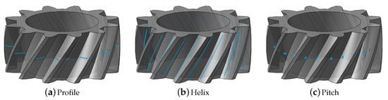
Figure 1.
Trinity in gear metrology. The classical line- and point-based gear measurements are divided into the three main categories profile, helix, and pitch.
The earliest mechanical generative involute measuring devices were designed to reproduce the base circle principle as the essential law in gear kinematics. They embodied a simple disc of the exact base circle diameter corresponding to the gear under test, and this disc was mounted to the spindle of the instrument. While the disc rotated around the spindle, a tangent ruler was pressed against it and slid along the gear profile. A measuring probe attached to this ruler would then directly record the deviations from the perfect involute, responding to either manufacturing errors or to misalignment of the gear against the disc. These deviations were written in real-time to a strip of paper moving in sync with the spindle’s rotation.
The mechanical lead checker followed the same approach. It used simple rotational and translational motions to rotate the gear and move the measuring probe in a way that emulated the exact lead of the part. Again, the probe directly measured the deviations from the nominal helix and wrote them onto a piece of moving chart paper.
For pitch measurements, a dedicated indexing machine was needed.
The resulting charts, which resembled seismographs or electrocardiograms, then needed to be read and interpreted. Since both the measurement and the output were completely analog, no numerical values were generated that could be used for calculations. Instead, the diagrams had to be evaluated by skilled technicians using rulers and triangles to determine slope and form deviations [26].
When gear metrology made the move to CNC machines like universal CMMs and specialized gear measuring instruments in the late 1970s, computations and the evaluation of standardized parameters were significantly facilitated. Despite this, the separation of measurement routines and determinants into a line-based profile and helix inspection on the one hand and pointwise pitch evaluation on the other has been preserved until today. Although only one machine is now needed for all three inspection tasks, the analysis of the results still does not allow the holistic description of manufacturing errors in one common coordinate system.
2.2. Classical Screw Thread Metrology
One of the most important pioneers in screw thread metrology was Prof. Georg Berndt (1880–1972) of the Technical University of Dresden in Germany. He was the first to describe the mathematics needed to determine the pitch diameter from tactile measurements in double-flank contact referred to as the three-wire method for plugs and the two-ball method for rings [27,28]. His algorithms for rake correction and compensation of probing element deformation were summarized and compared to other methods by Kochsiek and Lerch in 1974 [29], and this work formed the foundation for international calibration guide cg-10 published by EURAMET [30]. Though this guideline is still the most relevant international standard on the calibration of screw threads, it is limited to pitch diameter measurements of parallel threads. In other words, it does not cover other screw thread determinants like lead and flank angles nor can it be used for tapered threads.
State-of-the-art screw thread metrology relies on inspection in two axial sections that are perpendicular to each other. Reference [30] defines five categories of calibration that differ in the amount of cost and effort required and, as a consequence, in the quality and accuracy of the pitch diameter measurements. The idea is to measure only some of the quantities and assume the others to be nominal or at least within tolerance. When a thread gauge is calibrated for the first time, it is recommended to apply the most elaborate category with all determinants to be measured. However, even measurements from this category may prove to be prone to error, as seen in the results of a national intercomparison conducted in 2016/2017 with 20 participants [31]. This report lists 711 individual results, 110 of which indicated “unsatisfactory performance and generated an action signal” as described in ISO/IEC 17043:2010 [32].
Two weaknesses of the cg-10 measurement strategy are primarily responsible for the poor performance in comparison measurements. One relates to the sophisticated method of self-centering probing in double-flank contact. Although special artifacts have been designed for this type of probe characterization, the reproducibility is still much lower when compared to single-flank probing [33]. The second drawback obviously arises from the fact that the screw threads are only inspected in two axial sections. This means that errors in the roundness of the part may not be identified properly if the sections under assessment do not correspond to the angular sectors with maximum/minimum deviations. An example of this effect is given in Section 5 (Figures 6–8).
The two most relevant measurement strategies in established screw thread metrology are depicted in Figure 2.
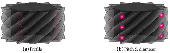
Figure 2.
Two of the most established strategies in screw thread metrology. The conventional line- and point-based measurements are divided into the categories of profile and combined pitch and diameter.
3. 3D Model of Helical Machine Elements
The basic idea in developing a common 3D model for a general class of helical machine elements is to describe the geometry in a transverse section (-plane) and then helically wind this geometry upwards about the z-axis. Each point of the transverse profile generates a helix and the complete profile curve gives a generalized helicoid. Actually, both the gears and the thread flanks are ruled generalized helicoids, i.e., surfaces that are generated by the screw motion of a straight line [11,34]. Additionally, some kinds of worm gear drives can be described in this way [35]. In the following, we briefly show the construction of the gear or thread flanks by this method.
Consider the line L in the -plane given by
This line is tangent to a cylinder around the z-axis with radius . By screw motion of L along the z-axis the surface
is generated (Figure 3).
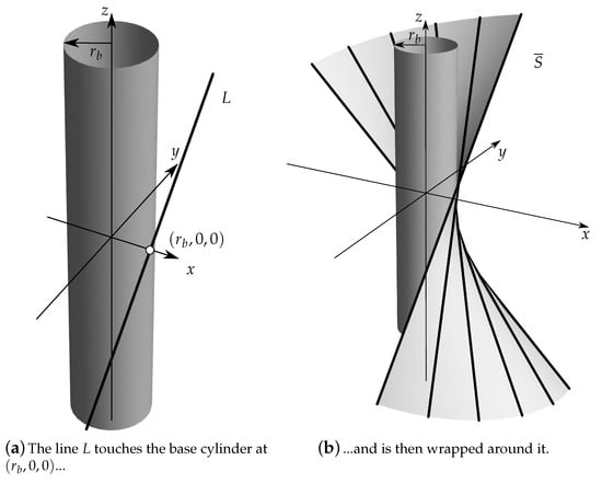
Figure 3.
The surface is generated by helically wrapping the line L around the base cylinder with the lead .
The parameter is called the helix coefficient. The direction of the rotation is given by the sign factor
Additionally, we introduce the starting polar angle of the generating line L at to allow a rotation around z of the complete surface. The parameters defining the surface are combined in the variable and Equation (2) reads as
The coordinates t and can mathematically take any value in . For technically feasible surfaces, however, restrictions on the coordinates will be necessary.
For practical applications in gear and thread metrology, it is more convenient to use the radius r instead of t as a coordinate. Since , this splits the surface into two flanks, depending on the sign of t. More precisely, let
with , where the additional minus sign is necessary to meet the conventions in gear metrology [20], as will become clear later.
This complements the set of geometry parameters uniquely defining the surface to
A single flank is hence given by
or
with . (For , is considered to be zero also for .)
Especially in gear metrology, where the transverse section of the flanks is often considered, the coordinate z is used rather than . Since
the flanks are then given by
where we introduced the transverse profile function
Equation (9) describes the surface of a flank as the screw motion of a curve on the -plane. While for generalized ruled helicoids the function is of the form given in Equation (10), one might of course consider more general functions leading to other surfaces.
Objects like gears or threads are constructed of left and right flanks for several teeth (or starts). In the case of gears, the definition
leads to results for the flanks which are consistent with the definitions in [20]. The same convention will be used in this paper in the case of screw threads. The construction of a thread from the two flanks is depicted in Figure 4. Note, however, that for other objects this definition of might not be suitable.
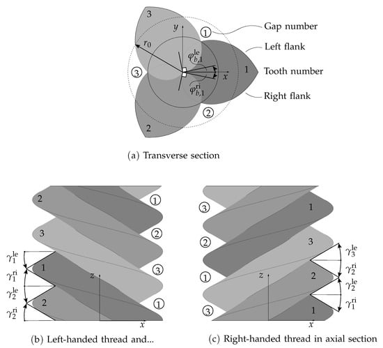
Figure 4.
Screw thread definitions.
If N is the number of teeth, we denote by
the parameters of the right flanks, and by
those of the left flanks. The corresponding flanks are denoted by and , respectively. For the nominal object, the values of and are typically the same for the left and right flanks and for all teeth. While there might be different values of , and , for the left and right flanks, these values are still the same for all teeth. The nominal values for satisfy
and accordingly for the left flanks. The values are specified by the desired position of the right and left flanks relative to each other. This can be defined via a reference circle in the -plane with a suitable radius with the condition that the arc length of the intersection of the reference circle with a tooth is . From Equation (10) it follows that this implies
The coordinate system is chosen such that the center point of the arc given by the intersection of the reference circle with the first tooth is equal to the point , hence
and
If , then , so is the angle of the point on the flank with radius in the plane . If , such an interpretation is not possible. In this case the direction of the intersection line of the flank with the plane at the point is given by
which is illustrated in Figure 4.
If the nominal values for c are the same for all flanks, the resulting objects are cylindrical. The case where the values for c differ for the left and right flanks is also of practical importance. Here, the radius where the tooth thickness takes the value is linearly dependent on z and the generated objects are conical. In this manner, (helical) beveloid gears [36] or tapered threads [6] can be constructed.
3.1. Involute Gears
Flanks of an involute gear are generated by a line tangent to the helix
with
through the point [37,38]. Here, denotes the base helix angle and the base circle radius of the gear [24]. This implies that
and hence from Equation (10) it follows that
where is the involute function and the transverse pressure angle [24]. The flank surface is thus
Note that in the case of gears the limit results in spur gears. However, the flanks are then of course no longer ruled generalized helicoids.
3.2. Screw Threads
In the case of a screw thread, the generating line (or its prolongation) has to intersect the z-axis, hence . Moreover, the slope m of the generating line is given by with the flank angle [6,8]. The definitions of left and right flanks are given in the transverse section (Figure 4a). Note that the relation to the corresponding flank angles depends on as illustrated in Figure 4b,c.
The function is then given by
i.e., the transverse section of the generated surface is an Archimedean spiral for or a straight line if . The equation for the flank surface finally reads
4. Relations to Standardized Measurands
The universal model established in Section 3 is used as a parametric representation of the form element to be fitted into a measured 3D point cloud by means of a sophisticated least squares algorithm [18]. This algorithm uses as fitting parameters not only the geometry parameters of the geometric element but also the orthogonal projections of the measurement points onto the surface of the geometric element. Moreover, the algorithm allows a separation of dimension, form, and position/orientation parameters, which makes it possible to determine the actual dimension and form deviations. The parameter vector for the fitting algorithm is an element of the high dimensional space , where n is the numbers of measurement points, g the number of geometry parameters, and l the position and orientation parameters. This allows a least-squares fit without an explicit representation of the residuals as a function of the geometry and position/orientation parameters.
In order to fulfill the requirements of holistic metrology, all geometry parameters defined in Section 3 have to be implemented into the best-fit procedure as free parameters. However, if certain geometry parameters are fixed to their nominal values, a comparison to the classical methods can be achieved. In the following subsections, we show how the geometry parameters from the 3D model relate to the measurands in established gear and thread metrology.
4.1. Gear Measurement
The most relevant measurands in gear metrology are described in ISO 1328:2013 [2]. For a single flank, the classical evaluation parameters and can be calculated by comparing the fitted parameters and to the nominal parameters and for a flank by
and
Here, is the reference length for the profile evaluation and b is the reference length for the helix evaluation. Moreover, the cumulative pitch deviations are given by
where and are the measured and nominal values, respectively, for , and denotes the reference circle radius of the gear. Illustrations and the derivation of Equations (27)–(29) can be found in [22].
The parameter m does not lead to another measurand since, in the case of gears, it is fixed by , and c.
In order to ensure the best comparability between the holistic evaluation and the classical method, certain parameters should be set to nominal values as specified in Table 2.
Table 2.
As classical gear metrology treats the three measurement categories (Figure 1) in different reference systems, the number of free geometry parameters should be reduced when the emphasis is on comparability.
4.2. Thread Measurements
For threads, the parameter is fixed by , so this parameter is not related to a measurand. The flank angles and for tooth i can be obtained from and by
The flank angles and for gap i as defined in ISO 5408:2009 [6] are then obtained according to the following table:
| hand | 1 | |
Here and in the following formulas in this section, a flank index value of 0 is understood as N. The thread angle for gap i is calculated with
The lead of a single right or left flank is further given by
The pitch diameter for gap i in the transverse section at position z is the diameter where the transverse gap width of gap i takes the value . It is given by
where must be chosen such that is in a reasonable range with respect to the nominal value. These z-dependent diameters form a cone with taper angle
Furthermore, the two-flank lead of gap i is given by
For cylindrical screw threads, the pitch between the flanks and i (right or left) measured at the nominal pitch radius is obtained with
with , where must be chosen such that is in a reasonable range with respect to the nominal value. The position z is the z-coordinate of the center of the two radially shifted points on the cylinder with radius between which the pitch is measured.
The general model derived in Section 3 constructs the screw thread geometry in the transverse section rather than in the axial section as is done in classical thread metrology. This motivates the definition of a transverse pitch for the left and right flanks by
From a production metrology point of view, the transverse pitch in Equation (37) is far more useful than the established axial pitch in Equation (36). Since the transverse pitch obviously relates to only one geometry parameter from the model, it is very clear how the machine settings have to be readjusted to compensate for a pitch error. In the case of the axial pitch, a deviation can account either for an incorrect helix coefficient c, a false flank angle represented by m, or a deviation in the rotational position of the flank in the transverse section denoted by . This separation of error sources is vital for reliable quality assurance and stems from the strict application of the coordinate metrology principle demanding the separation of dimension, form, and pose.
5. Some Examples
In this section, two examples are introduced to underpin the advantages of holistic and three-dimensional inspections. Two artifacts representing common helical machine elements were selected for this purpose: a single-start right-handed screw thread ring gauge and a right-handed involute cylindrical gear artifact with twelve teeth and certain flank modifications. The examples presented are intended to give a qualitative impression of the advantages of the areal measurement and evaluation approach rather than a quantitative comparison with the classical measurement strategy. For screw threads, such a comparison can be found in [19]. For involute gears, this is part of ongoing research and will be presented in a later publication.
In order to capture the surface of the parts, measurements were taken under laboratory conditions with temperature control on high-precision coordinate measuring machines equipped with integrated rotary tables with ball styli for tactile probing. To meet the definition of a holistic evaluation, the reference axis remained fixed during the measurements. For screw thread calibration, the surface was measured by scanning the flanks along the helix successively on varying radii. For gear calibration, additional profile scans were taken.
5.1. Screw Thread Ring Gauge
A screw thread ring gauge M (Figure 5) was calibrated applying the holistic approach presented in [39]. The part had previously been used in a national intercomparison among 20 calibration laboratories where it was measured in the conventional manner [31]. It was only through the application of the holistic calibration procedure that the dimension of a roundness deviation could be revealed for the first time.
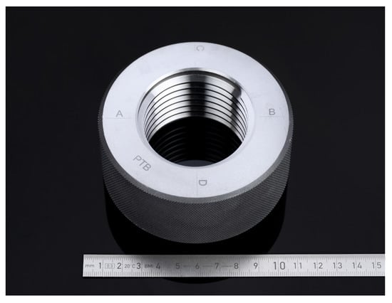
Figure 5.
Screw thread ring gauge M [39].
The applied measuring parameters for the calibration of the screw thread ring gauge with the holistic procedure are summarized in Table 3.
Table 3.
Measuring parameters of the screw thread ring gauge.
Figure 6 shows two screw thread flanks by means of determined residuals in a three-dimensional surface representation. The residuals were obtained by fitting form elements into a measured point cloud. Their values are represented by colors, with red denoting plus material and blue minus material. The gauge shows an ellipticity of up to . The reason for this deformation is unknown, but it might be a manufacturing error or a result of improper clamping in the past.
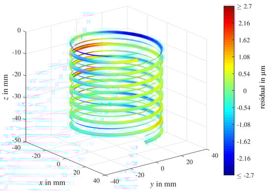
Figure 6.
Surface representation of residuals resulting from a screw thread fit [39].
Geometry deviations are easier to analyze if the flanks are unwound along the helix as presented in Figure 7. On the ordinate, residuals of the left-hand flank are shown in the same color scale as in Figure 6. The angle of unwinding and the radius are shown on the abscissae. The fluctuations over the angle correspond to a roundness deviation. The amplitudes indicate the maximum amount of deviation.
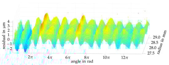
Figure 7.
Unwound residuals of a single screw thread flank [39].
As reported in Section 2.2, screw threads are conventionally inspected in two specific axial sections (A–B and C–D) in a pointwise or linewise manner. The pitch diameter (Equation (33)) determined with the holistic evaluation method (3D) is compared to conventional calibration results (2D) in Figure 8. Pitch diameters are shown with respect to the z-coordinate. Symbols represent the conventional 2D result. The sampling rate is not sufficient to capture the ellipticity. In contrast, the dimension of the ellipticity is clearly determined by the 3D method.
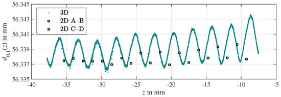
Figure 8.
Pitch diameter (curve) compared to conventional calibration results (symbols).
5.2. Involute Gear Artifact
Measurements were evaluated using the holistic method, for which areal measurements were performed on a gear artifact with twelve teeth and certain flank modifications (Figure 9). The nominal geometry parameters are summarized in Table 4 and the measuring parameters are listed in Table 5.
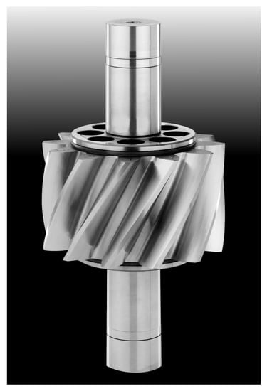
Figure 9.
Cylindrical involute gear artifact.
Table 4.
Nominal geometry parameters of the gear artifact.
Table 5.
Measuring parameters of the gear artifact.
The residuals are depicted on a color scale in Figure 10 at the locations of the fitted form elements, with red indicating plus material and blue minus material. Half of the teeth show significant form deviations resulting from flank modifications. In detail, they show either helix crowning, profile crowning, tip, root and end reliefs, or a combination of these. Figure 11 shows the unwound residuals of one specific gear flank with the z-coordinate and the roll angle on the abscissae.
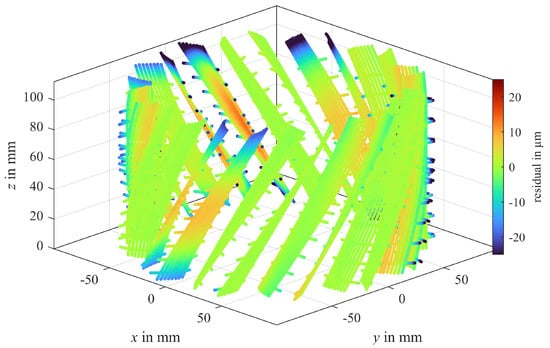
Figure 10.
Surface representation of residuals resulting from the holistic gear evaluation method.
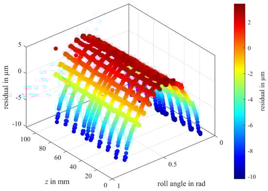
Figure 11.
Unwound residuals of a single gear flank (tooth 7, left flank).
The residuals indicate that this flank exhibits profile crowning. The parabolic shape is clearly visible following the application of the holistic evaluation method.
When it comes to pitch evaluation, the conventional strategy takes a single point at half face width at the reference diameter, see Figure 1c. The result would obviously be strongly affected by the maximum form deviation on this flank and therefore lead to a false assessment of the gear’s pitch.
In contrast, the holistic method determines the pitch based on all measuring points and calculates the mean position angle , which then leads to the cumulative pitch deviation according to Equation (29). This corresponds to a plane in Figure 11 at residual . As a consequence, the pitch assessment is far more stable, resulting in both smaller measurement uncertainties and in better linkage to machine parameter settings to allow proper failure analysis.
6. Conclusions and Outlook
A unified metrological approach has been presented which allows for a consistent treatment of involute spur, helical, and beveloid gears as well as of different kinds of worms and screw threads. It was possible to overcome the discrepancies between the classical gear and thread metrology methods by introducing a general model that describes helical machine elements of all sorts in their transverse profile. Given that the established thread determinants are defined in the axial and not in the transverse section, this approach led to a number of novel definitions, which are presented in Section 3.2. In Section 4, however, a small set of equations was introduced that are capable of describing the relation between the new unified model and the classical single approaches, thereby demonstrating that the new holistic theory is an extension of the traditional methods and showing how they correspond to one another.
The results from the examples presented in Section 5 show that the new 3D concept is superior to the established line-based measurements, as systematic errors from the manufacturing process can only be detected using the holistic method. Again, the correspondence of the results to those gathered with the conventional strategy can be seen as a verification of the novel approach (Figure 8).
The presented holistic method is based on the fundamental coordinate metrology principle of separation of features. This means that there is a clear distinction between parameters describing the measurement object in its dimension, form, and pose (i.e., position plus orientation). This is particularly beneficial when the workpiece coordinate system is to be defined by dedicated reference elements on the part, as is typical for running gears. In such cases, the six pose parameters can be removed from the best-fit procedure and set to the values determined by separate measurements.
In future work, the best-fit algorithms will be extended by minimum circumscribed and maximum inscribed elements that are needed for the exact characterization of screw threads and splines. For instance, the virtual pitch diameter of a screw thread is defined by a mechanical gauging process that can not be covered by Gaussian elements.
The evaluation algorithms will form the basis for a software test service to be included in the PTB’s online validation system, TraCIM [40] (https://tracim.ptb.de, accessed on 18 August 2021), in the near future.
Author Contributions
Conceptualization, M.S.; methodology, M.S., A.P. and F.K.; software, A.P. and F.K.; validation, M.S., A.P. and F.K.; writing—original draft preparation, M.S., A.P. and F.K.; writing—review and editing, M.S., A.P. and F.K.; visualization, A.P.; funding acquisition, M.S. All authors have read and agreed to the published version of the manuscript.
Funding
The 19ENG07 Met4Wind project has received funding from the EMPIR programme co-financed by the Participating States and from the European Union’s Horizon 2020 research and innovation programme.
Data Availability Statement
The data presented in this study are available on request from the corresponding author.
Acknowledgments
We acknowledge the support received from Marlen Krause, Sebastian Schädel, and Achim Wedmann, who conducted the measurements for the example results in Section 5.
Conflicts of Interest
The authors declare no conflict of interest. The funders had no role in the design of the study; in the collection, analyses, or interpretation of data; in the writing of the manuscript or in the decision to publish the results.
References
- Imkamp, D.; Berthold, J.; Heizmann, M.; Kniel, K.; Manske, E.; Peterek, M.; Schmitt, R.; Seidler, J.; Sommer, K.-D. Challenges and trends in manufacturing measurement technology—The “Industrie 4.0” concept. J. Sens. Sens. Syst. 2016, 5, 325–335. [Google Scholar] [CrossRef] [Green Version]
- ISO 1328-1:2013-09. Cylindrical Gears—ISO System of Flank Tolerance Classification—Part 1: Definitions and Allowable Values of Deviations Relevant to Flanks of Gear Teeth, 2nd ed.; International Organization for Standardization: Geneva, Switzerland, 2013. [Google Scholar]
- ANSI/AGMA 1012-G:2005 (R2011). American National Standard: Gear Nomenclature, Definitions of Terms with Symbols; American Gear Manufacturers Association: Alexandria, VA, USA, 2012. [Google Scholar]
- VDI/VDE 2612 Part 1:2018-11. Measurement and Testing of Gears–Evaluation of Profile and Helix Measurements on Cylindrical Gears with Involute Profile; Beuth Verlag GmbH: Berlin, Germany, 2018. [Google Scholar]
- VDI/VDE 2613:2003-12. Pitch and Runout Testing on Gearings—Cylindrical Gears, Whormwheels, Bevel Gears; Beuth Verlag GmbH: Berlin, Germany, 2003. [Google Scholar]
- ISO 5408:2009. Screw Threads—Vocabulary; International Organization for Standardization: Geneva, Switzerland, 2009. [Google Scholar]
- ASME B1.1:2019. Unified Inch Screw Threads (UN, UNR, and UNJ Thread Forms); The American Society of Mechanical Engineers: New York, NY, USA, 2019. [Google Scholar]
- DIN 2244:2002-05. Screw Threads—Terms and Screw Thread Elements for Parallel Screw Threads; Beuth Verlag GmbH: Berlin, Germany, 2002. [Google Scholar]
- VDI/VDE/DGQ 2618 Part 4.8:2006-04. Inspection of Measuring and Test Equipment—Setting Plugs, Plug Gauges and Test Plugs for Cylindrical Threads; Beuth Verlag GmbH: Berlin, Germany, 2006. [Google Scholar]
- VDI/VDE/DGQ 2618 Part 4.9:2006-04. Inspection of Measuring and Test Equipment—Test Instruction for Setting Rings and Ring Gauges for Cylindrical Threads; Beuth Verlag GmbH: Berlin, Germany, 2006. [Google Scholar]
- Härtig, F. Messtechnische Erfassung Polyevolventer Profile am Beispiel des Wälzfräsers. Ph.D. Thesis, Karlsruher Institut für Technologie (KIT), Karlsruhe, Germany, 1994. [Google Scholar]
- Lotze, W.; Rauth, H.-H.; Ertl, F. Neue Wege und Systeme für die wirtschaftliche 3D-Verzahnungsprüfung. VDI-Berichte 1996, 1230, 1021–1030. [Google Scholar]
- Lotze, W. Zahnradmessung mit Koordinatenmessgeräten; Eigenverlag: Dresden, Germany, 2005. [Google Scholar]
- Goch, G.; Guenther, A. Future Gear Metrology: Superficial Description and Inspection of Flanks. VDI-Berichte 2002, 1665, 751–768. [Google Scholar]
- Goch, G. Gear Metrology. CIRP Ann. Manuf. Technol. 2003, 52, 659–695. [Google Scholar] [CrossRef]
- Goch, G.; Ni, K.; Peng, Y.; Guenther, A. Future gear metrology based on areal measurements and improved holistic evaluations. CIRP Ann. Manuf. Technol. 2017, 66, 469–474. [Google Scholar] [CrossRef]
- Schädel, S.; Wedmann, A.; Stein, M. Advanced screw thread metrology using an areal measuring strategy and a holistic evaluation method. Meas. Sci. Technol. 2019, 30, 075009. [Google Scholar] [CrossRef]
- Sourlier, D. Three Dimensional Feature Independent Bestfit in Coordinate Metrology. Ph.D. Thesis, ETH Zürich, Zürich, Switzerland, 1995. [Google Scholar]
- Przyklenk, A.; Schädel, S.; Stein, M. Verification of a calibration method for 3D Screw Thread Metrology. Meas. Sci. Technol. 2021, 32, 094005. [Google Scholar] [CrossRef]
- Härtig, F.; Stein, M. 3D involute gear evaluation—Part I: Workpiece coordinates. Measurement 2019, 134, 569–573. [Google Scholar] [CrossRef]
- Stein, M.; Härtig, F. 3D involute gear evaluation—Supplement: Measurements in Double-Flank Contact. Measurement 2021, 176, 109079. [Google Scholar] [CrossRef]
- Stein, M.; Härtig, F. 3D involute gear evaluation–Part II: Deviations. Measurement 2021, submitted. [Google Scholar]
- Budzik, G.; Przeszlowski, Ł.; Wieczorowski, M.; Rzucidlo, A.; Gapinski, B.; Krolczyk, G. Analysis of 3D printing parameters of gears for hybrid manufacturing. AIP Conf. Proc. 2018, 1960, 140005. [Google Scholar]
- ISO 21771:2007-09. Gears–Cylindrical Involute Gears and Gear Pairs–Concepts and Geometry; International Organization for Standardization: Geneva, Switzerland, 2007. [Google Scholar]
- ISO—International Organization for Standardization. Available online: https://www.iso.org (accessed on 2 June 2021).
- Smith, D.; Pumm, C. The Convergence of Gear Metrology and 3-D Measuring Technology: The Slow Evolution. Gear Solut. Mag. 2015, 2, 45–49. [Google Scholar]
- Berndt, G. Die Gewinde: Ihre Entwicklung, Ihre Messung und Ihre Toleranzen; Springer: Berlin, Germany, 1925. [Google Scholar]
- Berndt, G. Die Anlagekorrekturen bei der Bestimmung des Flankendurchmessers von symmetrischen und unsymmetrischen Außen- und Innengewinden nach der Dreidrahtmethode oder mittels zweier Kugeln. Z. Instrum. 1940, 60, 141ff, 177ff, 209ff, 237ff, 272ff. [Google Scholar]
- Kochsiek, M.; Lerch, J. Zur Ermittlung von Bestimmungsgrößen an Gewinden; Physikalisch-Technische Bundesanstalt: Braunschweig, Germany, 1974. [Google Scholar]
- EURAMET cg-10 v2.1. Determination of Pitch Diameter of Parallel Thread Gauges by Mechanical Probing; The European Association of National Metrology Institutes: Braunschweig, Germany, 2012. [Google Scholar]
- Krause, M. Nationaler DKD-Ringvergleich für Gewindemessgrößen, Vergleichsbericht DKD-V4.3; Physikalisch-Technische Bundesanstalt: Braunschweig, Germany, 2017. [Google Scholar] [CrossRef]
- ISO/IEC 17043:2010. Conformity Assessment—General Requirements for Proficiency Testing; International Organization for Standardization: Geneva, Switzerland, 2010. [Google Scholar]
- Wedmann, A.; Kniel, K.; Krah, T.; Härtig, F. Accuracy enhancement for measurements in two-flank contact. tm Technisches Messen 2014, 81, 381–386. [Google Scholar] [CrossRef]
- Litvin, F.; Fuentes, A. Gear Geometry and Applied Theory, 2nd ed.; Cambridge University Press: Cambridge, UK, 2004. [Google Scholar]
- Dudás, I. The Theory and Practice of Worm Gear Drives; Penton Press: London, UK, 2000. [Google Scholar]
- Marino, D.; Binz, H.; Bachmann, M. Analytical design method for beveloid gears with a small shaft angle and offset. Forsch Ingenieurwes 2019, 83, 611–620. [Google Scholar] [CrossRef]
- Stachel, H. Comments on helical developables. In Proceedings of the 13th International Conference on Geometry and Graphics, Dresden, Germany, 4–9 August 2008. [Google Scholar]
- Linkeová, I.; Zelený, V. Application of ruled surfaces in freeform and gear metrology. Acta Polytechnica 2021, 61, 99–109. [Google Scholar] [CrossRef]
- Schädel, S. Rückführbare Messung und FläChenhafte Auswertung von Wendelförmigen 3D-Strukturen am Beispiel von Gewinden. Ph.D. Thesis, Technische Universität Ilmenau, Ilmenau, Germany, 2020. [Google Scholar]
- Wendt, K.; Franke, M.; Härtig, F. Validation of CMM evaluation software using TraCIM. Ser. Adv. Math. Appl. Sci. 2015, 86, 392–399. [Google Scholar]
Publisher’s Note: MDPI stays neutral with regard to jurisdictional claims in published maps and institutional affiliations. |
© 2021 by the authors. Licensee MDPI, Basel, Switzerland. This article is an open access article distributed under the terms and conditions of the Creative Commons Attribution (CC BY) license (https://creativecommons.org/licenses/by/4.0/).