Article

Feasible Energy Density Pushes of Li-Metal vs. Li-Ion Cells

by
Duygu Karabelli
1,* and
Kai Peter Birke
1,2
1
Fraunhofer Institute for Manufacturing Engineering and Automation IPA, Nobelstr. 12, 70569 Stuttgart, Germany
2
Chair for Electrical Energy Storage Systems, Institute for Photovoltaics, University of Stuttgart, Pfaffenwaldring 47, 70569 Stuttgart, Germany
*
Author to whom correspondence should be addressed.
Appl. Sci. 2021, 11(16), 7592; https://doi.org/10.3390/app11167592
Submission received: 16 July 2021 / Revised: 5 August 2021 / Accepted: 18 August 2021 / Published: 18 August 2021
(This article belongs to the Special Issue Chemistry for Lithium Metal Batteries)

Abstract

:
Li-metal batteries are attracting a lot of attention nowadays. However, they are merely an attempt to enhance energy densities by employing a negative Li-metal electrode. Usually, when a Li-metal cell is charged, a certain amount of sacrificial lithium must be added, because irreversible losses per cycle add up much more unfavourably compared to conventional Li-ion cells. When liquid electrolytes instead of solid ones are used, additional electrolyte must also be added because both the lithium of the positive electrode and the liquid electrolyte are consumed during each cycle. Solid electrolytes may present a clever solution to the issue of saving sacrificial lithium and electrolyte, but their additional intrinsic weight and volume must be considered. This poses the important question of if and how much energy density can be gained in realistic scenarios if a switch from Li-ion to rechargeable Li-metal cells is anticipated. This paper calculates various scenarios assuming typical losses per cycle and reveals future e-mobility as a potential application of Li-metal cells. The paper discusses the trade-off if, considering only the push for energy density, liquid electrolytes can become a feasible option in large Li-metal batteries vs. the solid-state approach. This also includes the important aspect of cost.

Graphical Abstract

1. Introduction

Existing conventional lithium-ion battery (LIB) technology is reaching its performance limits, as electric vehicle (EV) manufacturers aim to offer new EVs with extended driving range. To achieve this goal, the first approach was to increase nickel content in the cathode. However, the energy density of a battery does not only depend on the cathode but also the anode chemistry. Silicon based anodes are considered to be one of the most recent advances in Li-ion technology but they are also not expected to exceed energy densities of 800 Wh/L or 300 Wh/kg on a cell scale [1,2]. Therefore, the utilization of metallic lithium shows huge potential to meet the energy density requirements of future applications (up to 900 Wh/L) [3]. Li-metal has a specific capacity (3.860 mAh/g,) about ten times higher than that of graphite [4]. Although many studies used lithium metal (Li-metal) foils with a thickness of hundreds of microns in order to have a lithium reservoir against capacity loss, this approach is not practical for long-term developments [5,6]. The direct use of thick Li-metal foil will not only cause more rapid depletion of global lithium reserves and increase manufacturing costs, but will also bring some specific challenges associated with dendrite nucleation, limited coulombic efficiency (CE) and air and moisture sensitivity of the cell. Additionally, increasing the thickness of Li-metal foil (with excess lithium) decreases the volumetric capacity of lithium. For example, by a simple calculation, Genovese et al., have shown that if there is a 10 times excess of lithium (10×), the volumetric capacity decreases from 2060 mAh/L to 187 mAh/L, which is almost 4 times less than that of a graphite anode (719 mAh/L) [7]. Therefore, we should first of all define the term “excess” lithium clearly.
According to a study by Ahn et al. [8], it is suggested that maximum extraction of Li+ ions from an NMC 811 (LiNi0.8Mn0.1Co0.1O2) cathode was 0.5 and after this point a significant capacity fade was observed. For this reason, in this paper the extraction of Li+ ions will be assumed as 0.5. In this case, the delithiation reaction of NMC 811 can be given as following:
LiNi0.8Co0.1Mn0.1O2 → 0.5 Li + Li0.5Ni0.8Co0.1Mn0.1O2
According to the reaction above, the amount of Li of 0.5 will be released during charging and plate the current collector. When there is no additional Li-metal on the current collector, this layer will act as an anode (zero excess lithium).
Recently, anode-free (or zero-excess configuration) concepts have been proposed in many studies [3,7,9,10,11,12,13]. In this configuration, only a thin film current collector or surface modified current collectors are used as an anode (current collector), and the cathode material is the only lithium resource. During the first charge, lithium ions migrate from the cathode side to the negative current collector, are electrodeposited in situ on the current collector, and build a temporary Li-metal anode. Conversely, during discharge lithium ions move back into the cathode. The CE of such cells determines the reversibility of the cathode intercalation reaction and the cycle life since there is no extra Li source in the system. Moreover, from a safety point of view, since there isn’t any Li-metal foil for the cell preparation, a protected environment is not required during cell manufacturing. However, it is still challenging to establish a highly reversible in situ lithium electrodeposition & intercalation process. Tong et al. showed that an anode-free cell with 99.9% of CE presented a cycle life less than 400 cycles [13]. As an increase of CE is the major key to success, it is also important to conduct research with thin film lithium metal anodes. Therefore, it has been recommended to use lithium foils thinner than 50 µm and most ideally less than 30 µm [6,7,14].
CE or Faraday efficiency can be simply described as the proportion of the total charge extracted from the cell (Qdc) to the total charge put into the cell (Qc):
CE = Qdc/Qc
For conventional LIBs, it was observed that the CE increases with the first 15–20 cycling, after which a CE-value of more than 99.9% [15,16] can be reached. Here the question is what type of Li-metal battery cell design is required in order to achieve at least the same performance values of the current LIB technology? Within the scope of this article, we will discuss different Li-ion excesses, with different anode and cathode thicknesses to understand the effect of different numbers and parameters on the columbic efficiencies and the energy density. This paper aims to present various realistic scenarios in order to answer how much energy density can be gained by the technology transition from LIBs to Li-metal batteries (LMBs). For this aim, the paper is organized with the following sections:
  • Understanding the need for a Li-metal anode: Why do we need Li-metal instead of conventional graphite or silicon/graphite for anode active materials?
  • Excess lithium and energy density: How much lithium do we need in the cell in order to gain higher energy density and higher CE?
  • Thickness of the Li-metal anode: Does a thick Li-metal anode provide the best performance? What is the limit?
  • Achieving long cycle life and long driving distance range with a reasonable excess lithium: Different EV battery capacities and different energy consumption scenarios. What do these scenarios tell us?
  • Liquid electrolytes vs solid electrolytes for LMBs: As an option, the feasibility of liquid electrolytes will also be discussed if the increase of the energy density is considered as the main goal. At the end the cost aspect will also be reflected on.

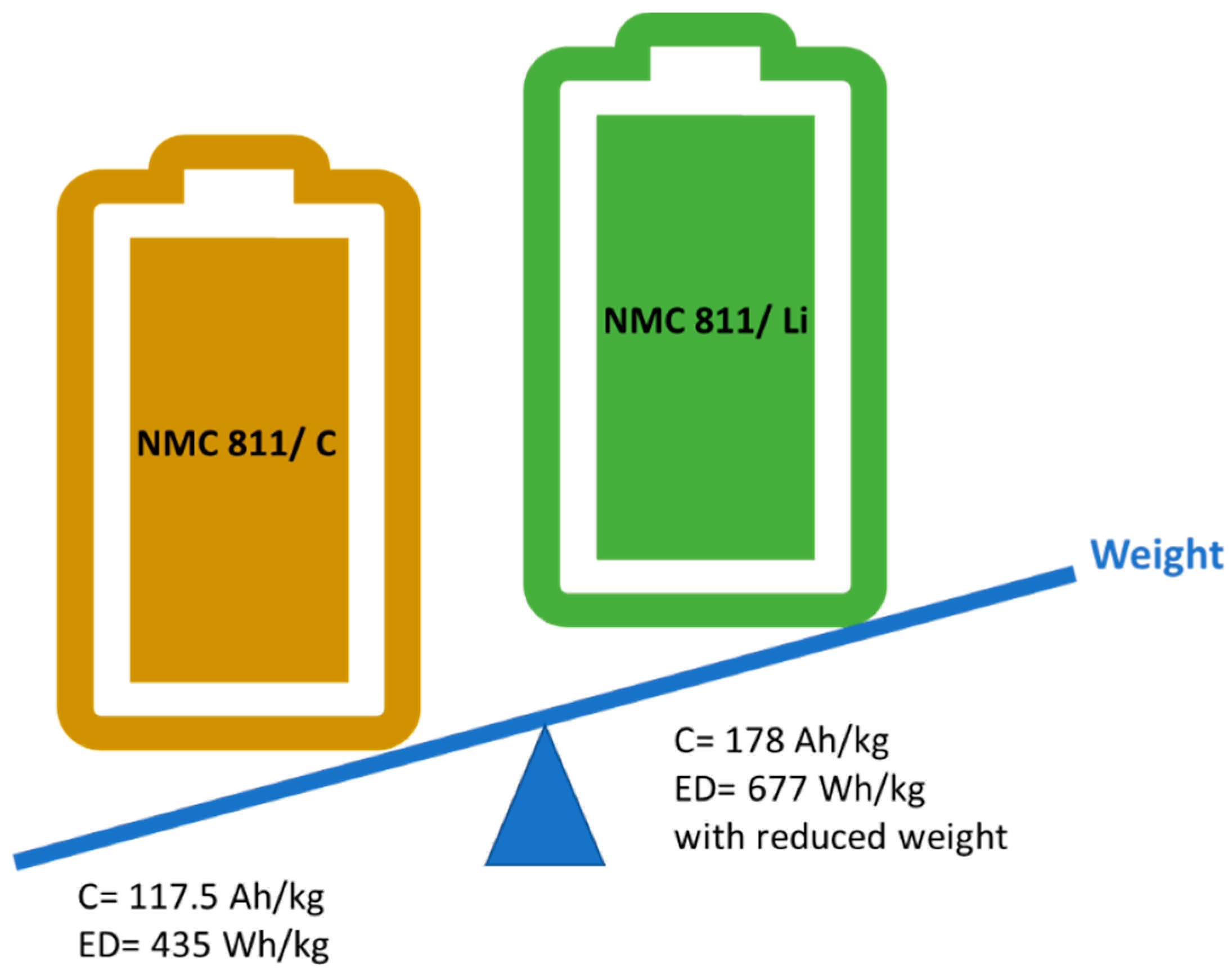
2. Understanding the Need for a Li-Metal Anode

The performance of the LIBs is determined by cathode, anode and electrolyte. However, as the anode materials provide much more specific capacity than the cathode materials, the overall cell capacity is limited by the cathode active material. For example NMC 811 (LiNi0.8Mn0.1Co0.1O2) offers 220 mAh/g of capacity where graphite and Li-metal offer 372 mAh/g and 3860 mAh/g of capacity, respectively [16]. An overview of the characteristics of different cathode and anode active materials are given in Table 1.
In order to meet the requirements of next generation battery systems for electromobility, the battery should provide an energy density of more than 300 Wh/kg at cell level to achieve a range of more than 600 km per charge. If we compare today’s high specific cathode material NMC 811 with graphite and Li-metal anode, we can see that according to capacity ratios (Ccathode/Canode), each gram of NMC 811 corresponds to either 0.6 g of graphite or 0.06 g of Li-metal (see Supplementary Materials). Assuming an extra 15% of weight is coming from other cell materials (separator, current collector and electrolyte) [16], theoretical capacity (C) and energy density (ED) of the cells can be calculated by the following equations:
C cell = C cathode Weight cathode +   Weight anode / ( 1.15 )
ED= Ccell × Vcell
As it is sketched in the Figure 1, using a high-capacity anode with lower redox potential results in high ED cells. The challenging point here is not only to achieve the highest ED but to keep this high ED in the cell for many cycles. For example, another high capacity silicon (Si) anode (4200 mAh/g) is hard to consider as a “next-generation” EV battery component, due to its volumetric expansion (up to 400%) during cycling [20]. In order to increase its cycle life, many approaches, such as using Si nano-wires and/or mixing Si with different ratios of graphite, were proposed [2,20,21,22,23].
As one of the biggest hurdles in the development of LIBs is the long charging time, other important criteria for material selection are the electrochemical and physical performances of the material at high C rates (>1C). The goal for future EVs is to reduce charging time to less than 15 min [24]. Nevertheless, charging the battery at higher rates accelerates battery degradation and capacity fading [24,25,26]. This capacity fading mainly occurs because of two different phenomena: (i) deposition of metallic lithium onto the graphite anode (Li-plating) [24,25,26] and (ii) failure/fracture of electrode particles due to diffusion-induced stresses [27,28,29]. For the first, as the deposition takes place in dendritic form, it leads to a safety risk through short circuits. Additionally, the volume expansion due to Li-plating deforms the stable solid electrolyte interphase (SEI) which protects liquid electrolyte decomposition [30]. For the second, Shim et al., showed that the charging & discharging process causes stress on the graphite anode [31]. This stress does not result only in volume changes and cracks in the anode structure but also in a slow diffusion of Li ions during the intercalation process. Undoubtedly, this second phenomenon tends to be more aggressive if the charging rate is increased.
Fast charging may also cause overheating of the liquid electrolyte, and these electrolytes can catch fire. Since all solid-state batteries (ASSBs) contains no liquid in the cell, this risk is eliminated and they can be charged at higher C-rates.
Last but not least, the cost of ASSBs is expected to be lower due to (i) use of less anode active material for higher capacity and ED, (ii) no need for sophisticated safety components (saving more space), and (iii) less production steps compared to LIBs (no electrolyte filling).
All points discussed above favor the utilization of Li-metal in the batteries instead of conventional graphite anodes. The crucial question of “how much Li-metal in the cell?” still remains not fully answered. The following sections will discuss this question, taking into account CE and cycle life of the battery through different scenarios.

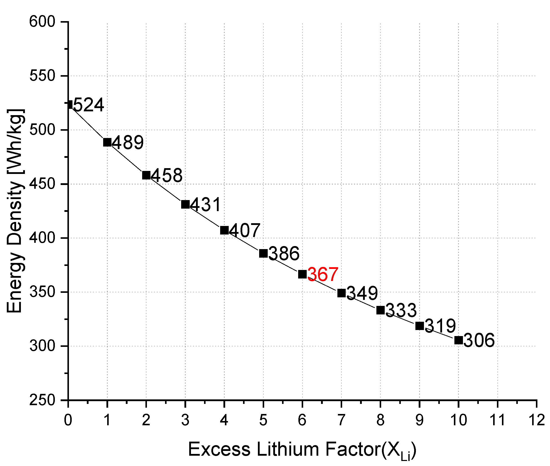
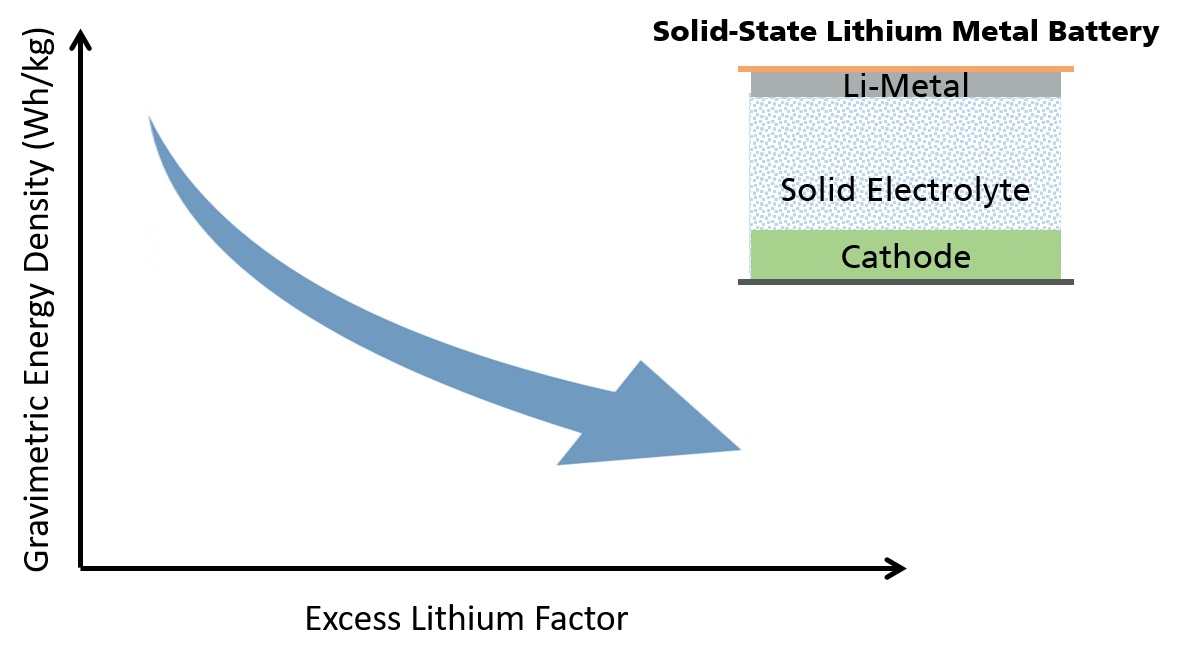
3. Excess Lithium and Energy Density

As a first approach, we will compare a Li-metal battery (LMB) cell and a LIB cell only from the point of view of the active materials. For this purpose, we start with the reaction equations between the cathode NMC 811 and a graphite anode and Li-metal anode. Here we assume 0.5 Li extraction from the cathode (see introduction). As a result, we obtain the following discharge reactions for two different anode materials:
LiNi0.8Co0.1Mn0.1O2 → 0.5 Li + Li0.5Ni0.8Co0.1Mn0.1O2 (Li-Metal)
C6 + 2 LiNi0.8Co0.1Mn0.1O2 → LiC6 + 2 Li0.5Ni0.8Co0.1Mn0.1O2 (Graphite)
The amount of charge (Q) is obtained by multiplying the electrons transported in relation to the equations (n), by the Faraday constant (F = 96,485 C/mol or 26,801 Ah/mol).
Specific capacity (Csp) of the cell and the ED can be calculated by the following equations:
C sp ( Ah / g ) = n × F Mw
ED   ( Wh / kg ) = ( Csp   ×   Vcell )   1000
It should be noted that the molecular weight (Mw) values correspond to the Mw of the discharge products as a whole.
Table 2 compares the zero-excess (anode-free) LMB and LIB according to the given discharge reactions 5 and 6. This theoretical capacity is difficult to obtain, because it is not feasible to recover the in-situ deposited Li-ions 100% from the anode due to formation of the SEI [32]. In order to overcome loss of Li, the excess amount of Li is introduced to the cell. Assuming that NMC 811 exhibits 2.2 mAh/cm2 of areal capacity [33], and combining it with a zero-excess anode, namely only a copper current collector, this cathode would deposit dense Li-metal layer with a volumetric capacity of 2061 mAh/cm3 (CLi*densityLi). Li et al., reported that zero-excess is defined as the initial lithium thickness at the anode and corresponds to the areal capacity of the anode [32]. In this case, when the NMC 811 cathode is delithiated, the thickness of the Li-metal would be 2.2 mAh/cm2: 2061 mAh/cm3 ≅ 10 µm. Hence, if we initially use 10 µm of Li-foil on the copper it corresponds to a one times excess of Li, 20 µm of Li-foil with two times the excess Li, and so on. As the thickness of Li-metal increases, the volumetric ED decreases which is one of the main reasons to limit thickness of the Li-metal anode. However, the following question should be answered: How much excess provides benefits? Depending on the excess factor (XLi) used to get a complete cell, one can calculate change in energy densities and bring these values into relation with LIBs in a very good approximation. The Figure 2 shows the maximum theoretical limit of the excess lithium in order not to obtain an ED lower than that of the cell with a graphite anode (423 Wh/kg). The calculations of the ED values for different excess amounts of lithium can be found in the Supplementary Materials.
In theory, if the XLi is less than 6, the ED of the cell will be already more than graphite-based LIBs. Every excess lithium factor after 6 will deliver less than 367 Wh/kg which represents the energy density value of current lithium ion batteries with graphite anode. In order to reach to maximum values of ED and a long cycle life, it is indispensable to create a cell with high CE [7,13,34]. The cycling stability and XLi correlation can be estimated from the following equation:
X Li × CE n = 1
where n is the cycle number and 1 refers to 100% consumption of the lithium. For example if we take 2 times excess lithium and obtain 98% of CE:
2 × 0.98 n = 1 n = ln 0.5 ln 0.98 = 34.3
After approximately 34 cycles the lithium excess is depleted. Then we can answer how much excess would be needed to reach 80% lithium consumption after 1000 cycles at this efficiency?
X Li × 0.98 1000 = 0.8 X Li = 0.8 0.98 1000 = 47.5 × 10 6  
Approximately 47 million of lithium excess is obtained where we need a maximum value of XLi = 6 to obtain an acceptable ED. If we take XLi = 6 in the last equation, 80% of lithium will be consumed after almost 100 cycles. All these calculations prove that only increasing the excess lithium is not enough to obtain long lasting cells. The correlation between CE and XLi for a cell with 1000 cycle life span is presented in Figure 3.
When we combine the results of Figure 2 and Figure 3, it can be assumed that an energy density of 367 Wh/kg and CE of 99.8% can achieve XLi = 6. Nevertheless, the capacity ratio of negative to positive electrode (N/P ratio) is another parameter in order to determine the full cell performance [35,36,37]. For example, N/P ratio is equal to zero for an anode-free (zero excess) configuration. The recommended N/P ratio range is between 1 and 1.2 for LIBs and between 0 and 1 for LMBs [37].

4. Thickness of the Li-Metal Anode

In further modeling, we can assume the specific thicknesses of the cathode to be 50 µm, 100 µm and 150 µm. Starting from reaction Equation (4), for each cathode we can calculate the ratio of anode thickness to cathode thickness using the following equation:
Anode   thickness Cathode   thickness = Mw Li d Li Mw NMC   811 d NMC   811
According to the reaction Equation (4), for XLi = 1 we need 2 times 0.6 Li:
Anode   thickness Cathode   thickness = 6.941 × 0.6   ( 6.941   g / mol ) 0.534   g / cm 3 97.2805   g / mol 2.2   g / cm 3   Anode   thickness Cathode   thickness = 0.47
The NMC 811 density of 2.2 g/cm3 is taken from the study by Laveda et al. [38]. Based on the calculated thickness ratio for XLi = 1, the thicknesses of the anode are obtained as 23.5, 47, and 70.5 µm for cathodes with thicknesses of 50 µm, 100 µm, and 150 µm, respectively. It has to be noted that these thickness values correspond to the thickness of the anode side including Li depostion during the discharge. If we assume that the lithium deposition occurs on the anode side homogenously, it will already create a layer with a thickness of between 8.8 and 26.5 µm (Table 3, column for XLi = 0). The needed metal foil thickness can then be calculated by subtracting this plating value from the total thickness. Table 3 represents the required Li-metal thicknesses for each scenario.

5. Achieving Long Cycle Life and Long Driving Distance Range with a Reasonable Excess Lithium

As EVs are the main drivers for battery technology developments, the most suitable use-case scenario can be created by using target driving ranges. In this section, a theoretical analysis of excess lithium factor is made by considering different EV battery capacities, different energy consumption, and driving cycles.
Considering different EVs and their battery sizes, three different average specific energy consumption rates can be assumed: 15 kWh/100 km, 20 kWh/100 km and 25 kWh/100 km. We have chosen three different battery sizes from the study of Sanguesa et al. [39]:
  • Peugeot e-208: 50 kWh
  • Audi e-tron: 95 kWh
  • Tesla Roaster: 200 kWh (outlook, future battery design)
End-of-life (EoL) driving distances of EVs range from 150,000 to 300,000 kms (from 8 to 15 years) [40]. The table below gives the theoretical required cycle numbers in order to achieve 150,000 and 300,000 kms with different EV battery capacities and different energy consumption scenarios.
As has been represented above, small batteries with higher energy needs per 100 km will require more cycles to achieve the target driving distance. Additionally, the EV batteries are already expected to reach between 1000 and 3000 cycles.
In Section 3 we have shown the correlation between the CE and the cycle number (Equation (8)). The amounts of excess lithium required for different cycles and different CE values are listed in the Supplementary Materials. An overview is presented below.
If we combine the results of Table 4 and Table 5, it is very clear that big capacity batteries offer the ideal EoL driving range with lower cycle numbers. These cycle numbers can be reduced even more by decreasing the energy consumption (kWh/100 km). It should be noted that this consumption increases linearly with the weight of the EV, which can be reduced by use of light weight batteries.

6. Liquid Electrolytes vs. Solid Electrolytes for LMBs

The first LMB was already based on a “Li-metal” anode combined with organic liquid electrolyte (LiPF6- propylene carbonate) [41]. However, the use of metallic lithium form coupled with an organic liquid electrolyte caused the dendrite formations which eventually led to an internal short circuit and thus to a thermal runaway since porous polymer-based separators do not provide a sufficient physical barrier to stop the spread of dendrites. In addition, the existing liquid electrolytes are toxic and flammable due to the fluorinated salt LiPF6 carbonate solvents respectively [19].
Li et al., studied various liquid electrolytes for Li-metal anodes, in order to give a comprehensive understanding of the liquid electrolyte/lithium-metal anode limitations. They have shown that the most common problems associated with low CE are issued by fragile solid electrolyte interphase (SEI) [32]. The typical inorganic components of SEI are Li2CO3, LiF, Li2O, and LiOH [42] and it has been shown that increasing the amount of LiF in the SEI structure passivates the SEI layer and helps to increase CE [43]. In order to obtain higher LiF species, it is important to have a liquid electrolyte composition with high donatable fluorine concentration (DFC) [32]. As a result, among liquid electrolytes, fluorinated electrolytes such as lithium bis(fluorosulfonyl)imide (LiFSI) in fluoroethylene carbonate (FEC) provide longer cycle life. However, their cost is higher than that of conventional LiPF6 in carbonate electrolytes.
The replacement of a liquid electrolyte with a solid electrolyte, which is also acting as a separator, would create an inert solid system that could solve the problems mentioned above. In addition, solid-state batteries do not have a liquid junction, which facilitates the formation of series-connected cells in a pack, and the absence of this junction eliminates unnecessary volume, resulting in higher volumetric energy densities. Typically, organic liquid electrolytes for commercialized Li-ion batteries show conductivities of about 2 × 10⁻² S/cm at room temperature and this value is slightly decreased to 5 × 10⁻³ S/cm with the integration of common porous polyolefin separators [44]. As a result, solid electrolytes have to compete with at least these high ionic conductivity values.
After inorganic solid electrolytes, crystalline sulfide electrolytes such as Li10GeP2 S12 (LGPS) and argyrodite-type crystallines such as Li6PS5X (X = Cl, Br, I) (LPS) are the most popular with their ionic conductivity of 1.9 × 10⁻³ S/cm and 6.8 × 10⁻³ S/cm, (X = Cl and Br, respectively [45,46]. However, unlike the polymer electrolytes, they do not have flexible structure and are expensive (~LGPS: 695$/10 g) [19].
Solid polymer electrolytes can be processed more easily than crystalline sulfide electrolytes thanks to their softness. This flexibility provides low-cost production. Nevertheless, they suffer from good ionic conductivities at room temperature and the requirement of high operational temperature limits their use in EV applications.
In order to overcome many challenges related to SEI, dendrite formation, and low ionic conductivity, “solid” composite electrolytes may be the alternative solution. The reduced contact area of the liquid electrolyte part with a lithium metal anode can be benefitted by preparation of gel polymer electrolytes. Gel polymer electrolytes are prepared with a low crystalline polymer such as poly(vinylidene fluoride)-co-hexafluoropropylene (PVdF-HFP) and an organic liquid electrolyte such as LiPF6 in EC-DMC) in the polymer matrix. Despite their good ionic conductivities (up to 6 × 10⁻³ S/cm) [47], they suffer from lower mechanical properties and electrode compatibilities [48]. The addition of crystalline sulfide electrolytes to the composition would solve the low mechanical characteristics of the resulting electrolyte.

7. Summary

A significant improvement in the energy density of rechargeable lithium batteries is needed to meet future requirements, especially for e-mobility. In order to design a high-technology battery it is important to understand the limitations of both current and next-generation battery systems.
The energy density of a battery is mainly limited by two elements of a battery cell: the cathode and anode materials. Cell performances can be significantly enhanced through the selection and matching of electrode materials. Conventional Li-ion batteries are accepted as a very mature technology, however they are far behind future breakthroughs.
Even though there are associated technical challenges with Li-metal anodes, they are still regarded as key elements for next generation battery systems due to their high capacity and fast charging compatibility. Many studies have increased the energy density of lab-scale Li-metal batteries simply by using a thick Li-metal foil as an anode material. Although utilizing large amount of excess lithium appears to be a straightforward solution, it is clear that it cannot be a practical solution in the long term.
Within the scope of this paper, we have described basic parameters such as Coulombic efficiency, excess lithium, and cycle life for Li-metal anodes. It is clear that limited excess lithium brings higher energy density but unfortunately for a reduced number of cycles.
From this perspective, one can ask the key question: Do the next generation Li-metal batteries have to completely replace conventional ones? Or is there a compromise? The last section of this paper demonstrates clearly that Li-metal anodes can be an attractive material for large capacity batteries (>100 kWh) since significantly lower cycles are required for the EoL driving distance. These lower cycle numbers enable a Li-metal battery design with a feasible CE. Lower capacity batteries (<100 kWh) can still use conventional LIBs.
It should be noted that use of excess liquid electrolyte in LMBs may be an option to extend the life of the cells. However, in our experience, only those amounts of excess electrolyte which can be physically bound in the separator and the positive electrode are a good option, this electrolyte excess is at most around 10–20%. However, compared to LIB cells, about 25–30% of electrolyte can be subtracted, since the graphite anode does not exist and bare Li-metal cannot absorb any electrolyte. Recalculation for the entire cell means that although excess electrolyte can be applied, assuming the CE is high enough, there is an additional gain in gravimetric energy density of around 10–20% because electrolyte can be saved. In fact, this will increase rather than decrease the energy density of true lithium metal cells. If a liquid electrolyte is replaced by a solid electrolyte the gravimetric energy density decreases about 5–10% since solid electrolytes are heavier than liquid electrolytes.
Last but not least, it is very challenging to develop a battery technology with high energy density and low manufacturing cost at the same time. Cost reduction may be achieved by choosing non-critical raw materials, new cell design and easy manufacturing processes. At the moment, however, there is no mass production of Li-metal and/or solid-state cells, and as a result the costs are disproportionately high. Additionally, use of thin Li-metal foil will increase the cell cost as cells with thinner electrodes are more expensive to manufacture due to difficulties in the processability [49]. Therefore, anode-free (zero-excess) cell configuration and obtaining Li metal on the anode side through in situ Li deposition may be a promising cell design. This type of cell will both save on the cost of thin Li-metal foil and the cost of the manufacturing process as there won’t be a need for an expensive gas protected environment or a clean room.
To conclude, the variety in the battery market may allow for cost reduction, easier and different recycling strategies, and more sustainability.

Supplementary Materials

The following are available online at www.mdpi.com/article/10.3390/app11167592/s1.

Author Contributions

D.K.: Literature research, conceptualization, methodology, calculations, writing—original draft preparation; K.P.B.: conceptualization, methodology, validation, resources, supervision, writing—reviewing and editing. Both authors have read and agreed to the published version of the manuscript.

Funding

This research received no external funding.

Institutional Review Board Statement

Not applicable.

Informed Consent Statement

Not applicable.

Data Availability Statement

The data presented in this study are available as a Supplementary Materials.

Conflicts of Interest

The authors declare no conflict of interest.

References

  1. Xiang, H.; Zhang, K.; Ji, G.; Lee, J.Y.; Zou, C.; Chen, X.; Wu, J. Graphene/nanosized silicon composites for lithium battery anodes with improved cycling stability. Carbon 2011, 49, 1787–1796. [Google Scholar] [CrossRef]
  2. Chakrapani, V.; Rusli, F.; Filler, M.A.; Kohl, P.A. Silicon nanowire anode: Improved battery life with capacity-limited cycling. J. Power Sources 2012, 205, 433–438. [Google Scholar] [CrossRef]
  3. Lee, Y.-G.; Fujiki, S.; Jung, C.; Suzuki, N.; Yashiro, N.; Omoda, R.; Ko, D.-S.; Shiratsuchi, T.; Sugimoto, T.; Ryu, S.; et al. High-energy long-cycling all-solid-state lithium metal batteries enabled by silver–carbon composite anodes. Nat. Energy 2020, 5, 299–308. [Google Scholar] [CrossRef]
  4. Liu, B.; Zhang, J.-G.; Xu, W. Advancing Lithium Metal Batteries. Joule 2018, 2, 833–845. [Google Scholar] [CrossRef] [Green Version]
  5. Zhang, Y.; Zuo, T.-T.; Popovic, J.; Lim, K.; Yin, Y.-X.; Maier, J.; Guo, Y.-G. Towards better Li metal anodes: Challenges and strategies. Mater. Today 2020, 33, 56–74. [Google Scholar] [CrossRef]
  6. Louli, A.J.; Coon, M.; Genovese, M.; Degooyer, J.; Eldesoky, A.; Dahn, J.R. Optimizing Cycling Conditions for Anode-Free Lithium Metal Cells. J. Electrochem. Soc. 2021, 168, 020515. [Google Scholar] [CrossRef]
  7. Genovese, M.; Louli, A.; Weber, R.; Hames, S.; Dahn, J.R. Measuring the Coulombic Efficiency of Lithium Metal Cycling in Anode-Free Lithium Metal Batteries. J. Electrochem. Soc. 2018, 165, A3321. [Google Scholar] [CrossRef]
  8. Ahn, Y.-K.; Jo, Y.N.; Cho, W.; Yu, J.-S.; Kim, K.J. Mechanism of Capacity Fading in the LiNi0.8Co0.1Mn0.1O2 Cathode Material for Lithium-Ion Batteries. Energies 2019, 12, 1638. [Google Scholar] [CrossRef] [Green Version]
  9. Louli, A.J.; Genovese, M.; Weber, R.; Hames, S.G.; Logan, E.R.; Dahn, J.R. Exploring the Impact of Mechanical Pressure on the Performance of Anode-Free Lithium Metal Cells. J. Electrochem. Soc. 2019, 166, A1291. [Google Scholar] [CrossRef]
  10. Nanda, S.; Gupta, A.; Manthiram, A. Anode-Free Full Cells: A Pathway to High-Energy Density Lithium-Metal Batteries. Adv. Energy Mater. 2021, 11, 2000804. [Google Scholar] [CrossRef]
  11. Pande, V.; Viswanathan, V. Computational Screening of Current Collectors for Enabling Anode-Free Lithium Metal Batteries. ACS Energy Lett. 2019, 4, 2952–2959. [Google Scholar] [CrossRef] [Green Version]
  12. Weber, R.; Genovese, M.; Louli, A.J.; Hames, S.; Martin, C.; Hill, I.; Dahn, J.R. Long cycle life and dendrite-free lithium morphology in anode-free lithium pouch cells enabled by a dual-salt liquid electrolyte. Nat. Energy 2019, 4, 683–689. [Google Scholar] [CrossRef]
  13. Tong, Z.; Bazri, B.; Hu, S.-F.; Liu, R.-S. Interfacial chemistry in anode-free batteries: Challenges and strategies. J. Mater. Chem. A 2021, 9, 7396–7406. [Google Scholar] [CrossRef]
  14. Chai, J.; Chen, B.; Xian, F.; Wang, P.; Du, H.; Zhang, J.; Liu, Z.; Zhang, H.; Dong, S.; Zhou, X.; et al. Dendrite-Free Lithium Deposition via Flexible-Rigid Coupling Composite Network for LiNi0.5 Mn1.5 O4 /Li Metal Batteries. Small 2018, 14, e1802244. [Google Scholar] [CrossRef] [PubMed]
  15. Stevens, D.A.; Ying, R.Y.; Fathi, R.; Reimers, J.N.; Harlow, J.E.; Dahn, J.R. Using High Precision Coulometry Measurements to Compare the Degradation Mechanisms of NMC/LMO and NMC-Only Automotive Scale Pouch Cells. J. Electrochem. Soc. 2014, 161, A1364. [Google Scholar] [CrossRef]
  16. Miao, Y.; Hynan, P.; Von Jouanne, A.; Yokochi, A. Current Li-Ion Battery Technologies in Electric Vehicles and Opportunities for Advancements. Energies 2019, 12, 1074. [Google Scholar] [CrossRef] [Green Version]
  17. Mao, C.; Wood, M.; David, L.; An, S.J.; Sheng, Y.; Du, Z.; Meyer, H.M.; Ruther, R.E.; Wood, D.L. Selecting the Best Graphite for Long-Life, High-Energy Li-Ion Batteries. J. Electrochem. Soc. 2018, 165, A1837. [Google Scholar] [CrossRef]
  18. Andre, D.; Kim, S.-J.; Lamp, P.; Lux, S.F.; Maglia, F.; Paschos, O.; Stiaszny, B. Future generations of cathode materials: An automotive industry perspective. J. Mater. Chem. A 2015, 3, 6709–6732. [Google Scholar] [CrossRef]
  19. Karabelli, D.; Birke, K.; Weeber, M. A Performance and Cost Overview of Selected Solid-State Electrolytes: Race between Polymer Electrolytes and Inorganic Sulfide Electrolytes. Batteries 2021, 7, 18. [Google Scholar] [CrossRef]
  20. Dash, R.; Pannala, S. RETRACTED ARTICLE: Theoretical Limits of Energy Density in Silicon-Carbon Composite Anode Based Lithium Ion Batteries. Sci. Rep. 2016, 6, 27449. [Google Scholar] [CrossRef]
  21. Ashuri, M.; He, Q.; Shaw, L.L. Silicon as a potential anode material for Li-ion batteries: Where size, geometry and structure matter. Nanoscale 2016, 8, 74–103. [Google Scholar] [CrossRef] [PubMed]
  22. Andersen, H.F.; Foss, C.E.L.; Voje, J.; Tronstad, R.; Mokkelbost, T.; Vullum, P.E.; Ulvestad, A.; Kirkengen, M.; Mæhlen, J.P. Silicon-Carbon composite anodes from industrial battery grade silicon. Sci. Rep. 2019, 9, 14814. [Google Scholar] [CrossRef] [PubMed] [Green Version]
  23. Wang, J.; Li, S.; Zhao, Y.; Shi, J.; Lv, L.; Wang, H.; Zhang, Z.; Feng, W. The influence of different Si: C ratios on the electrochemical performance of silicon/carbon layered film anodes for lithium-ion batteries. RSC Adv. 2018, 8, 6660–6666. [Google Scholar] [CrossRef] [Green Version]
  24. Liu, Y.; Zhu, Y.; Cui, Y. Challenges and opportunities towards fast-charging battery materials. Nat. Energy 2019, 4, 540–550. [Google Scholar] [CrossRef]
  25. Tomaszewska, A.; Chu, Z.; Feng, X.; O’Kane, S.; Liu, X.; Chen, J.; Ji, C.; Endler, E.; Li, R.; Liu, L.; et al. Lithium-ion battery fast charging: A review. eTransportation 2019, 1, 100011. [Google Scholar] [CrossRef]
  26. Zhang, S.S. Identifying rate limitation and a guide to design of fast-charging Li-ion battery. InfoMat 2020, 2, 942–949. [Google Scholar] [CrossRef] [Green Version]
  27. Christensen, J.; Newman, J. A Mathematical Model of Stress Generation and Fracture in Lithium Manganese Oxide. J. Electrochem. Soc. 2006, 153, A1019. [Google Scholar] [CrossRef]
  28. Zhou, W. Effects of external mechanical loading on stress generation during lithiation in Li-ion battery electrodes. Electrochim. Acta 2015, 185, 28–33. [Google Scholar] [CrossRef] [Green Version]
  29. Zhou, W.; Hao, F.; Fang, D. The effects of elastic stiffening on the evolution of the stress field within a spherical electrode particle of lithium-ion batteries. Int. J. Appl. Mech. 2013, 5, 1350040. [Google Scholar] [CrossRef]
  30. Tian, Y.; An, Y.; Wei, C.; Jiang, H.; Xiong, S.; Feng, J.; Qian, Y. Recently advances and perspectives of anode-free rechargeable batteries. Nano Energy 2020, 78, 105344. [Google Scholar] [CrossRef]
  31. Shim, J.; A Striebel, K.A. The dependence of natural graphite anode performance on electrode density. J. Power Sources 2004, 130, 247–253. [Google Scholar] [CrossRef] [Green Version]
  32. Li, S.; Jiang, M.; Xie, Y.; Xu, H.; Jia, J.; Li, J. Developing High-Performance Lithium Metal Anode in Liquid Electrolytes: Challenges and Progress. Adv. Mater. 2018, 30, e1706375. [Google Scholar] [CrossRef]
  33. Mao, C.; Ruther, R.E.; Li, J.; Du, Z.; Belharouak, I. Identifying the limiting electrode in lithium ion batteries for extreme fast charging. Electrochem. Commun. 2018, 97, 37–41. [Google Scholar] [CrossRef]
  34. Adams, B.D.; Zheng, J.; Ren, X.; Xu, W.; Zhang, J. Accurate Determination of Coulombic Efficiency for Lithium Metal Anodes and Lithium Metal Batteries. Adv. Energy Mater. 2018, 8, 1702097. [Google Scholar] [CrossRef]
  35. Kim, C.-S.; Jeong, K.-M.; Kim, K.; Yi, C.-W. Effects of Capacity Ratios between Anode and Cathode on Electrochemical Properties for Lithium Polymer Batteries. Electrochim. Acta 2015, 155, 431–436. [Google Scholar] [CrossRef]
  36. Niu, C.; Pan, H.; Xu, W.; Xiao, J.; Zhang, J.-G.; Luo, L.; Wang, C.; Mei, D.; Meng, J.; Wang, X.; et al. Self-smoothing anode for achieving high-energy lithium metal batteries under realistic conditions. Nat. Nanotechnol. 2019, 14, 594–601. [Google Scholar] [CrossRef]
  37. Wu, X.; Song, K.; Zhang, X.; Hu, N.; Li, L.; Li, W.; Zhang, L.; Zhang, H. Safety Issues in Lithium Ion Batteries: Materials and Cell Design. Front. Energy Res. 2019, 7, 65. [Google Scholar] [CrossRef] [Green Version]
  38. Vidal Laveda, J.; Low, J.E.; Pagani, F.; Stilp, E.; Dilger, S.; Baran, V.; Heere, M.; Battaglia, C. Stabilizing Capacity Retention in NMC811/Graphite Full Cells via TMSPi Electrolyte Additives. ACS Appl. Energy Mater. 2019, 2, 7036–7044. [Google Scholar] [CrossRef]
  39. Sanguesa, J.A.; Torres-Sanz, V.; Garrido, P.; Martinez, F.J.; Marquez-Barja, J.M. A Review on Electric Vehicles: Technologies and Challenges. Smart Cities 2021, 4, 372–404. [Google Scholar] [CrossRef]
  40. Upadhyayula, V.K.; Parvatker, A.G.; Baroth, A.; Shanmugam, K. Lightweighting and electrification strategies for improving environmental performance of passenger cars in India by 2030: A critical perspective based on life cycle assessment. J. Clean. Prod. 2019, 209, 1604–1613. [Google Scholar] [CrossRef]
  41. Whittingham, M.S. Electrical Energy Storage and Intercalation Chemistry. Science 1976, 192, 1126–1127. [Google Scholar] [CrossRef]
  42. Zhang, S.; Liu, Y.; Liu, H. Understanding lithium transport in SEI films: A nonequilibrium molecular dynamics simulation. Mol. Simul. 2020, 46, 573–580. [Google Scholar] [CrossRef]
  43. Suo, L.; Xue, W.; Gobet, M.; Greenbaum, S.G.; Wang, C.; Chen, Y.; Yang, W.; Li, Y.; Li, J. Fluorine-donating electrolytes enable highly reversible 5-V-class Li metal batteries. Proc. Natl. Acad. Sci. USA 2018, 115, 1156–1161. [Google Scholar] [CrossRef] [Green Version]
  44. Lagadec, M.F.; Zahn, R.; Wood, V. Characterization and performance evaluation of lithium-ion battery separators. Nat. Energy 2019, 4, 16–25. [Google Scholar] [CrossRef] [Green Version]
  45. Cao, C.; Li, Z.-B.; Wang, X.-L.; Zhao, X.-B.; Han, W.-Q. Recent Advances in Inorganic Solid Electrolytes for Lithium Batteries. Front. Energy Res. 2014, 2, 25. [Google Scholar] [CrossRef] [Green Version]
  46. Rao, R.P.; Adams, S. Studies of lithium argyrodite solid electrolytes for all-solid-state batteries. Phys. Status Solidi A 2011, 208, 1804–1807. [Google Scholar] [CrossRef]
  47. TechVision Group. Innovations in Solid State Batteries: Need for Safer Alternatives Drives Innovations in Solid State Batteries. Santa Clara CA 95054 D7F9-TV. June 2018. Available online: https://member.frost.com/login?reportID=D7F9-01-00-00-00 (accessed on 5 August 2021).
  48. Fergus, J.W. Ceramic and polymeric solid electrolytes for lithium-ion batteries. J. Power Sources 2010, 195, 4554–4569. [Google Scholar] [CrossRef]
  49. Albertus, P.; Babinec, S.; Litzelman, S.; Newman, A. Status and challenges in enabling the lithium metal electrode for high-energy and low-cost rechargeable batteries. Nat. Energy 2018, 3, 16–21. [Google Scholar] [CrossRef]
Figure 1. Illustration of graphite vs. Li-metal anode with combination of NMC 811 cathode.
Applsci 11 07592 g001
Figure 2. Change of EDs with different factors of excess lithium on the anode.
Applsci 11 07592 g002
Figure 3. The need of total excess lithium at different CEs (vertical axis is in logarithmic scale).
Applsci 11 07592 g003
Table 1. Specific properties of the most common anode and cathode materials in LIBs.
CathodeAbbreviationSpecific Capacity (mAh/g)* Potential
vs. Li/Li+
(V)
Ref.
LiMn2O4LMO1104.1[16]
LiFePO4LFP1603.45[16,17]
LiNi0.5Mn0.3Co0.2O2NMC 5321753.8[16,17]
LiNi0.8Mn0.1Co0.1O2NMC 8112203.8[16,17]
Anode
Li4Ti15O12LTO1751.5[16]
GraphiteC3720.1[16,17]
SiliconSi/C (1:3)11000.4[18]
Li-metalLi38600.0[16,19]
* Cell potential is equal to difference of chosen electrode pair potentials.
Table 2. Theoretical specific capacities and energy densities calculated for zero-excess LMB and LIB.
SystemLMBLIB
Discharge productsLiNi0.8Co0.1Mn0.1O2C6 + 2 LiNi0.8Co0.1Mn0.1O2
Mw (g/mol)97.28266.63
n0.61
Cell Potential (V)3.83.7
Csp (Ah/g)165.31114.28
ED (Wh/kg)628.15422.84
Table 3. Required Li-metal Anode thickness for given cathode thicknesses.
XLi0123456
Cathode thickness (µm)50505050505050
100100100100100100100
150150150150150150150
Anode thickness (µm) (after Li deposition)8.823.538.252.967.682.397.0
17.647.076.4105.8135.2164.6194.0
26.570.5114.6158.7202.8246.9291.0
Li foil thickness (µm)014.729.444.158.873.588.2
029.458.888.2117.6147.0176.4
044.188.2132.3176.4220.5264.6
Table 4. Theoretical calculations of EoL cycles for different EV types.
Battery
Capacity (kWh)
Usable
Capacity, 90% (kWh)
Energy
Consumption (kWh/100 km)
1 Charge
Driving Range (km)
EoL 1
(km)
EoL 2
(km)
Required
Cycles 1
Required
Cycles 2
504515300150,000300,0005001000
9586570263526
2001801200125250
504520225150,000300,0006661332
9586430349698
200180900167334
504525180150,000300,0008331666
9586340441882
200180720208416
Table 5. Need of CE and excess lithium for different cycle scenarios.
CycleCELi ConsumptionXLi
5000.990.8122
100018,530
15002.8 × 106
30009.9 × 1012
5000.9950.810
1000120
15001474
30002.7 × 106
5000.99950.81
10001.3
15001.7
30003.6
Publisher’s Note: MDPI stays neutral with regard to jurisdictional claims in published maps and institutional affiliations.

