Article

Study on Bidirectional Blasting Technology for Composite Sandstone Roof in Gob-Side Entry-Retaining Mining Method

1
State Key Laboratory for Geomechanics and Deep Underground Engineering, China University of Mining & Technology (Beijing), Beijing 100083, China
2
School of Mechanics and Civil Engineering, China University of Mining & Technology (Beijing), Beijing 100083, China
*
Author to whom correspondence should be addressed.
Appl. Sci. 2021, 11(16), 7524; https://doi.org/10.3390/app11167524
Submission received: 8 July 2021 / Revised: 30 July 2021 / Accepted: 3 August 2021 / Published: 17 August 2021
(This article belongs to the Special Issue Advances in Geotechnical Engineering Ⅱ)

Abstract

:
The traditional gob-side entry-retaining mining method has problems such as difficulty in roof collapse and large deformation of the entry, which may affect the safety of mine production. In this study, we introduced a bidirectional blasting technology (BBT) to make the roof collapse smoothly and to improve the traditional gob-side entry-retaining mining method. A theoretical model of the BBT was established and the stress propagation of the BBT was analyzed by numerical simulation. The gob-side entry-retaining mining method was then applied in a composite sandstone roof condition. Compared with ordinary blasting, the concentrated stress and directional cracks can be generated in the set direction after using the BBT technology. Field monitoring data suggested that the deformation of the retained entry met the requirements of mining, verifying the effectiveness of the proposed technology for composite sandstone roof. The results of the study have an important significance in solving the high pressure and large deformation problems in the coal mine roadway and saving coal resources, which also provided a reference for similar geotechnical mines.

1. Introduction

In recent decades, China has achieved great development. These achievements need the support of a large amount of energy. Coal accounts for more than 50% of China’s energy consumption. With the increase in coal mining, the problems of underground engineering have become increasingly prominent. The traditional coal mining method requires coal pillars, causing much coal loss, which are becoming increasingly prominent [1,2]. Setting coal pillars between working faces leads to a great waste of resources, and at the same time, it is easy to cause rockburst, gob fire, gas accumulation, and other disasters [3,4,5,6]. In order to solve the above problems, the gob-side entry-retaining technology has been proposed, which can not only increase the coal recovery rate but also reduce the amount of roadway driving and realize Y-shaped ventilation. It is beneficial to improve the safety and economic benefits of the coal mine [7,8,9,10,11].
Some scholars have studied hydraulic pressure and ordinary blasting technology for gob-side entry-retaining [12,13]. After implementing hydraulic fracturing to retain roadways along goafs, the roof pressure of roadways along goafs will be reduced by 36.4% compared to the pressure in the area where hydraulic fracturing has not been performed [14,15]. The hydraulic fracturing technology is used to cut off the multi-layer key rock formation in the roof, which effectively transfers the stress of the mining area and effectively controls the deformation of the surrounding rock roadway in the working area [16]. The hydraulic fracturing technology under hard roof conditions has been applied, and the fracturing effect of the working face is obvious. Cutting the hanging hard roof can reduce the impact pressure and induce stress redistribution over the working face [17,18]. Some researchers use a combination of ordinary blasting technology and filling to realize gob-side entry-retaining [19]. Although this method realizes the recovery of coal resources, there will be a filling body, which will cause stress concentration of the surrounding rock. The deformation of the surrounding rock of the entry affects the normal transportation of coal mine machinery and equipment and restricts the safe production of the mine [20,21,22].
In order to solve the problems of stress concentration, large deformation of surrounding rock, the bidirectional blasting technology (BBT) is introduced and studied. The purpose of this BBT is to cut off the stress transmission of the entry roof and to weaken the pressure of the entry surrounding rock. We have conducted contrastive research on BBT and ordinary blasting through theoretical analysis, numerical simulation, and field test methods. The results can help solve the problems of stress concentration and large deformation of surrounding rock in the gob-side entry-retaining mining method under the composite sandstone roof.

2. Theoretical Analysis of BBT

2.1. Mechanical Model of BBT

The two-way energy-gathering tension-forming technology has been proposed in 2003 [23]. This technology fully considers that the tensile strength of the rock is much lower than the compressive strength characteristics [24]. As shown in Figure 1a, the energy-gathering hole is set on the energy-gathering blasting device, and the bidirectional point and strip energy-gathering flow generated as shown in Figure 1b after the blasting of the energy-gathering device is used to generate an overall uniform pressure in the non-set direction of the hole wall, and produce concentrated pulling force in the set direction, directional fractured rock mass. After the explosive is detonated, the blasting energy circulates in the set direction, generating energy-gathering flow in the direction of the interface between the roof of the entry and the roof of the goaf, and forming a strong gas wedge, which is concentrated in the set direction. When the tensile force in the fissure is greater than the compressive strength of the roof rock mass, the fissure is generated, and a tangent line is formed, as shown in Figure 2.
Assuming that the rock mass is a homogeneous, isotropic, elastic, and brittle body, the energy accumulation effect of the energy-gathering device is divided into four processes. First, the explosion of explosives produces detonation waves that convert the kinetic energy and potential energy of the explosives into high-pressure, high-speed, and high-energy jets through the energy-gathering hole of the gathering device, as shown in Figure 3a [26]. Then a 1~2 cm pull crack is generated in the direction of the connection line between the holes on the blast hole wall, as shown in Figure 3b. Second, although the cracking speed is not large and the cracking length is very small, its occurrence changes the stress distribution in the rock mass, causing a high degree of stress concentration at the crack tip, making the stress intensity factor greater than the dynamic fracture toughness of the rock mass, which leads to the instability and expansion of the rock mass along the cracking direction, as shown in Figure 3c. As the crack propagates, the blast hole pressure decreases, and the crack propagation speed decreases. Third, the explosive gas then wedges into the expanded crack, again causing stress concentration in the local area near the crack tip, and the crack propagation speed increases again by Figure 3d. After the slit of the slit hole penetrates, the gas in the hole continuously leaks, and the pressure decays, the crack propagation speed gradually decreases, and finally, crack arrest occurs.

2.2. Crack Propagation of BBT

After the explosive is blasted, it first produces a detonation shock wave. When the strength of the wave reaches the compressive strength of the roof rock mass, the blasthole wall will be crushed. The shock wave gradually weakens in the process of passing through the rock medium and the damage gap and gradually evolves into a stress wave. Since the tensile strength of the rock mass is much smaller than its compressive strength, the expansion of cracks is mainly formed by stress wave tension.
Taking a symmetrical crack on the wall of energy-gathering blasting hole as an example, the fracture mechanics model is shown in Figure 4 [27,28]. During the crack propagation process, when the energy flow contacts the initial crack tip, the stress intensity factor of the crack tip ( K I ) is [29,30]:
K I = P s F π r b + a + σ s π a
where: a is the length of the initial energy-gathering crack, r b is the radius of the blasthole, P s is the pressure when the explosive particles are filled with the blast hole, and σ s is the tangential stress generated by the penetration of energy flow. F is the stress intensity factor correction factor, which is a function of the blasthole radius and the crack length, as Equation (2). It increases with the increase in the crack propagation length. Define r ¯ as the equation r ¯ = r b + a / r b . When r ¯ < 1.5, the change is relatively large, and when r ¯ > 1.5, the change is relatively small and approaches 1.
F = f r b + a / r b
According to the theory of fracture mechanics, when the stress intensity factor ( K I ) at the directional crack tip is greater than the fracture toughness ( K I C ) of the rock, the crack will start; otherwise, the crack will stop. The conditions for crack initiation and crack propagation are shown in Equation (3):
P s > K I C σ s π a F π r b + a
When the initial crack is formed in the directional direction, the subsequent gas wedge action of the explosive gas further forces the crack to expand further, and the crack expansion causes the pressure of the explosive gas to drop. In order to ensure the continuous growth of the crack, the instantaneous pressure ( P e ) of the explosive gas needs to satisfy Equation (4):
K I e = P e F e π r b + a e + σ e π a e
where: K I e is the stress intensity factor at the crack tip when the fracture stops, and P e is the explosion gas pressure when the fracture stops. F e is a certain value close to 1. σ e is the tangential stress when the fracture stops. a e is the end length of the crack when the directional crack stops growing.
When the explosive gas pressure drops to satisfy Equation (5), the directional cracks stop expanding.
P e K I e σ e π a e F e π r b + a e
Under the action of the stress wave, the peak tensile stress of the rock element in the hoop direction ( σ m ) can be expressed as Equation (6):
σ m = b P / r ¯ α
where P is the peak of stress under the action of stress wave and α is the stress attenuation index. b is the ratio of the tangential stress to the radial stress coefficient, in which b is related to the Poisson’s ratio of the rock and the propagation distance of the stress wave. The b value near the explosion zone is relatively large, but the b value decreases rapidly as the distance increases and tends to depend only on the fixed value of Poisson’s ratio, as shown in Equation (7):
b = υ / 1 υ
Since the initial stage of blasting has caused some damage to the rock mass and taking into account the defects of the rock mass itself, defined λ 0 as the damage factor. In the energy-gathering direction, due to the penetration of the shock wave, the energy in the energy-gathering direction increases, and the crack expansion range increases. Defined ξ as energy-gathering coefficient. Let τ t be equal to σ m , which is the dynamic tensile strength of the roof rock mass, the crack propagation length ( a ) under the action of gathering energy can be obtained as Equation (8) [31]:
a e = r b b P ξ / τ t 1 / α 1 λ 0 1
During the implementation of the entry-retaining in no-pillar mining by BBT, which should be carried out ahead of the working face, and the design of the blasthole distance should make the adjacent blasthole crack development area penetrate and form a complete cutting joint surface. The distance between the energy-gathering blasting blastholes is d , and the condition for fully cutting the roof can be expressed as Equation (9):
d 2 r b + a e
According to Equations (8) and (9), the center distance d of adjacent blastholes is obtained:
d 2 r b b P ξ / τ t 1 / α 1 λ 0
Consequently, a reasonable blasthole distance can be obtained by basic geological parameters and explosive charge structure.

3. Simulation of BBT

3.1. Numerical Model

In field construction, the continuous charge structure is usually used for energy-gathering blasting. In order to facilitate the calculation, the section of the energy-gathering device is taken as the calculation object, a single-hole energy-gathering blasting plane stress model is established, and an ordinary blasting model with the same size is established. According to the actual project of the composite roof, the relevant blasting model is established according to the ratio of 1:1, as shown in Figure 5. The model size was 1000 mm × 1000 mm × 50 mm. The diameters of blasthole and explosive are 42 and 32 mm, respectively. The model size of the energy-gathering device is 36 mm in inner diameter, 42 mm in outer diameter, and 4 mm in energy-gathering hole. In the calculation process, the explosive is detonated at the center point, and the rock and air boundary conditions are set as non-reflective boundary conditions.

3.2. Algorithm and Material Parameters

The Lagrange algorithm is the most widely used method in LS-DYNA [32,33,34,35]. The material of the Lagrange algorithm is attached to the grid, and the flow of each particle is tracked, so the grid and the material deform together. Therefore, it is easy to determine the time history in the Lagrange algorithm, and it is also easy to determine the material and structure interface and the internal stress-strain state. Therefore, the dynamic behavior of solid materials can be well simulated.
In the Euler algorithm, the computational grid is fixed in space and cannot move with the object, but the material moves relative to the grid, so the grid will not be distorted. Therefore, the Euler algorithm has an advantage in dealing with large deformation problems.
The arbitrary Lagrange–Eulerian (ALE) algorithm takes advantage of the Lagrange algorithms and Euler. Explosives and air adopt the ALE algorithm, which can avoid the abnormal solution caused by the excessive deformation of explosives and air elements in the calculation process. The energy-gathering device uses the Lagrange algorithm.
The explosive material model uses MAT_HIGH_EXPLO_SIVE_BURN. The JWL equation of state is used to describe the pressure-volume relationship of the detonation product after the explosive is detonated in the model, as Equation (11) [36]:
p = A 1 ω V R 1 e R 1 V + B 1 ω V R 2 e R 2 V + ω E 0 V
where: p is the pressure of the detonation product, A , B , R 1 , R 2 and ω are the material constants determined by experiments, V is the relative volume of the detonation product, and E 0 is the initial internal energy density of the detonation product. The explosive parameters and the parameters of the JWL equation of state are shown in Table 1 [37].
In the engineering site, the energy-gathering device is made of PVC material. Under the action of detonation pressure, the dynamic mechanical response of the detonation pressure is very complicated. In order to simplify the calculation, the energy-gathering device is calculated using MAT_STEINBERG material and Gruneisen equation of state, which defines the pressure of the compressed material as Equation (12), and the parameters of the equation of state are shown in Table 2 [38].
p = ρ 0 C 2 μ 1 + 1 γ 0 2 μ a 2 μ 2 1 S 1 1 μ S 2 μ 2 μ + 1 S 3 μ 3 μ + 1 2 + γ 0 + a μ E
For expanded materials as, p = p 0 C 2 μ + γ 0 + a μ E . Where C is the curve intercept, S 1 , S 2 , and S 3 are the slope coefficients; γ 0 is the unitless Gruneisen coefficient; a is the correction coefficient; E is the initial internal energy; μ is the volume parameter; ρ 0 is the material density.
Since the energy-gathering device does not fit the wall of the blasthole completely, an air field is required. Regarding air as an ideal gas, use MAT_NULL material and LINEAR_POLYNOMIAL state equation to express as shown Equation (13). The air state equation parameters are shown in Table 3:
p = C 0 + C 1 μ + C 2 μ 2 + C 3 μ 3 + C 4 + C 5 μ + C 6 μ 2 E 0
where, C 0 , C 1 , C 2 , C 3 , C 4 , C 5 , C 6 are constants, μ is specific volume, and E 0 is specific internal energy.
The rock adopts the (mat johnson holmquist concrete) material model, which can be used for concrete subjected to large strains, high strain rates, and high pressures. The material parameters are shown in Table 4 [39,40,41]:
Table 4. Rock parameters.
ParameterRO/(g·cm−3)ABNC
Value2.70.791.60.610.007
Where RO is the density of material and A, B, C, N are the material constants of the rock.

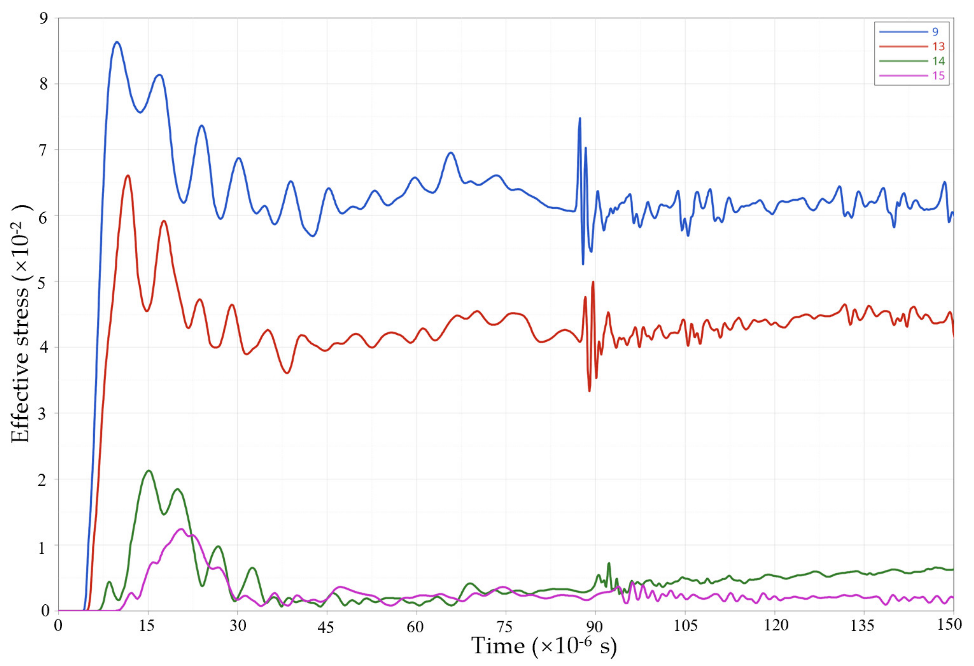
3.3. Numerical Simulation Results

Under the condition of single-hole ordinary blasting, the effective stress propagation process in the rock is shown in Figure 6. At t = 4.48 × 10⁻⁶ s, the stress wave is transmitted to the rock at the blasthole wall. At this time, the pressure is greater than the compressive strength of the rock, and the rock at the blasthole wall is initially damaged. When t = 4.5 × 10⁻⁶ s~10.48 × 10⁻⁶ s, under the action of the explosive stress wave, the damage range of the rock is increasing, and the maximum effective stress also increases. At t = 24.99 × 10⁻⁶ s, the rock at the blasthole was completely crushed, the stress wave gradually expanded outward, and the rock damage range continued to increase. The effective stress at the edge of the “circle” of the stress wave far exceeds the compressive strength of the rock. Therefore, it can be determined that the rock in the “circle” is damaged, and an explosion cavity is formed. When t = 24.99 × 10⁻⁶ s~34.45 × 10⁻⁶ s, the size of the “circle” increases continuously, and the explosion stress wave spreads out uniformly in a circular shape. At t = 34.45 × 10⁻⁶ s, the shock wave attenuates, and the impact on the rock is reduced. It can be seen that in ordinary blasting, the explosion stress wave always spreads outwards uniformly, and the effective stress at the same position from the center of the blast hole is basically the same.
Under the condition of energy-gathering blasting, the effective stress distribution of the surrounding rock is shown in Figure 7. After the explosive is detonated, the effect force is developed first, and the blasthole wall is initially damaged in the energy-gathering direction. Between t = 4.49 × 10⁻⁶ s and t = 11.46 × 10⁻⁶ s, the stress wave gradually propagates outward, and the effective stress range increases in the direction of gathering energy. Under the action of the explosive stress wave, the rock is damaged under pressure. Under the action of the explosive stress wave, the rock is destroyed under pressure in the energy-gathering direction. A t = 17.98 × 10⁻⁶ s, the stress wave continues to expand outward in a “circular arc” shape. Under the action of the explosive stress wave, the rock within the “circular arc” reaches a yielding state. At this time, the effective stress attenuates in the rock. The form of failure changes from compression to tensile failure. After t = 21.97 × 10⁻⁶ s, the stress concentration range of the blasthole wall increased, and the rock broke along the energy-gathering direction.
As shown in Figure 8a, in the ordinary blasting, measuring points 1, 2, 3, and 4 are arranged in the horizontal direction 1, 3, 5, and 10 cm from the center of the blasthole wall. In addition, 5, 6, 7, and 8 measuring points are arranged at the same distance in the vertical direction to monitor pressure changes at each point.
As shown in Figure 8b, in the energy-gathering blasting, the measuring points 9, 10, 11, and 12 are arranged at 0°, 30°, 45°, and 90° directions 1 cm from the blasthole wall. Monitoring points 13, 14, 15 are arranged at 3, 5, and 10 cm in the horizontal direction of the blasthole wall.
The effective stress change curve of each monitoring point of ordinary blasting is shown in Figure 9. After blasting, monitoring points 1 and 5 first reach the peak stress, and the monitoring point curves in the vertical and horizontal directions overlap at the same distance from the blasthole wall, and it is verified that the effective stress at the same position away from the blasthole in the case of ordinary blasting is basically the same size. After the effective stress of each monitoring point reaches the peak value, it gradually begins to weaken and finally approaches stability.
As shown in Figure 10, in the energy-gathering blasting, at the same distance from the blasthole wall, the effective stress peak value in the energy-focusing direction of the blasthole is 8.7 × 10⁻², and the stress peak value in the non-energy-gathering direction is 1.1 × 10⁻². The effective stress in the energy-gathering direction is 7.9 times that in the non-energy-gathering direction.
As shown in Figure 11, in the energy-gathering direction, monitoring point 9 first reaches the effective stress peak value of 8.7 × 10⁻² during blasting. At t = 11.3 × 10⁻⁶ s, monitoring point 13 reaches the peak stress value is 6.6 × 10⁻². With the propagation of the stress wave, the effective stress gradually weakens.

4. BBT In Situ Blasting Test

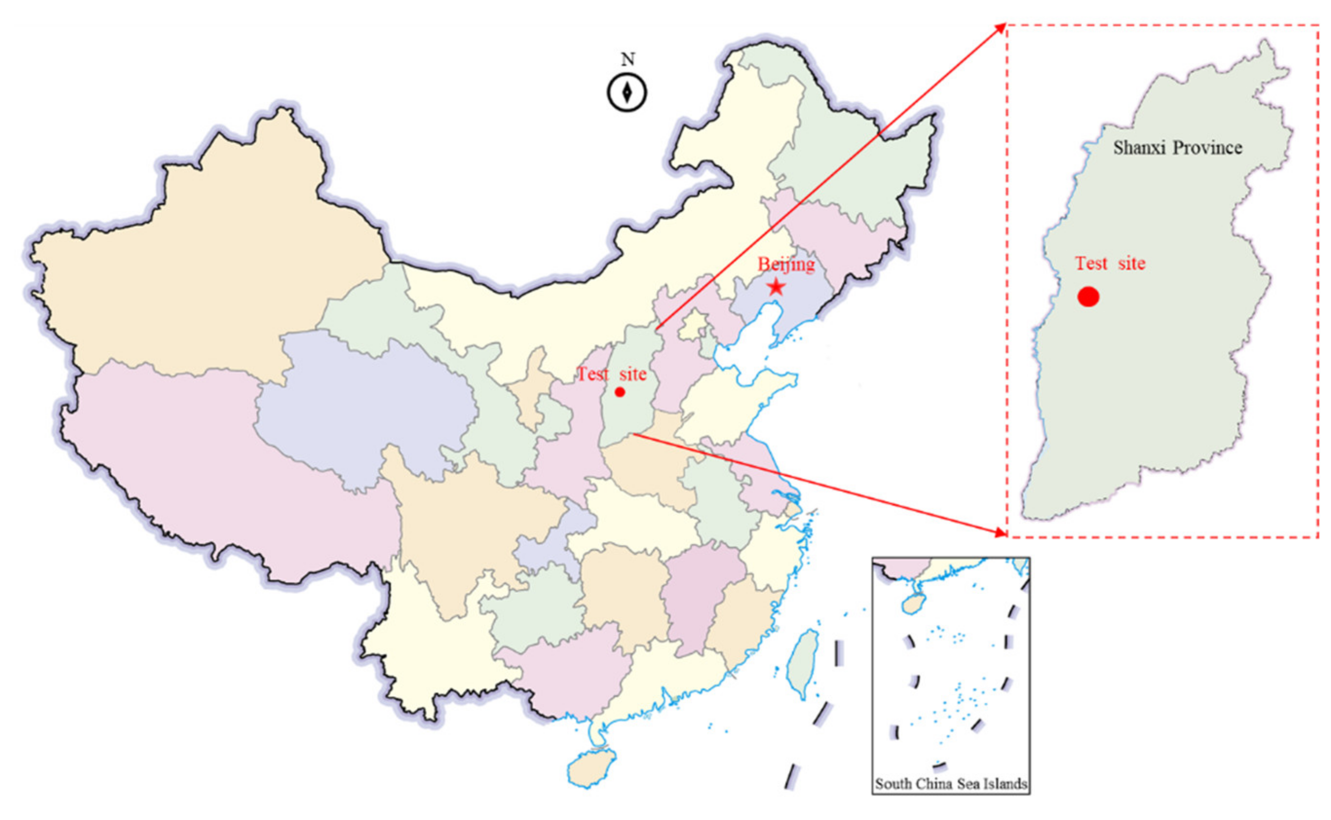
4.1. Engineering Geological Conditions

The field experiment was performed in the Shaqu No. 2 coal mine, which is located southwest of Liulin County, Lvliang City, Shanxi Province. Shaqu No. 2 Mine is a coal and gas outburst mine. The mine is about 9.7~14.5 km from north to south and 3.2~5.6 km from east to west. The area of the mine is about 63.4483 km2. The mine is located in the middle section of the Hedong coalfield, southwest of the Liliu mining area. The mine is currently mainly mined by the longwall mining method, and coal pillars are usually retained after adopting this method. The remaining coal pillars will cause much resource loss and create tension between mining and excavation continuity. The implementation of roof directional blasting technology for no-pillar mining technology in this mining area can increase the coal mining rate and ease the contradiction between coal mining and excavation continuity. This method is of great significance to the sustainable development of mining areas. The location of the test site is shown in Figure 12.

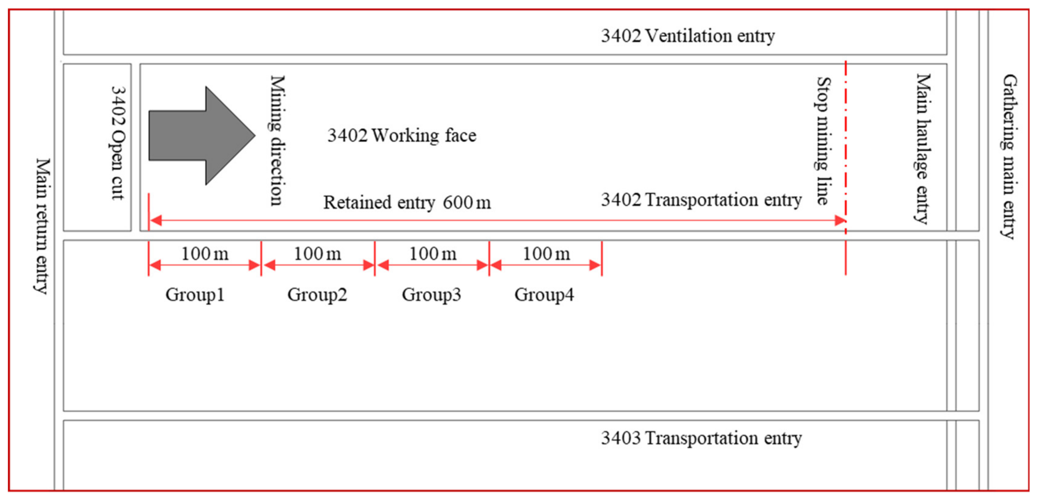
4.1.1. Test Working Face Conditions

The 3402 working face is located at level +470 m, coal 3# and mining area 2, and the buried depth of 380~450 m. The strike length is 840 m. The mining length is 600 m. The coal seam thickness ranges from 0.82 to 1.55 m, with an average thickness of 1.2 m. The relative gas content of 3# coal seam is 12.55 m3/t. The dip of the working face is 2°~7° with an average of 4°, and the working face has a length of 196 m. The 3402 working face layout and the entry-retaining position are presented in Figure 13.

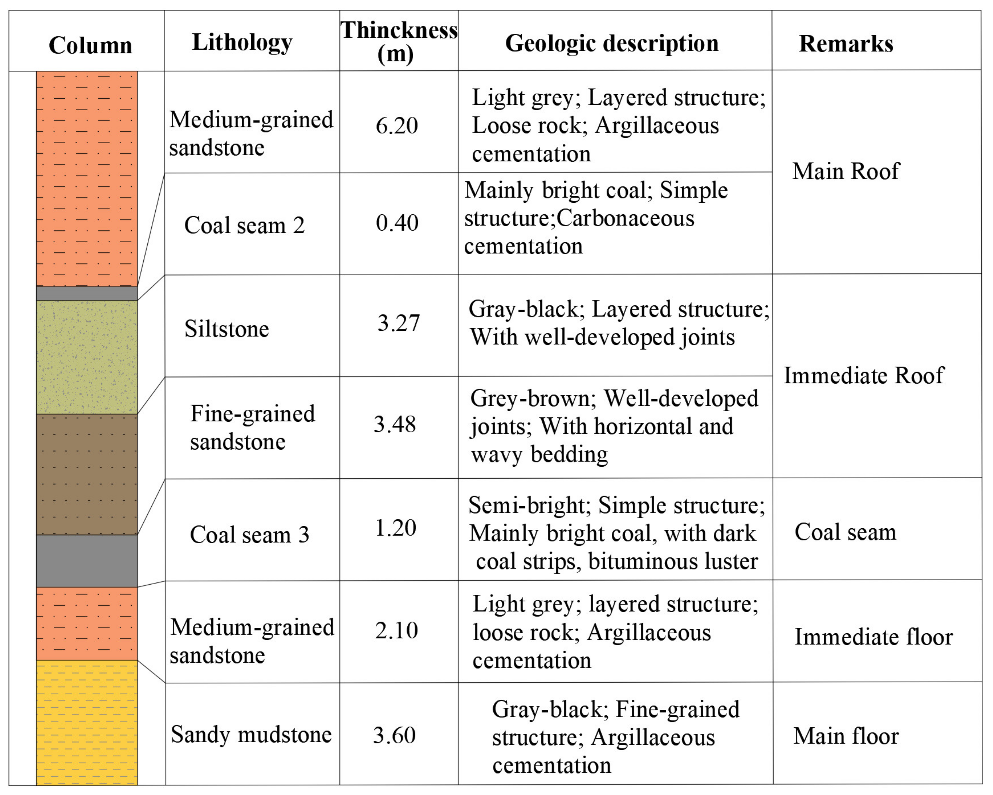
4.1.2. Coal Seam and Strata

According to the drilling column data of 3402 working face, the roof and floor of No. 3 coal seam are dominated by sandstone and mudstone. The average uniaxial compressive strength of the rock formation is 40.4 MPa, and the average uniaxial tensile strength of the rock formation is 3.15 MPa. The immediate roof of the No. 3 coal seam is composed of fine-grained sandstone with a thickness of 3.48 m and siltstone with a thickness of 3.27 m, with well-developed rock joints. The integrity of the rock mass is medium, and the rock mass is soft and belongs to the unstable roof. The main roof is composed of medium-grained sandstone with a thickness of 6.2 m, with massive bedding. The immediate floor is composed of medium-grained sandstone with a thickness of 2.1 m, with muddy stripes in the middle. The main floor is composed of 3.6 m sandy mudstone, with an average uniaxial compressive strength of 22.2 MPa and an average uniaxial tensile strength of 3.26 MPa. The rock layer has well-developed joints and is rich in plant stem fossils. The floor rock mass is soft and has suitable water resistance, and is summarized as an unstable floor. The lithology of the rock layers in the 3402 working face is shown in Figure 14.

4.2. Design of BBT

4.2.1. The Angle of BBT

Since the No. 3 coal seam is a thin coal seam, the difference from the medium-thick coal seam is that the immediate roof subsidence deformation space is small, and the realization of the roof cutting mainly depends on the gravity of the immediate roof and the shearing effect of the overburden load exerted by the roof sinking deformation on the immediate roof rock. Therefore, it is necessary to have a certain angle of BBT to avoid large frictional resistance on the roof-cutting surface, affecting the effect of the overall collapse of the immediate roof and the pressure relief. In order to minimize the friction in the roof-cutting surface, the calculation equation of the angle of BBT( θ ) is expressed as follows [42]:
θ = π 2 arctan L L R M
where M is the mining height, M = 1.5 m; L R is the width of the entry, L R = 4.2 m; and L is the length of the cantilever beam of the immediate roof. According to the statistical analysis of the 3402 working face of Shaqu No. 2 coal mine, L is taken as 9~11 m. Substituting these parameters into Equation (14), it can be obtained that the angle of BBT is 18.21~12.75°, and the angle of BBT was determined to be 15°.

4.2.2. Blasthole Depth of BBT

After the coal seam of the working face is mined, a certain space is formed, and the rock of the roof gradually collapses to form a goaf. Using the broken expansion characteristics of the rock, the roof within a certain range is cut by BBT so that the broken rock mass can be completely filled the mined-out area, forms a side of retaining entry. According to the rock mass bulk filling theory [43], the depth of BBT( H D ) is designed as follows [37]:
H D = M Δ H 1 Δ H 2 K p 1 cos θ
where Δ H 1 is the roof subsidence (m), Δ H 2 is the floor heaves (m), and K p is the broken expand coefficient.
According to the field measurement technique proposed in the literature [5], this design assumes that K is 1.38 and the max mining height of 3402 working face is 1.5. The angle of BBT is 15°. Since the floor heaves of the entry are not large and no obvious broken expand coefficient phenomenon has occurred, the roof subsidence and the broken expand coefficient of the floor are taken as 0. The depth of BBT is 6 m based on the calculation results and roof lithology.

4.2.3. Blasthole Distance of BBT

In energy-gathering blasting, the size of the blasthole distance directly affects the width of the crack and the penetration of the crack, and it is the main parameter to ensure that the roof of the entry can be fully cut. The diameter of the roof directional blasthole is generally 46~48 mm. The blasthole distance depends on the roof lithology. When the roof is a hard rock layer, the blasthole distance can be 500 mm; when the roof is a weak rock layer, the blast hole spacing can be 550 mm; when the roof is a broken rock layer, the blasthole distance can be 600 mm. In the case of composite rock formations, it is necessary to comprehensively determine the reasonable distance based on the field test results. The roof of the transportation lane of 3402 working face is siltstone, and fine-grained sand is within 6.75 m, which belongs to the composite sandstone roof, and the blast hole spacing is determined to be 500 mm.

4.3. Explosive Charge Structure Test

4.3.1. Plan of BBT

The BBT adopts an energy-gathering device with an outer diameter of 42 mm, an inner diameter of 36.5 mm, and a tube length of 1500 mm. The explosive used is the third-grade emulsion explosive of a coal mine, and each roll had a diameter of 32 mm, a length of 300 mm, and a mass of 300 g. The BBT adopts an uncoupled charge, the uncoupling coefficient is 1.42, and it is forward blasting. A total of three energy-gathering devices are installed in the blastholes with a length of 4 m, and the sealing mud length of the blasthole is 1.5 m.
According to the lithological characteristics of the roof in the range of energy-gathering blasting, combined with the previous engineering experience of roof cutting, four charging groups are tested in the field, and the charge structure for different test schemes is shown in Figure 15. The charge structure is “3 explosives + 2 explosives + 1 explosives”, “2 explosives + 1 explosives + 1 explosives”, “2 explosives + 2 explosives + 0 explosives” and “2 explosives + 2 explosives + 1 explosives” patterns, which corresponded to test group 1, group 2, group 3 and group 4, respectively.

4.3.2. Test Construction Process of BBT

According to the steps shown in Figure 16, the field experiment blasting test was carried out in an orderly manner according to the following steps. The main implementation processes of BBT were as follows:
Stage I: Prepare for the construction of the blasthole, determine the position of the drilling blasthole, the angle of the blasthole. Adjust the position of the drill to keep it on the designed roof-cutting line, As shown in Figure 16a.
Stage II: Start the construction of the blasthole, keep the drill level, use a drill with a diameter of 48 for blasthole construction, and strictly follow the designed drilling parameters to determine the depth of the blasthole to meet the requirements, as shown in Figure 16b.
Stage III: Installation of explosives and energy-gathering devices. According to the designed blasting parameters, the three-stage emulsion explosive of 32 mm × 300 mm is loaded into the first energy-gathering device and then loaded into the mine millisecond delay with a leg length of 8500 mm detonator; put the lead of the detonator through the energy connecting device, then put the explosive into the second energy-gathering devices, install a detonator; install this method, install the third energy-gathering devices, use 1.5 m sealing mud to seal after installation, as shown in Figure 16c.
Stage IV: First connect the three detonator leads in a single slit hole in series, then connect the detonators in adjacent blasthole in series, protect the surrounding equipment, evacuate all person, and set a safety distance of no less than 300 m, after checking that the gas content in the entry meets the requirements, start blasting, as shown in Figure 16d.
Stage V: After blasting, the blasthole orifice produced directional cracks, as shown in Figure 16e.
Stage VI: After the BBT, two rows of directional cracks were generated in the blasthole, as shown in Figure 16f.

5. Results and Discussion

5.1. Blasthole Crack Propagation

After the BBT is implemented, the CXK12(A) mine-used intrinsically safe drilling imaging system is used to observe the situation in the blasthole (as shown in Figure 17a), the system can visually observe various structures in blasthole, and the on-site peeping is shown in Figure 17b.
The results of drilling peeping under the four groups of blasting parameters, the statistical data of the development of slit holes and cracks, and the cracks in the blasthole of the four test groups are analyzed, as shown in Figure 18. In the first group of tests, the rock in the blasthole is relatively broken after blasting, the directional cracks in the hole are obvious, and a certain degree of damage to the integrity of the roof in the entry, which is not conducive to the maintenance of the later entry. In the second group of tests, the crack development is not obvious, and the directional crack is small. In the third group, the fracture effect of the siltstone section is better than that of the fine-grained sandstone section. There are fewer cracks at the bottom of the blasthole. In the fourth group, the cracks in the blasthole are obvious and completely penetrated. It has less impact on the roof.

5.2. Crack Growth Effectiveness

In order to better evaluate the blasting quality of blastholes, the crack ratio per meter ( C R ) is defined [44,45,46], as in Equation (16).
C R = l n 1 × 100 %
Through statistical analysis of the cracks in the blastholes, the single-hole charge and charge structure can be further optimized for the section with a lower fracture ratio to improve the blasting quality. As shown in Figure 19, in the four different test groups of charge structures, the overall crack ratio of the blasthole in the first group is the highest, the crack ratio in the bottom sealing section of the blasthole is 55%, the crack ratio in the fine-grained sandstone section at the bottom of the blasthole reaches 85%, and the crack ratio at the top of the blasthole reaches 98%. In the second group, the crack ratio in the middle of the blasthole is low, and the crack ratio in the middle of the blasthole should be adjusted. The crack ratio of the fine-grained sandstone at the bottom of the third group is 40%, which is relatively low. The crack ratios of the first and fourth groups both met the requirements, but the first group increased the amount of damage to the orifice and the roof increased. According to the cracks in the blasthole and the roof damage degree, the implementation of the project was carried out using the charging structure of 2 explosives + 2 explosives + 1 explosive and a sealing mud length of 1.5 m.

5.3. Entry-Retaining Results

The application effects of BBT are shown in Figure 20. In the process of BBT, the roof cutting of blasting work was completed 60 m ahead of the 3402 working face so as to avoid the damage to the blastholes by the advanced stress of the working face and effectively improve the blasting efficiency. With the mining of the working face, the gangue in the goaf on the roof-cutting side collapsed, and at the same time, the gangue was supported by air duct cloth, steel mesh, and U-shaped steel to form a bunch of entry. We sprayed the polymer material on the side of the gangue to plug and drain the gas in the goaf to ensure the safe production of the mine. With the continuous increase in the length of the retained entry by BBT, the retained entry gradually stabilized. Through on-site monitoring of the surrounding rock deformation of the entry, the approach of the roof and floor of the entry is about 300 mm, and the approach of the two sides is 75 mm. After the entry is stabilized, the entry is 2.4 m high and 4.0 m wide, which meets the requirements of safe production and ventilation in the mine. The BBT has achieved satisfied effects.

6. Conclusions

In this study, the bidirectional blasting technology (BBT) is introduced for composite sandstone roofs in the gob-side entry-retaining mining method. The BBT uses an energy-gathering device to achieve directional blasting of the roof of the entry and then uses the collapsed gangue to fill the goaf, assisting in the implementation of temporary support technology in the roadway, and realizes the gob-side entry-retaining mining method.
(1) The technical theory and mechanical model of BBT were established to analyze the propagation law of rock cracks. The numerical simulation models of ordinary blasting and energy-gathering blasting were established, and the distribution law of explosion stress wave under two blasting modes was analyzed under the composite sandstone roof. After ordinary blasting, a uniform stress wave of blasting stress is generated around the blast hole, forming circular damage and destruction. After BBT with the energy-gathering device, under the action of the blasting stress wave, bidirectional blasting of the rock can be realized in the energy-gathering direction under the composite sandstone roof.
(2) Using the energy-gathering effect of the energy-gathering device, the directional tensile failure of the rock can be realized under the composite sandstone roof. The BBT was applied to the 3402 working face of the Shaqu No. 2 coal mine, which was divided into four groups and conducted on-site blasting tests to determine the best “2 + 2 + 1 explosives” charge structure that can effectively produce cracks. According to the statistics of the crack ratio in the blasthole on site, the crack ratio of the blasthole reached 96%.
(3) After the mining, the U-shaped steel is used to support the gangue on the side of the goaf, and the monomer temporary support is used in the entry. Through on-site monitoring of the surrounding rock deformation of the gob-side retained entry by BBT, after the roadway is stabilized, the deformation of the two sides of the entry and the approaching amount of the roof and floor are 75 and 300 mm, respectively. The requirements for safe production in mines have been met. The blasting plan and charge structure have a certain guiding significance for determining reasonable blasting parameters in similar projects.

Author Contributions

Conceptualization, H.G. and Y.G.; methodology, Y.G., J.W., H.G. and Q.F.; validation, B.Q., Y.G. and X.W.; formal analysis, B.Q. and X.Z.; resources, Y.G. and J.W.; writing—original draft preparation, H.G.; writing—review and editing, Y.G.; supervision, Y.G.; project administration, Y.G. and J.W.; funding acquisition, Y.G. All authors have read and agreed to the published version of the manuscript.

Funding

This work is supported by the State Key Laboratory for Geomechanics and Deep Underground Engineering, China University of Mining & Technology, Beijing (No. SKLGDUEK1928) and funded by the China Postdoctoral Science Foundation (No. 2020T130702), which are gratefully acknowledged.

Institutional Review Board Statement

Not applicable.

Informed Consent Statement

Not applicable.

Data Availability Statement

The data used to support the findings of this study are available from the corresponding author upon request.

Conflicts of Interest

The authors declare that there is no conflict of interest regarding the publication of this paper.

References

  1. He, M.C.; Wang, Q.; Wu, Q.Y. Innovation and future of mining rock mechanics. J. Rock Mech. Geotech. Eng. 2021, 13, 1–21. [Google Scholar] [CrossRef]
  2. Zhu, Z.; Zhang, K.X.; He, M.C.; Yang, J.; Gao, Q.; Wei, Q.L. Surrounding rocks control technology and application of automatically formed roadway in mining without coal pillar and gateroad excavation. J. China Coal Soc. 2018, 43, 52–60. [Google Scholar]
  3. Peng, L.J.; Zhang, D.F.; Guo, Z.B.; Duan, Q.W. Numerical analysis of thick coal seam small pillar along gob roadway and its application. Rock Soil Mech. 2013, 34, 3619–3632. [Google Scholar]
  4. Zhang, G.C.; He, F.L.; Lai, Y.H.; Song, J.W.; Xiao, P. Reasonable width and control technique of segment coal pillar with high-intensity fully-mechanized caving mining. J. China Coal Soc. 2016, 41, 2188–2194. [Google Scholar]
  5. Lu, Y.Z.; Akhtar, S.; Sasmito, A.P.; Kurnia, J.C. Prediction of air flow, methane, and coal dust dispersion in a room and pillar mining face. Int. J. Min. Sci. Technol. 2017, 27, 657–662. [Google Scholar]
  6. Yang, K.; Gou, P.F. Research on Reasonable width of coal pillars in high strength mining roadway in Wantugou mine. Geotech. Geol. Eng. 2021, 39, 2065–2073. [Google Scholar] [CrossRef]
  7. Li, Y.F.; Hua, X.Z. Mechanical analysis of stability of key blocks of overlying strata for gob-side entry retaining and calculating width of roadside backfill. Rock Soil Mech. 2012, 33, 1134–1140. [Google Scholar]
  8. Bai, J.B.; Zhou, H.Q.; Hou, C.J. Development of support technology beside roadway in goaf-side entry retaining for new sublevel. J. China Univ. Min. Technol. 2004, 33, 183–186. [Google Scholar]
  9. Gao, Y.B.; Yang, J.; Zhang, X.Y.; Xue, H.J.; He, M.C. Study on surrounding rock control of roadways in deep coal mines based on roof cutting and pressure release technology by directional tensile blasting. Chin. J. Rock Mech. Eng. 2019, 38, 2045–2056. [Google Scholar]
  10. Gao, Y.B.; He, M.C.; Yang, J.; Ma, X.G. Experimental study of caving and distribution of gangues influenced by roof fracturing in pillarless mining with gob-side entry retaining. J. China Univ. Min. Technol. 2018, 47, 21–31. [Google Scholar]
  11. Wang, Q.; He, M.C.; Yang, J.; Gao, H.K.; Jiang, B.; Yu, H.C. Study of a no-pillar mining technique with automatically formed gob-side entry retaining for longwall mining in coal mines. Int. J. Rock Mech. Min. Sci. 2018, 110, 1–8. [Google Scholar] [CrossRef]
  12. Zhang, Z.Z.; Wang, W.J.; Li, S.Q.; Bai, J.B.; Hao, S.P.; Wu, H.; Yu, X.Y. An Innovative Approach for Gob-Side Entry Retaining With Thick and Hard Roof: A Case Study. Teh. Vjesn. Tech. Gaz. 2018, 25, 1028–1036. [Google Scholar]
  13. Meng, N.; Bai, J.B.; Chen, Y.; Wang, X.; Wu, W.; Wu, B. Stability analysis of roadside backfill body at gob-side entry retaining under combined static and dynamic loading. Eng. Fail. Anal. 2021, 127, 105531. [Google Scholar] [CrossRef]
  14. Chen, J.Y. Research on collaborative control technology for surrounding rock pressure relief and support of gob-side entry. Coal Sci. Technol. 2020, 48, 44–49. [Google Scholar]
  15. Su, B. Application of directional hydraulic fracturing and pressure relief technology for roof suspending at the working face end. Coal Eng. 2021, 53, 80–84. [Google Scholar]
  16. Zhang, R.; Cai, Q.W.; Huang, B.X. Deformation control of main roadway using roof hydraulic fracturing in Guqiao Coal Mine. Coal Eng. 2021, 53, 45–50. [Google Scholar]
  17. Pang, G.G. Hard roof hydraulic fracturing and the effect inspection. Coal Eng. 2021, 53, 27–30. [Google Scholar]
  18. Sun, Y.X.; Fu, Y.K.; Wang, T. Field application of directional hydraulic fracturing technology for controlling thick hard roof: A case study. Arab. J. Geosci. 2021, 14, 1–15. [Google Scholar] [CrossRef]
  19. Chen, Y.; Ma, S.; Yang, Y.; Meng, N.; Bai, J. Application of Shallow-Hole Blasting in Improving the Stability of Gob-Side Retaining Entry in Deep Mines: A Case Study. Energies 2019, 12, 3623. [Google Scholar] [CrossRef] [Green Version]
  20. Krol, R.; Kawalec, W.; Gladysiewicz, L. An Effective Belt Conveyor for Underground Ore Transportation Systems. IOP Conf. Ser. Earth Environ. Sci. 2017, 95, 042047. [Google Scholar] [CrossRef]
  21. Król, R. Studies of The Durability of Belt Conveyor Idlers with Working Loads Taken into Account. IOP Conf. Ser. Earth Environ. Sci. 2017, 95, 042054. [Google Scholar] [CrossRef] [Green Version]
  22. Król, R.; Kisielewski, W. Research of loading carrying idlers used in belt conveyor–practical applications. Diagnostyka 2014, 15, 67–73. [Google Scholar]
  23. He, M.C.; Cao, W.F.; Shan, R.L.; Wang, S.L. New blasting technology bilateral cumulative tensile explosion. Chin. J. Rock Mech. Eng. 2003, 22, 2047–2051. [Google Scholar]
  24. Gao, Y.B.; Wang, Y.J.; Yang, J.; Zhang, X.Y.; He, M.C. Meso- and macroeffects of roof split blasting on the stability of gateroad surroundings in an innovative nonpillar mining method. Tunn. Undergr. Space Technol. 2019, 90, 99–118. [Google Scholar] [CrossRef]
  25. Zhang, X.Y.; Hu, J.Z.; Xue, H.J.; Mao, W.B.; Gao, Y.B.; Yang, J.; He, M.C. Innovative approach based on roof cutting by energy-gathering blasting for protecting roadways in coal mines. Tunn. Undergr. Space Technol. 2020, 99, 103387. [Google Scholar] [CrossRef]
  26. Hu, J.; Zhang, X.; Gao, Y.; Ma, Z.; Xu, X.; Zhang, X. Directional presplit blasting in an innovative no-pillar mining approach. J. Geophys. Eng. 2019, 16, 875–893. [Google Scholar] [CrossRef]
  27. Zhang, X.Y.; Pak, R.Y.; Gao, Y.; Liu, C.; Zhang, C.; Yang, J.; He, M. Field experiment on directional roof presplitting for pressure relief of retained roadways. Int. J. Rock Mech. Min. Sci. 2020, 134, 104436. [Google Scholar] [CrossRef]
  28. Zhang, X.Y.; He, M.C.; Yang, J.; Wang, E.Y.; Zhang, J.B.; Sun, Y. An Innovative Non-Pillar Coal-Mining Technology with Automatically Formed Entry: A Case Study. Engineering 2020, 6, 1315–1329. [Google Scholar] [CrossRef]
  29. Guo, D.Y.; Shang, D.Y.; Lv, P.F.; Wang, S.Y.; Wang, J.M. Experimental research of deep-hole cumulative blasting in hard roof weakening. J. China Coal Soc. 2013, 7, 1149–1153. [Google Scholar]
  30. Zhang, Z.C. On the initiating, glowing branching and sloping of crack in rock blasting. Blasting 1999, 16, 21–24. [Google Scholar]
  31. Gao, Y.B.; Yang, J.; Wang, Q.; Wang, Y.J.; He, M.C. Mechanism of roof presplitting in a nonpillar mining method with entry auomatically retained and its influence on the strata behaviors. J. China Coal Soc. 2019, 44, 3349–3359. [Google Scholar]
  32. Yang, X.; Hou, L.; Xue, H.; Yuan, D.; Cao, J.; Han, Z.; Gao, Y. Pressure distribution and deformation control of gob-side entry retaining formed by roof cutting influenced by abandoned roadways. Geotech. Geol. Eng. 2021, 39, 2533–2545. [Google Scholar] [CrossRef]
  33. Sun, X.M.; Ye, C.L.; Hu, Y.C.; Zhang, K.; Liu, B.L.; Xue, Q.L. Numerical simulation analysis of rock blasting structure based on ANSYS/LSDYNA. Explor. Eng. Rock Soil Drill. Tunn. 2019, 46, 87–93. [Google Scholar]
  34. Hao, S.Y.; Bi, C.C.; Wang, Z.L. Study on Influence of Time Step on Calculation Result in Blasting Simulation with LS-DYNA. Blasting 2016, 33, 39–45. [Google Scholar]
  35. Ma, G.W.; An, X.M. Numerical simulation of blasting-induced rock fractures. Int. J. Rock Mech. Min. Sci. 2008, 45, 966–975. [Google Scholar] [CrossRef]
  36. He, M.C.; Guo, P.F.; Zhang, X.H.; Wang, J. Directional pre-cracking of roadway roof based on two-way energy-accumulating tension blasting theory. Explos. Shock Waves 2018, 38, 795–803. [Google Scholar]
  37. Yang, X.; Liu, C.; Ji, Y.; Zhang, X.; Wang, S. Research on roof cutting and pressure releasing technology of directional fracture blasting in dynamic pressure roadway. Geotech. Geol. Eng. 2019, 37, 1555–1567. [Google Scholar] [CrossRef]
  38. Steinberg, D.J.; Cochran, S.G.; Guinan, M.W. A constitutive model for metals applicable at high-strain rate. J. Appl. Phys. 1980, 51, 1498–1504. [Google Scholar] [CrossRef] [Green Version]
  39. Chen, W.S.; Hao, H.; Chen, S.Y. Numerical analysis of prestressed reinforced concrete beam subjected to blast loading. Mater. Des. 2015, 65, 662–674. [Google Scholar] [CrossRef]
  40. Li, N.; Zhao, J.H.; Wu, S.; Wang, J.; Shi, M.J. Blast response of steel fiber reinforced high strength concrete walls based on CONWEP. Eng. Blasting 2008, 12, 8–11. [Google Scholar]
  41. Li, H.C.; Chen, Y.; Liu, D.S.; Huang, Y.H.; Zhao, L. Sensitivity Analysis Determination and Optimization of Rock RHT Parameters. Trans. Beijing Inst. Technol. 2018, 38, 779–785. [Google Scholar]
  42. Guo, Z.B.; Wang, J.; Cao, T.P.; Chen, L.; Wang, J. Research on key parameters of gob-side entry retaining automatically formed by roof cutting and pressure release in thin coal seam mining. J. China Univ. Min. Technol. 2016, 05, 879–885. [Google Scholar]
  43. Xue, H.; Gao, Y.; Zhang, X.; Tian, X.; Wang, H.; Yuan, D. Directional Blasting Fracturing Technology for the Stability Control of Key Strata in Deep Thick Coal Mining. Energies 2019, 12, 4665. [Google Scholar] [CrossRef] [Green Version]
  44. Ma, X.G.; He, M.C.; LI, Z.; Liu, X.Y.; Yu, G.Y.; DU, H.R. Key parameters of gob-side entry retaining automatically formed by roof cutting and blasting in compound roof condition. J. China Univ. Min. Technol. 2019, 48, 236–246. [Google Scholar]
  45. Wang, Q.; Qin, Q.; Jiang, B.; Xu, S.; Zeng, Z.N.; Luan, Y.C.; Liu, B.H.; Zhang, H.J. Mechanized construction of fabricated arches for large-diameter tunnels. Autom. Constr. 2021, 124, 103583. [Google Scholar] [CrossRef]
  46. Wang, Q.; He, M.C.; Li, S.; Jiang, Z.H.; Wang, Y.; Qin, Q.; Jiang, B. Comparative study of model tests on automatically formed roadway and gob-side entry driving in deep coal mines. Int. J. Min. Sci. Technol. 2021, 31, 591–601. [Google Scholar] [CrossRef]
Figure 1. Energy-gathering device and model. (a) Energy-gathering device; (b) energy-gathering model [25].
Applsci 11 07524 g001
Figure 2. Rock tension crack model [25].
Applsci 11 07524 g002
Figure 3. Rock failure process. (a) Blasting; (b) crack formation; (c) crack propagation; (d) crack through [26].
Applsci 11 07524 g003
Figure 4. Mechanical model of BBT. (a) BBT is applied in the working face; (b) A-A section; (c) crack propagation model [27].
Applsci 11 07524 g004
Figure 5. Numerical model of ordinary blasting and energy-gathering blasting. (a) Meshing of energy-gathering blasting; (b) energy-gathering device and explosive; (c) meshing of ordinary blasting; (d) air and explosive.
Applsci 11 07524 g005
Figure 6. Effective stress distribution of ordinary blasting. (a) The effective stress at t = 4.48 × 10⁻⁶ s; (b) the effective stress at t = 10.48 × 10⁻⁶ s; (c) the effective stress at t = 24.99 × 10⁻⁶ s; (d) the effective stress at t = 34.45 × 10⁻⁶ s.
Applsci 11 07524 g006
Figure 7. Effective stress distribution of energy-gathering blasting. (a) The effective stress at t = 4.49 × 10⁻⁶ s; (b) the effective stress at t = 11.46 × 10⁻⁶ s; (c) the effective stress at t = 17.98 × 10⁻⁶ s; (d) the effective stress at t = 21.97 × 10⁻⁶ s.
Applsci 11 07524 g007
Figure 8. Monitoring point location. (a) Monitoring point under ordinary blasting; (b) monitoring point under energy-gathering blasting.
Applsci 11 07524 g008
Figure 9. Effective stress variation of ordinary blasting.
Applsci 11 07524 g009
Figure 10. Effective stress variation in non-energy-gathering direction of BBT.
Applsci 11 07524 g010
Figure 11. Effective stress variation in energy-gathering direction of BBT.
Applsci 11 07524 g011
Figure 12. Location of Shaqu No. 2 coal mine in Shanxi Province.
Applsci 11 07524 g012
Figure 13. The 3402 working face layout and the retained entry position.
Applsci 11 07524 g013
Figure 14. The lithology of the rock layers in the 3402 working face.
Applsci 11 07524 g014
Figure 15. Structure diagram of blasting charge.
Applsci 11 07524 g015
Figure 16. Implementation process of BBT. (a) Rig positioning; (b) drilling blastholes; (c) charging process; (d) blasting; (e) crack distribution at the blasthole orifice; (f) crack distribution in the blasthole.
Applsci 11 07524 g016
Figure 17. Borehole peeper test system. (a) the CXK12(A) drilling imaging system; (b) blasthole imaging.
Applsci 11 07524 g017
Figure 18. Image after directional blasting.
Applsci 11 07524 g018
Figure 19. Crack ratio of blasthole.
Applsci 11 07524 g019
Figure 20. The effects of entry-retaining by BBT. (a) Blasting before mining; (b) Gangue caving after mining; (c) Gangue support in goaf side of entry; (d) entry-retaining effects.
Applsci 11 07524 g020
Table 1. The parameters of the JWL equation.
ParameterA/GPaB/GPaR1R2ωVE0/GPa
Value3265.815.811.560.5712.67
Table 2. Energy-gathering device parameters.
ParameterC/(cm/μs)S1S2S3γ0aE
Value0.3871.82−0.075−0.0431.580.412.67 × 10−6
Table 3. Air parameters.
ParameterC0C1C2C3C4C5C6E0
Value00000.40.402.5 × 10−6
Publisher’s Note: MDPI stays neutral with regard to jurisdictional claims in published maps and institutional affiliations.

