1. Introduction
Recent developments in society show the use of robots for different kinds of applications. Robots have automated various sectors of society, reduced manpower, and assisted humans in places where they are restricted, or it is hazardous to work. A robot needs locomotion mechanisms to make it move through its environment, which can be accomplished by wheels, legs, etc. In recent years, the utilization of leg-based walking robots has turned out to be very efficient in the robotics field. These robots possess the ability to deal with irregular terrains, particularly when it’s compared with wheeled systems [
1,
2,
3]. Legged robot locomotion mechanisms, which are often inspired by biological systems, are very successful in moving through a wide area of rough and harsh environments. Legged robots are classified based on the number of legs used, such as biped, quadruped, hexapod, and so on. Quadruped robots are preferred among the other legged robots because of their less complex structure, giving the fullest requirements for the statically stable gaits during walking [
4]. Stability is a very important issue of a robot that is maintained as long as the center of mass (CoM) is within the support polygon which is a polygon with the vertices described by the position of legs in contact with the ground. Stability can be divided into static and dynamic stability criteria. Static stability is given when the CoM is within the support polygon and the polygon’s area is greater than zero. Therefore, static stability requires at least three points of ground contact [
1]. In general, it is extremely difficult to design gait controllers for legged robots. Various hand-crafted methods have been proposed to construct gait controllers, in which human supervision is needed in most cases [
5]. Song and Waldron defined gait as something that is defined by the time and the location of the placing and lifting of each foot, coordinated with the motion of the body in its six degrees of freedom, to move the body from one place to another [
6]. The observation, comprehension, and mathematical formulation of bio-inspired gaits were the main focus on legged locomotion, and it was found that many of these motions are periodic in nature. Gaits are generally classified as periodic and non-periodic, and it was found that the motion pattern of the quadruped robots is periodic [
7].
Many researchers have developed mathematical formulations of various biological gaits of quadruped robots that ensure maintaining static stability. Estremera et al. [
8] designed and implemented a mixture of free and discontinuous gaits to negotiate uneven terrain with a real machine. The fusion of these two main gaits plus the addition of extra constraints to avoid leg-transfer deadlocking produced a new free-crab gait, a free-spinning gait, and a free-turning gait. The developed gaits were tested on a SILO4 walking robot, and their algorithms were proved to be efficient in real-time and adaptive to irregular terrain. Wang et al. [
9] adopted a statically stable crawling gait as their main gait and proposed a fuzzy multi-model switching control based on friction compensation to achieve smooth switching of force and position. Their method was found to offer a solution for stable passage in a slope environment by realizing smooth switching of force/position, precise positioning in the swing process, and soft control of force in the supporting phase. Xi W et al. [
10] explored the benefits of using multiple gaits in a single robot and analyzed how increasing speed affects the choice of gait and how the choice of gait influences optimal speed. The authors used optimal control as a tool to identify motions that minimize the cost of transport of two detailed models: a planar biped and a planar quadruped. It was found that changing gaits as speed varies leads to the greatly increased energetic economy and concluded that for quadrupeds, the optimal gaits were four-beat walking at low speeds, trotting at intermediate speeds, and galloping at high speeds.
Due to the non-linearity of the system, rather than using a conventional approach, this research focuses on developing a metaheuristic algorithm to achieve various gaits. Metaheuristic algorithms are computational intelligence paradigms used especially for the sophisticated solving of optimization problems [
11]. This optimization is achieved by either minimizing or maximizing the solution through computing the fitness function. Winkler et al. [
12] presented an algorithm that generates walking motions for quadruped robots by simultaneously optimizing over both the center of mass (CoM) trajectory and the footholds without the use of an explicit footstep planner. Given a desired goal state, the problem was solved using a non-linear programming solver, and their results proved that the algorithm was able to generate walking gaits for multiple steps in milliseconds. Focchi et al. [
13] proposed a heuristic-based planning approach that enables a quadruped robot to successfully traverse a significantly rough environment in the absence of visual feedback. Their proposed framework included reflexes triggered in specific situations, and the possibility to estimate online an unknown time-varying disturbance and compensate for it.
Raheem et al. [
4] used a particle swarm optimization algorithm to find the best value of the stability margin during the robot walking gait. The quadruped robot kinematic model of the forward and inverse kinematics for each 3-DOF was calculated, which led to finding the minimum stability margins during walking on the vertical geometrical projection of the robot body. Their results demonstrated the best stability margins that guaranteed the preservation of robot COG within the support polygon. Similarly, Golubovic et al. [
5] presented an evolutionary algorithm for Sony-legged robots to learn good walking behaviors with little or no interaction with the designers. The algorithm was based on a hybrid approach that changes the probability of genetic operators concerning the performance of the operator’s offspring. The resulting gait was proved to be a better solution than the non-interference training for movements over all types of surfaces. Unlike other evolutionary algorithms like genetic algorithm (GA), and ant colony optimization (ACO), PSO achieved global convergence in a stipulated period of time. The former results in overlapping while the latter does not provide guaranteed convergence as the number of iterations increases.
The main goal of this paper is to develop robust gaits for the quadruped robot, and since the inverse kinematic equation can yield many solutions, it is necessary to determine an optimal value of joint angles to achieve efficient locomotion, which can be done by the use of metaheuristic algorithms. Thus, from literature studies and since PSO is simple, computationally efficient, has fewer parameters, and guarantees stable convergence [
14,
15], we have narrowed down our focus to develop a PSO algorithm to achieve various gaits.
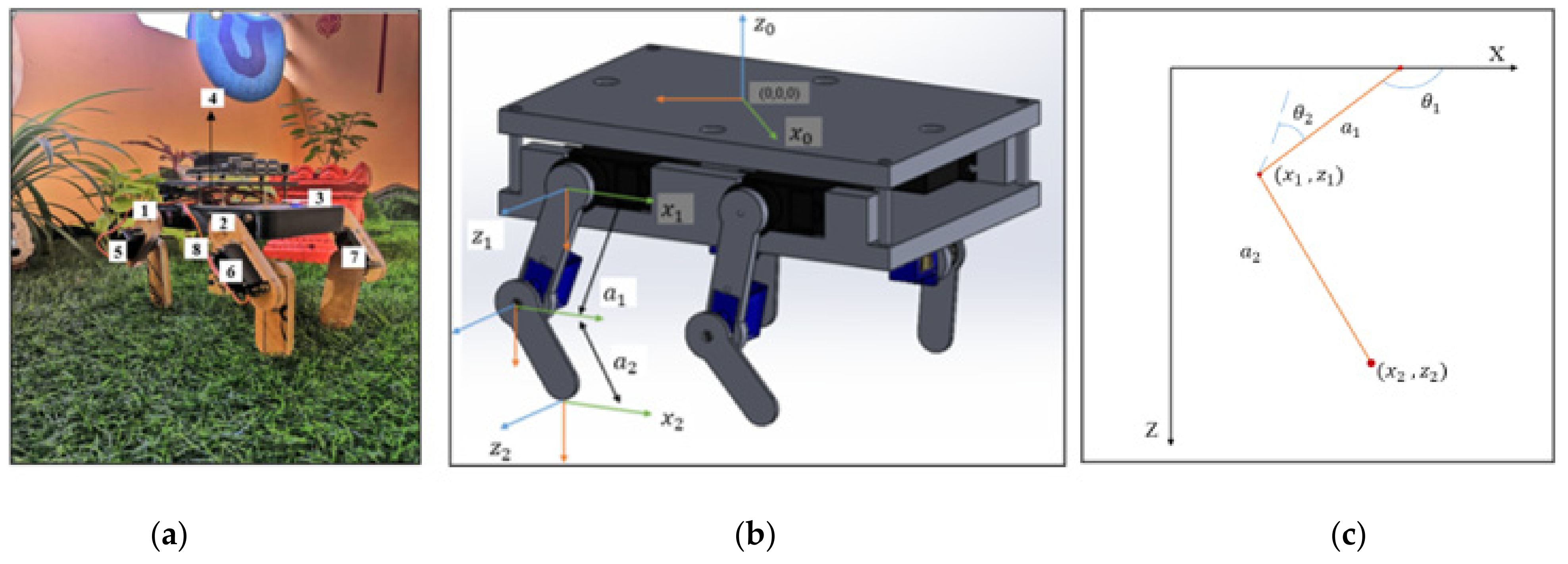
Hence, this work primarily focuses on the development and investigation of gaits for a 2 DoF mammal-inspired quadruped robot incorporating 4 hip and 4 knee motors as its locomotion element. Forward and inverse kinematics were formulated to determine the joint angles and stability analysis was carried out to ensure that the CoM and CoG lay within the support polygon. Walk, trot, and Pace gaits were developed using the particle swarm optimization algorithm to minimize the errors and improve the performance of the robot due to its non-linearity. The fitness function was derived based on the Euclidean distance between the target and robot’s current position, and kinematic equations were used to obtain the relation between joints and coordinates. Experimental studies were carried out quantitatively to determine the convergence characteristics of the control algorithm and to investigate the distance traveled by the robot for different target positions and gaits.
The rest of this paper is organized as follows.
Section 2 summarizes the mechanical and kinematic modeling of the quadruped robot.
Section 3 explains the stability calculations carried out to determine the CoM and CoG.
Section 4 describes the development of gaits using the PSO algorithm.
Section 5 discusses the experimental results obtained and benchmarks with the theoretical values. Finally, the outcomes of this research are concluded in
Section 6.
3. Stability Analysis of the Quadruped Robot
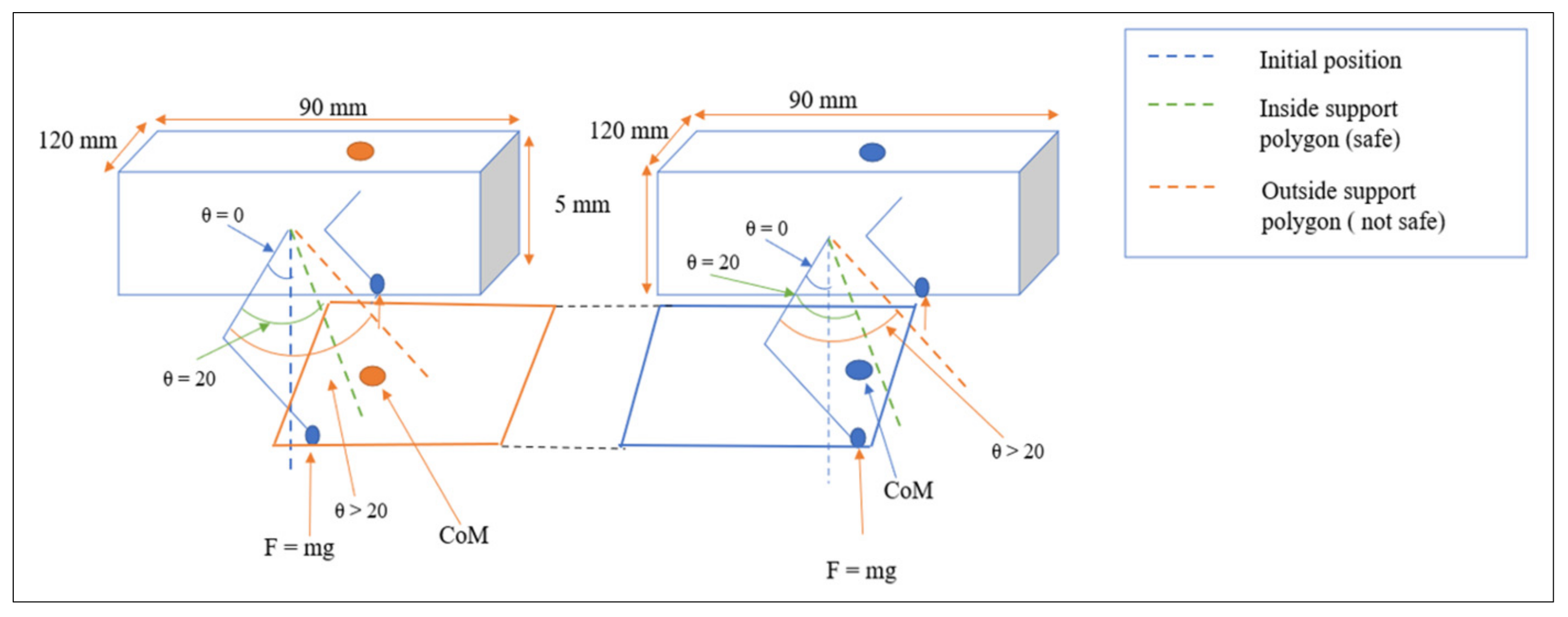
A robot is said to be stable if it regains its original position after external forces are exerted on it. To understand the movements and dynamism of quadruped robots, static stability and dynamic stability analysis are of great importance. Static stability is defined as the stability of a robot at every instant of time with the absence of motion. Static stability is given to a robot when the center of mass is completely within the support polygon (
Figure 2), which is a polygon with the vertices described by the position of legs in contact with the ground and whose area must be greater than zero. To determine whether the quadruped robot is statically stable, the following conditions must be achieved.
Figure 2.
Support polygon of the quadruped robot.
Figure 2.
Support polygon of the quadruped robot.
3.1. Moment of Stability ()
The moment is defined as the product of force acting on each link or each leg and the distance between the link or leg to the ground and is calculated as,
The conditions to achieve are,
where,
is the moment at which stability is achieved;
are the moments of each leg.
where,
and
are the individual moments of the two links that form a single leg. As torque values are known, force is calculated using the below equation;
The moment for link 1(
) =
=
. In the same manner, the moment for link 2 (
) is found to be
Thus, the total moment acting on the leg (
) is
. Since the legs are symmetric, the moments for the other legs will also be within the range of the moment of the calculated leg. The conditions for
are satisfied as to the value of
is greater than zero and the same moment at stability is the minimum of the moment of the other legs.
Therefore, the moment at which stability is achieved should have a value that is greater than or equal to 23 .
3.2. Center of Gravity (CoG)
Center of gravity (CoG) is defined as the point at which the force of gravity of the overall body acts. The center of gravity must lie within the area of support polygon and is calculated as below.
where,
is the sum of the moment acting on all the legs;
is the sum of all the mass of the motors. As
and
are known, the CoG was found to be 11.5 cm. So, the center of gravity is at a distance of 11.5 cm from the reference point (0,0,0), which was taken concerning the frame of the robot.
3.3. Center of Mass (CoM)
Center of mass is defined as the point at which the resultant mass of the body of the robot acts and is mathematically defined as,
Determining the distance of the motors from the reference point and knowing the mass of the motors, the CoM along x and y axes was found to be (8.8, 7.64). Thus, CoM is located at a distance of 11.65 cm from the reference point. Since the area of support polygon is in the shape of a parallelogram, the area was found to be 161.5 . As the CoG and CoM are within the area of support polygon and conditions are satisfied, the robot is concluded to be statically stable.
4. Gait Development Using PSO
Gait development is the selection and formulation of a coordinated sequence of legs and body motions that propels the robot along a desired path [
17]. During locomotion, each leg is swung forward and then retracted to contact the ground. Quadrupeds commonly use two types of gaits, i.e., symmetrical gaits (e.g., pace, walk, or trot) where the footfalls of the pair of are evenly spaced in time and asymmetrical gaits (e.g., gallop, bound) where the actions in at least one pair are unevenly spaced in time [
18]. This paper focuses on the development of the three common symmetrical gaits, i.e., walk, trot and pace, for the quadruped robot using particle swarm optimization algorithm and kinematic equations. The gaits are considered according to speed and efficiency since a real-time reasonable selection of walking pattern is necessary to maintain the best walking balance.
- A.
Walk Gait Implementation
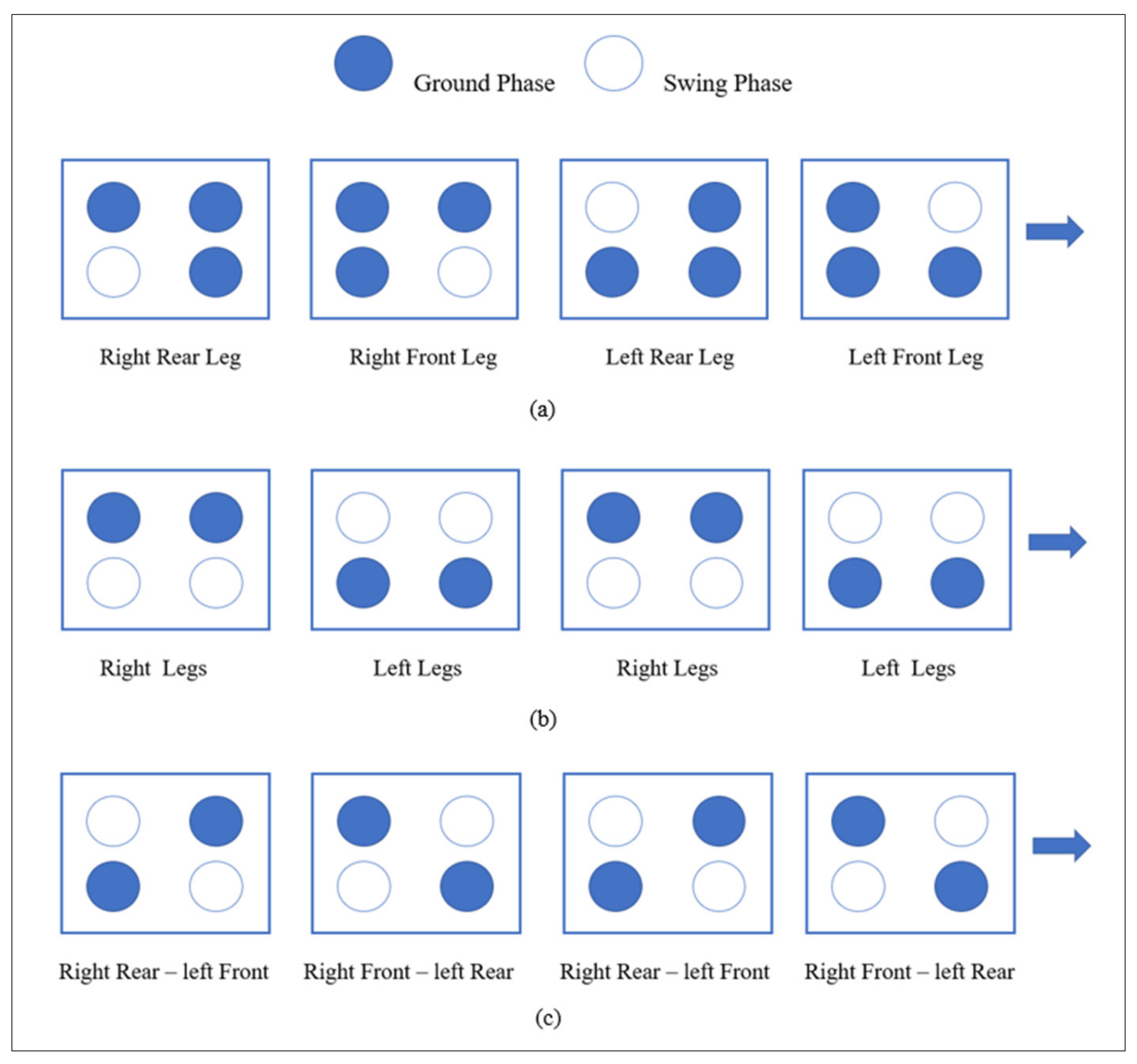
The walk is the slowest and most energy-efficient gait [
19]. It is a periodic continuous four-beat gait, in which each leg steps sequentially. The walk step sequence is shown in
Figure 3a. In the normal walk gait, two legs alternate with three legs in supporting body weight. Several types of walk gaits are recognized based on variations in leg support, stride length, and step speed.
- B.
Pace Gait Implementation
The pace is a two-beat gait. The two lateral limbs are used alternately for weight support, i.e., the left forelimb and left hindlimb move in unison, as do both right limbs. The foreleg may cycle slightly earlier than the ipsilateral hindleg. The step sequence of the trot is shown in
Figure 3b. A short period of suspension typically intervenes between the alternating phases of lateral support, particularly at increased speed. The rack gait is a rapid pace in which the two ipsilateral limbs land separately instead of together, producing a four-beat gait. The pace gait can be used with some range of speed, and naturally as the speed increases, the moment of suspension between beats will increase as well [
19].
- C.
Trot Gait Implementation
The trot is a two-beat gait. Right and left diagonals alternate in supporting weight, i.e., the right foreleg and left hind leg move in unison, as do the left foreleg and right hind leg. The step sequence of the trot is shown in
Figure 3c. Twice during each step, the body is ballistic and without help or support from any other body. In trot gait, the pattern of movement is quick compared to other gaits and is one of the most stable gaits but improving its dynamic characteristics is a challenging task. The trot is a common gait in all domestic quadrupeds. It is well-suited for rough, irregular ground and for traveling long distances at a fair rate of speed. Work is spread evenly over all four limbs, and diagonal support makes it easy to maintain equilibrium [
19].
4.1. Particle Swarm Optimization (PSO)
In a PSO system, multiple candidate solutions coexist and collaborate simultaneously. Each solution candidate, called a particle, flies in the problem search space looking for the optimal position to land [
20]. Each particle in PSO has two important components, (i) Position
and (ii) Velocity (
).
As time passes, every particle adjusts its position and velocity according to its own experience (personal best or P
best) as well as according to the experience of neighbouring particles (global best or G
best). The equations for updating the velocity and position of the particle are as follows [
21].
and are the acceleration co-efficient that controls the maximum step size the particles can do and ‘’ is the inertial weight. Together they control the impact of previous historical values of particle velocities on its current one and and are two random functions with a range [0, 1].
Thus, Equation (12) is used to calculate the particle’s new velocity according to its previous velocity and the distances of its current position from both its own best historical position and its neighbor’s best position. Then, the particle flies toward a new position according to Equation (13). The performance of each particle is measured according to a pre-defined fitness function, and this process is repeated until the user-defined stopping criterion is satisfied.
4.2. Mathematical Formulation of Fitness Function
The Fitness Function is planned to be formulated in such a way that an optimized inverse kinematic solution will be obtained considering the following constraints.
Center of mass (CoM) and center of gravity (CoG)—For the robot to stay stable during static and dynamic conditions, the CoM and CoG of the robot must stay within the support polygon.
Maximum angle of links of the robot—It must be ensured that the legs do not cross the maximum angle so that the CoM and CoG of the robot lie within the polygon.
Assume the initial position to be
(
and target position to be
(
. A PSO particle is given by
= {
,
}, Where Q
i is a set of possible joint angles subjected to the following constraints.
After applying the joint angles in the forward kinematic equation, the robot position in a reference frame can be obtained as,
(
= (
X1,
X2......
Xn) This position is compared with the target position,
Xt. Hence, the fitness function, f is given as the Euclidean distance between the target position and the obtained robot position.
4.3. PSO Algorithm Implementation and its Significance
Inverse kinematics is a key issue in robotics, especially for problems such as path planning, motion generation, or trajectories optimization. It becomes very tedious to calculate with many degrees of freedom, and also, the results are not optimal. Since the focus of this paper is to develop robust gaits for the quadruped robot and, it is necessary to determine an optimal value of joint angles to achieve efficient locomotion. Due to this non-linearity of the system, rather than using a conventional approach, PSO is a very efficient method. As all the legs are symmetric to each other, it is sufficient to run the algorithm for one leg and utilize the results obtained for the other legs. Thus, through the PSO algorithm, we are accelerating each particle, i.e., joint variables towards the P
best and G
best through repetitive iterations to obtain the optimal joint variables. The pseudo code of the developed PSO algorithms is given as Algorithm 1 below.
| Algorithm 1 PSO Algorithm Implementation |
![Applsci 11 07458 i001]() |
5. Experimental Results and Discussions
Determining the joint angles in an efficient way during dynamic locomotion is a challenging task. As the robot traverses through the terrains, the joint angle limits are not going to be the same. Each leg will require a desired joint angle depending on various constraints such as the frame of the robot, stability, and the compensation of the angle on each leg due to angle requirement on other legs of the robot. The novelty of this paper lies in the development of a PSO algorithm considering kinematic solutions to achieve an optimal joint angle in an efficient manner. The algorithm is implemented in Python programming language using Visual Studio Code/Python Editor through Linux OS (Ubuntu Version 18.04).
Table 3 gives the proposed PSO algorithms parameters. Since each leg consists of 2 DoF, the dimension of each particle is 2. The acceleration coefficients (C
1, C
2) define the magnitude of the influence on the particles velocity in the directions of the local and the global optima. To have a better balance of search space between local and global exploration, it is good to assign a value between 1.0 and 2.0. Similarly, inertia weight (ω), plays a major role in determining the proportional relationship between local and global convergence. Since a larger inertia weight tends to facilitate global exploration, whereas a smaller inertia weight facilitates local exploration, the value is set to be 0.5. Using Pyswarms’s built-in optimizer function, the objective function (Equation (15)) is optimized, and the constraints are passed as its arguments.
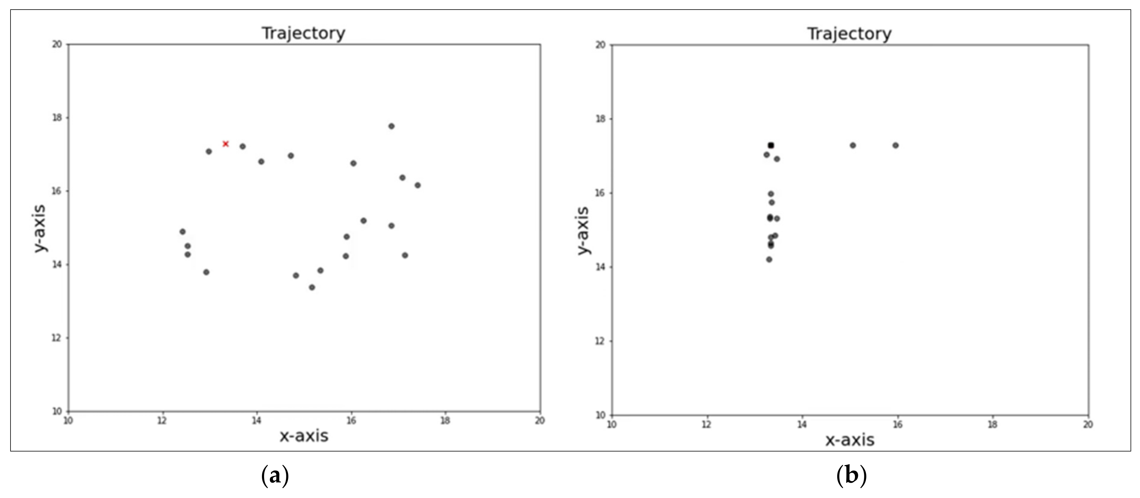
The algorithm is made to run for 1000 iterations and the best cost and the optimal joint variables to reach the target position of (10,0,0) are obtained as 1.14 × 10
−14 and [13.34, 17.29], respectively.
Figure 4a,b shows the movement of the swarm towards the global best (marked in the red cross) where the x and y-axis correspond to the joint variables
and
in degrees, respectively, and
Figure 5 shows the experimental setup. In addition, a graph between the number of iterations and cost is shown in
Figure 6, where the best cost was found to decrease.
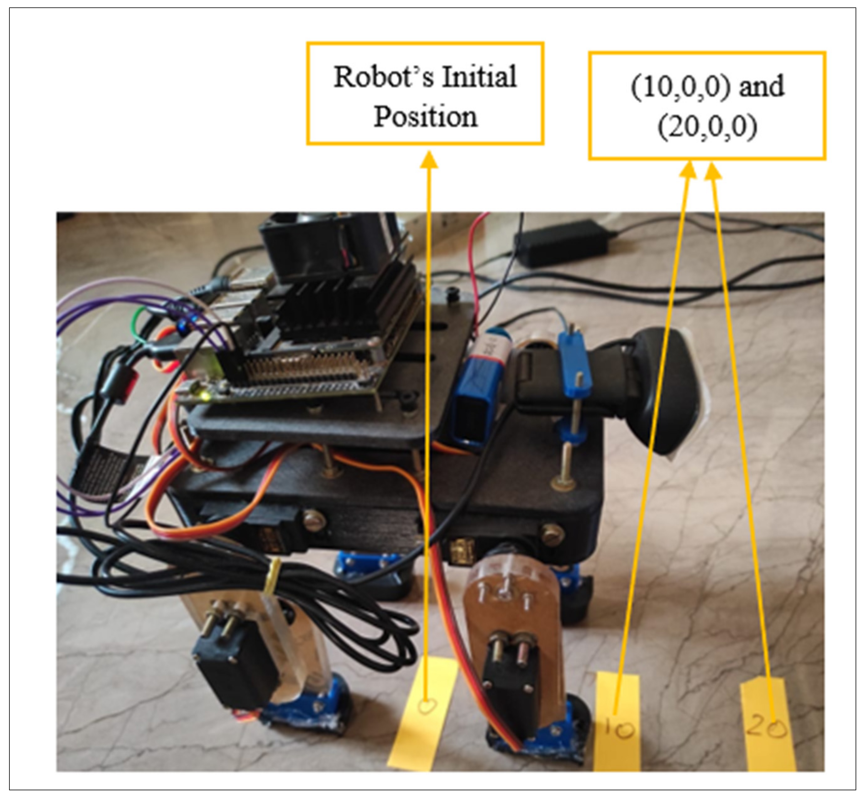
To understand the convergence rate of the algorithm, the distance the robot travels, and computational time, the code is made to run five times for different target positions and be implemented in the robot. The results are tabulated in
Table 4, where the target is given as (10,0,0) and (20,0,0), which describes the movement of the robot on the x-axis for a distance of 10 mm and 20 mm. Thus, it is understood that the algorithm was able to achieve the best/global cost of 1.14 × 10
−14 for the target value of (10,0,0) and 1.00 for (20,0,0), respectively. This ensures that the algorithm was able to achieve global convergence.
It is seen that the run time of the algorithm is around 1.80 s which proves the algorithm to be computationally efficient. In addition, it is understood that for a target value of 10, the robot moves 10 mm forward in a single step, and similarly, for a target value of 20, the robot moves 20 mm in a single step. Hence, an investigation between the theoretical and experimental values has been carried out and presented in
Table 5 for the three gaits considered. The error has been calculated as given in Equation (16).
where
dT and
dE are the distance traveled by the robot estimated in theoretical and experimental, respectively. For this investigation, the robot was made to travel a distance of 10 cm, 20 cm, 100 cm, and 200 cm as tabulated in
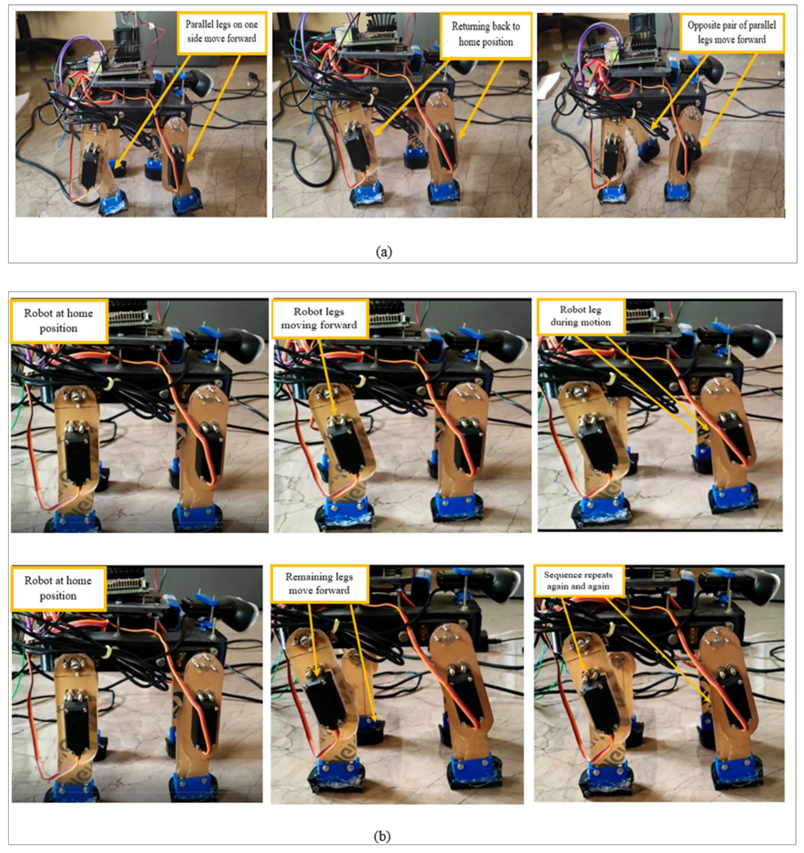
Table 5, and the actual distance traveled by the robot is noted. It can be found that the robot was not able to exactly reach the target position. This error can be due to the slippage or loose ground contact during the motion. In particular, it can be seen that a maximum error of 5.2 % on average was produced by the walk gait, while the trot and pace gait was found to produce a minimum error of 1.31 and 3.31%, respectively. These results support the statement that trot gait is the most stable and improves the dynamic characteristics of the robot. Since walk is a very slow gait, the robot might be prone to errors reducing the efficiency. Overall, the robot was able to achieve the gait patterns with a maximum error of only 10%, which can be further reduced, improving the stability and foot-ground contacts. Furthermore, the time taken to reach the target was found to determine the velocity of the robot. It can be seen that the velocity of the robot is not constant during all the gaits. On average, the walk gait had a velocity of 0.246 cm/s, the trot gait had 0.42 cm/s velocity, and the pace gait was 0.307 cm/s. Thus, it is understood that since walk gait is the slowest of the three, it has the lowest velocity, while trot has the highest velocity. But, however, it should be taken into consideration that the time taken for the robot to reach the targets in all three gaits is high, which in turn results in low speed. The sequence of the robot performing the three gaits is presented below in
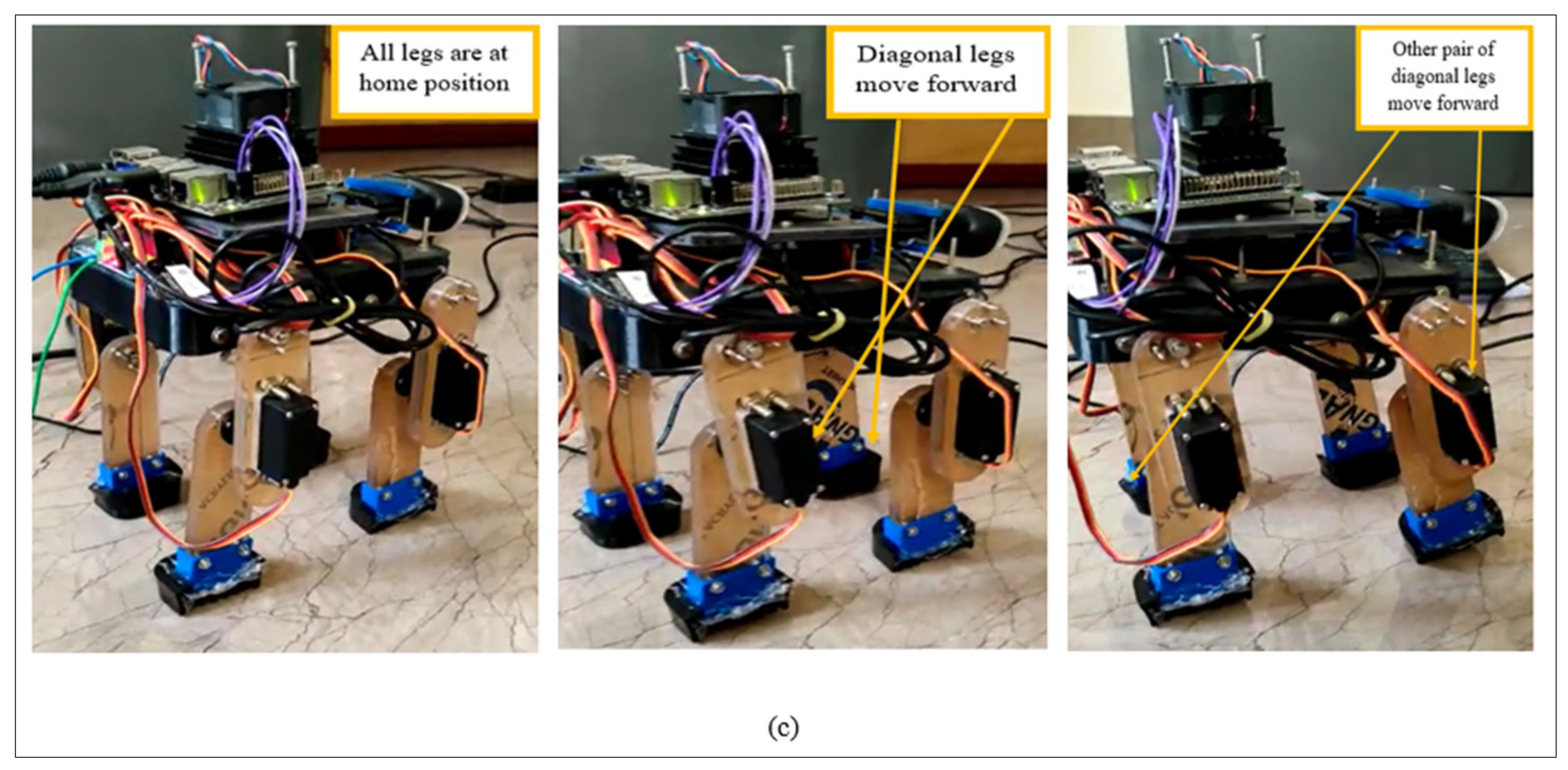
Figure 7.
Figure 7a represents the pace gait pattern where the parallel legs on either side of the robot move forward together.
Figure 7b represents the walk gait where the sequence was as follows; right hind leg, left front leg, right front leg, and left hind leg. Finally,
Figure 7c represents the trot gait where the diagonally opposite pair of legs move forward achieving in forward motion of the robot.
The developed algorithm can be applied for any type of legged robots, not restricted to only quadruped robots, but is limited to only flat terrain. With the establishment of the locomotion pattern, the algorithm will be able to determine the optimal joint angle and minimize the errors produced in the system by compensating for the joint angle required to make the robot reach the target destination. All the abbreviations and symbols used in this work are tabulated in
Table 6 for the ease of readability.
6. Conclusions
The use of legged robots over wheeled robots has demonstrated convincible advantages to society. These types of robots can replace humans working in military areas as well as assists humans in industries and other urban-related applications. In appraising the advantages of legged robots, this paper presented the development and investigations of various gaits for a 2 DoF mammal-inspired quadruped robot that incorporated four hip and four knee joints actuated by electronic servo motors as its locomotion element. Several analyses such as forward and inverse kinematics and stability analysis have been developed and discussed to achieve an efficient gait pattern of the robot. Due to the non-linearity of the system, particle swarm optimization (PSO) has been considered for the development of the control system. This paper focused on the development of three common symmetric gaits, i.e., walk, trot and pace. The robot was studied and investigated in three ways based on the number of steps taken to achieve the target. The robot took 10, 100, and 200 steps to reach a distance of 10, 100, and 200 cm by all the three types of gaits. Parameters like velocity, time taken, and actual distance traveled were considered to evaluate the performance of the robot. The proposed algorithm was able to achieve global convergence of 90%, and based upon the investigations carried out it was found that the maximum error was demonstrated by walk gait, and minimum error was found during trot gait implementation. On average, the maximum error produced by the robot during all the gaits was found to be only 10%. The robot will be further studied at different speeds of motion and has to be tested in climbing at different angles to test out the off-road ability of the robot. Future works of this research include improving the performance of the current robot, developing dynamic control strategies by implementing deep learning-based neural networks to ensure the stability of the robot during the transient state, and comparing the performance of the developed algorithm with classical algorithms such as central pattern generator (CPG) and other optimization algorithms.


 ,
, 


