Article

Comparison of Gamma and Neutron Dose Rate Variations with Time for Cast Iron and Metal–Concrete Casks Used for RBMK-1500 Spent Fuel Storage

Nuclear Engineering Laboratory, Lithuanian Energy Institute, Breslaujos 3, 44403 Kaunas, Lithuania
*
Author to whom correspondence should be addressed.
Appl. Sci. 2021, 11(16), 7362; https://doi.org/10.3390/app11167362
Submission received: 22 July 2021 / Revised: 5 August 2021 / Accepted: 9 August 2021 / Published: 10 August 2021
(This article belongs to the Special Issue Nuclear Wastes Management)

Abstract

:
The present SF management concept in Lithuania envisages that spent RBMK-1500 fuel will be stored in dry storage containers for 50 years, before being disposed of in a deep geological repository. However, the risk that a deep geological repository will not be constructed at the planned time should be taken into account, and the extension of SF storage over 50 years should be considered. This paper presents a comparison of gamma and neutron dose rate distributions and variations with planned and extended storage times for cast iron and metal–concrete containers loaded with RBMK-1500 SF. All calculations were performed using the SCALE computer codes system. The modeling results show that the overall shielding properties of the CONSTOR® RBMK-1500 container containing the same neutron and gamma sources are better than those of the CASTOR® RBMK-1500 container. During an extended storage period (from 50 to 300 years), the total dose rate would decrease considerably and the dose rate due to neutrons would become dominant for both containers.

1. Introduction

A few decades ago, in many countries that operate nuclear reactors, the original intention was that SF would be reprocessed or disposed of. However, in the 1990s, most countries canceled their plans for SF reprocessing, but deep geological repositories were not available at that time. Therefore, a need for interim SF storage has emerged. Currently, two main SF storage concepts are used worldwide, i.e., wet storage in pools and dry storage in containers or vaults [1]. Due to the absence of the possibility to reprocesses RBMK-1500 SF, the interim dry storage (in containers) concept has been implemented in the Ignalina Nuclear Power Plant (NPP). Reprocessing is not foreseen, and the dry storage concept (in vaults) is also used in other countries (Ukraine, Russia) that have RBMK type reactors [2,3,4]. The exception is damaged RBMK-1000 SF assemblies that are not allowed to be placed into dry storage facilities in Russia; therefore, these damaged assemblies are reprocessed [5].
There are two dry storage facilities (ISFS-1 and ISFS-2) at the Ignalina NPP site for interim storage of the whole RBMK-1500 spent fuel (SF) that was generated during the operation of Ignalina NPP. Ignalina NPP consists of two RBMK-1500 reactor units that were permanently shut down in 2004 and 2009, one at a time. ISFS-1 started its operation in 1999 and was completely loaded in 2010. Cast iron (CASTOR®) and metal–concrete (CONSTOR®) containers loaded with RBMK-1500 SF are stored at ISFS-1. ISFS-2 started operation in 2016 and is designed to store the CONSTOR® RBMK-1500/M2 type containers. This container type was not analyzed in this paper.
In previous publications concerning the shielding analysis of cast iron and metal–concrete containers used for RBMK-1500 SF storage [6,7,8], radiation characteristics of spent fuel and resulting dose rates for these storage containers were estimated up to the planned storage time (50 years). A few papers provided comparisons between measured dose rates at ISFS-1 of Ignalina NPP and calculated dose rates for cast iron and metal–concrete containers [9,10,11]. Some results on dose rate evaluations for extended storage periods were performed and presented in [12]. Similar evaluations for extended storage of TN-32 container containing other types of SF were provided in [13]. It should be emphasized that the typical design lifetime of dry storage containers is 40–60 years. Extension of storage time beyond the container’s design lifetime requires justification that the aging mechanisms [14,15] would not jeopardize their safety. Otherwise, SF after the planned interim storage time should be repackaged into a new container. The results presented in this paper focus on the peculiarities of energy distributions of gamma and neutron emissions from the spent fuel loaded inside the containers. The performed analysis shows what energy groups provide major contributions to the dose rate on the surface of the containers for extended storage periods.

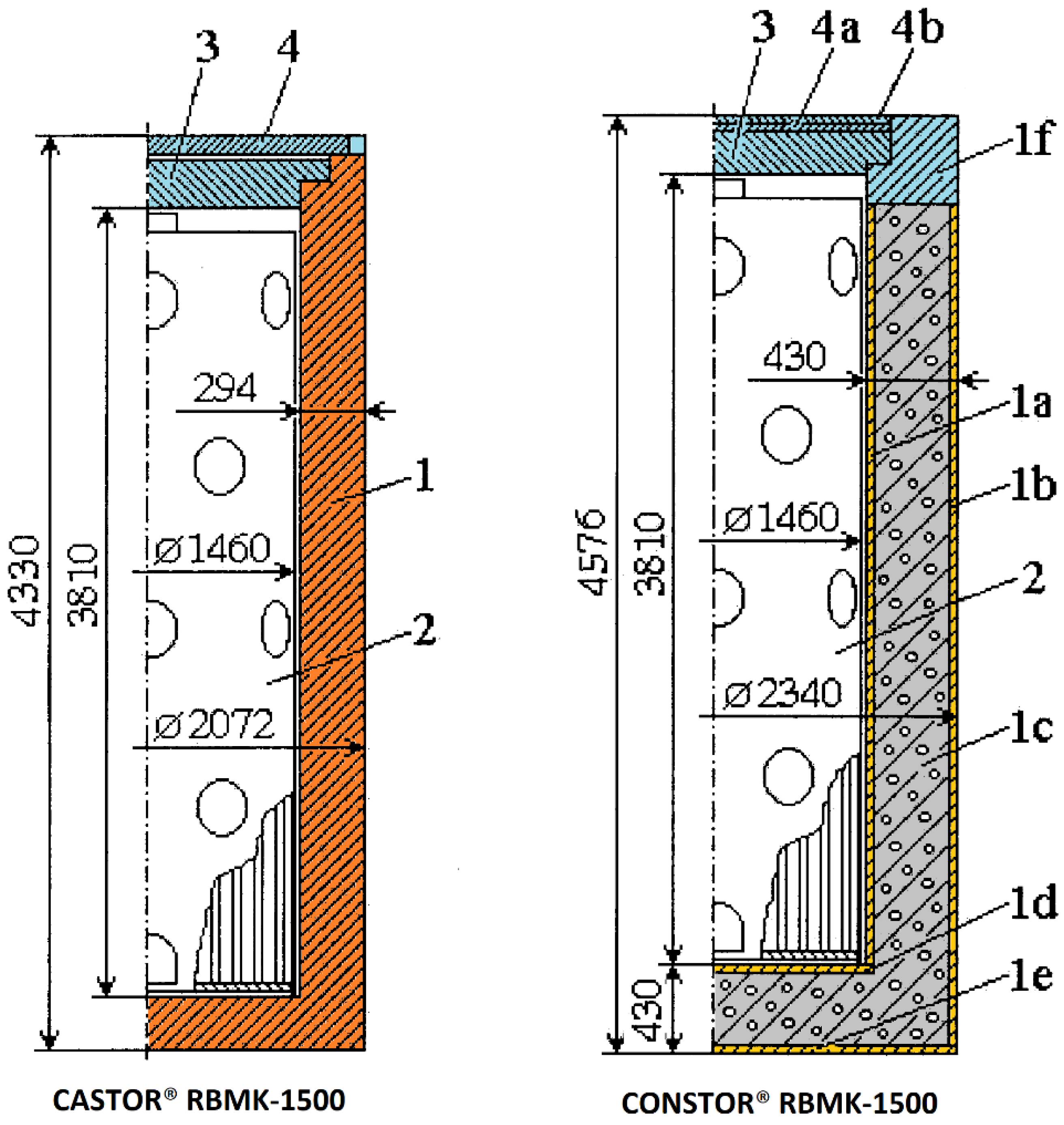
2. Containers Used for RBMK-1500 Spent Fuel Storage

Three container types are used for RBMK-1500 spent fuel dry storage at Ignalina NPP site—cast iron (CASTOR®), metal–concrete (CONSTOR®), and metal–concrete (CONSTOR® M2). The third option has increased SF storage capacity and, thus, was not analyzed in this paper. The cast iron container has a cylindrical body manufactured of ductile cast iron. The height of the container is 4.33 m, the diameter is 2.07 m, and the wall thickness is 0.29 m. The container is closed with a leakproof bolted double-lid system. The mass of the cast iron container loaded with RBMK-1500 SF is about 75 tons. The sidewall of a metal–concrete container consists of inner and outer steel cylinders. Reinforced heavy concrete is within the space between these cylinders. The bottom of the container’s body is similar, i.e., the space between the two steel plates is filled with reinforced heavy concrete. The total thickness of the sidewall is 0.43 m. The height of the metal–concrete container is 4.58 m, and the diameter is 2.34 m The leakproof lid system consists of a bolted lid and two welded lids. The mass of a metal–concrete container loaded with RBMK-1500 SF is about 88 tons. The dimensions of the inner cavity of a metal–concrete container are the same as a cast iron one; however, from the outside, the metal–concrete container is bigger (see Figure 1). The concrete covers are placed onto the containers when they are transferred and placed in position at the dry storage facility. The concrete covers are not taken into account while modeling dose rates at the top of the containers.
Originally, the RBMK-1500 reactor was designed to operate with nuclear fuel with 2.0% U-235 enrichment. The Ignalina NPP used this type of fuel until June 1995, after which a new uranium–erbium fuel (2.4%, 2.6%, and 2.8% enrichment containing burnable Er) was introduced [16]. Only RBMK-1500 spent fuel assemblies with 2.0% enrichment are allowed for storage in cast iron and metal–concrete containers at ISFS-1. An RBMK-1500 fuel assembly (FA) consists of two fuel bundles (FB): a lower one and an upper one (see Figure 2). Detailed information on the RBMK-1500 FA was provided in [17]. After removal from the reactor core, the FA is transferred to the water pool for cooling, and, after a certain period of time, it is cut through the middle into two FBs, which are then loaded into 32M baskets for subsequent wet storage. The 32M basket is located in the center of the container and can contain up to 102 spent FBs.

3. Methodology

The evaluation of gamma and neutron dose rates consists of two main stages:
  • Stage No. 1: RBMK-1500 spent fuel characteristics are modeled using the TRITON code of the SCALE 6 computer code system [18]
  • Stage No. 2: the obtained spent fuel characteristics are used as input data for the MAVRIC code [19] of the SCALE 6 code system that performs gamma and neutron transport modeling and calculates resulting dose rates.
The modeling approaches and obtained results of Stage No. 1, i.e., determination of RBMK-1500 spent fuel characteristics, were comprehensively described in [17] and are not presented in this paper. Gamma and neutron source spectrums were calculated for RBMK-1500 SF with different enrichments including 2.0% enriched spent fuel loaded into cast iron and metal–concrete containers.
The main assumptions made for Stage No. 2 calculations were as follows:
  • The gamma and neutron sources were defined as homogeneous cylinders containing 102 spent FB and the 32M basket structures. Secondary gamma emissions due to (n, γ) reactions and bremsstrahlung, and emissions from neutron-activated steel components of SF assemblies were not taken into account. Neutron activation of the container components was deemed insignificant [20].
  • In order to evaluate the impact of certain energy gamma or neutron emissions from the spent fuel on the resulting gamma or neutron dose rates, separate inputs for individual energy groups (19 energy groups for gamma and 27 groups for neutrons) were created. Neutron and gamma energy groups and their energy boundaries are presented in Table 1.
  • The minimum cooling period for RBMK-1500 spent fuel after which the spent fuel is allowed to be loaded into the dry storage container is 5 years. Dose rate distributions and variations were analyzed for a storage period from 5 to 300 years. The 5 year period indicated in the figures below means that the container has only just been loaded with spent fuel.
  • It was assumed that aging mechanisms do not change the shielding properties of the container components.
  • Three dose rate calculation points (at the center of the container’s top/bottom and side walls) were located on the outer container surface.

4. Results and Discussion

The SCALE computer code system is widely used for depletion and decay analysis of RBMK spent fuel [21,22,23,24,25]. The modeling approach of specific RBMK-1500 SF characteristics (Stage No. 1 modeling results) was comprehensively presented in [17]. In this paper, it was concluded that the gamma source of spent fuel rapidly decreases during a 50 year storage period. For the neutron source, this period is 100 years. After 300 years of storage time, low-energy gamma photons are dominant in the emissions. As for the neutron source, neutrons with higher energies are dominant. Stage No. 2 modeling results are presented in this study. Firstly, we provide a discussion on the energy groups of gamma and neutron emissions from the spent fuel that determine gamma and neutron dose rates on the outer surface of the cast iron and metal–concrete containers for different storage periods; secondly, we present the contributions in percentage of neutrons and gammas to the total dose rate during extended storage times; lastly, we present the total dose rates and their variation with storage time on the side, top, and bottom walls of the cast iron and metal–concrete containers.
The side wall of the cast iron and metal–concrete containers was selected in order to analyze the energy groups of gamma and neutron emissions from the spent fuel, which mainly determine gamma and neutron dose rates on the outer surface of the containers. Figure 3 and Figure 4 shows the gamma and neutron energy groups, respectively, as well as their contributions to gamma or neutron dose rates for 5, 50, and 300 years of storage time.
As it can be seen from Figure 3, 97–99% of the gamma dose rate is caused by photons that are emitted from the spent fuel with energies within 7–12 gamma energy groups (energy boundaries are presented in Table 1). The influence of the remaining 13 gamma energy groups on the gamma dose rate is insignificant because low-energy gamma photons are efficiently shielded, and the number of high-energy gamma photons is rather small. The input gamma dose rate from various energy groups (see Figure 3) is different at different storage periods. For longer storage periods (50, 300 years) gamma photons of Group No. 7 (0.6–0.8 MeV) provide a major contribution on the side wall of both container types.
In the case of neutrons, as can be seen from Figure 4, about 99% of the neutron dose is caused by neutrons of 21–27 neutron energy groups (see Table 1 for group energy boundaries). The contributions of the remaining 20 neutron energy groups on the neutron dose rate are negligible. Unlike the contributions of gamma energy groups, the neutron dose rate for all storage periods is determined by the same dominant neutron energy groups.
The total dose rate is the sum of neutron and gamma dose rates. Contributions (in percentage) of each component to the total dose rate at various container surface points during the storage time are presented in Figure 5, Figure 6 and Figure 7. Steel lids at the top of the containers (see Figure 5) provide effective shielding of gamma photons; therefore, the total dose rates are mostly caused by neutrons for both containers. In order to reduce the neutron dose rates, additional concrete covers (not taken into account during the modeling) are placed on top of the containers at the storage facility. The CASTOR® RBMK-1500 container’s side and bottom walls are made of ductile cast iron, which provides better shielding against gamma photons. Meanwhile, metal–concrete structures of CONSTOR® RBMK-1500 are better neutron shielding materials (see Figure 6 and Figure 7). Contributions of neutrons and gammas to the total dose rate also vary with time. For instance, neutron and gamma dose rate contributions to the total dose rate on the side wall (see Figure 6) of the cast iron (CASTOR®) container are 50%/50%, whereas those for the metal–concrete (CONSTOR®) container are 2%/98% at the beginning of storage. After 300 years of storage, these contributions are 99.5%/0.5% for CASTOR® and 81.5%/18.5% for CONSTOR®. Decay half-times of the main γ-emitters are shorter than neutron-emitting isotopes; therefore, gamma emissions over time decrease more rapidly than neutron emissions. Consequently, the total dose rates for extended storage periods are mainly determined by neutrons.
The variation of the total dose rate with storage time for cast iron and metal–concrete containers is presented in Figure 8. As the figure demonstrates, at the beginning of the storage when the intensity of radiation from the spent fuel is highest, the total dose rates at any surface point of both containers are less than 1 mSv/h. The total dose rates on the surface of the metal–concrete container are less than those for the cast iron container in all cases.
The smallest difference between the total dose rate values occurs at the top of the containers, and this difference is constant throughout the storage period. The lids of both containers are made from steel, but the overall thickness of the lids for the metal–concrete CONSTOR® RBMK-1500 container is slightly greater, and this results in lower dose rates at the top of the container. More significant differences in dose rate values can be observed at the side and bottom walls of the containers. Moreover, these differences vary with storage time, i.e., the total dose rates range from 2–7 times for storage periods up to 50 years, whereas, for extended storage periods, the difference grows to 60 times. This is mainly due to two reasons. Firstly, gamma emission intensity over time decreases more rapidly than neutron emission. Secondly, the materials of the container side and bottom walls provide different properties for gamma and neutron shielding. For instance, a metal–concrete structure absorbs neutrons more effectively than ductile cast iron.

5. Conclusions

The modeling and analysis of gamma and neutron dose rate distributions and variations with time for cast iron and metal–concrete containers used for RBMK-1500 spent fuel storage revealed the following:
  • Approximately 97–99% of the gamma dose rate on the side wall of a cast iron or metal–concrete container is caused by photons that are emitted from spent fuel and have energies within 7–12 gamma energy groups. The influence of the remaining 13 gamma energy groups on the gamma dose rate is insignificant. For longer storage periods (50, 300 years) the major contributors to the gamma dose rates on the side wall of both containers are Group No. 7 (0.6–0.8 MeV) photons.
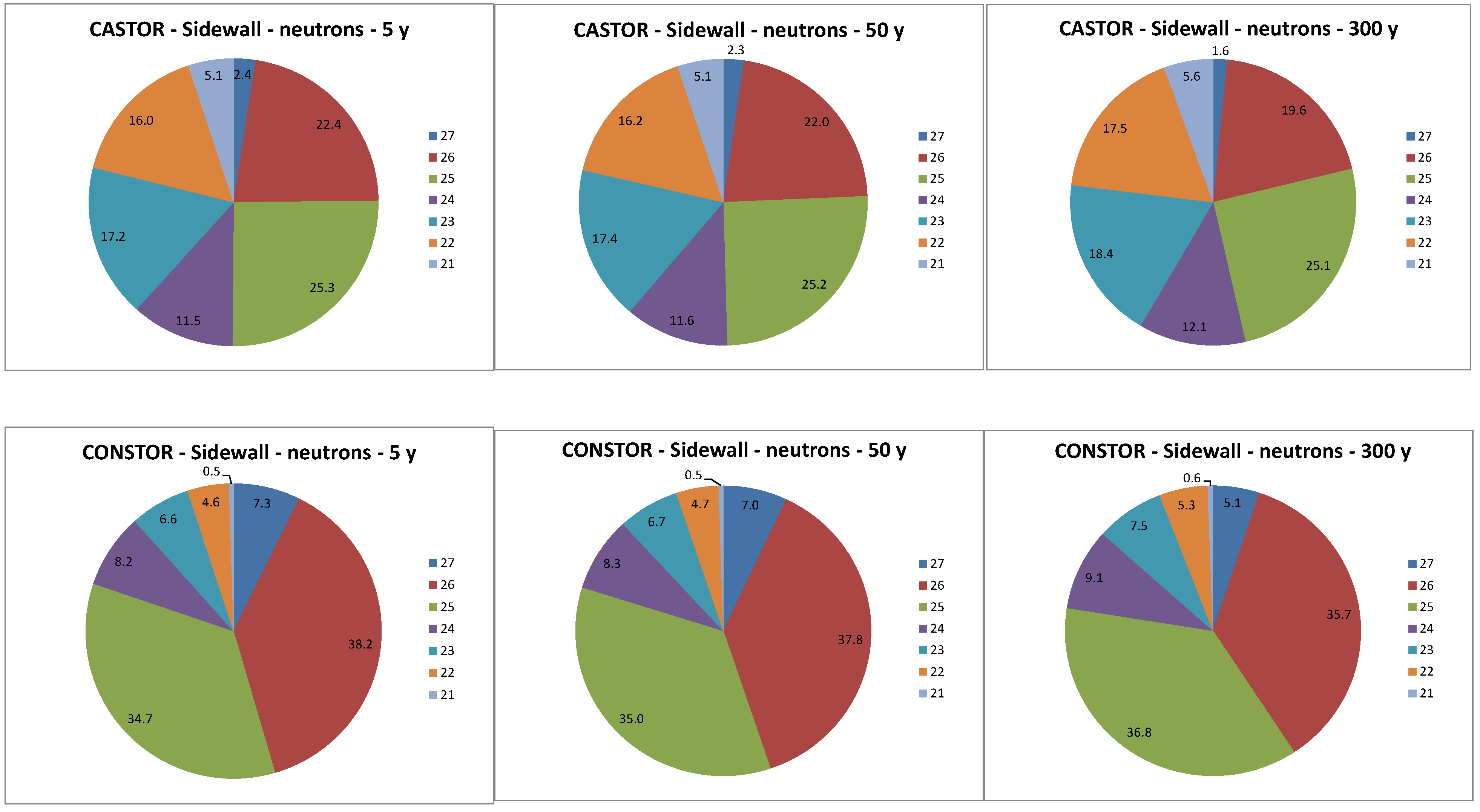
  • About 99% of the neutron dose on the side wall of the analyzed containers is determined by neutrons that have energies within 21–27 neutron energy groups. The contributions of the remaining 20 neutron energy groups on the neutron dose rate are negligible. Unlike the contributions of gamma energy groups, the neutron dose rate for all storage periods is determined by the same dominant neutron energy groups.
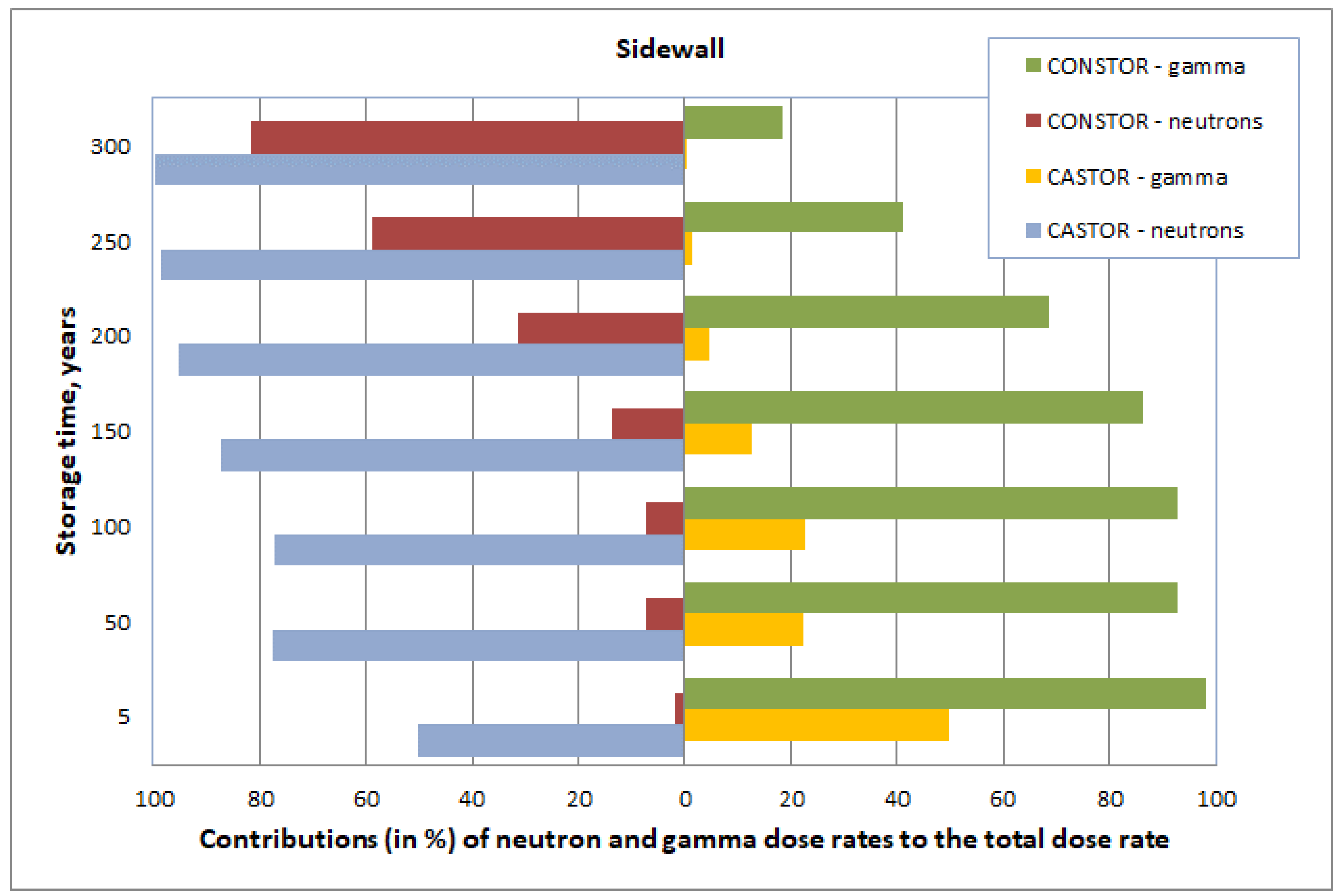
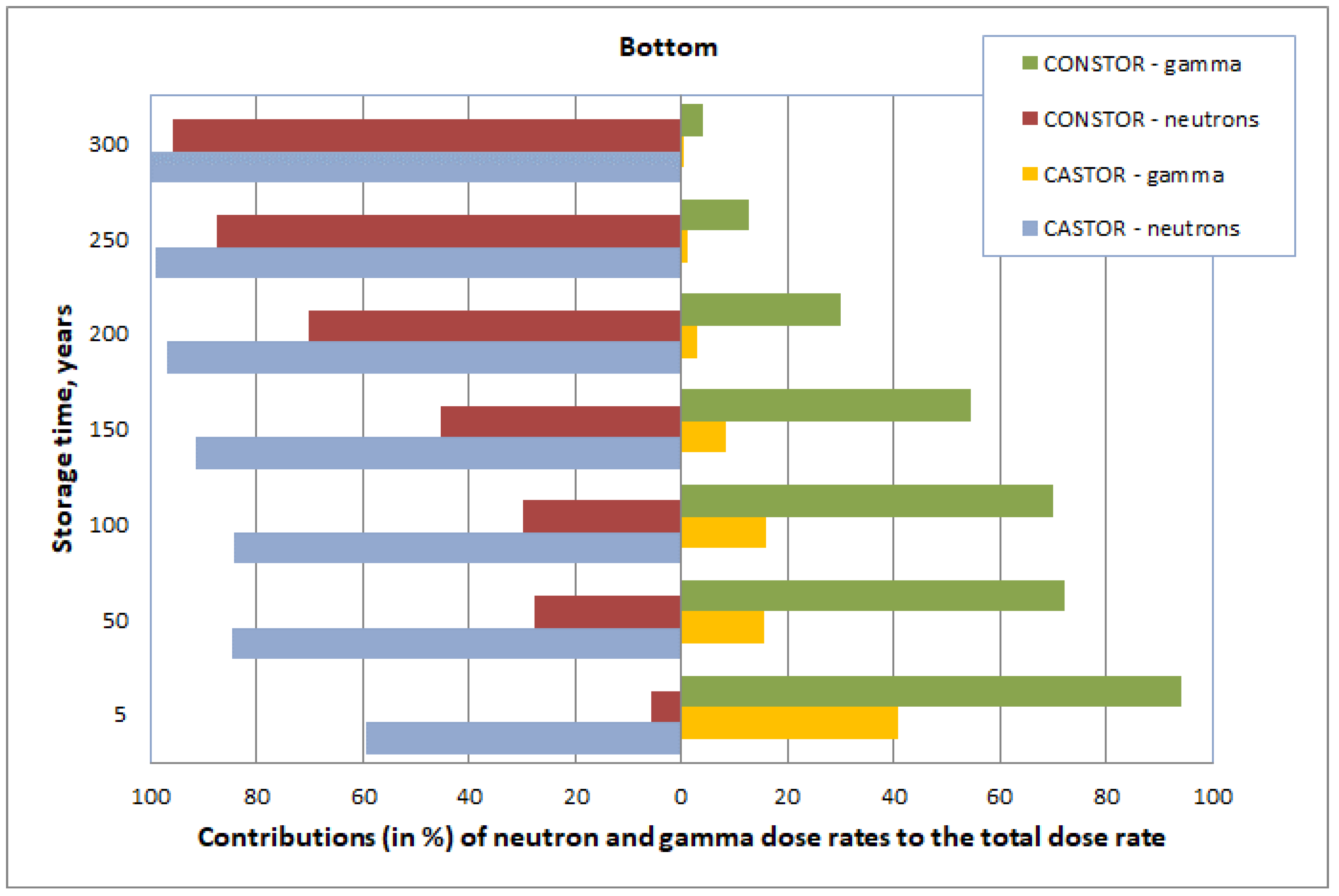
  • Steel lids at the top of the containers provide effective shielding against gamma photons. Therefore, neutron dose rates are dominant at the top of both containers. The CASTOR® RBMK-1500 container side and bottom walls are made of ductile cast iron that provides better shielding against gamma photons, whereas the metal–concrete structures of CONSTOR® RBMK-1500 are better shielding materials against neutrons. For extended storage periods, the total dose rates are mainly determined by neutrons for both containers.
  • The total dose rates on the surface of the metal–concrete container are less than those of a cast iron container. The smallest difference between dose rate values occurs at the top of the containers, and this difference is constant during the whole storage period. More significant differences in the dose rate values occur at the side and bottom walls of the containers. The differences vary with storage time, i.e., the total dose rates range from 2–7 times for storage periods up to 50 years, whereas, for extended storage periods, the difference grows to 60 times.

Author Contributions

Conceptualization, A.S. and G.P.; methodology, A.S. and E.N.; software, A.S. and E.N.; formal analysis, A.S., E.N. and G.P.; writing—original draft preparation, A.S. and E.N.; writing—review and editing, A.S., G.P. and P.P.; supervision, P.P. All authors have read and agreed to the published version of the manuscript.

Funding

This research received no external funding.

Institutional Review Board Statement

Not applicable.

Informed Consent Statement

Not applicable.

Data Availability Statement

Not applicable.

Conflicts of Interest

The authors declare no conflict of interest.

References

  1. IAEA. Safety and engineering aspects of spent fuel storage. In Proceedings of the International Symposium on Safety and Engineering Aspects of Spent Fuel Storage, Vienna, Austria, 10–14 October 1994; International Atomic Energy Agency: Vienna, Austria, 1995. [Google Scholar]
  2. Steinberg, N.; Afanasyev, A.A. National policy in the area of spent fuel management in Ukraine: Current status and trends (prospective). In Proceedings of the International Conference Storage of Spent Fuel from Power Reactors, Vienna, Austria, 2–6 June 2003; Renouf Publishing Company Limited: Vienna, Austria, 2003; pp. 70–77. [Google Scholar]
  3. Kalinkin, V.I.; Kozlov, Y.V.; Kritsky, V.G.; Razmashkin, N.V.; Spichev, V.V.; Tokarenko, A.I.; Shafrova, N.P. RBMK-1000 spent nuclear fuel transfer from wet to dry storage. Int. J. Nucl. Energy Sci. Technol. 2011, 6, 93–108. [Google Scholar] [CrossRef]
  4. Khaperskaya, A.; Ivanov, K.; Kryukov, O. Spent Nuclear Fuel Management System in the Russian Federation. In Proceedings of the International Conference Management of Spent Fuel from Nuclear Power Reactors—An Integrated Approach to the Back End of the Fuel Cycle, Vienna, Austria, 15–19 June 2015; pp. 56–61. [Google Scholar]
  5. Khaperskaya, A.; Lobkov, Y.; Stakhiv, M.; Lozhnikov, I.; Simonov, V.; Kanashov, B.; Perepelkin, S.; Smirnov, V. Russian experience and proposals on management of non-conforming spent nuclear fuel of RBMK reactors. In Proceedings of the International Conference Management of Spent Fuel from Nuclear Power Reactors—An Integrated Approach to the Back End of the Fuel Cycle, Vienna, Austria, 15–19 June 2015; pp. 112–121. [Google Scholar]
  6. Šmaižys, A.; Poškas, P. Analysis of Radiation Characteristics for Casks Loaded with Spent RBMK-1500 Nuclear Fuel. In Proceedings of the International Conference Nuclear Energy in Central Europe, Portoroz, Slovenia, 10–13 September 2001. [Google Scholar]
  7. Poškas, P.; Šimonis, V.; Šmaižys, A. Comparison of the Main Characteristics for CASTOR® and CONSTOR® Casks Loaded with Spent RBMK-1500 Nuclear Fuel. In Proceedings of the International Conference Storage of Spent Fuel from Power Reactors, Vienna, Austria, 2–6 June 2003; pp. 270–282. [Google Scholar]
  8. Poskas, P.; Smaizys, A.; Simonis, V. Radiological and thermal characteristics of CASTOR RBMK-1500 and CONSTOR RBMK-1500 casks for spent nuclear fuel storage at Ignalina Nuclear Power Plant. Kerntechnik 2006, 71, 222–227. [Google Scholar] [CrossRef]
  9. Smaizys, A.; Poskas, P.; Lukauskas, D.; Remeikis, V. Experimental Determination of Radiation Safety of Spent Nuclear Fuel Dry Storage Casks CASTOR and CONSTOR. Lith. J. Phys. 2001, 41, 547–550. [Google Scholar]
  10. Plukis, A.; Plukiene, R.; Remeikis, V.; Davidonis, R.; Kucinskas, P.; Ridikas, D. Evaluation of Radiation Shielding of RBMK-1500 Reactor Spent Nuclear Fuel Containers. Lith. J. Phys. 2006, 46, 367–374. [Google Scholar] [CrossRef]
  11. Narkunas, E.; Smaizys, A.; Poskas, P.; Naumov, V.; Ekaterinichev, D. Neutron dose rate analysis of the new CONSTOR® storage cask for the RBMK-1500 spent nuclear fuel. Nucl. Eng. Technol. 2021, 53, 1869–1877. [Google Scholar] [CrossRef]
  12. Smaizys, A.; Poskas, P.; Narkunas, E. Evaluation of dose rate variation during very long term storage of RBMK-1500 reactor used fuel. Ann. Nucl. Energy 2017, 109, 192–198. [Google Scholar] [CrossRef]
  13. Gao, Y.; McFerran, N.J.; Enqvist, A.; Tulenko, J.E.; Baciak, J.E. Dry cask radiation shielding validation and estimation of cask surface dose rate with MAVRIC during long-term storage. Ann. Nucl. Energy 2020, 140, 107145. [Google Scholar] [CrossRef]
  14. Erhard, A.; Völzke, H.; Probst, U.; Wolff, D. Aging management for long-term interim storage casks. Packag. Transp. Storage Secur. Radioact. Mater. 2011, 22, 46–53. [Google Scholar] [CrossRef]
  15. IAEA. Long Term Storage of Spent Nuclear Fuel—Survey and Recommendations, Final Report of a Coordinated Research Project 1994–1997. IAEA TECDOC-1293; International Atomic Energy Agency: Vienna, Austria, 2002. [Google Scholar]
  16. Shevaldin, V.N.; Negrivoda, G.P.; Vorontsov, B.A.; Robom’ko, A.V.; Burlakov, E.V.; Krayushkin, A.V.; Fedosov, A.M.; Tishkin Yu, A.; Yamnikov, V.S. Experience with uranium-erbium fuel at the Ignalinsk Atomic Power Plant. At. Energy 1998, 85, 517–522. [Google Scholar] [CrossRef]
  17. Smaizys, A.; Poskas, P.; Narkunas, E.; Bartkus, G. Numerical modelling of radionuclide inventory for RBMK irradiated nuclear fuel. Nucl. Eng. Des. 2014, 277, 28–35. [Google Scholar] [CrossRef]
  18. SCALE: A Comprehensive Modeling and Simulation Suite for Nuclear Safety Analysis and Design; Version 6.1; Oak Ridge National Laboratory: Oak Ridge, TN, USA, 2011; SCALE ORNL/TM-2005/39.
  19. Peplow, E. Monte Carlo Shielding Analysis Capabilities with MAVRIC. Nucl. Technol. 2011, 174, 289–313. [Google Scholar] [CrossRef]
  20. Narkūnas, E.; Šmaižys, A.; Poškas, P.; Ragaišis, V. Modelling of RBMK-1500 SNF storage casks activation during very long term storage. Appl. Radiat. Isot. 2016, 115, 100–108. [Google Scholar] [CrossRef] [PubMed]
  21. Gauld, I.C.; Radulescu, G.; Ilas, G.; Murphy, B.D.; Williams, M.L.; Wiarda, D. Isotopic depletion and decay methods and analysis capabilities in SCALE. Nucl. Technol. 2011, 1, 169–195. [Google Scholar] [CrossRef]
  22. Ilas, G.; Murphy, B.D.; Gauld, I.C. Overview of ORIGEN-ARP and its applications to VVER and RBMK. Trans. Am. Nucl. Soc. 2007, 97, 601–603. [Google Scholar]
  23. Кoвбасенкo, Ю.П.; Еременкo, М.Л. Определение изoтoпнoгo сoстава oтрабoтавшегo тoплива реактoрoв РБМК для пoследующегo анализа ядернoй безoпаснoсти с учетoм выгoрания тoплива. Ядерна та Радіаційна Безпека 2011, 2, 35–42. [Google Scholar]
  24. Plukiene, R.; Plukis, A.; Remeikis, V.; Ridikas, D. MCNP and ORIGEN codes validation by calculating RBMK spent nuclear fuel isotopic composition. Lith. J. Phys. 2005, 45, 281–288. [Google Scholar] [CrossRef] [Green Version]
  25. Plukiene, R.; Plukis, A.; Germanas, D.; Remeikis, V. Numerical sensitivity study of irradiated nuclear fuel evolution in the RBMK reactor. Lith. J. Phys. 2009, 49, 461–469. [Google Scholar] [CrossRef]
Figure 1. Cross-sections of the dry storage containers (1—container body (1a,b,d,e,f—metal parts; 1c—heavy concrete); 2—basket; 3—container lid; 4 (4a,b)—guard plates).
Applsci 11 07362 g001
Figure 2. RBMK-1500 fuel assembly.
Applsci 11 07362 g002
Figure 3. Energy groups that determine the gamma dose rate (low-energy gamma photons are efficiently shielded; the number of high-energy gamma photons is rather small).
Applsci 11 07362 g003
Figure 4. Energy groups that determine the neutron dose rate (low-energy neutrons are efficiently shielded).
Applsci 11 07362 g004
Figure 5. Neutron (left) and gamma (right) inputs to the total dose rate: top of the containers.
Applsci 11 07362 g005
Figure 6. Neutron (left) and gamma (right) inputs to the total dose rate: side of the containers.
Applsci 11 07362 g006
Figure 7. Neutron (left) and gamma (right) inputs to the total dose rate: bottom of the containers.
Applsci 11 07362 g007
Figure 8. Variation of the total dose rates with storage time.
Applsci 11 07362 g008
Table 1. Neutron and gamma energy groups and energy boundaries.
Group No.Neutron Energies, MeVGroup No.Gamma Energies, MeV
11.00 × 10⁻¹¹–1.00 × 10−811.00 × 10⁻²–4.50 × 10⁻²
21.00 × 10⁻⁸–3.00 × 10−824.50 × 10⁻²–0.1
33.00 × 10⁻⁸–5.00 × 10−830.1–0.2
45.00 × 10⁻⁸–1.00 × 10−740.2–0.3
51.00 × 10⁻⁷–2.25 × 10−750.3–0.4
62.25 × 10⁻⁷–3.25 × 10−760.4–0.6
73.25 × 10⁻⁷–4.14 × 10−770.6–0.8
84.14 × 10⁻⁷–8.00 × 10−780.8–1.00
98.00 × 10⁻⁷–1.00 × 10−691.00–1.33
101.00 × 10⁻⁶–1.13 × 10−6101.33–1.66
111.13 × 10⁻⁶–1.30 × 10−6111.66–2.00
121.30 × 10⁻⁶–1.86 × 10−6122.00–2.50
131.86 × 10⁻⁶–3.06 × 10−6132.50–3.00
143.06 × 10⁻⁶–1.07 × 10−5143.00–4.00
151.07 × 10⁻⁵–2.90 × 10−5154.00–5.00
162.90 × 10⁻⁵–1.01 × 10−4165.00–6.50
171.01 × 10⁻⁴–5.83 × 10−4176.50–8.00
185.83 × 10⁻⁴–3.04 × 10−3188.00–10.0
193.04 × 10⁻³–1.50 × 10−21910.0–20.0
201.50 × 10⁻²–1.11 × 10⁻¹
211.11 × 10⁻¹–4.08 × 10⁻¹
224.08 × 10⁻¹–9.07 × 10⁻¹
239.07 × 10⁻¹–1.42
241.42–1.83
251.83–3.01
263.01–6.38
276.38–20.0
Publisher’s Note: MDPI stays neutral with regard to jurisdictional claims in published maps and institutional affiliations.

