
Computer-Generated Hologram Based on Reference Light Multiplexing for Holographic Display

Abstract
:1. Introduction
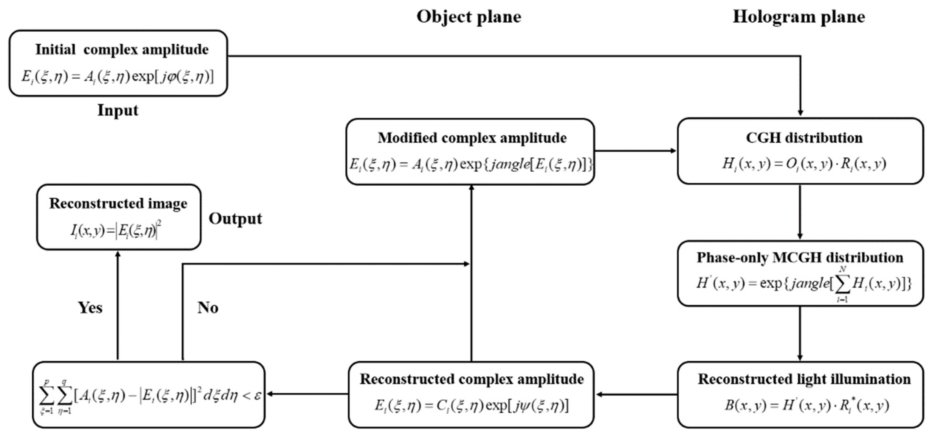
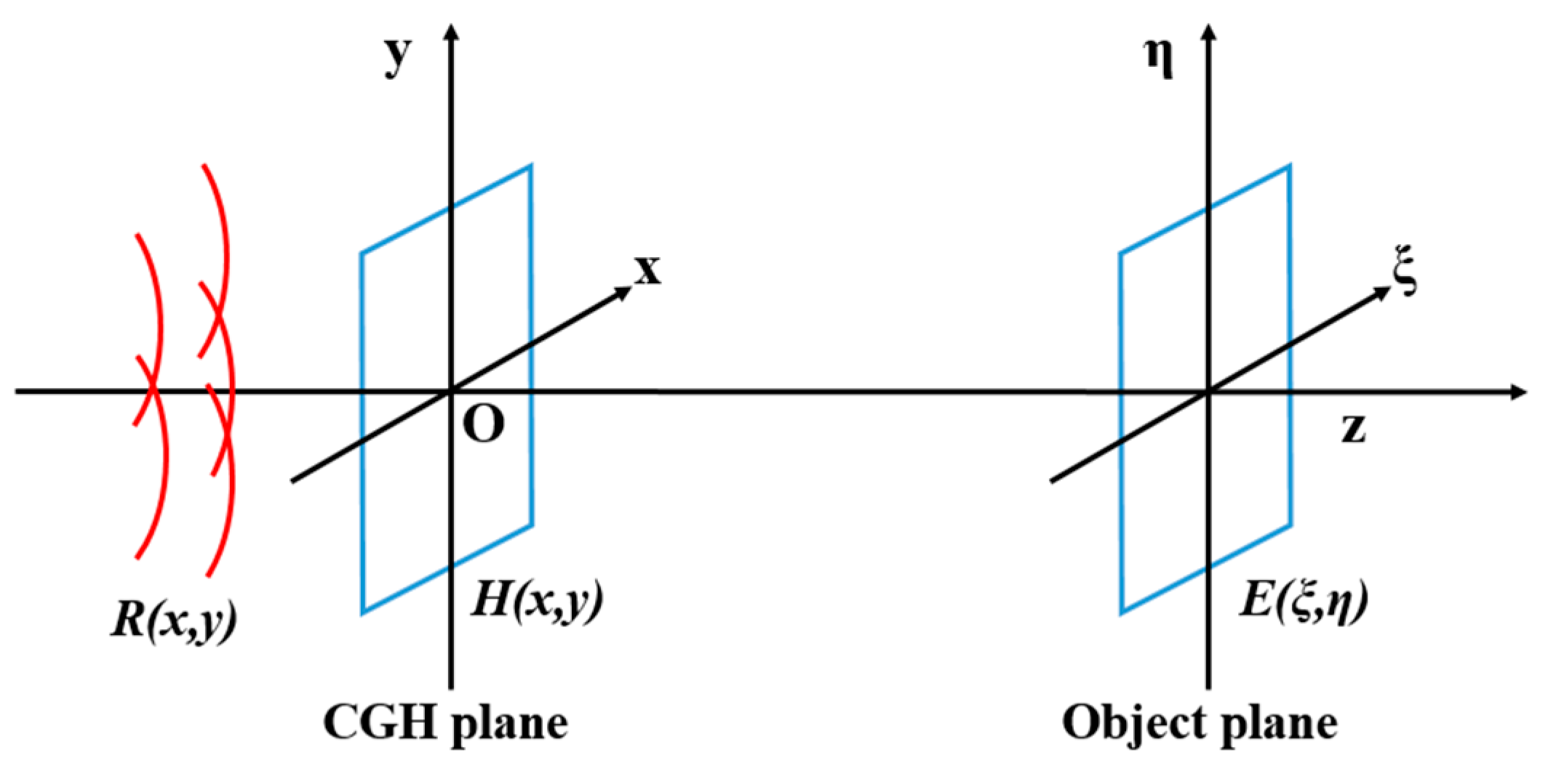
2. Principles and Methods
- Acquire target complex amplitude distribution
- 2.
- Propagate to CGH plane
- 3.
- Define reference light wave
- 4.
- Record CGH
- 5.
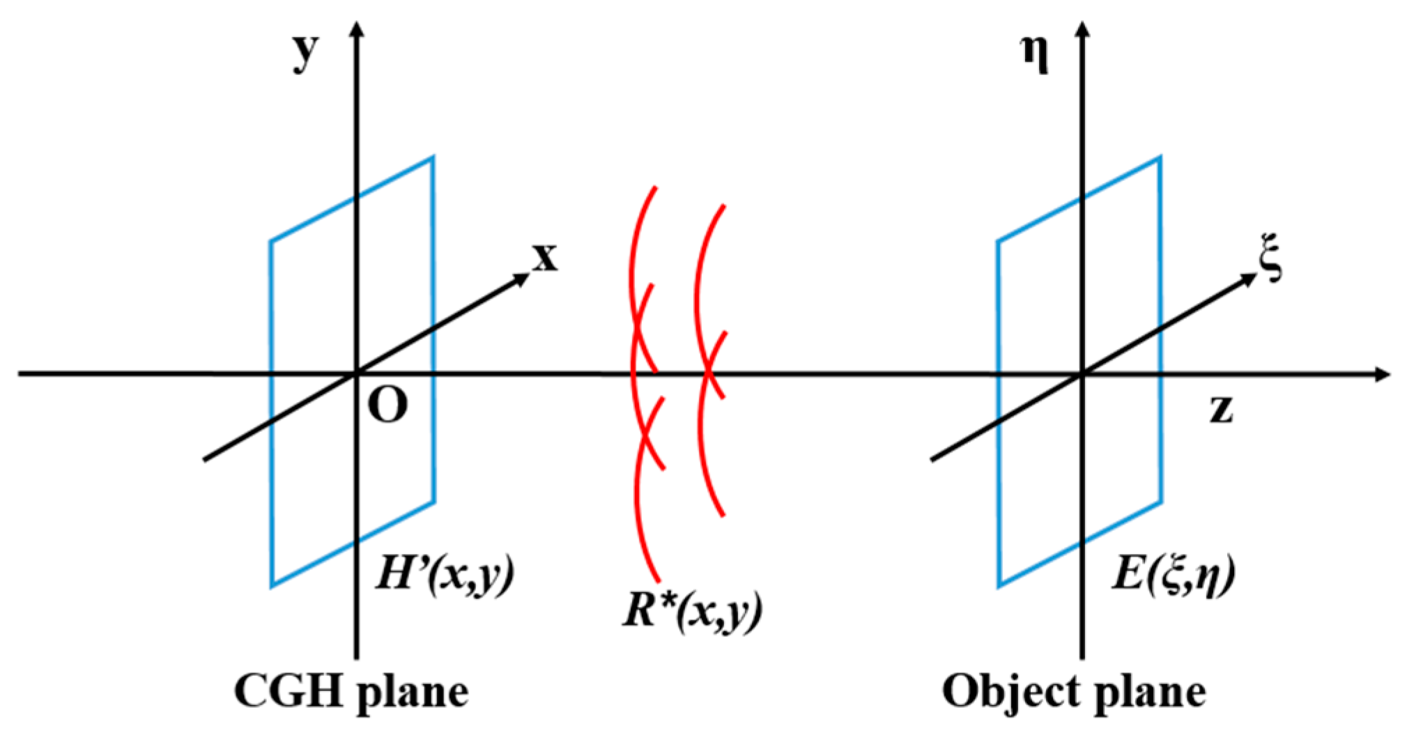
- Generate MCGH
- 6.
- Reconstruct image
- 7.
- Decide to stop the iteration process
- 8.
- Modify target distribution
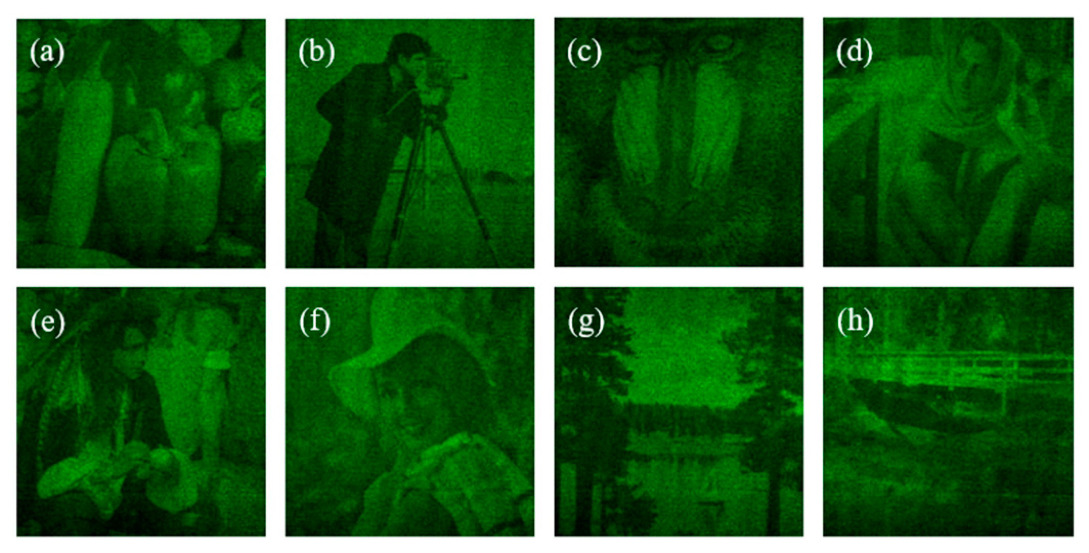
3. Numerical Simulation and Emulation
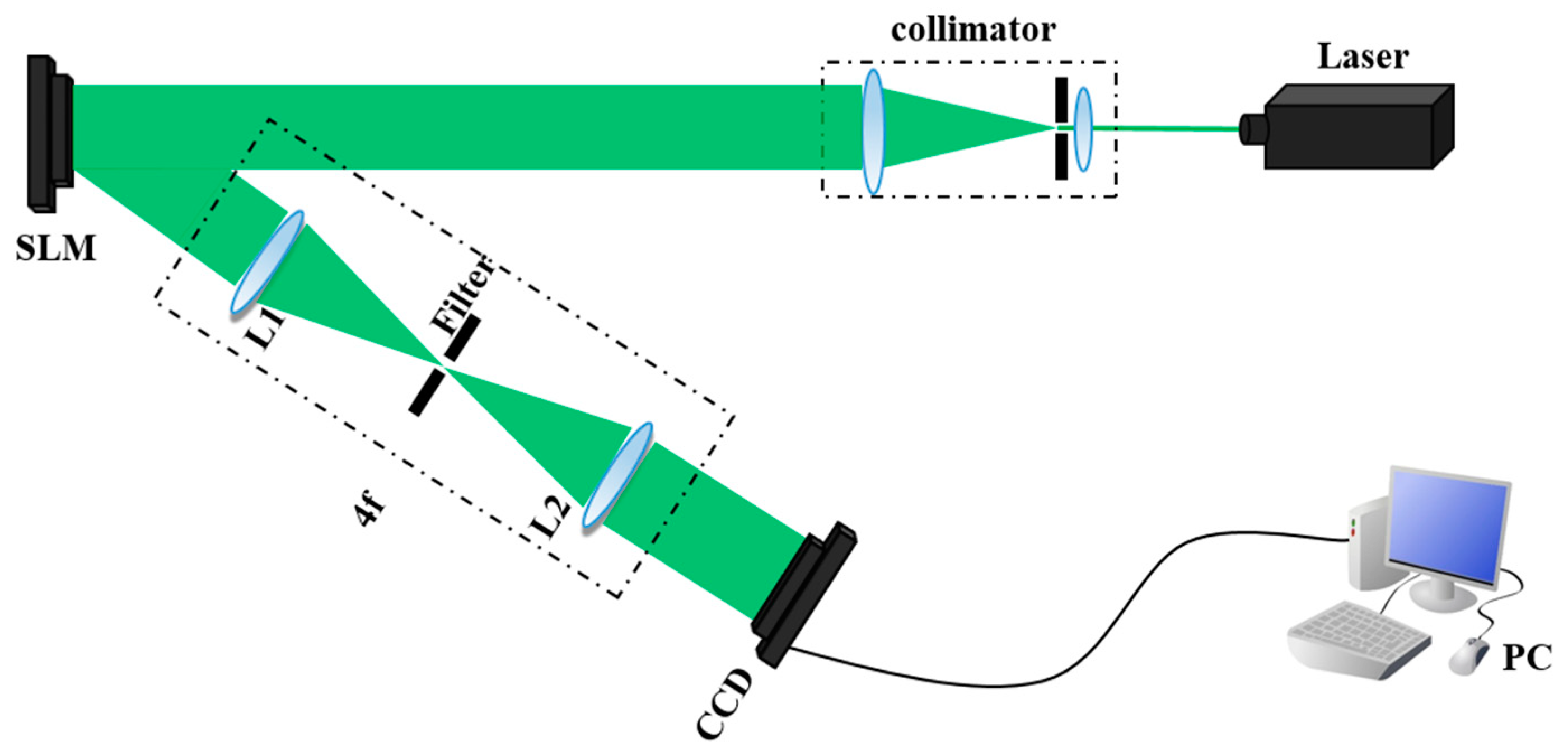
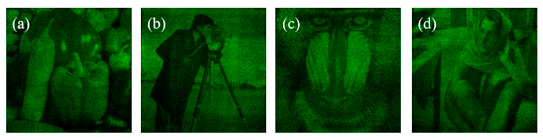
4. Optical Experiments
5. Conclusions
Author Contributions
Funding
Conflicts of Interest
References
- Pan, Y.; Liu, J.; Li, X.; Wang, Y. A review of dynamic holographic 3D display: Algorithms, devices, and systems. IEEE Trans. Ind. Inform. 2015, 12, 1599–1610. [Google Scholar] [CrossRef]
- Shi, L.; Li, B.; Kim, C.; Kellnhofer, P.; Matusiket, W. Towards real-time photorealistic 3D holography with deep neural networks. Nature 2021, 591, 234–239. [Google Scholar] [CrossRef] [PubMed]
- Pi, D.; Liu, J.; Kang, R.; Zhang, Z.; Han, Y. Reducing the memory usage of computer-generated hologram calculation using accurate high-compressed look-up-table method in color 3D holographic display. Opt. Express 2019, 27, 28410–28422. [Google Scholar] [CrossRef]
- Zhang, H.; Zhao, Y.; Cao, L.; Jin, G. Fully computed holographic stereogram based algorithm for computergenerated holograms with accurate depth cues. Opt. Express 2015, 23, 3901–3913. [Google Scholar] [CrossRef]
- Zhang, H.; Cao, L.; Jin, G. Three-dimensional computer-generated hologram with Fourier domain segmentation. Opt. Express 2019, 27, 11689–11697. [Google Scholar] [CrossRef]
- Pi, D.; Liu, J.; Kang, R.; Han, Y.; Yu, S. Accelerating calculation method for curved computer-generated hologram using look-up table in holographic display. Opt. Commun. 2021, 485, 126750. [Google Scholar] [CrossRef]
- Matoba, O.; Javidi, B. Encrypted optical memory system using three-dimensional keys in the Fresnel domain. Opt. Lett. 1999, 24, 762–764. [Google Scholar] [CrossRef]
- Situ, G.; Zhang, J. Multiple-image encryption by wavelength multiplexing. Opt. Lett. 2005, 30, 1306–1308. [Google Scholar] [CrossRef] [PubMed]
- Situ, G.; Zhang, J. Position multiplexing for multiple-image encryption. J. Opt. A Pure Appl. Opt. 2006, 8, 391–397. [Google Scholar] [CrossRef]
- Mueller, J.P.B.; Rubin, N.A.; Devlin, R.C.; Groever, B.; Capasso, F. Metasurface polarization optics: Independent phase control of arbitrary orthogonal states of polarization. Phys. Rev. Lett. 2017, 118, 113901. [Google Scholar] [CrossRef] [PubMed] [Green Version]
- Wen, D.; Yue, F.; Li, G.; Zheng, G.; Chan, K.; Chen, S.; Chen, M.; Li, K.F.; Wong, P.W.H.; Cheah, K.W.; et al. Helicity multiplexed broadband metasurface holograms. Nat. Commun. 2015, 6, 8241. [Google Scholar] [CrossRef]
- Li, X.; Chen, L.; Li, Y.; Zhang, X.; Pu, M.; Zhao, Z.; Ma, X.; Wang, Y.; Hong, M.; Luo, X. Multicolor 3D meta-holography by broadband plasmonic modulation. Sci. Adv. 2016, 2, e1601102. [Google Scholar] [CrossRef] [PubMed] [Green Version]
- Kamali, S.M.; Arbabi, E.; Arbabi, A.; Horie, Y.; Faraji-Dana, M.; Faraon, A. Angle-multiplexed metasurfaces: Encoding independent wavefronts in a single metasurface under different illumination angles. Phys. Rev. X 2017, 7, 041056. [Google Scholar] [CrossRef] [Green Version]
- Fang, X.; Ren, H.; Gu, M. Orbital angular momentum holography for high-security encryption. Nat. Photonics 2020, 14, 102–108. [Google Scholar] [CrossRef]
- Pi, D.; Liu, J.; Han, Y.; Khalid, A.U.R.; Yu, S. Simple and effective calculation method for computer-generated hologram based on non-uniform sampling using look-up-table. Opt. Express 2019, 27, 37337–37348. [Google Scholar] [CrossRef]
- Pi, D.; Liu, J.; Han, Y.; Yu, S.; Xiang, N. Acceleration of computer-generated hologram using wavefront-recording plane and look-up table in three-dimensional holographic display. Opt. Express 2020, 28, 9833–9841. [Google Scholar] [CrossRef] [PubMed]
- Mishina, T.; Okano, F.; Yuyama, I. Time-alternating method based on single-sideband holography with half-zone-plate processing for the enlargement of viewing zones. Appl. Opt. 1999, 38, 3703–3713. [Google Scholar] [CrossRef]
- Jia, J.; Wang, Y.; Liu, J.; Li, X.; Pan, Y.; Sun, Z.; Zhang, B.; Zhao, Q.; Jiang, W. Reducing the memory usage for effective computer-generated hologram calculation using compressed look-up table in full-color holographic display. Appl. Opt. 2013, 52, 1404–1412. [Google Scholar] [CrossRef] [PubMed]
- Hahn, J.; Kim, H.; Lim, Y.; Park, G.; Lee, B. Wide viewing angle dynamic holographic stereogram with a curved array of spatial light modulators. Opt. Express 2008, 16, 12372–12386. [Google Scholar] [CrossRef]
- Kozacki, T.; Kujawińska, M.; Finke, G.; Hennelly, B.; Pandey, N. Extended viewing angle holographic display system with tilted SLMs in a circular configuration. Appl. Opt. 2012, 51, 1771–1780. [Google Scholar] [CrossRef] [Green Version]
- Makowski, M.; Sypek, M.; Kolodziejczyk, A. Colorful reconstructions from a thin multi-plane phase hologram. Opt. Express 2008, 16, 11618–11623. [Google Scholar] [CrossRef] [PubMed]
- Shimobaba, T.; Takahashi, T.; Masuda, N.; Ito, T. Numerical study of color holographic projection using space-division method. Opt. Express 2011, 19, 10287–10292. [Google Scholar] [CrossRef]
- Ito, T.; Okano, K. Color electroholography by three colored reference lights simultaneously incident upon one hologram panel. Opt. Express 2004, 12, 4320–4325. [Google Scholar] [CrossRef] [PubMed] [Green Version]
- Kozacki, T.; Chlipala, M. Color holographic display with white light LED source and single phase only SLM. Opt. Express 2016, 24, 2189–2199. [Google Scholar] [CrossRef] [PubMed]
- Lin, S.; Kim, E. Single SLM full-color holographic 3-D display based on sampling and selective frequency-filtering methods. Opt. Express 2017, 25, 11389–11404. [Google Scholar] [CrossRef] [PubMed]
- Lin, S.; Cao, H.; Kim, E. Single SLM full-color holographic three-dimensional video display based on image and frequency-shift multiplexing. Opt. Express 2019, 27, 15926–15942. [Google Scholar] [CrossRef] [PubMed]
- Makey, G.; Yavuz, Ö.; Kesim, D.K.; Turnalı, A.; Elahi, P.; Ilday, S.; Tokel, O.; Ilday, F.Ö. Breaking crosstalk limits to dynamic holography using orthogonality of high-dimensional random vectors. Nat. Photonics 2019, 13, 251–256. [Google Scholar] [CrossRef] [PubMed]
- Velez-Zea, A.; Torroba, R. Mixed constraint in global and sequential hologram generation. Appl. Opt. 2021, 60, 1888–1895. [Google Scholar] [CrossRef] [PubMed]
- Kang, R.; Liu, J.; Xue, G.; Li, X.; Pi, D. Curved multiplexing computer-generated hologram for 3D holographic display. Opt. Express 2019, 27, 14369–14380. [Google Scholar] [CrossRef]
- Liu, C.; Jin, F.; Wu, Y.; Wang, J.; Chen, C. Two-dimensional angle multiplexing by segmented spherical holography. Appl. Opt. 2021, 60, 155–161. [Google Scholar] [CrossRef]
- Pi, D.; Liu, J.; Duan, X.; Han, Y.; He, P. Design methods to generate a computer hologram for improving image quality. Appl. Opt. 2018, 57, 2720–2726. [Google Scholar] [CrossRef] [PubMed]
- Chen, L.; Zhang, H.; Cao, L.; Jin, G. Non-iterative phase hologram generation with optimized phase modulation. Opt. Express 2020, 28, 11380–11392. [Google Scholar] [CrossRef] [PubMed]
- Mendoza-Yero, O.; Mínguez-Vega, G.; Lancis, J. Encoding complex felds by using a phase-only optical element. Opt. Lett. 2014, 39, 1740–1743. [Google Scholar] [CrossRef] [PubMed] [Green Version]
- Qi, Y.J.; Chang, C.L.; Xia, J. Speckleless holographic display by complex modulation based on double-phase method. Opt. Express 2016, 24, 30368. [Google Scholar] [CrossRef] [PubMed]
- Sui, X.M.; He, Z.H.; Zhang, H.; Cao, L.C.; Chu, D.P.; Jin, G.F. Spatiotemporal double-phase hologram for complex-amplitude holographic displays. Chin. Opt. Lett. 2020, 18, 100901. [Google Scholar] [CrossRef]
- Sui, X.; He, Z.; Jin, G.; Chu, D.; Cao, L. Band-limited double-phase method for enhancing image sharpness in complex modulated computer-generated holograms. Opt. Express 2021, 29, 2597–2612. [Google Scholar] [CrossRef]
- Reichelt, S.; Häussler, R.; Fütterer, G.; Leister, N.; Kato, H.; Usukura, N.; Kanbayashi, Y. Full-range, complex spatial light modulator for real-time holography. Opt. Lett. 2012, 37, 1955–1957. [Google Scholar] [CrossRef]
- Goorden, S.A.; Bertolotti, J.; Mosk, A.P. Superpixel-based spatial amplitude and phase modulation using a digital micromirror device. Opt. Express 2014, 22, 17999–18009. [Google Scholar] [CrossRef] [Green Version]
- Chang, C.; Xia, J.; Yang, L.; Lei, W.; Yang, Z.; Chen, J. Speckle-suppressed phase-only holographic threedimensional display based on double-constraint Gerchberg-Saxton algorithm. Appl. Opt. 2015, 54, 6994–7001. [Google Scholar] [CrossRef]
- Liu, J.P.; Hsieh, W.Y.; Poon, T.C.; Tsang, P. Complex Fresnel hologram display using a single SLM. Appl. Opt. 2011, 50, H128–H135. [Google Scholar] [CrossRef] [Green Version]
- Li, X.; Liu, J.; Jia, J.; Pan, Y.; Wang, Y. 3D dynamic holographic display by modulating complex amplitude experimentally. Opt. Express 2013, 21, 20577–20587. [Google Scholar] [CrossRef] [PubMed]
- Gerchberg, R.W.; Saxton, W.O. A practical algorithm for the determination of phase from image and diffraction plane pictures. Optik 1972, 35, 237–246. [Google Scholar]
- Fienup, J.R. Reconstruction of an object from the modulus of its Fourier transform. Opt. Lett. 1978, 3, 27–29. [Google Scholar] [CrossRef] [PubMed]
- Zhang, H.; Xie, J.; Liu, J.; Wang, Y. Elimination of a zero-order beam induced by a pixelated spatial light modulator for holographic projection. Appl. Opt. 2009, 48, 5834–5841. [Google Scholar] [CrossRef] [PubMed]


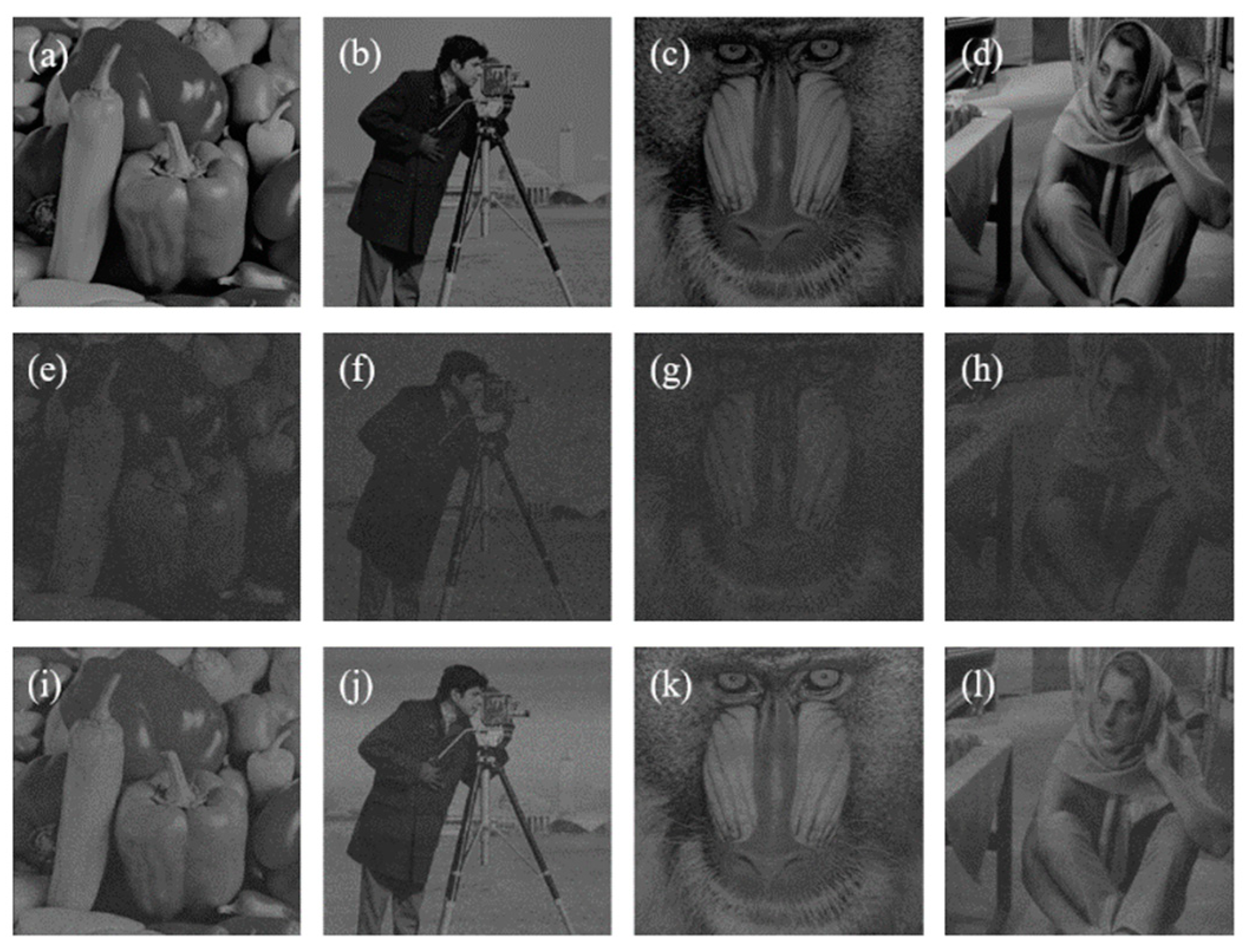
| Iteration | Image | RMSE | SC |
|---|---|---|---|
| 0 | pepper | 0.325 | 0.513 |
| cameraman | 0.337 | 0.518 | |
| baboon | 0.352 | 0.536 | |
| woman | 0.303 | 0.516 | |
| 20 | pepper | 0.159 | 0.288 |
| cameraman | 0.168 | 0.301 | |
| baboon | 0.153 | 0.336 | |
| woman | 0.145 | 0.321 |
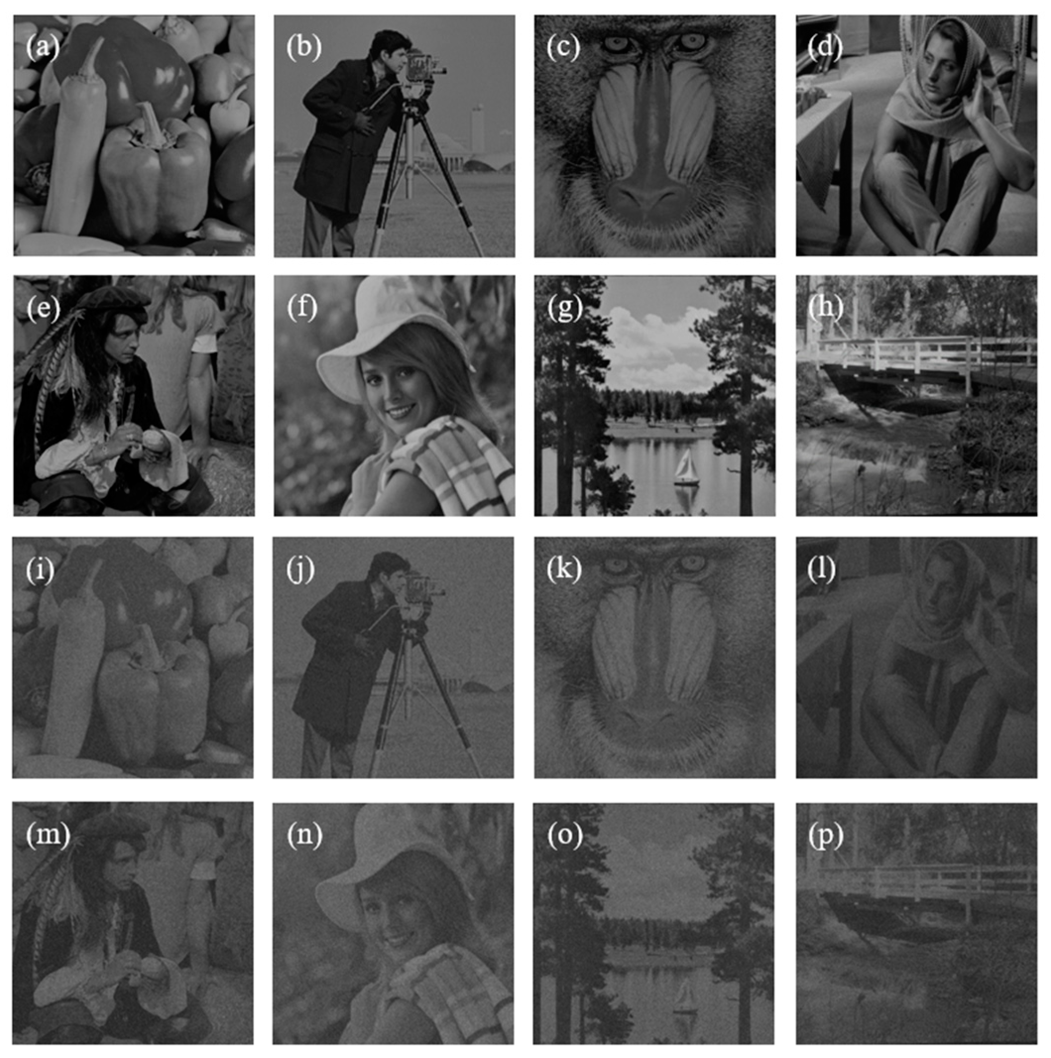
| Image | RMSE | SC |
|---|---|---|
| pepper | 0.232 | 0.367 |
| cameraman | 0.244 | 0.292 |
| baboon | 0.254 | 0.369 |
| woman | 0.221 | 0.345 |
| man | 0.234 | 0.353 |
| girl | 0.238 | 0.300 |
| sailboat | 0.248 | 0.351 |
| bridge | 0.236 | 0.322 |
| Image | RMSE | SC |
|---|---|---|
| pepper | 0.293 | 0.258 |
| cameraman | 0.322 | 0.296 |
| baboon | 0.294 | 0.244 |
| woman | 0.257 | 0.278 |
| Image | RMSE | SC |
|---|---|---|
| pepper | 0.337 | 0.244 |
| cameraman | 0.319 | 0.322 |
| baboon | 0.354 | 0.273 |
| woman | 0.292 | 0.317 |
| man | 0.349 | 0.249 |
| girl | 0.363 | 0.249 |
| sailboat | 0.364 | 0.314 |
| bridge | 0.317 | 0.298 |
Publisher’s Note: MDPI stays neutral with regard to jurisdictional claims in published maps and institutional affiliations. |
© 2021 by the authors. Licensee MDPI, Basel, Switzerland. This article is an open access article distributed under the terms and conditions of the Creative Commons Attribution (CC BY) license (https://creativecommons.org/licenses/by/4.0/).
Share and Cite
Pi, D.; Liu, J. Computer-Generated Hologram Based on Reference Light Multiplexing for Holographic Display. Appl. Sci. 2021, 11, 7199. https://doi.org/10.3390/app11167199
Pi D, Liu J. Computer-Generated Hologram Based on Reference Light Multiplexing for Holographic Display. Applied Sciences. 2021; 11(16):7199. https://doi.org/10.3390/app11167199
Chicago/Turabian StylePi, Dapu, and Juan Liu. 2021. "Computer-Generated Hologram Based on Reference Light Multiplexing for Holographic Display" Applied Sciences 11, no. 16: 7199. https://doi.org/10.3390/app11167199
APA StylePi, D., & Liu, J. (2021). Computer-Generated Hologram Based on Reference Light Multiplexing for Holographic Display. Applied Sciences, 11(16), 7199. https://doi.org/10.3390/app11167199