Article

Analytical Investigation on Torque of Three-Degree-of-Freedom Electromagnetic Actuator for Image Stabilization

1
Department of Mechanical Engineering, National Cheng Kung University, Tainan 70101, Taiwan
2
International Master Program on Intelligent Manufacturing, National Cheng Kung University, Tainan 70101, Taiwan
*
Author to whom correspondence should be addressed.
Appl. Sci. 2021, 11(15), 6872; https://doi.org/10.3390/app11156872
Submission received: 16 June 2021 / Revised: 23 July 2021 / Accepted: 24 July 2021 / Published: 26 July 2021
(This article belongs to the Special Issue Selected Papers from IMETI 2020)

Abstract

:

Featured Application

This study focuses on the design of a 3-DOF spherical motor for the camera module of the humanoid and autonomous systems. The proposed 3-DOF spherical motor has a wide application prospect in joints and eyeballs of the humanoid, unmanned aerial vehicles, autonomous cars, walking robots, and other fields.

Abstract

In keeping with consumers’ preferences for electromagnetic motors of ever smaller power consumption, it is necessary to improve the power efficiency of the electromagnetic motors used in unmanned aerial vehicles and robots without sacrificing their performance. Three-degree-of-freedom (3-DOF) spherical motors have been developed for these applications. Accordingly, this study modifies the 3-DOF spherical motor proposed by Hirata’s group in a previous study (Heya, A.; Hirata, K.; Niguchi, N., Dynamic modeling and control of three-degree-of-freedom electromagnetic actuator for image stabilization, IEEE Transactions on Magnetics 2018, 54, 8207905.) to accomplish a 3-DOF spherical motor for camera module with higher torque output in the large rotation angle. The main contribution of this study is to improve the static torque in the X- and Y-axes with an improved electromagnetic structure and a particular controlling strategy. In the structural design, eight symmetrical coils with specific coil combination are used instead of conventional four symmetrical coils. In this study, the development of the proposed 3-DOF spherical motor was constructed and verified by using a 3D finite-element method (3D FEM). The simulation results show that the proposed 3-DOF spherical motor has higher torque output in the large rotation angle when compared to the original 3-DOF spherical motor.

1. Introduction

With the increasing demand of industrial automation and robots around the world for a multi-degree-of-freedom (DOF) motion mechanism, a motion mode for motors has been developed from simple 1-DOF motion to a multi-DOF motion, and the application of humanoid is actively proceeding [1,2]. Conventionally, for joints and eyeballs of the humanoid, the multi-DOF systems are implemented with multiple motors to mimic the movement of human body [3,4]. Multi-DOF systems are devices that can set orientation and positioning of the object in any direction [5,6]. However, these systems have increasing weight and size. In recent years, various multi-DOF motors have been developed and designed to achieve the multi-axis or multi-DOF motion. These multi-DOF motors include 2-DOF motors [7,8,9,10,11,12,13], 3-DOF motors [14,15,16], 4-DOF motors [17], and 5-DOF motors [18] depending on their applications. For example, Dehel et al. presented a 2-DOF motor with an unlimited angular range [7]. Sakaidani et al. proposed a feedback control method for a 2-DOF motor [10]. Song et al. and Liu et al. proposed some novel 2-DOF motors for camera modules [8,9,11,12]. Kwon and Ro proposed accurate and rapid analysis and optimal design methods for 2-DOF motor [13]. Heya et al. proposed a novel 3-DOF linear oscillatory motor [16]. Chang et al. proposed a novel 4-DOF motor for laser beam stabilization [17]. In camera modules, several methods were proposed in order to improve the efficiency, such as compliant mechanism [9,15], chamfered edge magnet [11], L-shape coil [12,18], optimization [8,13], and so on. In addition, motors can be classified by shape, such as square and sphere [7,10,14]. According to the collecting information, the performance comparison list of the several kinds of 3-DOF motors is shown in Table 1. In this study, the voice coil type is selected due to its simple structure, high response, and high positioning accuracy.
Spherical motors are electric devices capable of achieving multiple DOF rotary motions in a single joint [19,20,21]. Spherical motors have several advantages, such as a compact structure, a flexible motion mode, no accumulation of motion bias, and a simple control method compared with conventional multi-DOF actuating systems that consist of several single-DOF motors [1,22,23]. Therefore, they have been actively developed and have a wide application prospect in joints and eyeballs of the humanoid, unmanned aerial vehicles, autonomous cars, walking robots, and other fields. For these autonomous systems, environment and space recognition is a crucial function. The image information of the environment and space is captured by using a camera module, while these autonomous systems are moving [24]. As a result, developing a camera module with multi-DOF spherical motors to mimic the movement of human eyeball is an important issue in a wide application of the humanoid and autonomous systems.
This study focuses on the design of a 3-DOF spherical motor for the camera module of the humanoid and autonomous systems. Hirata’s group proposed a novel 3-DOF spherical motor for image stabilization, and the dynamic characteristics were clarified through the electromagnetic field analysis using the 3D finite-element method (3D FEM) [25]. In keeping with consumers’ preferences for electromagnetic actuators of ever smaller power consumption, it is necessary to improve the power efficiency of the electromagnetic motors used in unmanned aerial vehicles and robots without sacrificing their performance. Accordingly, this study modifies the 3-DOF spherical motor proposed by Hirata’s group in a previous study [25] to accomplish a 3-DOF spherical motor for camera module with higher torque output in the large rotation angle. The main contribution of this study is to improve the static torque in the X- and Y-axes with an improved electromagnetic structure and a particular controlling strategy. In the structural design, eight symmetrical coils with specific coil combination are used instead of the conventional four symmetrical coils.

2. Design of Original 3-DOF Spherical Motor

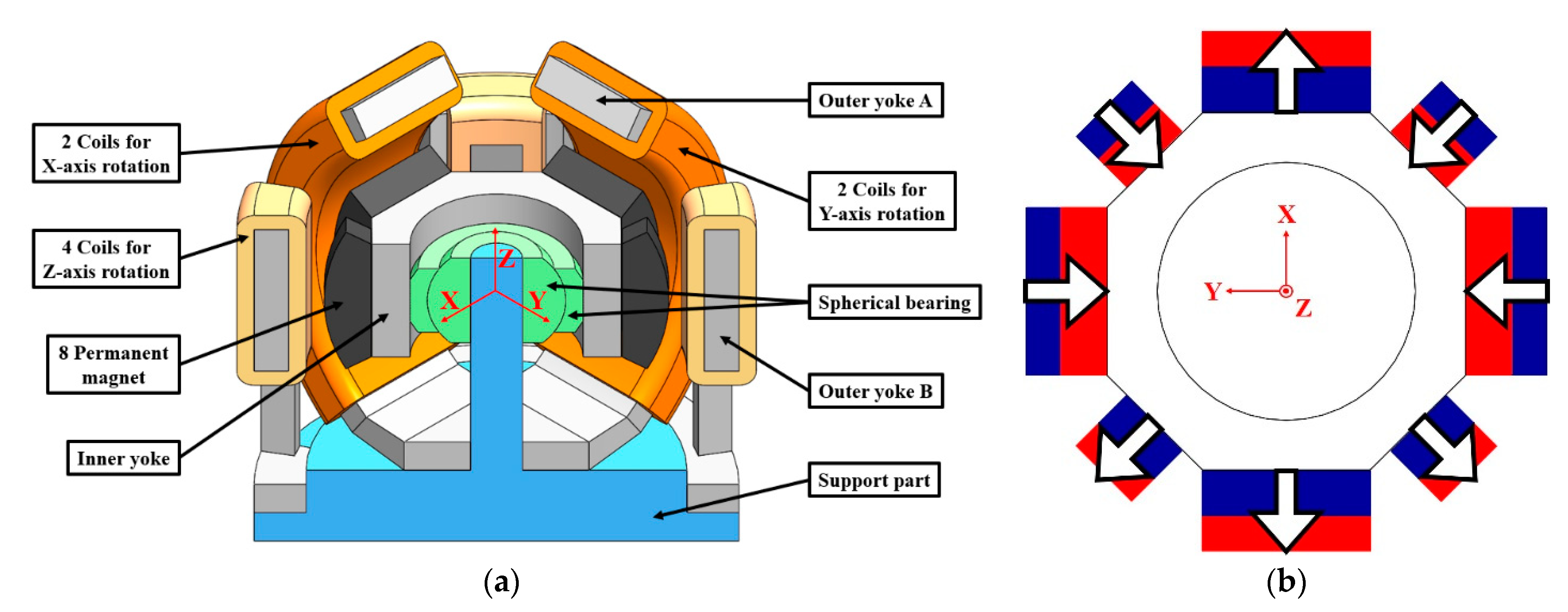
This section reviews the basic structure of the original 3-DOF spherical motor proposed by Hirata’s group in a previous study [25]. Its basic structure is shown in Figure 1. As shown, the original 3-DOF spherical motor includes a rotor and a stator. It belongs to the moving magnet type VCM and its detailed components are shown in Figure 2a. As shown, the rotor includes an inner yoke and 8 permanent magnets. Figure 2b illustrates the magnetization directions of the 8 permanent magnets. The stator includes an outer yoke A, an outer yoke B, 8 coils, and a support part. A spherical bearing is used to connect the rotor and the stator. The spherical bearing and the support part are made of non-magnetic materials.
As shown in Figure 1, 4 symmetrical coils are wound around the outer yoke A. Among the 4 coils, 2 coils are used for rotating around the X-axis, and other coils are used for rotating around the Y-axis. In addition, 4 symmetrical coils wound around the outer yoke B are used for the rotating around the Z-axis. The design parameters of the original 3-DOF spherical motor are illustrated in Figure 3, and their corresponding dimensions are listed in Table 2. The movable angle of the original 3-DOF spherical motor around the X-axis and Y-axis is ±25°, and that around the Z-axis is ±5°. Note that for a more comprehensive description of the original system, the reader is referred to [25,26].
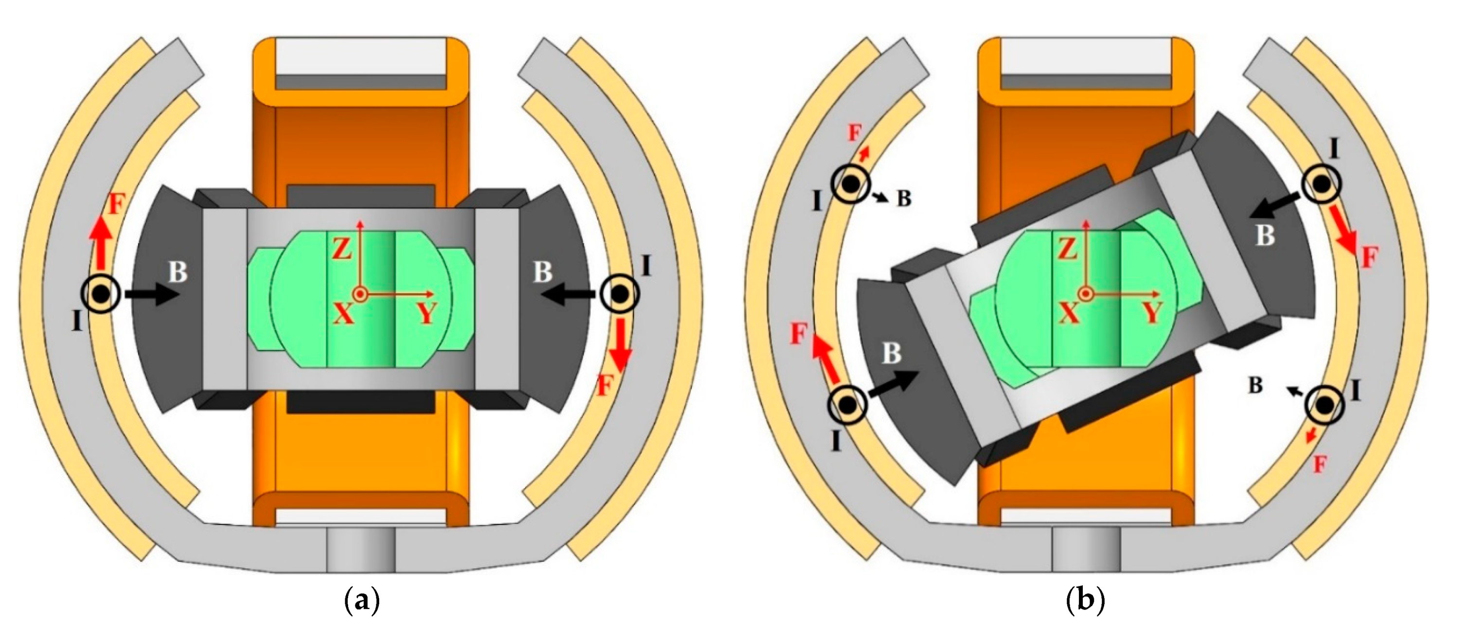
The operating principles are based on the Lorentz force of a voice coil actuator (VCA) or a voice coil motor (VCM) and the magnetic attractive force between the outer yoke A and the permanent magnet. Figure 4a,b shows the Y-Z cross-section of the original 3-DOF spherical motor when the rotor is rotating around the X-axis at 0° and 25°, respectively. It can be observed that when the rotor is rotating around the X-axis from 0° to 25° in a counter-clockwise direction, the Lorentz force from a part of the coils and the permanent magnets is very small due to the weak magnetic flux [27]. In other words, the power efficiency of the original 3-DOF spherical motor is low and could be improved. As a result, the original 3-DOF spherical motor [25] is modified in this study to accomplish a 3-DOF spherical motor for a camera module with higher torque output in the large rotation angle.

3. Design of Proposed 3-DOF Spherical Motor

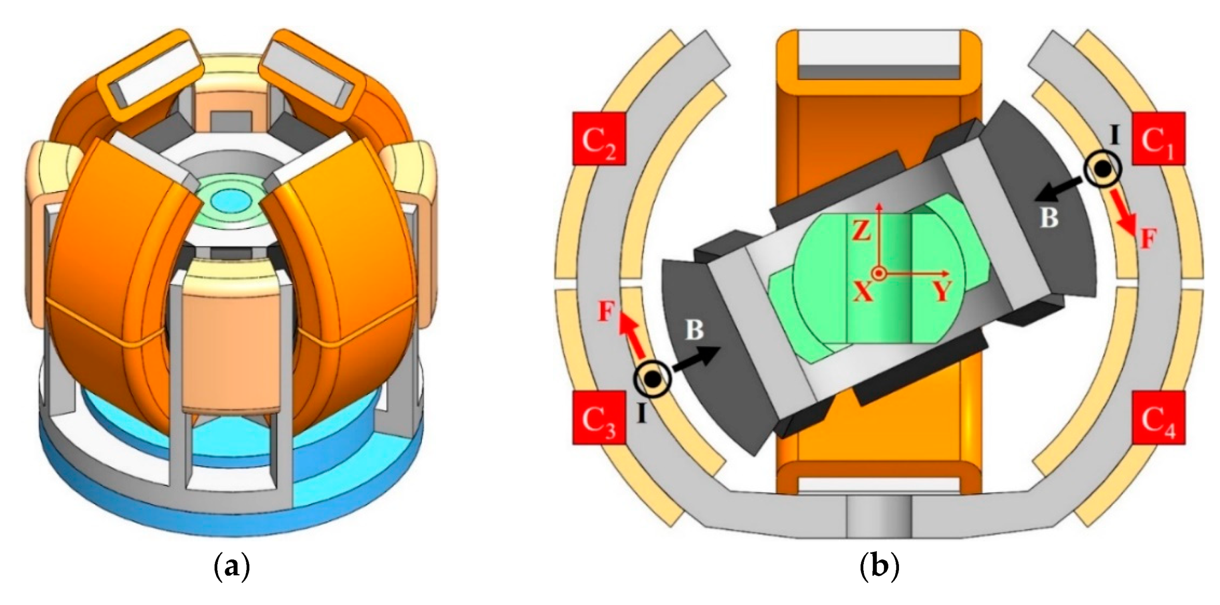
This section introduces the basic structure of the proposed 3-DOF spherical motor in this study. Its basic structure is shown in Figure 5a. When comparing Figure 1 and Figure 5a, the proposed 3-DOF spherical motor has the same structure except for 8 symmetrical coils wound around the outer yoke A. As shown in Figure 5a, 8 symmetrical coils are wound around the outer yoke A. Among the 8 coils, 4 coils are used for rotating around the X-axis, and other coils are used for rotating around the Y-axis.
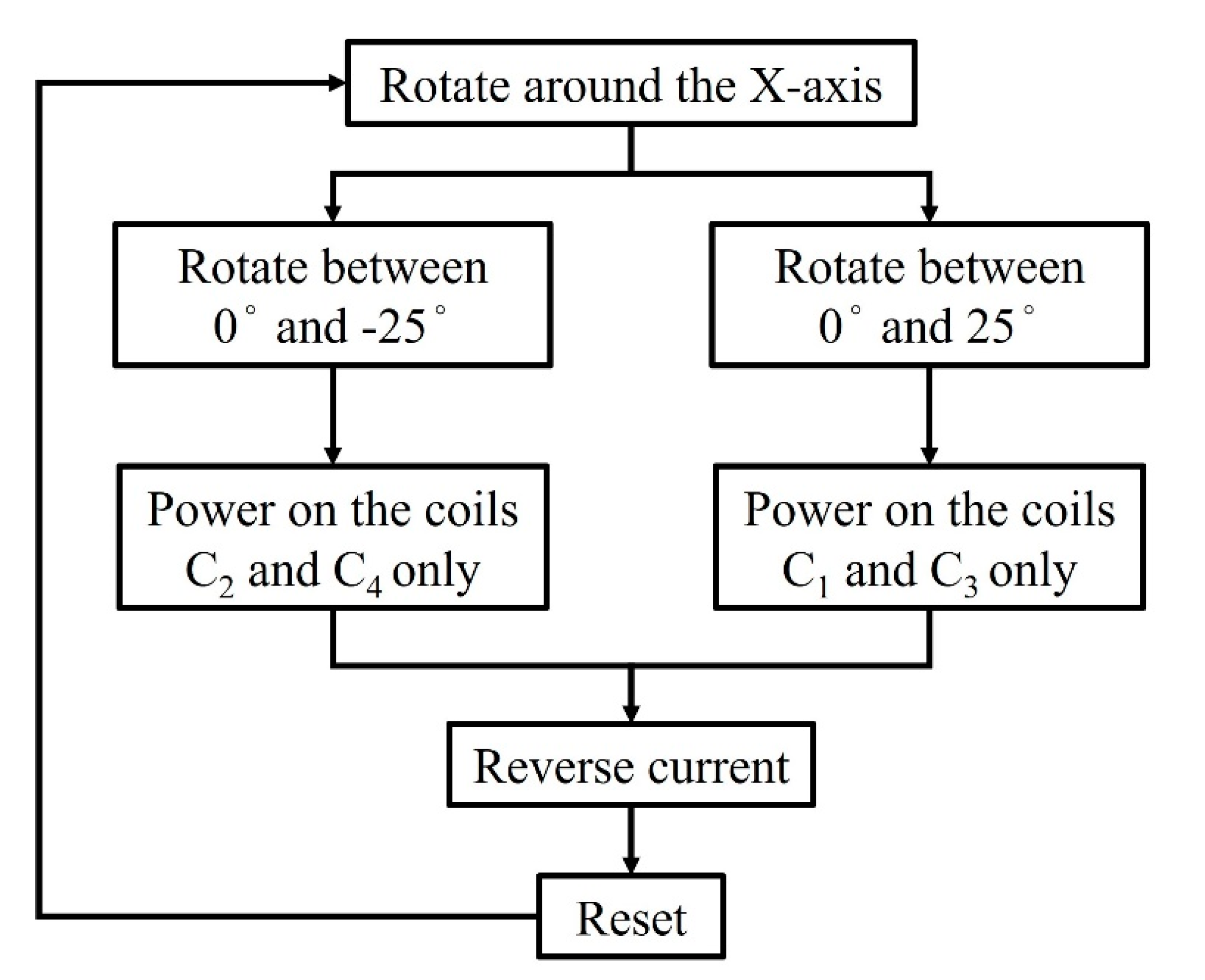
Figure 5b shows the Y-Z cross-section of the proposed 3-DOF spherical motor when the rotor is rotating around the X-axis at 25°. Here, the 4 coils are called C1, C2, C3, and C4, respectively. As shown, when the rotor is rotating around the X-axis from 0° to 25° in a counter-clockwise direction, the magnetic flux through the coils C2 and C4 is too weak, so the coils C2 and C4 are turned off in the proposed design. Due to the proposed electromagnetic structure with a particular controlling strategy, the proposed 3-DOF spherical motor has higher torque output in the large rotation angle when compared to the original 3-DOF spherical motor [25]. The flowchart designed to actuate the proposed 3-DOF spherical motor for rotating around the X-axis is illustrated in Figure 6. In this paper, we discuss the actuator rotating around the X-axis between 0° and 25°, so we only need to power on the coil C1 and C3. For another scenario, if we want to let the actuator rotate around the X-axis between 0° and −25°, we only need to power on the coil C2 and C4. In the next section, the improvement in the static torque of the proposed 3-DOF spherical motor is verified by using the 3D FEM.

4. 3D FEM Simulation

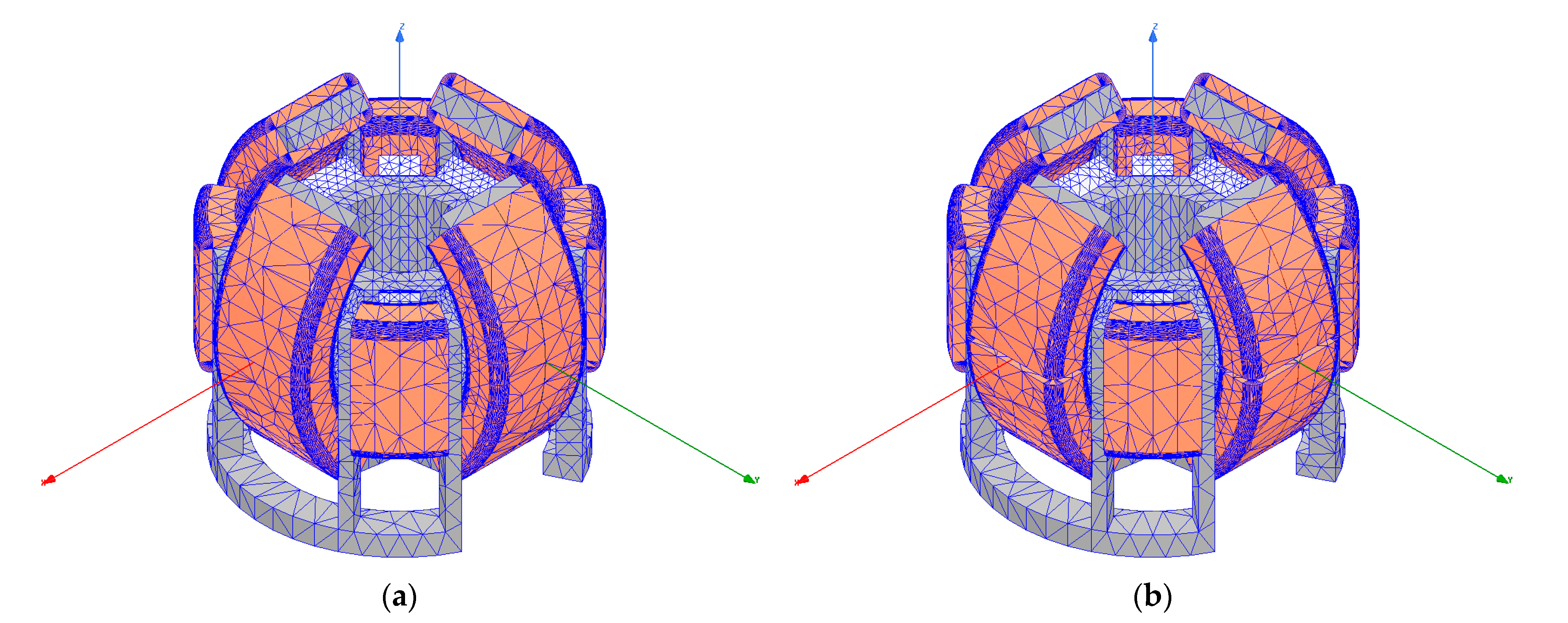
To compare the torque output of the original 3-DOF spherical motor and the proposed 3-DOF spherical motor, ANSYS, a commercial software, was utilized to demonstrate their performance. Here, the 3D FEM was used to demonstrate the results of torque output and magnetic flux density distribution because the original 3-DOF spherical motor and the proposed 3-DOF spherical motor are not full symmetry. Figure 7a,b show the 3D FEM models of the original 3-DOF spherical motor and the proposed 3-DOF spherical motor, respectively.
From Figure 1 and Figure 5, because the structure of the original 3-DOF spherical motor and the proposed 3-DOF spherical motor for rotating around the Y-axis is the same as that for rotating around the X-axis, only 3D FEM simulations for rotating around the X-axis were performed and compared. In the simulations, the materials of the yokes, the coils, and the permanent magnets are selected as steel-1008, copper, and NdFe35, respectively. In the original 3-DOF spherical motor, each coil for rotating around the X-axis, Y-axis, and Z-axis has 900, 900, and 250 turns, respectively. By calculating, the inductance and resistance of each coil for rotating around the X- and Y-axes are 7.9 × 10⁻⁷ H and 19.2 Ω, respectively; those of each coil for rotating around the Z-axis are 2.2 × 10⁻⁷ H and 6.5 Ω, respectively. In the proposed 3-DOF spherical motor, each coil for rotating around the X-axis, Y-axis, and Z-axis have 450, 450, and 250 turns, respectively. By calculating, the inductance and resistance of each coil for rotating around the X- and Y-axes are 4.0 × 10⁻⁷ H and 9.6 Ω, respectively; those of each coil for rotating around the Z-axis are 2.2 × 10⁻⁷ H and 6.5 Ω, respectively. The current 0.25 A was selected to pass each coil of the original and proposed 3-DOF spherical motor. Therefore, the current density of the original and proposed structure is 1.4 × 10⁷ A/m2. The diameter of the coils is 0.15 mm for both the original 3-DOF spherical motor and proposed 3-DOF spherical motor. It is noted that for the original 3-DOF spherical motor [25] and proposed 3-DOF spherical motor, the main driving range of both motors is around the origin, and the coils are switched at the same high speed for both motors. Here, the power consumption issue for the driving circuit is ignored.
For a fair comparison, the original 3-DOF spherical motor and the proposed 3-DOF spherical motor are assumed to have the same power consumption. For the original 3-DOF spherical motor, in the simulation case for rotating around the X-axis, the power consumption Po can be expressed as:
Po = 2 Io2Ro,
where Io and Ro are the current and the resistance of each coil, respectively, for the original 3-DOF spherical motor. For the proposed 3-DOF spherical motor, in the simulation case for rotating around the X-axis, the power consumption Pp can be expressed as:
Pp = 2 Ip2Rp,
where Ip and Rp are the current and the resistance of each coil, respectively, for the proposed 3-DOF spherical motor. It is noted that
Rp = 1/2Ro.
Let Po = Pp, from Equations (1)–(3), the following equation can be obtained:
Ip = √2Io.
In the simulations, we show two possibility cases. The first one is under the same input current of 0.25 A, and the second is under the same power consumption, which means that the input current of the original motor is 0.25 A, and that of the proposed motor is 0.25√2 A.

5. Numerical Results of 3D FEM and Discussion

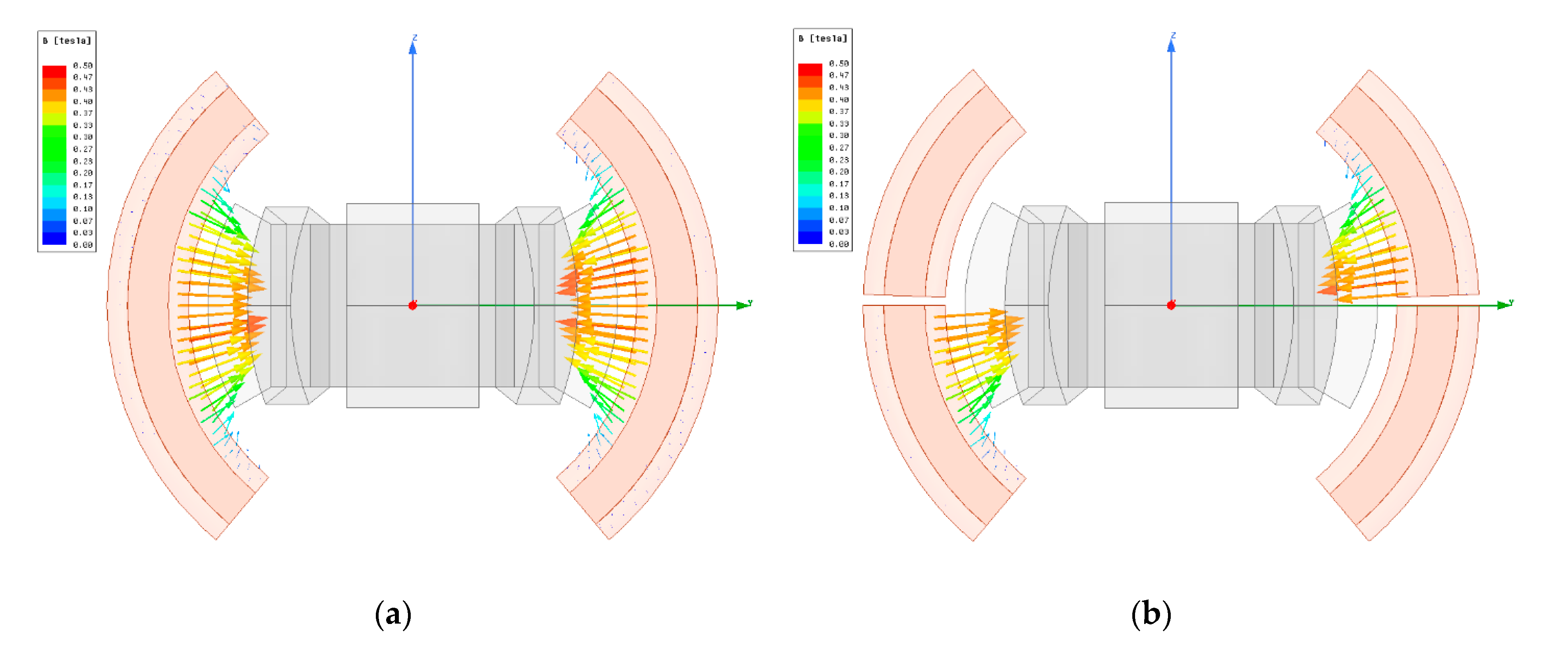
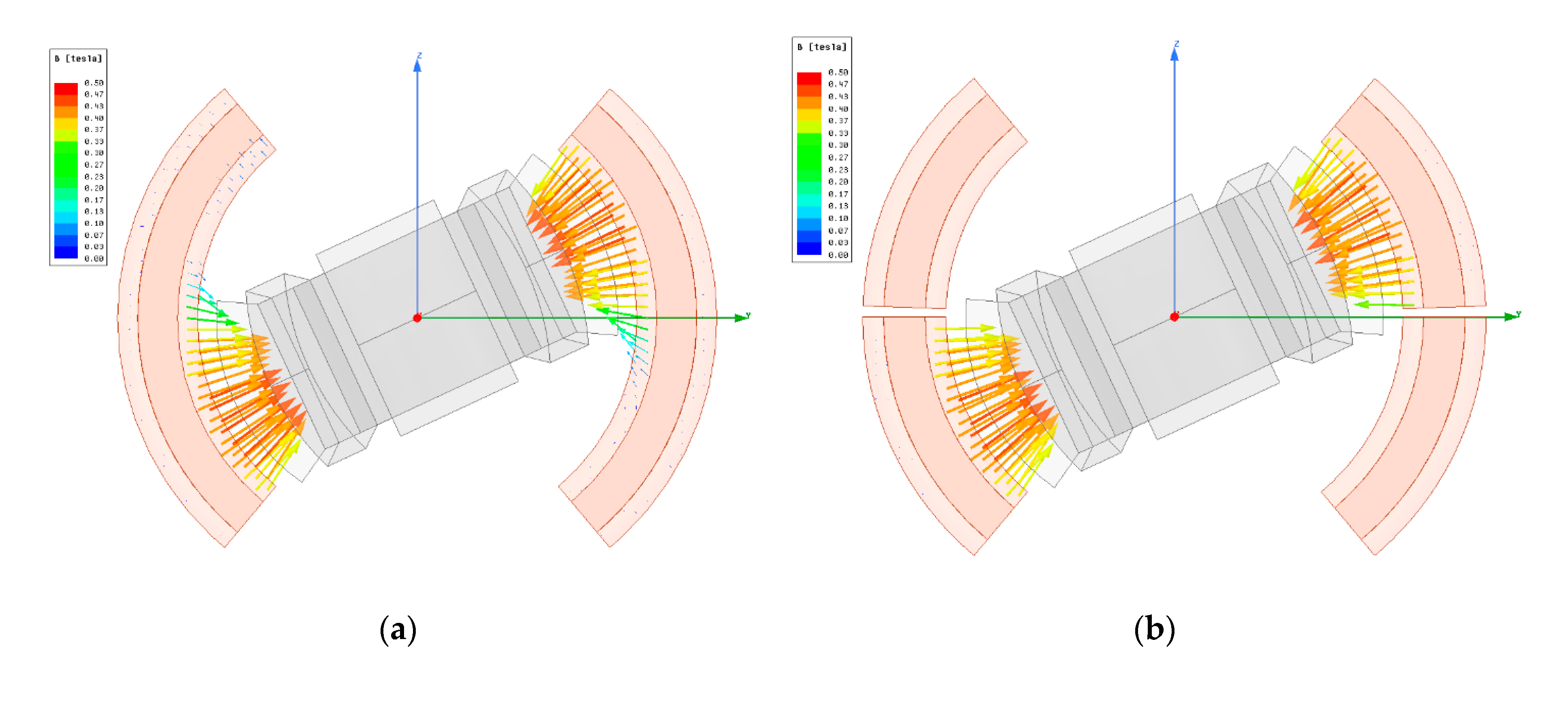
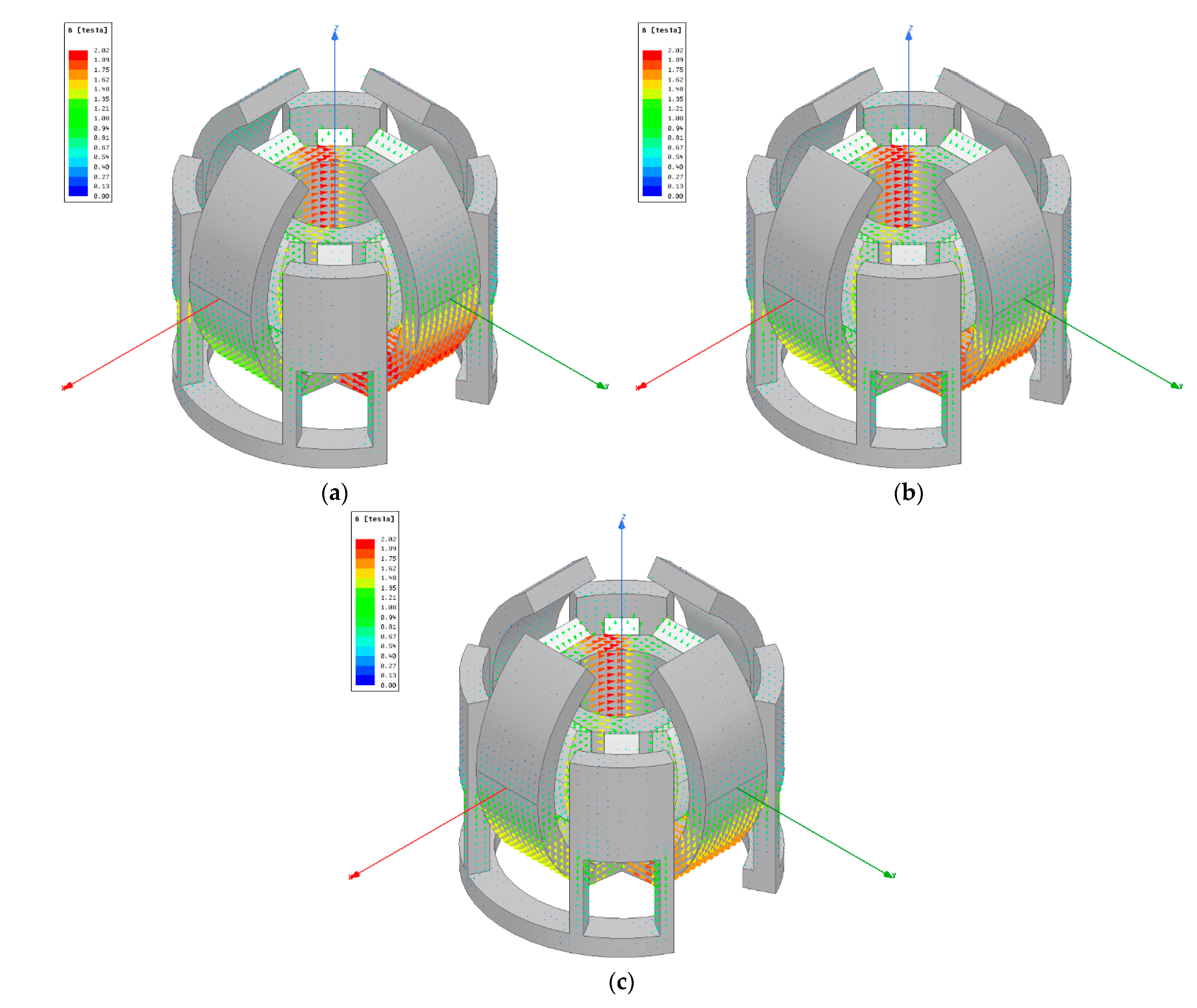
Figure 8 and Figure 9 show the magnetic flux density distribution of Y-Z cross-section when the rotor is rotating around the X-axis at 0° and 25° for the original 3-DOF spherical motor and the proposed 3-DOF spherical motor, respectively. The movies for the magnetic flux density change in Y-Z cross-section when the rotor is rotating around the X-axis from 0° to 25° are provided in Videos S1 and S2 of the Supplementary Materials, respectively. As shown, when the rotor of the original 3-DOF spherical motor is rotating around the X-axis from 0° to 25° in a counter-clockwise direction, the magnetic flux into the upper part of the coils in the left side is very weak, which agrees to the viewpoint in Section 2. Figure 8 and Figure 9 only show the magnetic flux density distribution of the coils and the magnet. Based on Ampère’s circuital law, the magnetic field generated from the energized coils must be considered. The vector diagram of the magnetic flux density distribution in the yoke and magnet is shown in Figure 10.
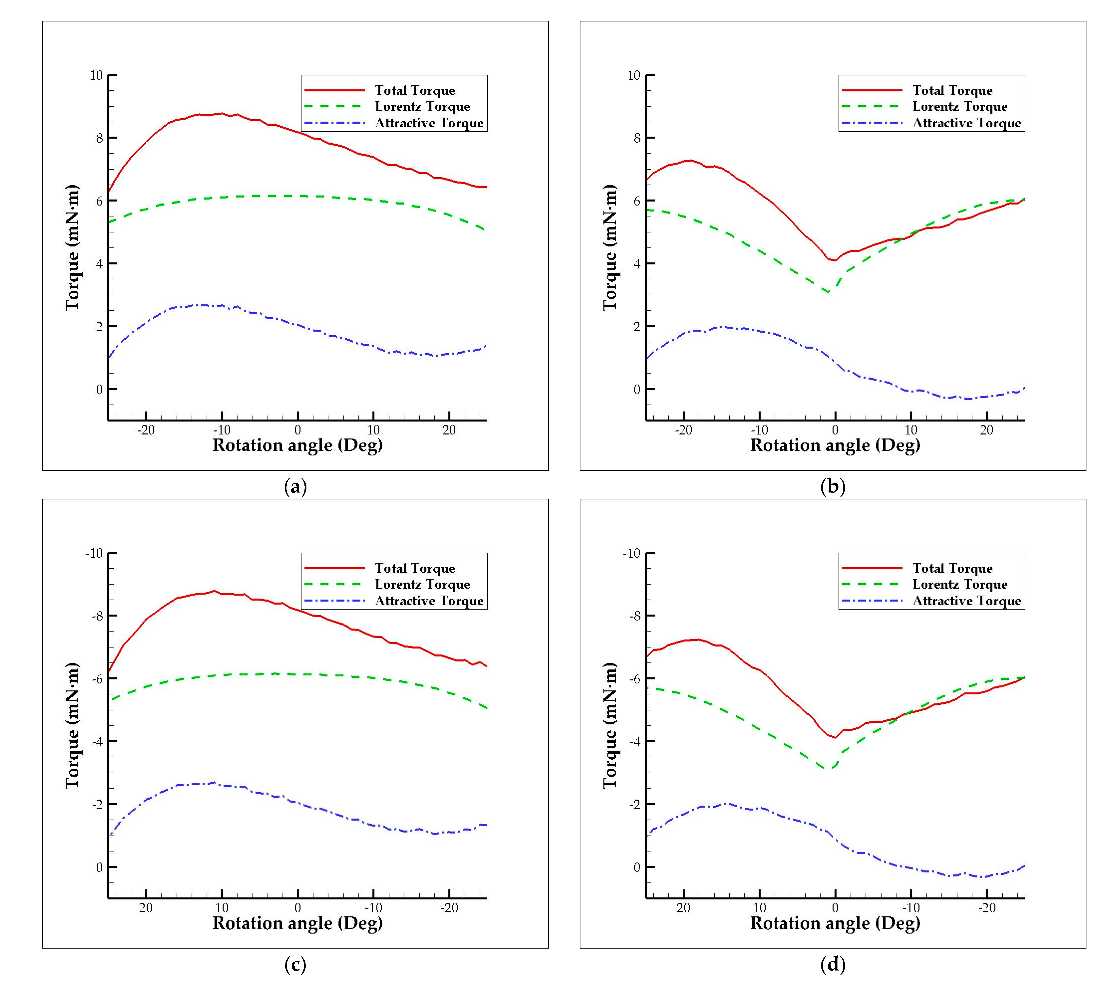
Under the same input current of 0.25 A, Figure 11 shows the numerical results with a step size of 1° obtained for the torque change with respect to the different rotation angle of the original and the proposed 3-DOF spherical motor either in a counter-clockwise direction or in a clockwise direction. When the rotor rotates in a counter-clockwise direction, the direction of the current is out of the page, such as in Figure 4. By contrast, when the rotor rotates in a clockwise direction, the direction of the current is into the page. The torque values due to Lorentz force and magnetic attractive force are listed in Table 3 and Table 4. For easier reading, the results in Table 3 and Table 4 are shown with step size of 5° only. In the original structure, as shown in Figure 8a and Figure 9a and Video S1, the torque output decreases in the large rotation angle because the effective area of the magnetic flux through the coils becomes small. In the proposed structure, as shown in Figure 8b and Figure 9b and Video S2, the torque output increases with the rotation angle because the effective area of the magnetic flux through the coils increases along with the rotation angle. In addition, because the effective area of the magnetic flux through the coils in the original structure is larger than that in the proposed structure, the torque output of the original structure is larger than that of the proposed structure around the origin. Finally, from the ratio of the torque due to Lorentz force and magnetic attractive force as shown in Table 3 and Table 4, it is clarified that the proposed motor has a specific structure that utilizes the Lorentz force more actively when compared to the original motor.
However, in Table 5, we present their comparisons in a different way. Based on the same copper loss and power, the input current of the proposed motor is √2 times as large as that of the original motor. A current of 0.25√2 A was selected to pass each coil of the proposed motor with the current density of 2 × 10⁷ A/m2. For easier reading, the results in Table 5 are also shown with step size of 5° except the magnitude of the average values in the bottom. Based on the same design parameters, the improvement percentage of the torque density is the same as that of the torque output in Table 5. Here, the outermost diameter is used to calculate the motor’s volume and the torque density. It is obvious that the greater the rotation angle, the lower the efficiency for the original 3-DOF spherical motor; in contrast, the greater the rotation angle, the higher the efficiency for the proposed 3-DOF spherical motor.
Finally, from the ANSYS dynamic simulation, the response time of the rotor moving from −25° to +25° in a counter-clockwise direction are 0.0763 s and 0.0699 s for the original and proposed 3-DOF spherical motor, respectively. There is a better performance in response time for the proposed 3-DOF spherical motor. Detailly, the calculation process of the dynamic simulation is to compute the time step to reach the next angle by angular acceleration and angular velocity, which are calculated from the torque generated from the magnetostatic analysis. Therefore, the actual parameter setting for simulation and step size of the rotation angle is 1° in this paper. The torque and time step are the output, in which the minimum time step is 0.0007 s by calculating.
In addition, the proposed 3-DOF spherical motor has a greater torque output in the large rotation angle and has an average improvement percentage of 5.22% when compared to the original 3-DOF spherical motor. In other words, the proposed 3-DOF spherical motor has a nice improvement in the large rotation angle by using the novel electromagnetic structure with a particular controlling strategy. In this paper, we mainly focus on the improvement of the torque output for the rotation around the X- and Y-axes. Avoiding the text repeatability, we ignored the detail information. Note that for a more comprehensive description of the original system, the reader is referred to [25,26]. The main contribution of this study is to propose this design and verify its performance by using a 3D FEM. A prototype of the proposed 3-DOF spherical motor will be built to demonstrate its dynamic performance in a future work, and the driving circuit will also be designed by referring to the previous study [25,26].

6. Conclusions

This study has proposed a modified 3-DOF spherical motor with an improved electromagnetic structure and a particular controlling strategy. The proposed motor has a compact diameter of 28 mm. Moreover, it has a movable angle of ±25° along the X- and Y-axes and that of ±5° along the Z-axis. In the structural design, eight symmetrical coils with specific coil combination are used instead of conventional four symmetrical coils. The performance of the proposed 3-DOF spherical motor has been evaluated by means of a 3D FEM. The numerical results have shown that the proposed 3-DOF spherical motor has higher torque output in the large rotation angle (average improvement percentage of 5.22%) when compared to the original 3-DOF spherical motor [25]. As a result, the proposed 3-DOF spherical motor provides a promising solution for a wide application of the humanoid and autonomous systems, such as joints and eyeballs of the humanoid, unmanned aerial vehicles, autonomous cars, walking robots, and other fields.

7. Patents

The proposed electromagnetic structure with a particular controlling strategy reported in this study is applying for USA and Taiwan patents.

Supplementary Materials

The following are available online at https://www.mdpi.com/article/10.3390/app11156872/s1, Video S1: Magnetic flux density change in Y-Z cross-section when the rotor is rotating around the X-axis for original 3-DOF spherical motor. Video S2: Magnetic flux density change in Y-Z cross-section when the rotor is rotating around the X-axis for proposed 3-DOF spherical motor.

Author Contributions

Conceptualization, C.-S.L. and Y.-H.L.; methodology, C.-S.L. and Y.-H.L.; validation, Y.-H.L. and C.-N.Y.; investigation, C.-S.L. and Y.-H.L.; writing—original draft preparation, C.-S.L.; writing—review and editing, C.-S.L.; supervision, C.-S.L.; project administration, C.-S.L.; funding acquisition, C.-S.L. All authors have read and agreed to the published version of the manuscript.

Funding

This research was funded by the Ministry of Science and Technology of Taiwan, grant numbers MOST 109-2218-E-002-006, 108-2218-E-002-071, 106-2628-E-194-001-MY3, and 105-2221-E-194-013-MY5.

Acknowledgments

Ansys Inc. is thanked for providing ANSYS academic partner program.

Conflicts of Interest

The authors declare no conflict of interest.

References

  1. Xu, J.; Wang, Q.; Li, G.; Zhou, R.; Wen, Y.; Ju, L.; Zhou, S. Sensorless Posture Detection of Reluctance Spherical Motor Based on Mutual Inductance Voltage. Appl. Sci. 2021, 11, 3515. [Google Scholar] [CrossRef]
  2. Cho, S.; Lim, J.; Oh, Y.J.; Jeong, G.; Kang, D.; Lee, J. A Study on Output Characteristics of the Spherical Multi-DOF Motor According to the Number of Phases and Pole Pitch Angles. IEEE Trans. Magn. 2018, 54, 8205005. [Google Scholar] [CrossRef]
  3. Hong, M.B.; Jo, Y.-H. Design of a novel 4-DOF wrist-type surgical instrument with enhanced rigidity and dexterity. IEEE/ASME Trans. Mechatron. 2014, 19, 500–511. [Google Scholar] [CrossRef]
  4. Palpacelli, M.C.; Carbonari, L.; Palmieri, G.; Callegari, M. Analysis and design of a reconfigurable 3-DoF parallel manipulator for multimodal tasks. IEEE/ASME Trans. Mechatron. 2015, 20, 1975–1985. [Google Scholar] [CrossRef]
  5. Jūrėnas, V.; Kazokaitis, G.; Mažeika, D. Design of Unimorph Type 3DOF Ultrasonic Motor. Appl. Sci. 2020, 10, 5605. [Google Scholar] [CrossRef]
  6. Jūrėnas, V.; Kazokaitis, G.; Mažeika, D. 3DOF Ultrasonic Motor with Two Piezoelectric Rings. Sensors 2020, 20, 834. [Google Scholar] [CrossRef] [Green Version]
  7. Dehez, B.; Galary, G.; Grenier, D.; Raucent, B. Development of a spherical induction motor with two degrees of freedom. IEEE Trans. Magn. 2006, 42, 2077–2089. [Google Scholar] [CrossRef]
  8. Song, M.G.; Hur, Y.J.; Park, N.C.; Park, K.S.; Park, Y.P.; Lim, S.C.; Park, J.H. Design of a voice-coil actuator for optical image stabilization based on genetic algorithm. IEEE Trans. Magn. 2009, 45, 4558–4561. [Google Scholar] [CrossRef]
  9. Song, M.G.; Baek, H.W.; Park, N.C.; Park, K.S.; Yoon, T.; Park, Y.P.; Lim, S.C. Development of small sized actuator with compliant mechanism for optical image stabilization. IEEE Trans. Magn. 2010, 46, 2369–2372. [Google Scholar] [CrossRef]
  10. Sakaidani, Y.; Hirata, K.; Maeda, S.; Niguchi, N. Feedback control of the 2-DOF actuator specialized for 2-axes rotation. IEEE Trans. Magn. 2013, 49, 2245–2248. [Google Scholar] [CrossRef]
  11. Hsieh, C.L.; Wang, H.Y.; Chang, Y.H.; Liu, C.S. Design of VCM actuator with the chamfered edge magnet for cellphone. Microsyst. Technol. 2017, 23, 5293–5302. [Google Scholar] [CrossRef]
  12. Hsieh, C.L.; Chang, Y.H.; Chen, Y.T.; Liu, C.S. Design of VCM actuator with L-shape coil for smartphone cameras. Microsyst. Technol. 2018, 24, 1033–1040. [Google Scholar] [CrossRef]
  13. Kwon, T.H.; Ro, J.S. Analysis and Optimal Design of a Novel Actuator System for a Camera Module. IEEE Access 2020, 9, 3441–3450. [Google Scholar] [CrossRef]
  14. Li, Z.; Lun, Q.; Xing, D.; Gao, P. Analysis and implementation of a 3-DOF deflection-type PM motor. IEEE Trans. Magn. 2015, 51, 8207304. [Google Scholar] [CrossRef]
  15. Chang, Y.H.; Lu, C.J.; Liu, C.S.; Liu, D.S.; Chen, S.H.; Liao, T.W.; Peng, W.Y.; Lin, C.H. Design of miniaturized optical image stabilization and autofocusing camera module for cellphones. Sens. Mater. 2017, 29, 989–995. [Google Scholar]
  16. Heya, A.; Hirata, K.; Matsushita, T.; Kono, Y. Design and Analysis of a Three-Degree-of-Freedom Linear Oscillatory Actuator. IEEE Trans. Magn. 2020, 56, 6701404. [Google Scholar] [CrossRef]
  17. Chang, Y.H.; Hao, G.; Liu, C.S. Design and characterisation of a compact 4-degree-of-freedom fast steering mirror system based on double Porro prisms for laser beam stabilization. Sens. Actuators A Phys. 2021, 322, 112639. [Google Scholar] [CrossRef]
  18. Hsieh, C.L.; Liu, C.S.; Cheng, C.C. Design of a 5 degree of freedom–voice coil motor actuator for smartphone camera modules. Sens. Actuators A Phys. 2020, 309, 112014. [Google Scholar] [CrossRef]
  19. Son, H.; Lee, K.M. Open-loop controller Design and Dynamic Characteristics of A Spherical Wheel motor. IEEE Trans. Ind. Electron. 2010, 57, 3475–3482. [Google Scholar] [CrossRef]
  20. Wang, J.; Jewell, G.W.; Howe, D. A Novel Spherical Actuator: Design and Control. IEEE Trans. Magn. 1997, 33, 4209–4211. [Google Scholar] [CrossRef]
  21. Wang, J.; Jewell, G.W.; Howe, D. Analysis, Design and Control of A Novel Spherical Permanent-magnet Actuator. IEEE Proc. Electr. Power Appl. 1998, 145, 61–71. [Google Scholar] [CrossRef]
  22. Fusayasu, H.; Masuyama, Y.; Hirata, K.; Niguchi, N.; Takahara, K. Analysis Accuracy in Positioning Calculation for Three-Degree-of-Freedom Spherical Actuator. IEEE Trans. Magn. 2021, 57, 8204104. [Google Scholar] [CrossRef]
  23. Yang, L.; Chen, I.-M.; Yang, G.; Lee, K.-M. Analytical and experimental investigation on the magnetic field and torque of a permanent magnet spherical actuator. IEEE Trans. Mechatron. 2006, 11, 409–419. [Google Scholar] [CrossRef]
  24. Heya, A.; Hirata, K.; Ezaki, S.; Ota, T. Dynamic Analysis of a new three-degree-of-freedom actuator for image stabilization. IEEE Trans. Magn. 2017, 53, 2706942. [Google Scholar] [CrossRef]
  25. Heya, A.; Hirata, K.; Niguchi, N. Dynamic modeling and control of three-degree-of-freedom electromagnetic actuator for image stabilization. IEEE Trans. Magn. 2018, 54, 8207905. [Google Scholar] [CrossRef]
  26. Heya, A.; Hirata, K. Experimental verification of three-degree-of-freedom electromagnetic actuator for image stabilization. Sensors 2020, 20, 2485. [Google Scholar] [CrossRef]
  27. Lin, Y.H.; Liu, C.S.; Yeh, C.N. Design and Simulation of Novel 3-DOF Spherical Voice Coil Motor. Actuators 2021, 10, 155. [Google Scholar] [CrossRef]
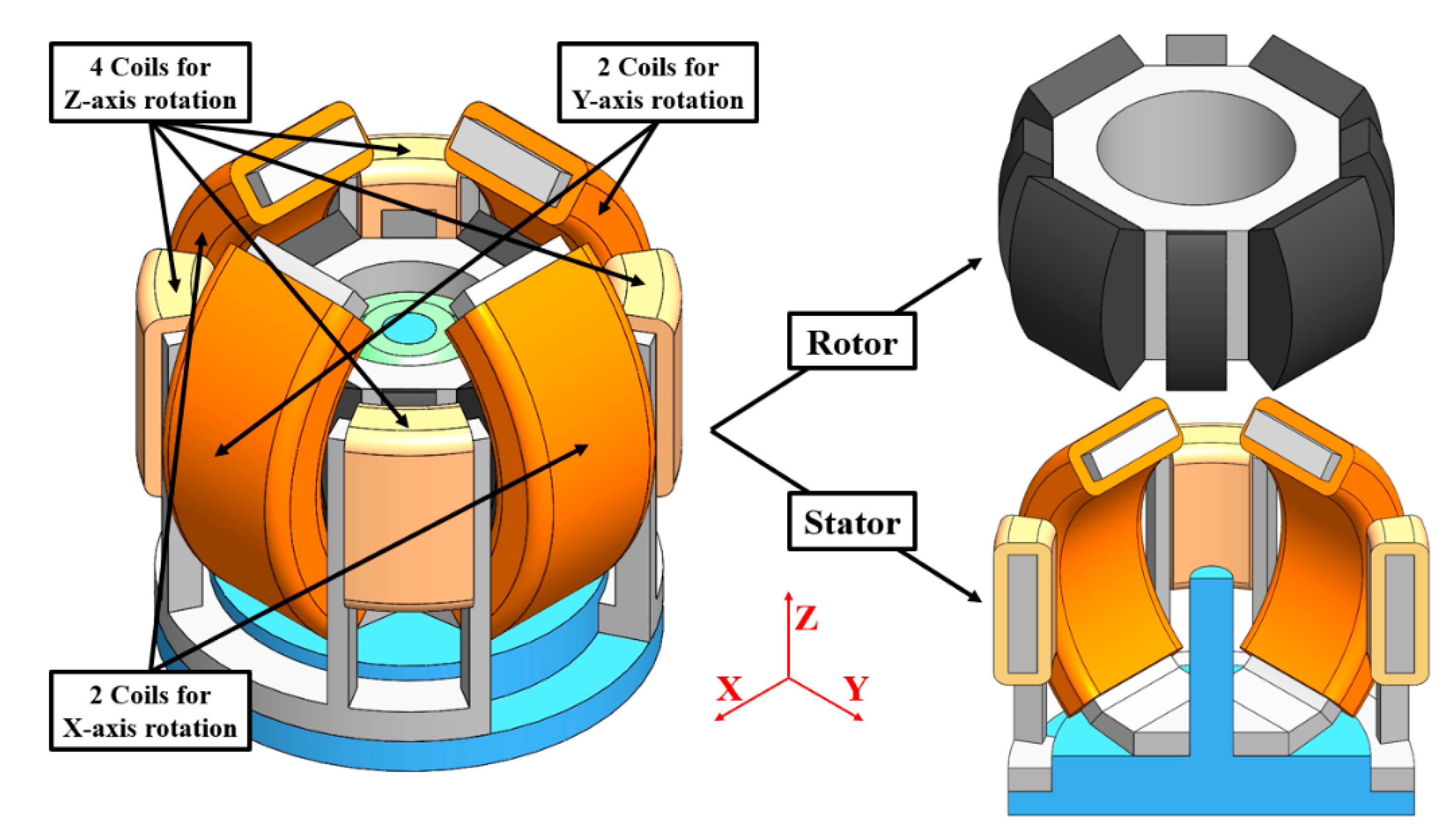
Figure 1. Basic structure of original 3-DOF spherical motor.
Applsci 11 06872 g001
Figure 2. (a) Detailed components and (b) magnetization of permanent magnets in original 3-DOF spherical motor.
Applsci 11 06872 g002
Figure 3. Design parameters of original 3-DOF spherical motor: (a) Y-Z and (b) X-Y cross-section.
Applsci 11 06872 g003
Figure 4. Y-Z cross-section of original 3-DOF spherical motor when the rotor is rotating around the X-axis at (a) 0° and (b) 25°, respectively.
Applsci 11 06872 g004
Figure 5. (a) Basic structure of proposed 3-DOF spherical motor; (b) Y-Z cross-section of proposed 3-DOF spherical motor when the rotor is rotating around the X-axis at 25°.
Applsci 11 06872 g005
Figure 6. Flowchart to actuate proposed 3-DOF spherical motor for rotating around the X-axis.
Applsci 11 06872 g006
Figure 7. 3D FEM models of (a) original and (b) proposed 3-DOF spherical motor, respectively.
Applsci 11 06872 g007
Figure 8. Magnetic flux density distribution of Y-Z cross-section when the rotor is rotating around the X-axis at 0° for (a) original and (b) proposed 3-DOF spherical motor, respectively.
Applsci 11 06872 g008
Figure 9. Magnetic flux density distribution of Y-Z cross-section when the rotor is rotating around the X-axis at 25° for (a) original and (b) proposed 3-DOF spherical motor, respectively.
Applsci 11 06872 g009
Figure 10. The vector diagram of the magnetic flux density distribution in the yoke and magnet when the coils of (a) original and (b) proposed 3-DOF spherical motor are powered on and (c) those are not powered on, respectively.
Applsci 11 06872 g010
Figure 11. Numerical results obtained for the torque output with respect to different rotation angle of, respectively, (a) original and (b) proposed 3-DOF spherical motor rotating from −25° to +25° in a counter-clockwise direction and (c) original and (d) proposed 3-DOF spherical motor rotating from +25° to −25° in a clockwise direction with reverse axis direction.
Applsci 11 06872 g011
Table 1. Performance comparison list of several kinds of 3-DOF motors.
TypeVoice Coil
Motor Type
Stepping
Motor Type
Induction
Motor Type
Synchronous
Motor Type
Reluctance
Motor Type
ControlSimpleComplexComplexComplexMedium
StructureSimpleComplexComplexComplexSimple
ResponseHighMediumMediumMediumLow
Positioning
accuracy
HighLowLowHighLow
Force/TorqueLowMediumHighMediumHigh
Cogging effectNoYesNoYesNo
Table 2. Values of design parameters of original 3-DOF spherical motor.
SymbolCorresponding ParameterValue
DO1, DO2Outermost diameter28.0 (mm)
tO1, tO2Outer yoke thickness2.0 (mm)
tg1Air gap length2.0 (mm)
tg22.1 (mm)
tm1Permanent magnet thickness3.1 (mm)
tm22.7 (mm)
tiInner yoke thickness8.0 (mm)
θm1, θm2Permanent magnet angle60.0 (deg)
θO1, θO2Outer yoke angle70.0 (deg)
wO1Outer yoke width7.5 (mm)
wO210.0 (mm)
wm1Permanent magnet width6.5 (mm)
wm23.0 (mm)
wi1Inner yoke width13.9 (mm)
wi214.4 (mm)
Table 3. Torque output of original 3-DOF spherical motor.
Rotation Angle
(Deg)
Total Torque Output
(mN·m)
Lorentz Torque Output
(mN·m)
Attractive Torque Output
(mN·m)
Ratio of Lorentz and Attractive Torque Output
Rotate from −25° to +25° in a counter-clockwise direction
−256.295.310.995.38
−207.865.732.132.69
−158.605.992.612.30
−108.786.102.672.28
−58.566.152.412.56
08.186.142.043.01
57.786.091.693.60
107.386.021.364.45
157.025.841.184.94
206.655.541.124.95
256.435.021.413.56
Rotate from +25° to −25° in a clockwise direction
25−6.23−5.29−0.945.65
20−7.89−5.74−2.152.67
15−8.60−6.00−2.602.30
10−8.68−6.11−2.572.38
5−8.50−6.15−2.352.62
0−8.17−6.13−2.043.01
−5−7.79−6.10−1.683.63
−10−7.33−6.01−1.324.56
−15−7.00−5.84−1.165.04
−20−6.65−5.54−1.114.98
−25−6.38−5.04−1.343.76
Table 4. Torque output of proposed 3-DOF spherical motor.
Rotation Angle
(Deg)
Total Torque Output
(mN·m)
Lorentz Torque Output
(mN·m)
Attractive Torque Output
(mN·m)
Ratio of Lorentz and Attractive Torque Output
Rotate from −25° to +25° in a counter-clockwise direction
−256.645.720.936.18
−207.265.491.773.11
−157.035.032.002.52
−106.224.391.842.38
−55.133.691.452.55
04.093.230.863.77
54.584.270.3113.66
104.874.95−0.08−61.36
155.245.52−0.29−19.33
205.665.90−0.24−24.94
256.076.020.05123.17
Rotate from +25° to −25° in a clockwise direction
25−6.67−5.71−0.965.94
20−7.20−5.51−1.693.25
15−7.04−5.02−2.022.49
10−6.27−4.38−1.892.32
5−5.16−3.68−1.482.49
0−4.11−3.23−0.873.71
−5−4.62−4.28−0.3512.39
−10−4.92−4.950.03−162.85
−15−5.25−5.530.28−20.01
−20−5.60−5.900.30−19.54
−25−6.04−6.01−0.04170.21
Table 5. Comparison of the torque output and torque density of original and proposed 3-DOF spherical motor.
Rotation
Angle
(Deg)
Total Torque
Output of
Original Motor
(mN·m)
Total Torque
Output of
Proposed Motor
(mN·m)
Total Torque
Density of
Original Motor
(kN·m/m3)
Total Torque
Density of
Proposed Motor
(kN·m/m3)
Improvement
Percentage
(%)
Rotate from −25° to +25° in a counter-clockwise direction
−256.299.010.550.7843.13
−207.869.720.680.8523.56
−158.609.380.750.828.99
−108.788.340.760.73−4.95
−58.566.980.740.61−18.49
08.185.760.710.50−29.64
57.786.690.680.58−14.06
107.387.280.640.63−1.34
157.027.880.610.6912.22
206.658.440.580.7326.87
256.438.860.560.7737.68
Rotate from +25° to −25° in a clockwise direction
25−6.23−9.08−0.54−0.7945.88
20−7.89−9.64−0.69−0.8422.19
15−8.60−9.38−0.75−0.829.14
10−8.68−8.40−0.76−0.73−3.30
5−8.50−6.99−0.74−0.61−17.76
0−8.17−5.78−0.71−0.50−29.30
−5−7.79−6.74−0.68−0.59−13.50
−10−7.33−7.32−0.64−0.64−0.17
−15−7.00−7.91−0.61−0.6912.95
−20−6.65−8.38−0.58−0.7325.97
−25−6.38−8.81−0.55−0.7738.24
Average
(Magnitude)
7.697.980.670.695.22
Publisher’s Note: MDPI stays neutral with regard to jurisdictional claims in published maps and institutional affiliations.