Abstract
This study focused on characteristic cases of recently tested real-scale RC framed wall infilled structures with innovative seismic protection through polyurethane joints (PUFJ) or polyurethane-impregnated fiber grids (FRPU). The frames revealed a highly ductile response while preventing infill collapse. Herein, suitable 3D pseudo-dynamic FE models were developed in order to reproduce the experimental results. The advanced Explicit Dynamics framework may help reveal the unique features of the considered interventions. Externally applied double-sided FRPU jackets on OrthoBlock infills may maintain an adequate bond with the surrounding RC frame as well as with the brick infill substrate at up to a 3.6% drift. In a weak four-column RC structure, the OrthoBlock infills with PUFJ seismic joints may increase the initial stiffness remarkably, increase the base shear by three times (compared with the bare structure) and maintain a high horizontal drift of 3.7%. After this phase, the structure may receive FRPU retrofitting, reveal the redistribution of stress over broad infill regions, including predamaged parts, and still develop a higher initial stiffness and base shear (compared with the bare RC). The realization of a desirable ductile behavior of infilled frames through PUFJ of only 20 mm thickness, as well as through FRPU jacketing, may remarkably broaden the alternatives in seismic protection against the collapse of structures.
1. Introduction
The behavior of infilled reinforced concrete (RC) frames under in-plane and out-of-plane loading is an open issue as there is a variability of existing RC frames designed and constructed according to different design codes over the years, with or without modern seismic-resistant provisions or suitable reinforcement detailing. Further, the infills may include solid or hollow clay bricks (usually with a horizontal direction of the holes of the bricks), concrete solid or hollow blocks and several other types of infill wall units. Therefore, there is a high variation in the modulus of elasticity, strength and modes of failure of the infills when interacting with the RC frames. In some cases, the effects of the infills on the RC frames may be detrimental and lead to building collapses during severe earthquakes. On the other hand, collapsed infills alone may lead to human injuries or loss. Numerous experimental campaigns have addressed the variable behavior of infilled RC frames. The high scatter in the prediction of several critical parameters—especially the ones related to displacement ductility—reveals the complexity and uncertainty involved (see the studies by [1,2,3,4,5,6,7], among others). Furthermore, the out-of-plane response of the infills is equally crucial to predict (see, e.g., [4,8,9,10], among others). The abovementioned studies suggest that, in most cases, common clay brick infills reveal an accumulation of severe damage for the lateral drift of the infilled RC frame that ranges between 0.5 and 1.5%. Hence, they lead to reduced displacement ductility levels with respect to the case of a bare RC frame, despite the fact they increase the elastic stiffness and maximum base shear capacity of the infilled frame.
Several investigations at the building level, following rigorous assessment approaches, suggest that, in most cases, brick wall infills may enhance the performance of RC frames at low-intensity earthquake excitations (increased base shear capacity). Further, at higher intensities, shear-related failures of columns or out-of-plane collapse of damaged infills (especially if they have openings) may lead to premature exhaustion of buildings’ structural capacity (i.e., at lower drifts) with respect to the bare structure at different serviceability or ultimate limit states (see, e.g., dynamic experiments in [11] or analytical investigations in [12,13,14], among others). Wall infills are very crucial to take into account, especially in the damage assessment at serviceability limit states [14]. In any case, an increased uncertainty in building behavior should be considered as the dynamic excitation intensity is increased and/or multiple structural deficiencies are identified.
Innovative repair and strengthening solutions for RC frames with infill walls involved externally applied sprayable ductile fiber-reinforced cementitious composites [15], or fiber-reinforced polymer sheets [3,16,17], among others. Koutas et al. [18] tested RC frames infilled with brick walls, strengthened with textile-reinforced mortar. The RC frames were of old-type detailing (with inherent deficiencies). In most of the cases of such RC frames subjected to a constant vertical load and cyclic horizontal loading, the infill walls revealed limited ductility before their retrofitting. Even after their strengthening, the structural behavior and failure mechanism were similar to the as-built infilled frames. However, the retrofitted infilled RC frames exhibited a significant increase in the shear resistance and dissipated energy [19,20]. Again, usually, the accumulation of severe damage occurs for a lateral drift range between 0.5 and 1.5%. Such values for the infill performance limit the potential of the retrofitted RC frames [18]. This early damage accumulation may pose a threat, in some cases, to the targeted ductile behavior of strengthened RC frames with infill walls. For example, detrimental effects may be introduced by the highly uncertain and undesirable infill wall–RC frame interaction. Such effects may include premature shear-related failure of the columns in contact with the infills, or partial collapse of the infills, among others, or trigger an undesirable soft-story mechanism [21] and even whole-building collapse (if seismically induced overloads or out-of-plane infill collapses occur).
In general, the deterioration of the bond between commonly used cement-based materials at the boundary between the RC frame and the infill, as well as the severe damage accumulation within the fragile brick infills (subjected, mainly in plane, to variably imposed diagonal compressive deformation and suffering diagonal cracks or corner crushes), led to the development of different seismic protection solutions. Marinkovic and Butenweg [22,23] proposed a system to protect the infilled frame against in-plane and out-of-plane loads. Specially designed, three-sided elastomer joints at the infill–RC boundary interface were placed with a total thickness of 62.5 mm (25 mm plus 37.5 mm). A bottom elastomer was used as well. The composite frame sustained in-plane and out-of-plane loading, reaching a 3% ultimate drift for in-plane loading. Morandi et al. [6] proposed sliding joints inserted in the masonry at different levels with 30 mm thickness (3 × 30 = 90 mm) and deformable joints at the wall–frame interface (25 mm thickness). Similarly, the seismic protection was remarkable up to a 3% frame drift.
Real-scale shake table experiments are of great significance for the validation of novel seismic protection systems. INMASPOL (“INfills and MASonry structures protected by deformable POLyurethanes in seismic areas”—INMASPOL SERA Horizon 2020 project) involved a real-scale RC frame building subjected to multiple ground excitations on a shake table. The excitation was suitable for the validation of the out-of-plane performance of the OrthoBlock brick wall infills of the structure, protected by innovative seismic joints, as well as for their in-plane response. The joints were made of highly deformable polyurethane (polyurethane flexible joints, PUFJ) of 20 mm thickness. The structure was driven to a high lateral drift of up to 3.7% without base shear degradation and no brick infill collapse. Then, the brick infills were retrofitted with an innovative glass grid, impregnated with high-deformability polyurethane (fiber-reinforced polyurethane, FRPU) and retested (for the experimental validation, see [20,24]). The techniques of seismic joints and externally bonded fiber grid jackets have already been validated separately in real-scale RC frames subjected to pseudo-static cycles of horizontal top displacements [25]. Different frames with boundary polymer seismic joints on three or four sides were tested with a 20 mm thickness. Further, an infilled frame without seismic joints was retrofitted with a fiber grid jacket impregnated with highly deformable polyurethane. In all cases of the tested frames, the ductility of the composite frames was remarkable, and the corresponding drift ranged from 3.5% to 4.4%. However, during experimental campaigns involving large-scale frames, only a few parameters can be investigated due to the high demand of resources and time. Three-dimensional (3D) finite element (FE) modeling and analyses may help address the effects of critical design parameters (see [26,27,28,29,30,31,32,33,34], among others).
This paper developed suitable 3D pseudo-dynamic FE models for a real-scale brick infilled frame receiving external fiber grid retrofitting. Further, this study developed suitable 3D FE models of the real-scale RC INMASPOL frame building with innovative polymer seismic joints at the boundary of the infills. The analyses cover the first phase of successive shake table tests as well as the second phase of shake table tests, after retrofitting of the damaged structure with externally bonded fiber grids. The structure sustained a series of scaled modified real earthquake recordings of increasing maximum ground acceleration during tests, in accordance with the dynamic pushover approach. The analyses presented herein concern the inelastic pseudo-dynamic pushover response of the structure through imposed top displacements. Bare structure analysis is also included for comparative investigations. The 3D FE analyses’ results compare well with the experimental ones and may provide a unique insight on the variable interaction of the brick infill–RC frame with seismic polymer joints and retrofitting through FRP jacketing. The results help to elucidate the unique features of the interventions that enable the investigated RC framed structures to reveal high top displacement ductility. Suitable combined retrofits are also examined.
2. Brief Presentation of Existing Experimental Results
2.1. Seismic Protection of Infilled RC Frames with FRP Jackets
Herein, the experimental results of the real-scale RC frame A2R from the study by [25,35] were considered for the analytical elaborations. The RC frame had plane dimensions of a 270 cm-long beam with extensions of 30 cm on both sides and a height of 245 cm (245 cm to the level of the diaphragm). The columns had cross-section dimensions of 25 × 25 cm, 8Φ16 longitudinal continuous rebars (without lap splices) and Φ10/100 mm closed stirrups (one peripheral and one rhombic per 100 mm). The columns had two top extensions of 30 cm, as well as a common foundation beam with dimensions of 30 × 40 × 355 cm. The top beam had cross-section dimensions of 25 × 25 cm and was reinforced with 8Φ14 longitudinal rebars and Φ10/100 mm closed stirrups (peripheral). The dimensions of the RC frame and the detailing of the internal steel reinforcement are presented in Figure 1a and in Table 1. Specimen A2R included an infill wall with special thermal insulating hollow clay units, KEBE OrthoBlocks K100 (KEBE, Greece), with dimensions of 100/240/250 mm and a weight of about 100 kg/m2 (infill wall with vertical holes in the bricks), built with mortar. The mortar for the building of the walls (with nominal strength class M10) formed 3 mm-thick layers at the head or bed joints as well as at the infill–RC frame interface (no seismic joint). The infill was retrofitted with an external glass grid (of type SikaWrap 350 G Grid, with a real weight of 360 g/m2) impregnated with highly deformable PS (Sika) polymer (fiber-reinforced polyurethane jacket, FRPU, Figure 1b). The corresponding properties are cited in Table 2.
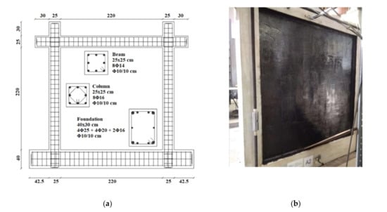
Figure 1.
(a) Dimensions of the RC frame and detailing of the internal steel reinforcement and (b) specimen A2R with FRPU jacket on the infill surfaces.

Table 1.
The dimensions of the RC frame and the detailing of the internal steel reinforcement.
Table 2.
Material properties of the infilled RC structure.
The two columns of the frame received a constant concentric axial load of 375 kN each. The horizontal actuator imposed successive pseudo-static cycles of gradually increased displacements at the top beam. More details on the materials used, the experimental setup, the instrumentation and test results of the A2R can be found in [25,35].
2.2. Seismic Protection of Infilled RC Structure with Highly Deformable Joints
2.2.1. Material Properties
A real-scale fully symmetrical one-story RC structure, consisting of masonry wall infilled RC frames (4 columns and 4 beams with a top slab), was subjected to shake table tests (see also Figure 2). The structure was designed according to current Eurocodes 2 and 8 [36,37]. The plane dimension of the structure was 3.8 × 3.8 m, and it was 3.3 m high. The material properties for the concrete, the reinforcing steel bars, the masonry (made of OrthoBlocks identical to the ones in A2R), the glass fiber grid and the PS polymer in the FRPU composite (FRPU identical to the one in A2R) are cited in Table 2. The structure was protected with 20 mm-thick polyurethane flexible joints (PUFJ) at the infill–RC frame interfaces made of PM polymer (mechanical properties are cited in Table 2). More details on the material properties can be found in [24].
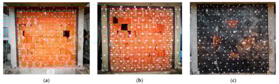
Figure 2.
Structure significantly damaged after PHASE 1: (a) north side—type B infill; (b) south side—type B infill; and (c) FRPU-strengthened infill of type B after PHASE 1.
2.2.2. Structure Detailing
The frames had floor plan dimensions of 2.7 × 2.7 m—based on the columns’ position—and a height of 2.5 m (to the top of the slab). The dimensions and longitudinal and transverse reinforcement detailing are cited in Table 3 and Table 4, respectively. The beam was hidden inside the slab. The 4 columns supported, on their top, an RC slab that was 200 mm thick. The slab carried carefully anchored steel ingots as additional masses (total 7200 kg) for the tested structure. The slab had a central square opening for access to the inside of the structure. The welded mesh top and bottom reinforcements of the slab are cited in Table 4. An additional slab reinforcement was placed at the perimeter edges and at the edges of the opening. The structure had a special foundation, with holes and hooks for attaching it to the shake table and for lifting and manipulating the structure (Figure 2a).
Table 3.
Dimensions of structure and of different parts.
Table 4.
Reinforcement detailing.
The infills in the building had a height of 2.3 m. Therefore, the ratio of the vertical (or horizontal) interface joint thickness to the infill wall height was 20/2300 = 0.0087. The infills were 100 mm thick, with holes in the vertical direction (identical to the ones in A2R). Out of the total of four infills, the two pairs of parallel walls had different seismic joint configurations to experimentally investigate the implementation of PUFJ in existing and new buildings. The two parallel infills of type B (Figure 2b) were constructed directly on the RC foundation with a 3 mm-thick mortar bed joint, while there was a PUFJ of 20 mm thickness, produced in situ through injection of polyurethane Sika PM. The polymer was injected between the infill and the RC columns, and between the infill and the RC slab (three-sided joint). The adhesiveness of Sika PM to brick substrates was determined equal to 0.63 MPa by a pull-off test in [38], followed by an adhesive brick/polymer failure mode. The two parallel infills of type C were constructed on a prefabricated 20 mm-thick PUFJ bottom joint (bonded to the RC foundation beam), while identical prefabricated joints were bonded at the sides and top of the infill (four-sided joint). The adhesiveness of Sika PS to brick substrates (used in FRPU) was determined by a pull-off test in [38] and was equal to 1.48 MPa, followed by an adhesive brick/polymer failure mode. More details on the detailing of the structure can be found in [24].
2.2.3. Loading Phases
Only PHASE 1 and PHASE 2 were considered for the numerical analysis. The original position of the model was such that both walls of type B were loaded in plane, and both walls of type C were loaded out of plane. In this position (PHASE 1), the structure suffered at least 10 dynamic earthquake runs of increasing maximum acceleration. The structure sustained a top slab relative displacement of 88.9 mm, corresponding to a 3.7% drift during the last run of PHASE 1. The damage to the infills of type B after the last run is depicted in Figure 2a,b. However, it should be noted that during that run, both brick infills of type B (tested in plane), protected by the PUFJ seismic joint, did not exhibit any significant damage up to a 2.5% drift of the structure. Both brick infills of type C (tested out of plane) had no significant damage after the last run of PHASE 1. After the first PHASE, the damaged brick infills of type B received FRPU external strengthening bonded on both sides of the damaged wall using a flexible adhesive of type Sika PS without any special treatment of the infill face and no crack repair (see Figure 2c). Then, three additional runs were performed during PHASE 2 up to a 1.62% drift of the structure. Further excitation during PHASE 2 was avoided in order to secure the integrity of the structure for PHASE 3 of the experiments (not presented herein) as the RC columns had already suffered significant damage. No additional significant damage to the infill walls of type B or to the infill walls of type C or any damage to the FRPU retrofit was observed after PHASE 2.
3. 3D FE Models
The numerical models were developed, and the material parameters were suitably calibrated based on the experimental parameters, using the Explicit Dynamics framework of the ANSYS Workbench [39] (see also [33,34]).
3.1. Geometry and Elements
RC members were modeled with solid elements for the concrete and linear elements for the reinforcement. Longitudinal steel bars and steel stirrups for columns, beams and slabs were modeled using the concept of “reinforcement” body interaction, not permitting separate reinforcement behavior. The parts for PUFJs were solid bodies with a 20 mm thickness, surrounding the 3 sides of the brick infill–RC frame interface for the type B infill and the 4 sides for the type C infill. Due to the small thickness of FRPUs, they were modeled as surface bodies to eliminate numerical instabilities and enhance the mesh quality. The body interaction between different components was considered as “bonded”. The model used the 8-node reduced integration hexahedral elements. These elements are suitable for dynamic applications including large deformations, large strains, large rotations and complex contact conditions in Explicit Dynamics. Linear 4-node tetrahedron elements are available for use in Explicit Dynamics analysis whenever hexahedral element meshing fails. Figure 3 shows the geometry of the FE models and mesh density.
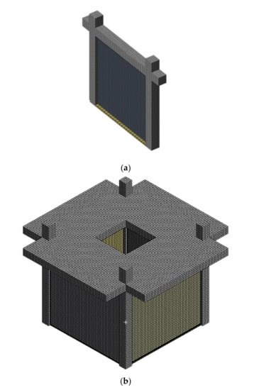
Figure 3.
Geometry and mesh of the (a) A2R frame and of (b) 4-column model of INMASPOL structure.
3.2. Material Models
The properties of the materials satisfied the experimental properties. PUFJs and glass FRPU were modeled as elastic materials. Concrete was of type RHT concrete, an advanced plasticity model for brittle materials developed by Riedel et al. [40,41,42]. The failure function for the RHT constitutive model, its fracture surface and the strain softening and damage relations of the model are gathered in Table 5.
Table 5.
RHT concrete model.
3.3. Boundary Conditions and Loads
The supports of the columns and infill had a fixed boundary condition. Pseudo-dynamic analyses of controlled monotonic displacement, imposed at the top of the structure (beam in A2R or at the top slab), were conducted to obtain the inelastic behavior of the A2R frame or of the structure for PHASE 1 and PHASE 2. The pseudo-dynamic pushover approach followed herein utilizes the advanced Explicit Dynamics features and minimizes the analysis time for demanding cyclic or dynamic tests (see also [33,34]).
4. 3D FE Analyses Results
4.1. A2R Frame
Figure 4 shows, in black and black-gray curves, the experimental envelope base shear–top displacement curves of A2R for (+) and (−) push, respectively, based on the results reported in [25,35]. The external application of the FRPU jackets on the OrthoBlock infill resulted in a remarkable top displacement ductility of the infilled frame A2R, with a negligible base shear reduction up to a 3.6% drift for push (+) and (−). Table 1 cites the experimental and numerical results of the A2R frame. The parameter used for the comparisons in this study is the absolute divergence (AD), also known as the absolute error (AE), and it is defined in Equation (10).
where a is the compared value (analytical or experimental).
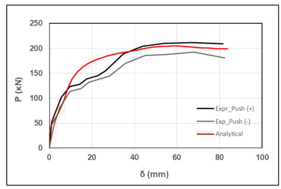
Figure 4.
Analytical base shear force–displacement curve for A2R, compared against the experimental ones.
The pseudo-dynamic analytical FE red curve coincides with the experimental ones up to 10 mm of top displacement, and then it falls in between the experimental curves for top displacement higher than 35 mm. The analytical maximum base shear is 204.7 kN (between the experimental push (−) and push (+)) at a top displacement of 59.1 mm, which is 9.1% lower than the experimental one. Satisfactory is the prediction of the ultimate base shear as well (Table 6). The divergence at the range of 10–35 mm top displacement may be attributed to the relatively rough modeling of the infill wall as a 3D panel.
Table 6.
Comparative results for A2R frame.
4.2. INMASPOL Structure
Based on the FE developments in RC frames and on the characteristics of the INMASPOL structure, three numerical models were developed and analyzed. The bare RC structure with no infills (model 1) was analyzed for comparison reasons. The response of analytical model 1 was compared against the response of the brick wall infilled structure with the innovative PUFJs (model 2, INMASPOL structure), as tested in PHASE 1. Then, the damaged brick wall infilled structure received external double-sided glass FRPU jacketing (model 3, corresponding to PHASE 2 shake table tests). The damage in model 3 was implemented by removing the continuous material from the infill walls, based on the observed infill type B wall damage after the end of the experimental PHASE 1 (see Figure 2a). That is, in model 3 the infill had selected 3D finite elements removed to simulate the locally damaged parts of the infill. Such approaches can also be found in the analytical investigation of the residual capacity of buildings with damaged infills or RC members in [43].
Figure 5a presents the diagrams of the experimental top slab accelerations (equivalent to the base shear divided by the excited mass of the structure) versus the relative drift of the top slab (relative top slab–column bottom displacement divided by the respective vertical distance) for each dynamic excitation of the structure on the shake table for PHASE 1, while Figure 5b shows these for PHASE 2. Herein, it should be noted that the results are reported in acceleration–drift terms, as in [20], and can be easily transformed to the equivalent base shear–top displacement terms.
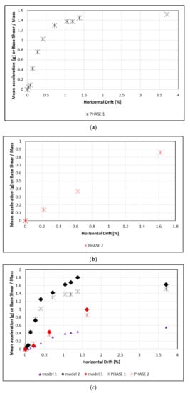
Figure 5.
Mean slab acceleration (or base shear/mass) versus horizontal drift diagram (a) for experimental PHASE 1; (b) for experimental PHASE 3; and (c) for numerical model 1, model 2 and model 3, against the experimental results of PHASE 1 and PHASE 2.
Figure 5c shows the results obtained from the pushover analyses in terms of top slab acceleration (base shear divided by the excited mass of the structure) versus the drift of the structure (relative top slab–column bottom displacement divided by the respective vertical distance).
The black star marks in Figure 5a,c show the experimental results from the shake table tests for the INMASPOL real-scale RC structure with OrthoBlock infills and PUFJ highly deformable seismic joints. The structure exhibits a ductile top acceleration–drift behavior which is equivalent to a ductile base shear–drift behavior. It reaches a 3.7% drift without degradation of the top acceleration (base shear). Figure 2a suggests there is no collapse of the infills tested in plane or out of plane after a 3.7% drift. Further, Figure 2c shows that the damage in infills of type B could be repaired with emergency FRPU external jackets without any special treatment of the infill (more details can be found in [20,24]).
The red star marks in Figure 5b,c show the experimental results from the shake table tests for the INMASPOL real-scale RC structure with OrthoBlock infills and PUFJ highly deformable seismic joints after the repair with FRPU (PHASE 2). The structure exhibits a rather linear elastic-like top acceleration–drift behavior which is equivalent to a linear elastic base shear–drift behavior. During retesting of the retrofitted structure, the achieved drift was 1.62% without degradation of the top acceleration (base shear). The FRPU maintained the integrity of the damaged infills, and collapse was also avoided in PHASE 2 (more details can be found in [20]). Interestingly, the stiffness of the repaired structure seems relatively increased, owing to the effects of the externally bonded FRPU jackets (more details can be found in [20]).
The abovementioned dynamic experimental results validate the advanced seismic protection provided by the 20 mm-thick PUFJ to the infill and the RC frame. An undesirable interaction is avoided, and the base shear drift behavior is remarkably ductile, while the potential of the structure is higher (tests at higher accelerations were avoided to prevent the structure from collapse and continue with PHASES 2 and 3). Similarly, the results in PHASE 2 validate the advanced retrofit of the infills by the FRPU jackets, and the potential of the structure is again higher.
Figure 5c also includes the FE analysis results for model 1 (triangles), for model 2 (black rhomb) and for model 3 (red rhomb). The developed models 2 and 3 compare well with the experimental results of the PHASE 1 and PHASE 2 tests. For model 2, the INMASPOL structure, in PHASE 1, at the initial stage of the acceleration–drift diagram, the behavior of the structure is elastic, and the experimental (black star marks) and analytical curves (black rhomb marks) coincide. After the stage of yielding of the steel bars of the concrete columns, the analytical curves start to overestimate the experimental points. The analytical acceleration value at a 3.7% drift slightly overestimates the corresponding experimental one. Overestimation of the experimental values by the analyses may be attributed to the higher damage accumulation in the RC columns and in the brick infills of type B during the experiments (the structure suffered a total of 10 earthquake excitations of increasing severity).
At PHASE 2, the analytical model was updated with the observed damage of the brick infill and with the retrofit with the FRPU (see the mesh in Figure 6a). The analytical values of model 3 (red rhomb) slightly overestimate the experimental ones (red star). The model reproduces the FRPU repair effects despite the local brick damage. Figure 6c reveals the engagement of broad infill regions (predamaged regions included) through the interaction with the highly deformable FRPU jacket and the RC frame.
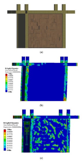
Figure 6.
(a) Mesh of the RC structure, of the damaged brick infill and of the external FRPU retrofit; (b) model 2 at the end of PHASE 1; and (c) model 3 at the end of PHASE 2.
Furthermore, the advanced FE analyses allow for a comparative investigation of the analytical response of the bare RC structure (model 1) against analytical models 2 and 3. The analyses in Figure 6 show that the bare structure sustains a maximum acceleration of around 0.55 g, while model 2’s and model 3’s maximum accelerations occurred at the end of PHASE 1 at around 1.63 g and 0.99 g, respectively. Therefore, the infilled structure with seismic protection developed a three times higher maximum acceleration (or base shear) than the bare structure at PHASE 1. The corresponding increase in the initial stiffness was similarly remarkable while maintaining the high displacement ductility (3.7% horizontal drift). At PHASE 2, the retrofitted structure still revealed a higher initial stiffness when compared with the bare structure, while it could develop, at least, around double the maximum acceleration (base shear). The area under the acceleration–drift curve (denoting a measure of the energy dissipation potential) is higher for model 2 (RC structure with infills protected with PUFJ joints) than for model 1 (bare RC structure). Therefore, in the case that the OrthoBlock infill with PUFJ protection is considered in the intervention for a weak bare RC frame, it can ensure a remarkable increase in the elastic stiffness and base shear while providing a desirable ductile P–δ behavior, with a drift as high as 3.7%.
4.3. FRPU Retrofitted INMASPOL Structure with the Addition of Steel Dowels
The developed 3D FE models allow for the analytical investigation of the FRPU retrofitted INMASPOL structure with additional mild intervention with steel dowels. Only five steel dowels were used at the top infill–RC beam boundary interface in order to increase the initial stiffness of the damaged structure, based on the approach proposed by Facconi and Minelli [44]. The steel connectors had a diameter of 16 mm and a length of 90 mm and consisted of a smooth-surface round bar made of structural steel having a nominal yield strength of 235 MPa. The distance between the five dowels was 410 mm (horizontal direction), while the middle dowel was placed at the middle of the beam span (no dowels in the vertical interfaces). This detailing avoids the position of the dowels within the corner beam–column regions that will increase their efficiency but will also increase the damage within the brick infill. As it is depicted in model 3, FRPU is efficient enough to maintain the integrity of the corner regions. The anchorage of the steel dowels in the reinforced concrete beam is 40 mm, and in the masonry wall, it is 50 mm. To increase the cohesiveness of the connection and to prevent early-stage damage, the area around dowels in the masonry was modeled with thixotropic mortar, as in [44].
Indeed, Figure 7 shows that at a 0.22% drift, the developed acceleration is 0.135 g for the revised model 3DOW with the additional steel dowels. Model 3 without dowels developed only 0.08 g acceleration (Figure 5c). The increase in the developed acceleration is 68% and reveals the earlier engagement of the infill. After a 0.6% drift, the accelerations for the two models almost coincide. Figure 8 reveals that the proposed dowel detailing leads to damage accumulation around the region within the brick infill in which the dowels are anchored. A vertical mode in controlled damage accumulation within the infill is denoted that coincides with the position of the five dowels. However, the interaction with the FRPU maintains the integrity of the infill. Based on the developed 3D FE models, the structure may receive a suitable combination of retrofits that could manipulate (in this case increase) the engagement of the infill and, correspondingly, the initial stiffness, if required. Further, the damage accumulation may be controlled in order not to lead to degradation in the performance of the structure.
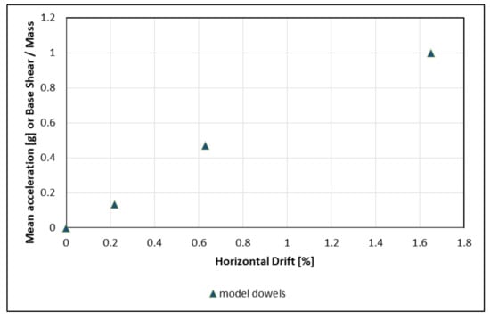
Figure 7.
Mean slab acceleration (or base shear/mass) versus horizontal drift diagram for the model 3DOW with additional steel dowels.
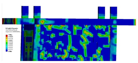
Figure 8.
Damage accumulation in model 3DOW at the end of PHASE 2 (upper part).
5. Conclusions
The developed 3D FE analytical models provide satisfactory predictions of the experimental P–δ response of the RC frame A2R with infills and FRPU jacketing. Similarly, satisfactory are the predictions for the experimental top acceleration–drift response of the INMASPOL structure having seismic protection through PUFJs in PHASE 1 and then retrofitting with FRPU jackets in PHASE 2.
The external application of double-sided FRPU jackets on the OrthoBlock infill resulted in a remarkable top displacement ductility of the infilled RC frame A2R, with a negligible base shear reduction up to a 3.6% drift for push (+) and (−). FRPU jackets with highly deformable polyurethane impregnation resin may maintain an adequate bond with the surrounding RC frame. Further, they maintain an adequate bond with the brick infill substrate. In all cases, FRPU jacketing ensured the integrity of the infill and of the jacket, excluding total or partial collapse of the infill or of smaller parts.
The INMASPOL real-scale RC frame possesses a low base shear capacity and a high ductility to satisfy the aims of the shake table tests: (a) carry enough mass to lead the real-scale infilled structure to in-plane infill failure and allow for the investigation of the infill contribution at high ductility levels and up to failure; (b) suffer specially designed severe excitation for the out-of-plane performance of the infills. The real-scale RC structure with OrthoBlock infills and PUFJ highly deformable seismic joints exhibited a ductile top acceleration–drift behavior (which is equivalent to a ductile base shear–drift behavior) up to a 3.7% drift, without degradation of the top acceleration (base shear). No collapse of the infills tested in plane or out of plane after a 3.7% drift was evidenced. The damage to infills of type B could be repaired with emergency FRPU external jackets without any special treatment of the infill. After its emergency repair with FRPU (PHASE 2), the structure exhibited a rather linear elastic-like top acceleration–drift behavior (equivalent to a linear elastic base shear–drift behavior) up to 1.62%, without degradation of the top acceleration (base shear). The FRPU maintained the integrity of the damaged infills, and collapse was avoided. The abovementioned dynamic experimental results validate the advanced seismic protection provided by the 20 mm-thick PUFJ to the infill and the RC frame. An undesirable interaction was avoided, and the base shear drift behavior was remarkably ductile, while the potential of the structure was expected to be higher (tests at higher accelerations were avoided to prevent the structure from collapse and continue with PHASES 2 and 3). Similarly, the results in PHASE 2 validate the advanced retrofit of the predamaged infills by the FRPU jackets, while the potential of the structure was expected, again, to be higher.
The advanced FE analyses allowed for a comparative investigation of the analytical response of the bare RC structure (model 1) against analytical models 2 and 3. The infilled structure with seismic protection developed a three times higher maximum acceleration (or base shear) than the bare RC structure at PHASE 1. The corresponding increase in the initial stiffness was similarly remarkable while maintaining the high displacement ductility, with a 3.7% horizontal drift. At PHASE 2, the FRPU retrofitted structure still revealed a higher initial stiffness when compared with the bare structure, while it could develop, at least, around double the maximum acceleration (base shear). Model 3 reproduced the FRPU repair effects despite the local brick damage. Broad infill regions (predamaged inregions cluded) were engaged through the interaction with the highly deformable FRPU jacket and the RC frame through the PUFJ. It seems that FRPU bridged the damaged brick infill areas and, together with the PUFJ, succeeded in causing a beneficial stress redistribution within the infill.
In the case the OrthoBlock infill with PUFJ protection is considered in the intervention for a weak bare RC frame, it can ensure a remarkable increase in the elastic stiffness and base shear while providing a desirable ductile P–δ behavior, with a drift as high as 3.7% (even after multiple earthquake excitations). Simultaneously, for the case under investigation, it prevents in- or out-of-plane collapse of the protected infills. Even if the structure suffers a drift as high as 3.7%, it may receive emergency retrofitting to maintain the integrity of the infill and increase its beneficial contribution to the RC frame.
The realization of a desirable ductile behavior of infilled frames through PUFJs of only 20 mm thickness (only 0.0087 of the height of the infill, compared with alternative proposals with detailing of 65 mm seismic joints or 90 mm sliding joints) and FRPU jacketing is of high importance. PUFJ, due to its high deformability and excellent bonding properties, constitutes a low-volume application (only 20 mm thickness of the joint) with simple detailing (only an interface layer). The application is straightforward in the retrofitting of existing walls (by injection) or in the construction of new walls with the use of prefabricated PUFJs. The polymer cures within hours (see [20]), and therefore it can serve as an emergency measure for retrofitting through injection or in new wall constructions (even with the construction of the prefabricated joints in situ ready to be used). No shear key detailing is required to exclude out-of-plane failure of the infill. The simplicity of the detailing, the low volume and the fast curing, compared with alternative seismic joint solutions such as the abovementioned ones presented in [6,22,23], reveal this solution’s feasibility of practical application, economic advantages and fast full protection activation. Similarly, FRPU, due to the high-deformability polyurethane involved, can be applied without any prior treatment of the infill substrate, cures within hours and maintains the bond with the substrate despite extensive infill cracking during loading. Such advantageous alternatives may contribute to building collapse prevention as well as preventing in- and out-of-plane infill collapses. Both are common causes of detrimental human injuries or human loss during severe earthquakes. The developed FE models provided a unique insight on the variable interactions and effects of the innovative interventions and may serve as a solid basis for further analytical investigations such as the utilization of combined retrofits.
Author Contributions
Conceptualization, T.R.; investigation, T.R., V.V., T.F. and E.A.; writing—review and editing, T.R., V.V., T.F. and E.A.; supervision, T.R.; project administration, T.R.; funding acquisition, T.R., T.F. and E.A. All authors have read and agreed to the published version of the manuscript.
Funding
This research was co-financed by Greece and the European Union (European Social Fund-ESF) through the Operational Programme «Human Resources Development, Education and Lifelong Learning 2014–2020» in the context of the project “Advanced Material Retrofits of Infilled Framed Reinforced Concrete Structures with Predamages Against Collapse” (MIS 5050146).
Institutional Review Board Statement
Not applicable.
Informed Consent Statement
Not applicable.
Data Availability Statement
Not applicable.
Conflicts of Interest
The authors declare no conflict of interest.
References
- Mehrabi, A.B.; Benson-Shing, P.; Schuller, M.P.; Noland, J.L. Experimental evaluation of masonry-infilled RC frames. J. Struct. Eng. 1996, 122, 228–237. [Google Scholar] [CrossRef]
- Al-Chaar, G.; Issa, M.; Sweeney, S. Behavior of masonry-infilled nonductile reinforced concrete frames. J. Struct. Eng. 2002, 128, 1055–1063. [Google Scholar] [CrossRef]
- Almusallam, T.H.; Al-Salloum, Y.A. Behavior of FRP Strengthened Infill Walls under In-Plane Seismic Loading. J. Compos. Constr. 2007, 11, 308–318. [Google Scholar] [CrossRef]
- Akhoundi, F.; Lourenço, P.B.; Vasconcelos, G. Numerically based proposals for the stiffness and strength of masonry infills with openings in reinforced concrete frames. Earthq. Eng. Struct. Dyn. 2016, 45, 869–891. [Google Scholar] [CrossRef] [Green Version]
- Hak, S.; Morandi, P.; Magenes, G. Prediction of inter-storey drifts for regular RC structures with masonry infills based on bare frame modelling. Bull. Earthq. Eng. 2017, 16, 397–425. [Google Scholar] [CrossRef]
- Morandi, P.; Hak, S.; Magenes, G. Performance-based interpretation of in-plane cyclic tests on RC frames with strong masonry infills. Eng. Struct. 2018, 156, 503–521. [Google Scholar] [CrossRef]
- Huang, H.; Burton, H.V.; Sattar, S. Development and Utilization of a Database of Infilled Frame Experiments for Numerical Modeling. J. Struct. Eng. 2020, 146, 04020079. [Google Scholar] [CrossRef]
- Dawe, J.L.; Seah, C.K. Out-of-plane resistance of concrete masonry infilled panels. Can. J. Civ. Eng. 1989, 16, 854–864. [Google Scholar] [CrossRef]
- Angel, R.; Abrams, D.; Shapiro, D.; Uzarski, J.; Webster, M. Behavior of Reinforced Concrete Frames with Masonry Infills. Civil Engineering Studies: Structural Research Series. 1994. Available online: http://hdl.handle.net/2142/14210 (accessed on 15 May 2021).
- Walsh, K.Q.; Dizhur, D.Y.; Giongo, I.; Derakhshan, H.; Ingham, J.M. Effect of boundary conditions and other factors on URM wall out-of-plane behaviour: Design demands, predicted capacity, and in situ proof test results. SESOC J. 2017, 30, 57. [Google Scholar]
- Stavridis, A.; Koutromanos, I.; Shing, P.G. Shake-table tests of a three-story reinforced concrete frame with masonry infll walls. Earthq. Eng. Struct. Dyn. 2011, 41, 1089–1108. [Google Scholar] [CrossRef]
- Uva, G.; Porco, F.; Fiore, A. Appraisal of masonry infll walls efect in the seismic response of RC framed buildings: A case study. Eng. Struct. 2012, 34, 514–526. [Google Scholar] [CrossRef]
- Celarec, D.; Dolsek, M. Practice-oriented probabilistic seismic performance assessment of inflled frames with consideration of shear failure of columns. Earthq. Eng. Struct. Dyn. 2012, 42, 1339–1360. [Google Scholar] [CrossRef]
- Ruggieri, S.; Porco, F.; Uva, G.; Vamvatsikos, D. Two frugal options to assess class fragility and seismic safety for low-rise reinforced concrete school buildings in Southern Italy. Bull. Earthq. Eng. 2021, 19, 1415–1439. [Google Scholar] [CrossRef]
- Yuksel, E.; Ilki, A.; Erol, G.; Demir, C.; Karadogan, H.F. Seismic retrofitting of infilled reinforced concrete frames with CFRP composites. In Advances in Earthquake Engineering for Urban Risk Reduction; Wasti, S.T., Ozcebe, G., Eds.; Springer: Dordrecht, The Netherlands, 2006; pp. 285–300. [Google Scholar] [CrossRef]
- Altin, S.; Anil, Ö.; Kara, E.M.; Kaya, M. An experimental study on strengthening of masonry infilled RC frames using diagonal CFRP strips. Compos. Part B Eng. 2008, 39, 680–693. [Google Scholar] [CrossRef]
- Ozden, S.; Akguzel, U.; Ozturan, T. Seismic strengthening of infilled reinforced concrete frames with composite materials. ACI Struct. J. 2011, 108, 414–422. [Google Scholar] [CrossRef]
- Koutas, L.; Bousias, S.N.; Triantafillou, T.C. Seismic strengthening of masonry-infilled RC frames with TRM: Experimental study. J. Compos. Constr. 2014, 19. [Google Scholar] [CrossRef]
- Gams, M.; Tomaževič, M.; Berset, T. Seismic strengthening of brick masonry by composite coatings: An experimental study. Bull. Earthq. Eng. 2017, 15, 4269–4298. [Google Scholar] [CrossRef]
- Rousakis, T.; Ilki, A.; Kwiecień, A.; Viskovic, A.; Gams, M.; Triller, P.; Ghiassi, B.; Benedetti, A.; Rakicevic, Z.; Colla, C.; et al. Deformable Pol-yurethane Joints and Fibre Grids for Resilient Seismic Performance of Reinforced Concrete Frames with Orthoblock Brick Infills. Polymers 2020, 12, 2869. [Google Scholar] [CrossRef]
- Fardis, M.N. Design provisions for masonry-infilled RC frames. In Proceedings of the 12th World Conference on Earthquake Engineering, Auckland, New Zealand, 30 January–4 February 2000. [Google Scholar]
- Marinkovic, M.; Butenweg, C. Innovative decoupling system for the seismic protection of masonry infill walls in reinforced concrete frames. Eng. Struct. 2019, 197, 109435. [Google Scholar] [CrossRef]
- Butenweg, C.; Marinković, M. Damage reduction system for masonry infill walls under seismic loading. Bull. Earthq. Eng. 2018, 2, 267–273. [Google Scholar] [CrossRef]
- Rousakis, T. Brick walls Interventions with FRPU or PUFJ and of RC columns with FR in Brick-Infilled RC Structures with the use of Pushover Beam-Column Element Analysis and Pseudo-Dynamic 3D Finite Element Analysis. In Proceedings of the 17th International Brick and Block Masonry Conference from Historical to Sustainable Masonry (IB2MaC 2020), Krakow, Poland, 5–7 July 2020. [Google Scholar]
- Akyildiz, A.; Kwiecień, A.; Zając, B.; Triller, P.; Bohinc, U.; Rousakis, T.; Viskovic, A. Preliminary in-plane shear test of infills protected by PUFJ interfaces. In Proceedings of the 17th International Brick and Block Masonry Conference from Historical to Sustainable Masonry (IB2MaC 2020), Krakow, Poland, 5–7 July 2020. [Google Scholar]
- Karabinis, A.I.; Rousakis, T.C.; Manolitsi, G.E. 3D Finite-Element Analysis of Substandard RC Columns Strengthened by Fiber-Reinforced Polymer Sheets. J. Compos. Constr. 2008, 12, 531–540. [Google Scholar] [CrossRef]
- Rousakis, T.; Karabinis, A. Fiber Reinforced Polymer Confinement of Bridge Columns Suffering from Premature Bars’ Buckling–Strength empirical model. In Proceedings of the 34th International Symposium on Bridge and Structural Engineering, Venice, Italy, 22–24 September 2010. [Google Scholar]
- Yu, T.T.; Teng, J.G.; Wong, Y.L.; Dong, S.L. Finite element modeling of confined concrete-I: Drucker–Prager type plasticity model. Eng. Struct. 2010, 32, 665–679. [Google Scholar] [CrossRef]
- Hany, N.F.; Hantouche, E.G.; Harajli, M.H. Finite element modeling of FRP-confined concrete using modified concrete damaged plasticity. Eng. Struct. 2016, 125, 1–14. [Google Scholar] [CrossRef]
- Youssef, O.; El Gawady, M.A.; Mills, J.E. Displacement and plastic hinge length of FRP confined circular reinforced concrete columns. Eng. Struct. 2015, 101, 465–476. [Google Scholar] [CrossRef]
- Yuan, F.; Wu, Y.F.; Li, C.Q. Modelling plastic hinge of FRP-confined RC columns. Eng. Struct. 2017, 131, 651–668. [Google Scholar] [CrossRef]
- Triantafyllou, G.G.; Rousakis, T.C.; Karabinis, A.I. Effect of patch repair and strengthening with EBR and NSM CFRP laminates for RC beams with low, medium and heavy corrosion. Compos. Part B Eng. 2018, 133, 101–111. [Google Scholar] [CrossRef]
- Anagnostou, E.; Rousakis, T.; Georgiadis, N. Finite element analysis of deficient RC columns with square and rectangular section under pseudoseismic load and comparison with retrofit code predictions. In Proceedings of the ICCE-26 Conference, Paris, France, 15–21 July 2018. [Google Scholar]
- Fanaradelli, T.D.; Rousakis, T.C. 3D Finite Element Pseudodynamic Analysis of Deficient RC Rectangular Columns Confined with Fiber Reinforced Polymers under Axial Compression. Polymers 2020, 12, 2546. [Google Scholar] [CrossRef] [PubMed]
- Triller, P.; Kwiecien, A.; Bohinc, U.; Zajac, B.; Rousakis, T.; Viskovic, A. Preliminary in-plane shear test of damaged infill strengthened by FRPU. In Proceedings of the 10th International Conference on FRP Composites in Civil Engineering (CICE 2020/2021), Istanbul, Turkey, 8–10 December 2021. [Google Scholar]
- Eurocode 2: Design of Concrete Structures—Part 1-1: General Rules and Rules for Buildings; British Standard: London, UK, 2008.
- Eurocode 8. Design of Structures for Earthquake Resistance—Part 1: General Rules, Seismic Actions and Rules for Buildings; British Standard: London, UK, 2004.
- Kwiecień, A. Stiff and flexible adhesives bonding CFRP to masonry substrates—Investigated in pull-off test and Single-Lap test. Arch. Civ. Mech. Eng. 2012, 12, 228–239. [Google Scholar] [CrossRef]
- ANSYS® Academic Research, Release v 2021 R1. Available online: https://www.ansys.com/products/release-highlights (accessed on 15 May 2021).
- Riedel, W. Beton Unter Dynamischen Lasten: Meso- und Makromechanische Modelle und ihre Parameter; Fraunhofer-Institut für Kurzzeitdynamik, Ernst-Mach-Institut EMI, Freiburg/Brsg, Eds.; Fraunhofer IRB Verlag: Stuttgart, Germany, 2004; ISBN 3-8167-6340-5. [Google Scholar]
- Riedel, W.; Thoma, K.; Hiermaier, S.; Schmolinske, E. Penetration of Reinforced Concrete by BETA-B-500, Numerical Analysis using a New Macroscopic Concrete Model for Hydrocodes. In Proceedings of the 9th International Symposium, Interaction of the Effects of Munitions with Structures, Berlin, Germany, 3–7 May 1999; pp. 315–322. [Google Scholar]
- Riedel, W.; Kawai, N.; Kondo, K. Numerical Assessment for Impact Strength Measurements in Concrete Materials. Int. J. Impact Eng. 2009, 36, 283–293. [Google Scholar] [CrossRef] [Green Version]
- El Mezaini, N.S. Reserved Strength of Reinforced Concrete Buildings with Masonry Walls. Comput. Civ. Infrastruct. Eng. 2005, 20, 172–183. [Google Scholar] [CrossRef]
- Facconi, L.; Minelli, F. Retrofitting RC infills by a glass fiber mesh reinforced overlay and steel dowels: Experimental and numerical study. Constr. Build. Mater. 2020, 231, 117133. [Google Scholar] [CrossRef]
Publisher’s Note: MDPI stays neutral with regard to jurisdictional claims in published maps and institutional affiliations. |
© 2021 by the authors. Licensee MDPI, Basel, Switzerland. This article is an open access article distributed under the terms and conditions of the Creative Commons Attribution (CC BY) license (https://creativecommons.org/licenses/by/4.0/).