1. Introduction
MLDSB is a new type of suspension bearing which is mainly composed of electromagnetic suspension and auxiliary by hydrostatic force bearing. The bearing capacity is greatly enhanced, and the operation stability and service life can be effectively improved. It is suitable for hydroelectric power, deep-sea exploration, and other fields, especially the medium speed overloading, frequently starting.
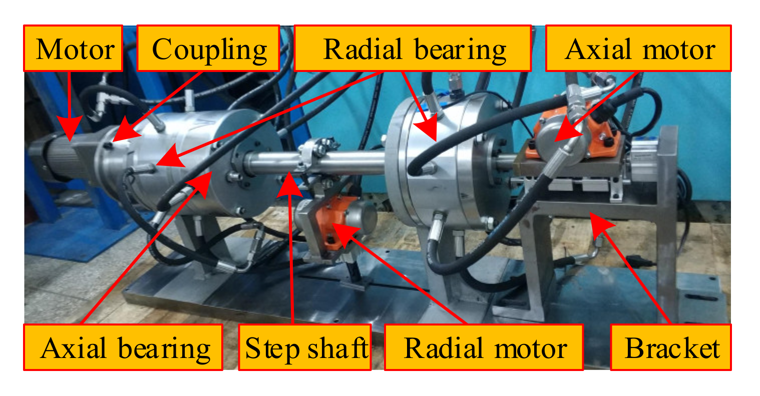
The structure of MLDSB test stand is composed of motor, coupling, radial bearing, axial bearing, axial motor, radial motor, step shaft, bracket as shown in
Figure 1.
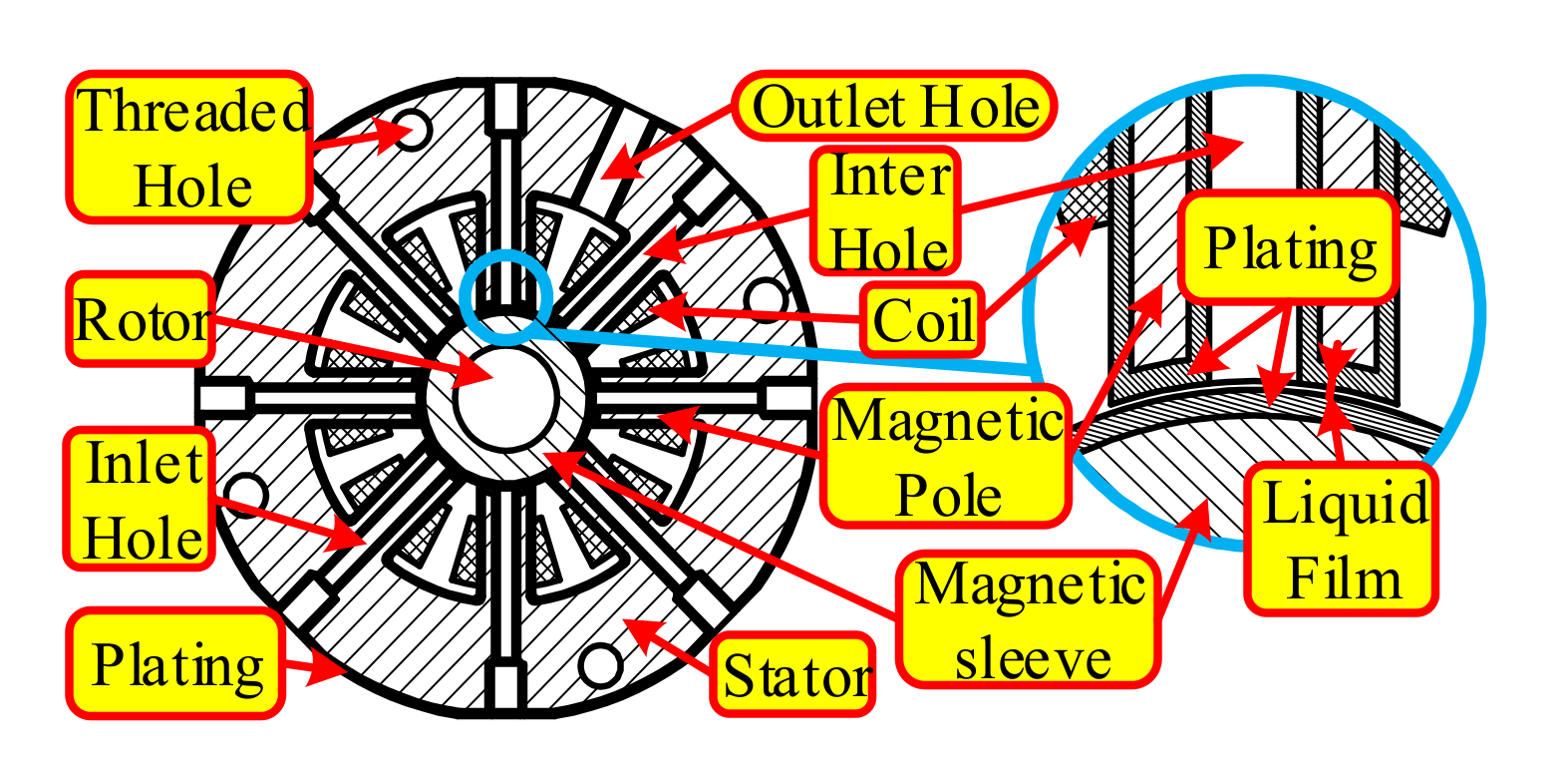
The radial unit of MLDSB is composed of rotor, magnetic sleeve, supporting chamber, magnetic pole, oil inlet/return hole, shell, coils as shown in
Figure 2. The poles and the magnetic sleeve are chrome-plated in order to protecting from corrosion by long-term immersion in oil. [
1,
2,
3].
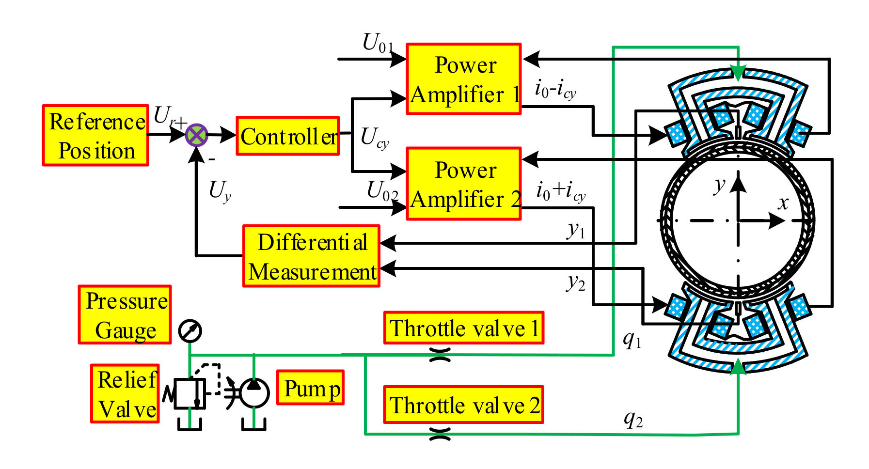
The regulation principle of MLDSB as shown in
Figure 3. PD control and constant pressure supply model are separately adopted in the electromagnetic system and hydrostatic system to realize real time regulation of the rotor [
4].
In the actual operation process, electromagnetic system failure [
5,
6] will be caused by electromagnetic coil corrosion and power amplifier circuit fault, which will lead to the phenomenon of “dropping-collision” between rotor and stator. The excessive wear, cracking, and shedding of magnetic sleeve and stator plating can be triggered, and the operational stability and reliability will be reduced.
In recent years, many scholars at home and abroad had studied the dropping phenomenon of rotor/bearing on system, and had achieved fruitful results.
Professor JARROUX [
7] investigated numerically and experimentally the rotor drop impact-rubbings when unexpected Active Magnetic Bearings (AMBs) shut down occurs. Rotor drop simulations in the time domain were carried out by using the Finite Unit method and the three TDB models. Predicted and measured rotor drop responses were compared regarding the displacements as well as transmitted loads and permits evaluating the model efficiency.
Professor PATPICK [
8] considered viable control methods that the magnetic bearing was still functional when contact arise from intermittent faults or overload conditions. The results demonstrated that appropriately phased synchronous forcing could destabilize synchronous forward rub responses. Alternatively, small whirl motions of a touchdown bearing could also be beneficial without disturbing the main magnetic bearing control loop.
Professor PESCH [
9] proposed a novel robust control strategy that is proposed for ensuring levitation recovery. The strategy utilized model based-synthesis to find the requisite AMB control law with unique provisions to account for the contact forces and to prevent control effort saturation at the large deflections that occur during levitation failure.
Professor Zhao [
10] established a detailed impact-rubbing model to reveal the behavior of the dropping rotor. Additionally, a PID control system for a magnetic bearing was designed with combination of contact possibilities. The control strategy mentioned in this paper was demonstrated theoretically as being effective in returning a rotor to the contact-free levitation position and avoiding further fierce contacts under several circumstances when external disturbance involved.
Professor Wang established a mechanical model for rotor drop and crash has been developed. A simulated rotor system was modeled by the finite unit method. The results showed that when the dropping at high speeds, if the kinematic energy of the rotor was not properly reduced, the rotor will whirl inside the backup bearings for a long time, introducing remarkable contact stress and deformation.
Professor Xu [
11,
12,
13,
14] studied the situation of self-eliminating clearance protection bearing after the failure of active electromagnetic bearing. Compared with the traditional roller bearing, a self-eliminating clearance protection bearing can significantly reduce the vibration of rotor falling behind and make the dropping of high-frequency speed more reliable.
Professor Jin [
15] studied the rotor orbits and the contact forces between rotor and inner race are simulated respectively after rotor drop on DDCBs (Double layer trap bearing) and SDCBs (Single layer trap bearing). The result shows that the rotor vibration range using DDCBs is significantly smaller than that using SDCBs. The maximum contact forces drop about 15%~27% compared with the contact forces using SDCBs. It is concluded that DDCB is helpful to reduce vibration amplitude and impact force.
Professor Jin [
16] studied the contribution of parameters such as unbalance; air gap, coefficient of friction, and coefficient of restitution to drop dynamics of the rotor are examined. When the unbalance is small, the resulting motion is also small. As the level of unbalance increases, the motion of the rotor becomes larger, so there is potential for damage to the rotor and the backup bearings.
Professor Zhu [
17] studied the transient nonlinear dynamic characteristics of a multi-disc rotor system when the rotor dropped on the standby bearing after the failure of the active electromagnetic bearing. The results show that the using of the bearing with large damping flexible structure can significantly improve the transient dynamic characteristics of the rotor dropping on the standby bearing, and reduce the impact of the rotor dropping on the life and reliability of the standby bearing.
Professor Jiang [
18] used ADAMS to model a new type of protective bearing, namely double-layer rolling bearing, and simulated the movement process of rotor drop in the bearing. The simulation results of rotor dropping trajectory and contact force show that double-layer rolling bearing can reduce the impact caused by rotor dropping.
To sum up, the traditional rotor drop-impact-rubbings study mainly focus on impact-rubbing characteristics and law of drop-in active electromagnetic bearing system under fault. Due to the coupling of the electromagnetic and hydrostatic system, the rotor “falling-rubbing” fault in the electromagnetic failure model is more complex. In addition, the traditional protective bearing is replaced by hydrostatic system, so that the “falling-rubbing” load can act directly on the plating of magnetic sleeve and pole. The excessive wear and fatigue cracking of magnetic sleeve and pole can be triggered, which seriously affects the operation stability and reliability of the MLDSB.
Therefore, single DOF dropping model of MLDSB is established in this paper to numerically simulate the influence of structure parameters (plating thickness and liquid film thickness), operation parameters (oil pocket pressure and bias current) on displacement of rotor, collision force, and supporting characteristics.
3. Numerical Simulation of Drop Process of Single DOF System
The initial design parameters of MLDSB are shown as
Table 1.
Simulation range of structure and operation parameters: h0 = (30~80) µm, l = (50~100) µm, i0 = (1~2) A, ps = (0.1~1.0) MPa.
3.1. Drop Impact-Rubbings Behavior of Upper Unit Failure Model
3.1.1. Influence of Structural Parameters on Rotor Impact-Rubbing Behavior
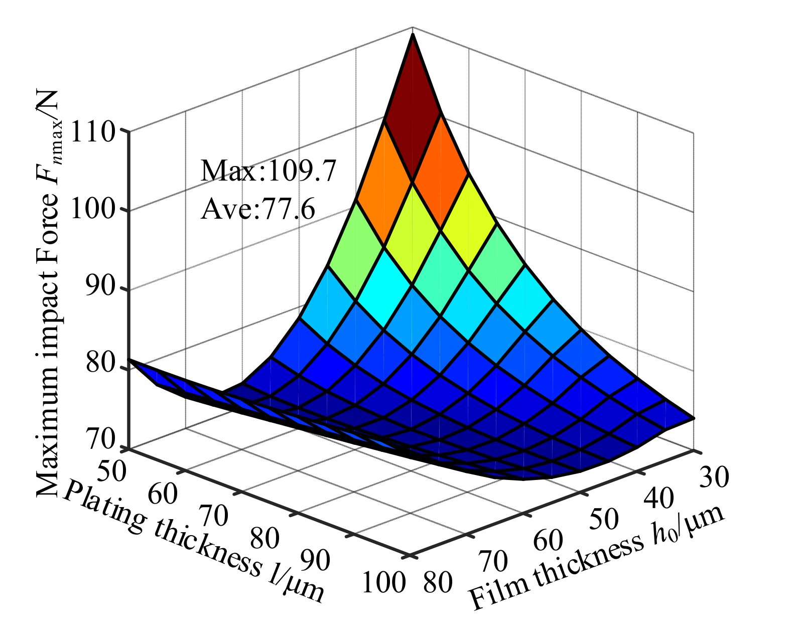
In the upper unit failure model, the maximum radial impact force of the rotor/stator collision varies with the structural parameters as shown in
Figure 4.
According to
Figure 4, the maximum radial impact force decreased firstly and then increased with the increase of liquid film thickness, and decreased with the increase of plating thickness. The maximum value occurs in the combination of
h0 is 30 µm and
l is 50 µm. Therefore, take it as the typical example in order to analyze the operation rules as shown in
Figure 5.
According to
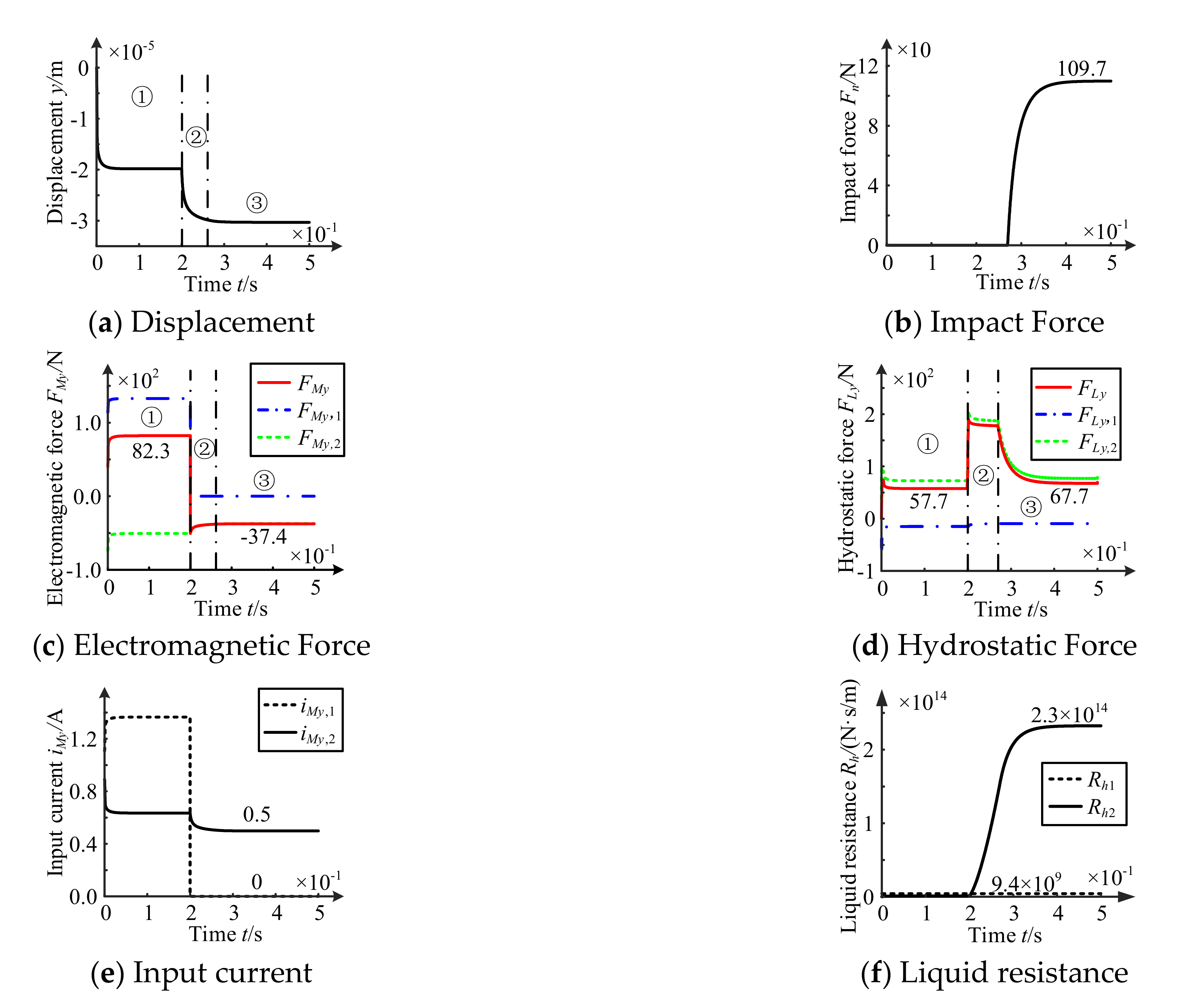
Figure 5, the upper unit failure occurs at
t = 0.2 s, and the motion of rotor includes three stages: initial equilibrium, dropping, and collision.
In initial equilibrium stage, the rotor is dropped from zero position and stays at −19.8 µm stalely. The load is borne by electromagnetic force and hydrostatic force as shown in Stage ①.
In dropping stage, the dropping speed of rotor decreases gradually. The current iMy,1 of supporting unit 1 decreases to 0 A, and the current iMy,2 of supporting unit 2 decreases, and then the electromagnetic force gradually approaches zero. The liquid resistance Rh1 of supporting unit 1 remains the same basically, but the liquid resistance Rh2 of supporting unit 2 rises rapidly due to the impact-rubbing damping effect of hydraulic oil. Therefore, the hydrostatic force increases rapidly first and then decreases slowly as shown in Stage ②.
In collision stage, the rotor reaches a new equilibrium state. As the contact depth between rotor and stator increases, the impact force Fn increases gradually, and the external load of the rotor is balanced with electromagnetic force FMy, hydrostatic force FLy, and impact force Fn. The current iMy,2 of supporting unit 2 decreases to 0.5 A, and the residual electromagnetic force FMy is −37.4 N. The liquid resistance Rh1 and the liquid resistance Rh2 are 9.4 × 10⁹ N·s/m and 2.3 × 10¹⁴ N·s/m respectively. However, the latter is about 2.4 × 10⁴ times than the former, resulting in a tiny tremor after a collision between rotor and stator. And the hydrostatic force FLy gradually reduced and finally stabilized to about 67.7 N as shown in Stage ③.
3.1.2. Influence Law of Operation Parameters on Rotor Impact-Rubbing Behavior
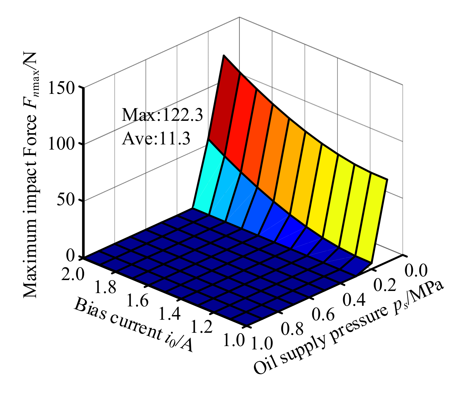
In this failure model, the maximum radial impact force of the rotor/stator collision varies with operation parameters as shown in
Figure 6.
According to
Figure 6, collision between rotor and stator is triggered when
ps < 0.3 MPa. Maximum radial impact force
Fnmax decreases with the increase of the oil pocket pressure and the decrease of the bias current. The maximum value appears when
ps = 0.1 MPa,
i0 = 2.0 A. Therefore, take it as a typical example in order to analyze operation rules as shown in
Figure 7.
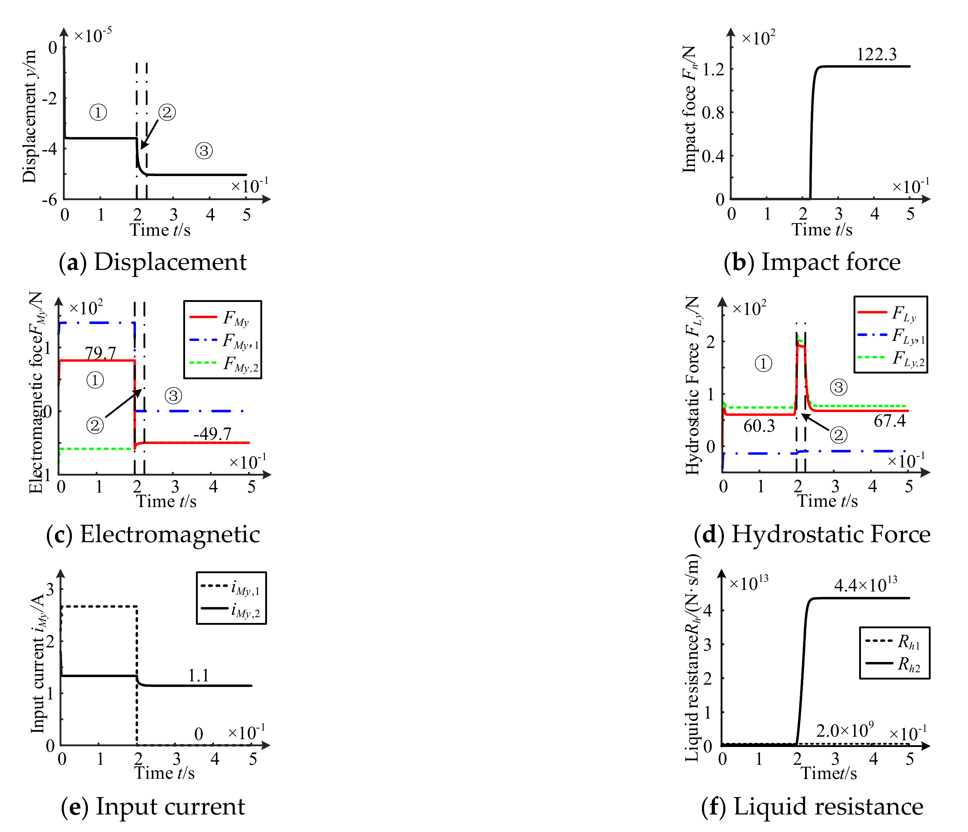
According to
Figure 7, in the initial equilibrium stage, the rotor drops from the zero position and stays at −35.9 µm, and the external load is borne by electromagnetic force and hydrostatic force as shown in Stage ①.
In dropping stage, the dropping speed of rotor decreases gradually. The current iMy,2 of supporting unit 2 decreases, and the residual electromagnetic force gradually approaches zero. The liquid resistance Rh2 of supporting pocket unit 2 increases rapidly due to the impact-rubbing damping effect of hydraulic oil. Therefore, the hydrostatic force increases rapidly first and then decreases slowly as shown in Stage ②.
In collision Stage, the rotor reaches a new equilibrium state. As the contact depth between rotor and stator gradually increases, the impact force Fn increases, and the external load of the rotor is borne by the electromagnetic force FMy and hydrostatic force FLy. The current iMy,2 of supporting unit 2 decreases to 1.1. In addition, the residual electromagnetic force FMy stabilizes to about −49.7 N. The liquid resistance Rh1 and liquid resistance Rh2 and are respectively stable at 2.0 × 10⁹ N·s/m and 4.4 × 10¹³ N·s/m. The latter is about 2.2 × 10⁴ times of the former, resulting in a tiny tremor after a collision between rotor and stator. The hydrostatic force FLy gradually decreases and stabilizes at about 67.4 N as shown in Stage ③.
3.2. Drop Impact-Rubbings Behavior of Lower Unit Failure Model
In lower unit failure model, the rotor/stator will not have collision within the range of selected structural parameters and operation parameters. A combination of
l = 50 µm,
h0 = 50 µm,
i0 = 1.0 A and
ps = 0.1 MPa was selected for analyzing as shown in
Figure 8.
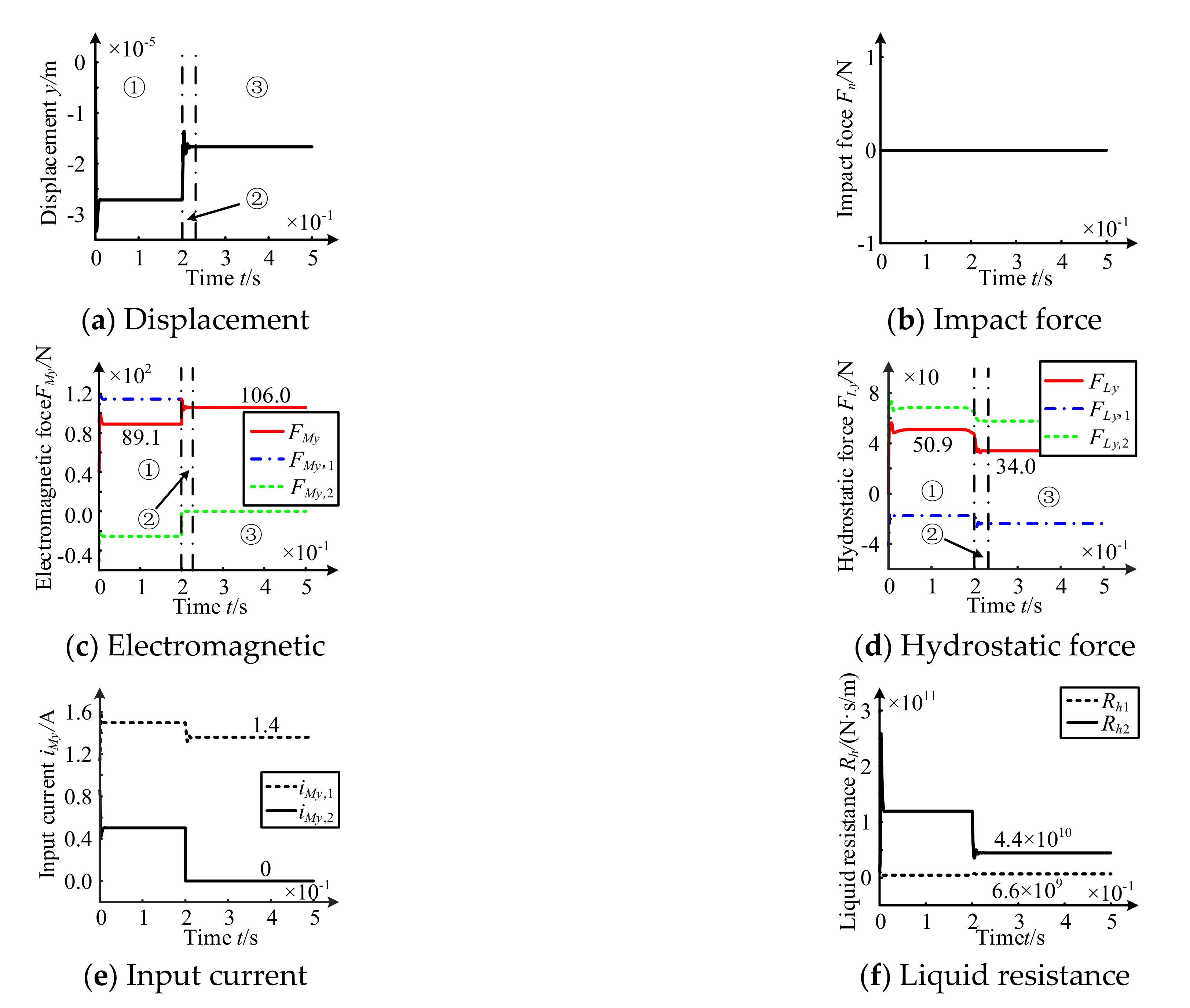
According to
Figure 8, in the initial equilibrium stage, the rotor dropped from the zero position and stays at −27.2 µm, and the load is borne by both electromagnetic force and hydrostatic force as shown in Stage ①.
In dropping Stage, rotor dropping direction upwards and close to zero. The current iMy,1 of supporting unit 1 decreases, while the current iMy,2 of supporting unit 2 decreases to 0. In addition, the resultant electromagnetic force increases. The liquid resistance Rh1 has little change. While the liquid resistance Rh2 has decreased due to the impact-rubbing damping effect of the oil. Moreover, hydrostatic force will be decrease as shown in Stage ②.
In final equilibrium Stage, rotor stabilizes at −16.7 µm. The current iMy,1 of the supporting unit 1 decreases to 1.4 A, leading to the electromagnetic force FMy,1 reducing. However, due to FMy,2 becomes 0, total electromagnetic force FMy rises to 106.0 N. The liquid resistance Rh1 and Rh2 are respectively stable at 6.6 × 10⁹ N·s/m and 4.4 × 10⁹ N· s/m. In addition, hydrostatic force FLy drops to 34.0 N. The rotor load is borne by both electromagnetic force and hydrostatic force as shown in Stage ③.
Compared with electromagnetic failure model of upper unit, the dropping behavior caused by this model does not cause rotor/stator collision. Therefore, it can be seen that the “fall-collision” under this model has little influence on bearing operation.
3.3. Drop Impact-Rubbings Behavior of Bilateral Failure Models
3.3.1. Influence Law of Structural Parameters on Rotor Impact-Rubbing Behavior
In bilateral failure model, the maximum radial impact force of rotor/stator collision varies with the structural parameters as shown in
Figure 9.
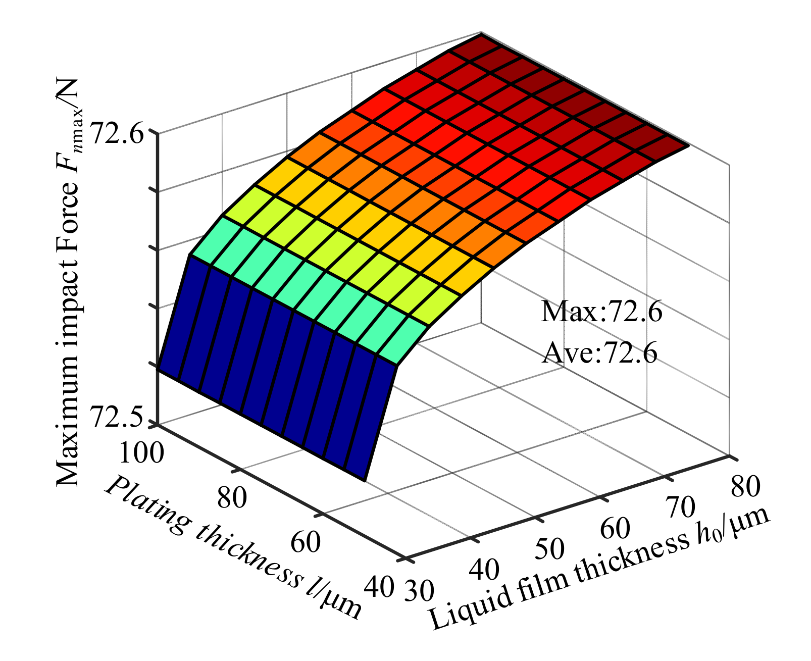
According to
Figure 9, maximum impact force
Fnmax changes very little within the range of selected structural parameters, ranging from 72.5 to 72.6. It will be invariable with the change of plating thickness, but increases with the increase of liquid film thickness. The maximum value of
Fnmax occurs in the combination of
h0 = 80 µm and
l = 50 µm. Therefore, take it as a typical example in order to analyzing operation rules as shown in
Figure 10.
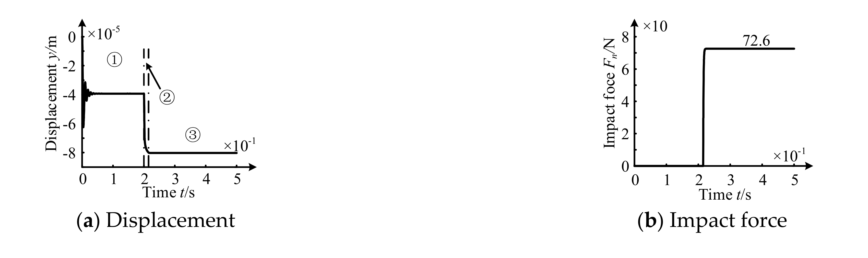
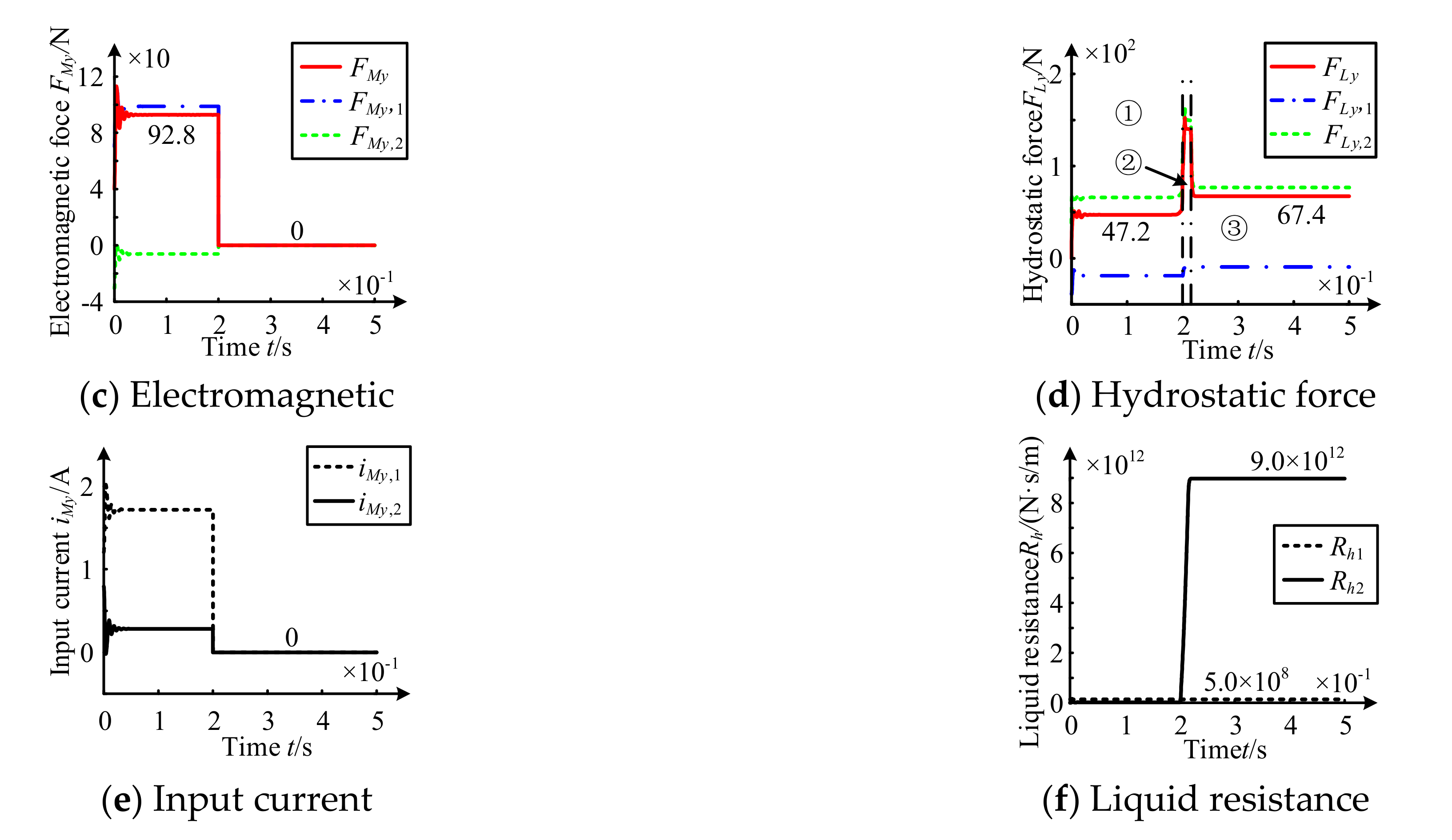
According to
Figure 10, in initial equilibrium stage, rotor dropped from zero position and stays at −39.3 µm after a small vibration. The load is borne by both electromagnetic force and hydrostatic force as shown in Stage ①.
In dropping Stage, rotor drops rapidly. The current iMy,1 of supporting unit 1 and the current iMy,2 decreases to 0, and electromagnetic force also becomes 0. The liquid resistance Rh1 has little change, while the liquid resistance Rh2 rises rapidly due to the impact-rubbing damping effect of oil. Therefore, the hydrostatic force increases rapidly first and then decreases slowly as shown in Stage ②.
In collision Stage, rotor reaches a new equilibrium state. As the contact depth between rotor and stator gradually increases, the impact force Fn increases, and the load of the rotor is borne by electromagnetic force FMy and hydrostatic force FLy. When electromagnetic system fails completely, and electromagnetic force FMy becomes 0. The liquid resistance Rh1 and Rh2 are respectively stable at 5.0 × 10⁸ N·s/m and 9.0 × 10¹² N·s/m. The latter is about 1.8 × 10⁴ times of former, resulting in a tiny tremor after a collision between rotor and stator. Moreover, hydrostatic force FMy decreases rapidly and finally stabilizes at about 67.4 N as shown in Stage ③.
Compared with upper unit failure, the variation of liquid film thickness and plating thickness does not affect the degree of rotor/stator collision. Dropping time is shorter, the stator/rotor contact arrives faster after collision Stage, the biggest impact force averages 72.6 N, less than upper unit failure model. Thus “fall-collision” effect on the bearing system is smaller under this model.
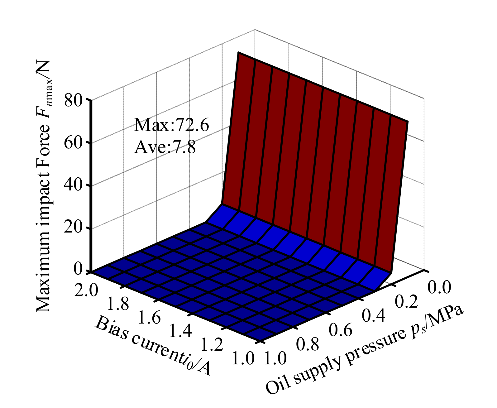
3.3.2. Influence Law of Operation Parameters on Rotor Impact-Rubbing Behavior
In this model, the maximum radial impact force of rotor/stator collision changes with operation parameters as shown in
Figure 11.
According to
Figure 11, rotor/stator collision is triggered when
ps < 0.3 MPa. Maximum radial impact force
Fnmax decreases with the increase of the oil pocket pressure and will be invariable with the change of the bias current. And its maximum value appears when
ps = 0.1 MPa. Therefore, take the combination of
ps = 0.1 MPa and
i0 = 2.0 A as a typical example in order to analyzing operation rules under this model as shown in
Figure 12.
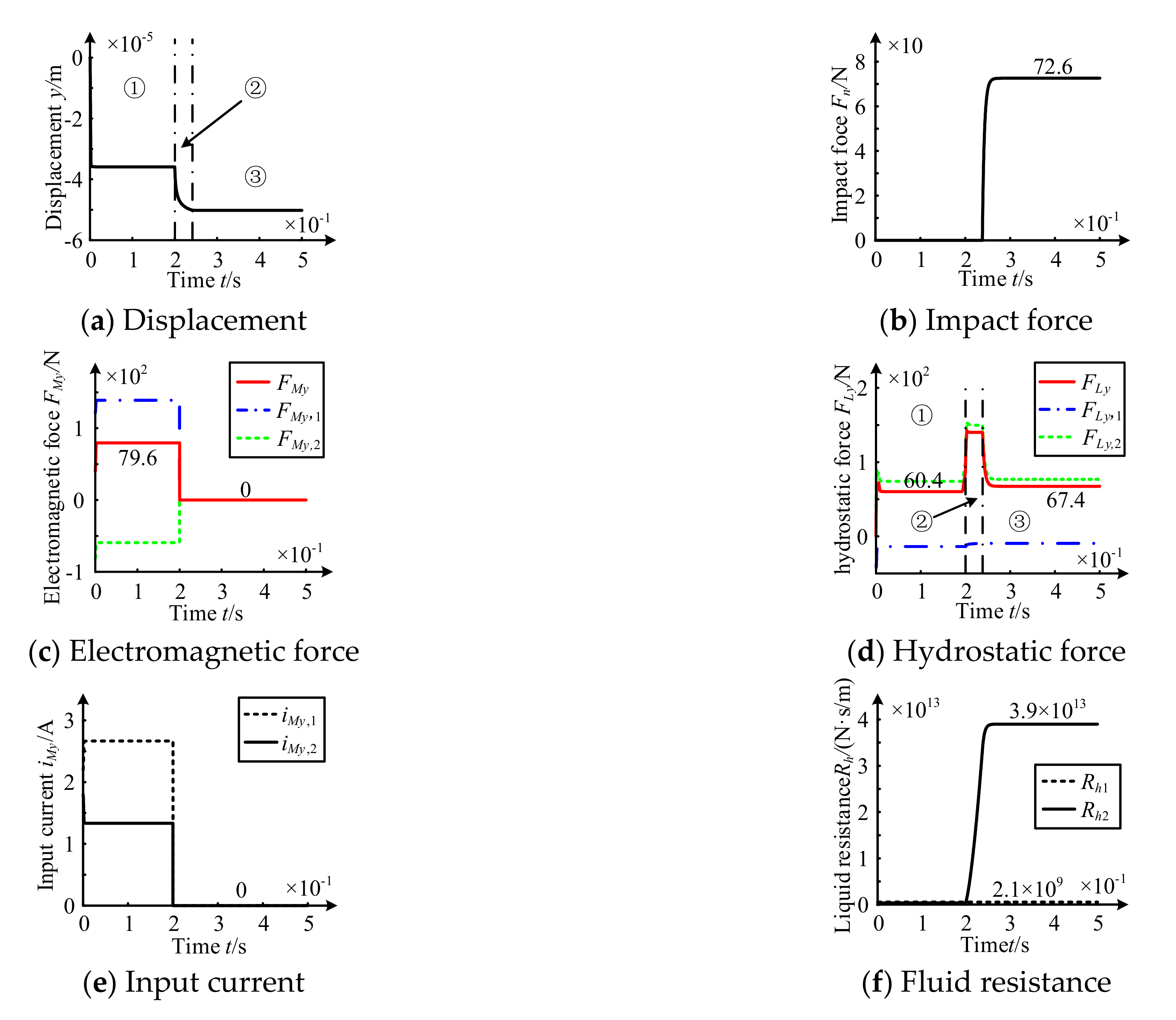
According to
Figure 12, the rotor dropped from the zero position and stays at −35.9 µm under initial equilibrium Stage. In addition, load is borne by electromagnetic force and hydrostatic force as shown in stage ①.
In dropping Stage, the dropping speed of rotor decreases greatly. With current iMy,1 and current iMy,2 decreases to 0, electromagnetic force also becomes 0. The liquid resistance Rh1 has little change, while the liquid resistance Rh2 rises rapidly due to impact-rubbing damping effect of oil. Therefore, the hydrostatic force increases rapidly first and then decreases slowly as shown in Stage ②.
In collision Stage, rotor reaches a new equilibrium state. As contact depth between rotor and stator gradually increases, the impact force Fn increases. In addition, the load of the rotor is borne by electromagnetic force FMy and hydrostatic force FLy. The electromagnetic system fails completely, and electromagnetic force FM becomes 0. The liquid resistance Rh1 and Rh2 are respectively stable at 2.1 × 10⁹ N·s/m and 3.9 × 10¹³ N·s/m. The latter is about 1.9 × 10⁴ times the former, leading to a tiny tremor after a collision between the rotor and stator. The hydrostatic force FMy rapidly decreases and finally stabilized to about 67.4 N as shown in Stage ③.
Compared with upper unit electromagnetic failure model, the variation of bias current will not affect the degree of collision. In the event of a collision area, the larger the oil chamber pressure is, the smaller the maximum radial impact force is. The mean of maximum radial collision force is 7.8 N, smaller than the 11.3 N of upper unit electromagnetic fails. Therefore the model of "fall-collision” effect on bearing system is smaller.
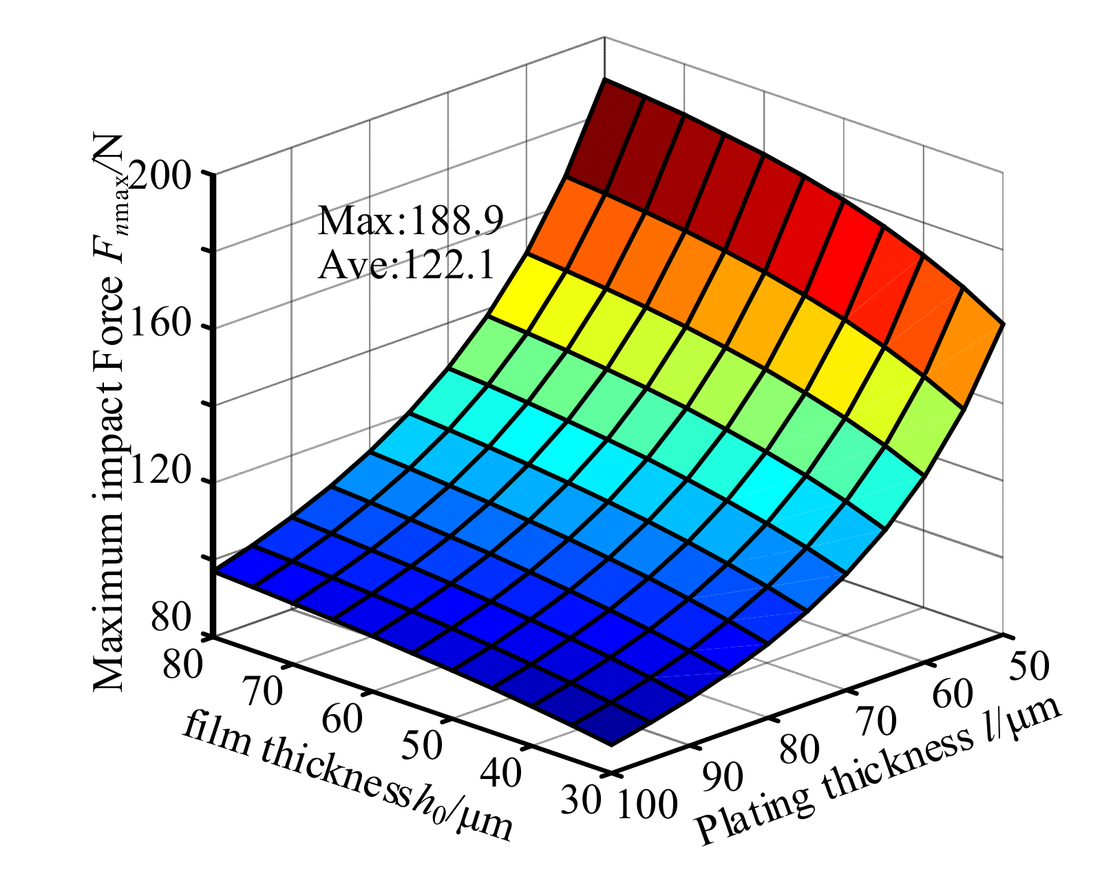
3.4. Drop Impact-Rubbings Behavior of Power Amplifier Failure Model
3.4.1. Influence Law of Structural Parameters on Rotor Impact-Rubbing Behavior
In failure model of power amplifier, the maximum radial impact force of rotor/stator collision changes with the structural parameters in the case as shown in
Figure 13.
According to
Figure 13, maximum impact force
Fnmax decreases with increase of plating thickness and increases with increase of liquid film thickness. Its maximum value occurs in the combination of
h0 = 80 µm and
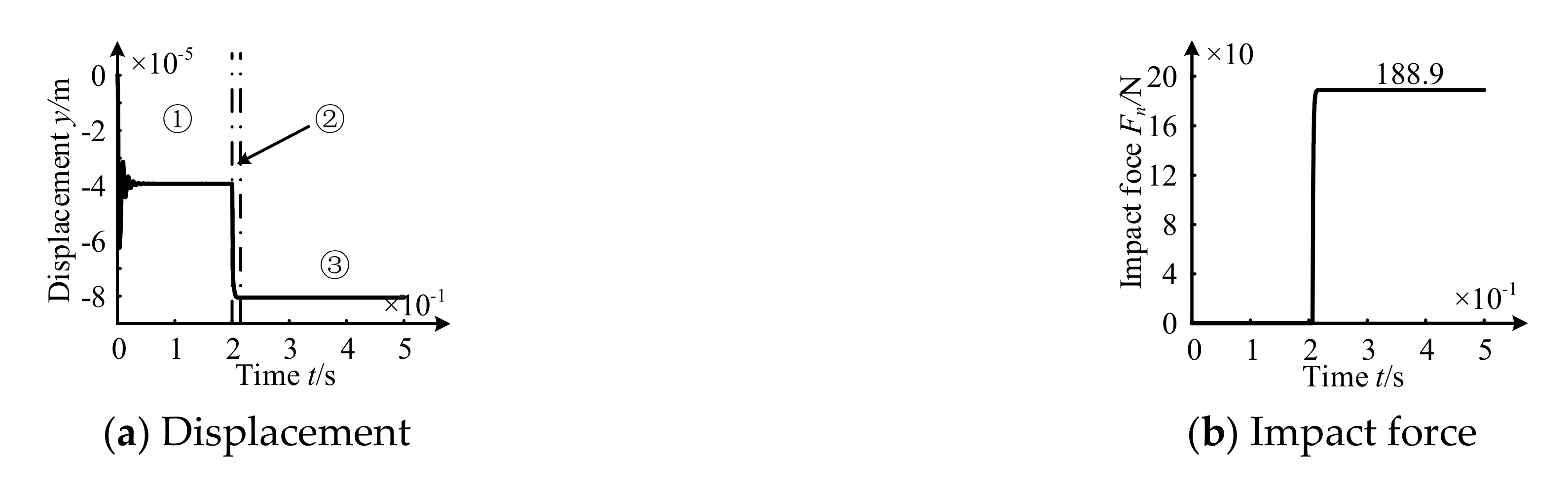
l = 50 µm. Therefore, take it as a typical example in order to analyzing operation rules under this model as shown in
Figure 14.
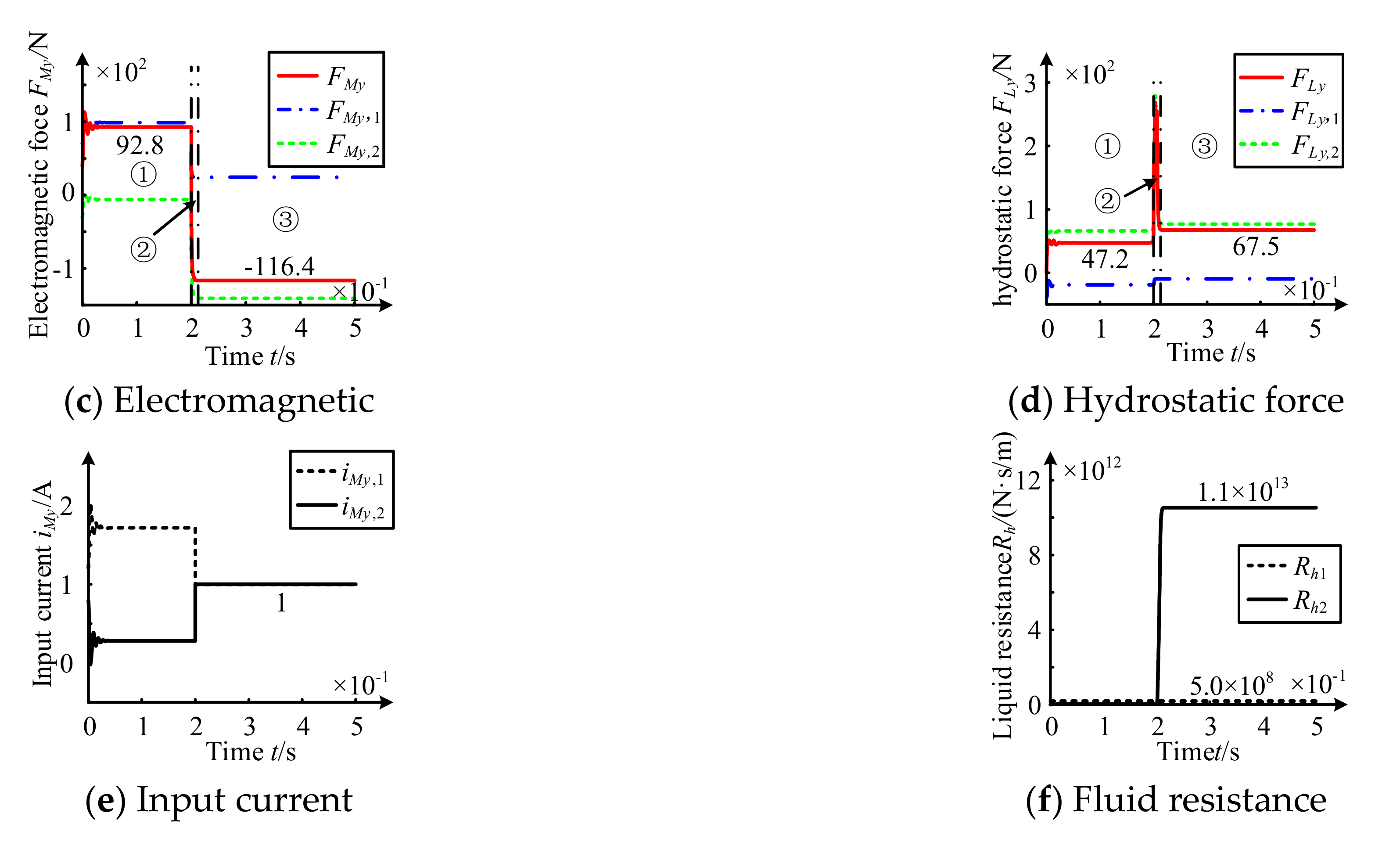
According to
Figure 14, in initial equilibrium Stage, rotor is dropped from zero position and stays at −39.3 µm after a small vibration. The load is borne by electromagnetic force and hydrostatic force as shown in Stage ①.
In dropping Stage, rotor drops rapidly. The current iMy,1 and iMy,2 become 1 A, and electromagnetic force decreases. The liquid resistance Rh1 has little change, while the liquid resistance Rh2 rises rapidly due to the impact-rubbing damping effect of oil. So that hydrostatic force rapidly increase as shown in Stage ②.
In collision Stage, rotor reaches a new equilibrium state. As the contact depth between rotor and stator gradually increases, the impact force Fn increases, and the load of the rotor is borne by electromagnetic force FMy and hydrostatic force FLy. The power amplifier failure, residual electromagnetic force FMy reduced to 116.4 N. The liquid resistance Rh1 and Rh2 are stable at 5.0 × 10⁸ N·s/m and 1.1 × 10¹³ N·s/m respectively. The latter is about 2.2 × 10⁴ times of the former, resulting in a tiny tremor after collision between rotor and stator. In addition, hydrostatic force FMy decreases rapidly and finally stabilizes to about 67.5 N as shown in Stage ③.
Compared with former three failure models, the liquid film thickness and plating thickness make the greater impact on the degree of collision. Moreover, the dropping time is the shortest, the rotor reaches the new equilibrium state more quickly after collision, and the mean value of maximum collision force is 122.1 N. In addition, the phenomenon of “dropping-collision” under this model have the greatest influence on operation of the bearing.
3.4.2. Influence Law of Operation Parameters on Rotor Impact-Rubbing Behavior
In this model, the maximum radial impact force of rotor/stator collision changes with the operation parameters as shown in
Figure 15.
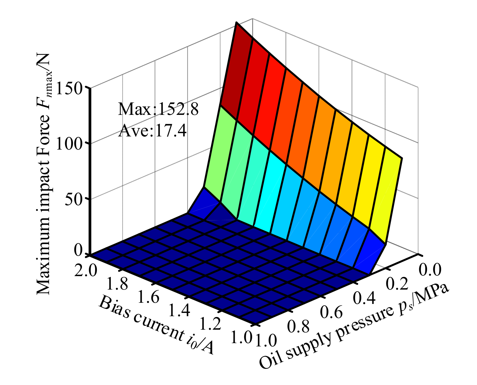
According to
Figure 15, maximum radial collision force
Fnmax decreases with the increase of oil pocket pressure, and with the decreases of bias current within parameter range of collision. Its maximum value appears in the combination of
ps = 0.1 MPa and
i0 = 2.0 A. Therefore, take it as a typical example in order to analyzing operation rule under this model as shown in
Figure 16.
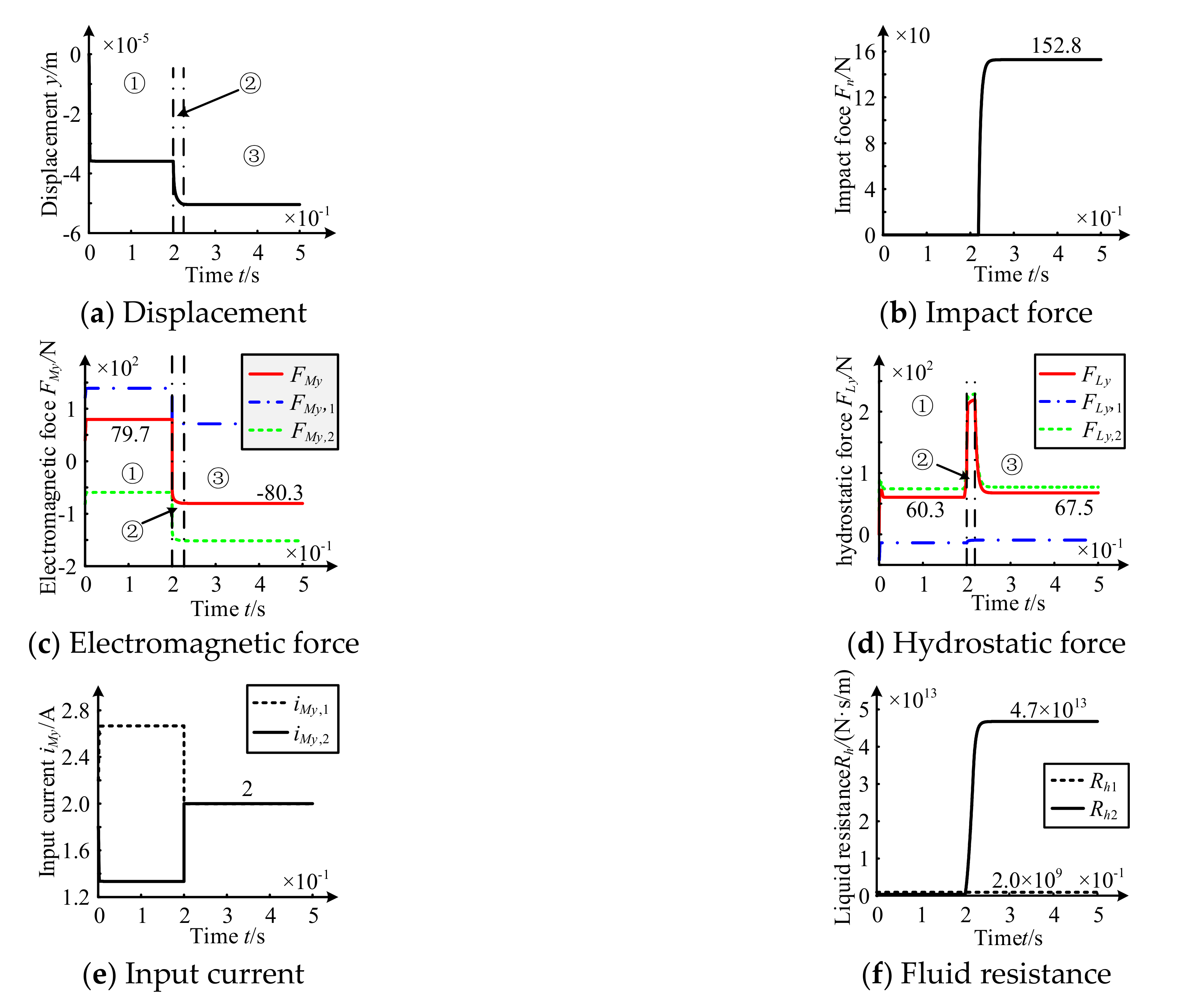
According to
Figure 16, in initial equilibrium Stage, rotor is dropped from zero position and stays at −35.9 µm. The load is borne by electromagnetic force and hydrostatic force as shown in Stage ①.
In dropping Stage, dropping speed of rotor decreases gradually. The current iMy,1 and iMy,2 change into 2 A, and the electromagnetic force decreases. The liquid resistance Rh1 has little change, but the liquid resistance Rh2 rises rapidly due to the impact-rubbing damping effect of oil. So that hydrostatic force rapidly increases as shown in Stage ②.
In collision Stage, rotor reaches a new equilibrium state. As contact depth between rotor and stator gradually increases, the impact force Fn increases. The load of the rotor is borne by the electromagnetic force FMy and the hydrostatic force FLy. When the power amplifier of the electromagnetic system fails, the electromagnetic force FMy decreases to −80.3 N. The liquid resistance Rh1 and Rh2 are respectively stable at 2.0 × 10⁹ N·s/m and 4.7 × 10¹³ N·s/m. The latter is about 2.4 × 10⁴ times of the former, resulting in a tiny tremor after collision between rotor and stator. And the hydrostatic force FMy rapidly decreases and finally stabilizes to about 67.5 N as shown in Stage ③.
Compared with the former three failure models, the oil pocket pressure and bias current have a greater influence on the degree of collision. And the dropping time is the shortest. The rotor contact reaches the new equilibrium state more quickly after a collision. And the mean of maximum collision force is 17.4 N. In addition, the phenomenon of “dropping-collision” under this model has the greatest influence on bearing operation.
4. Experimental Study on System Impact-Rubbings in Electromagnetic Failure Model
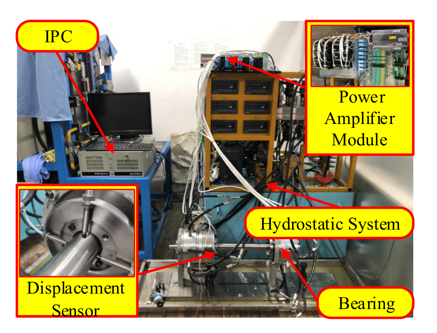
4.1. Construction of MLDSB Test Stand
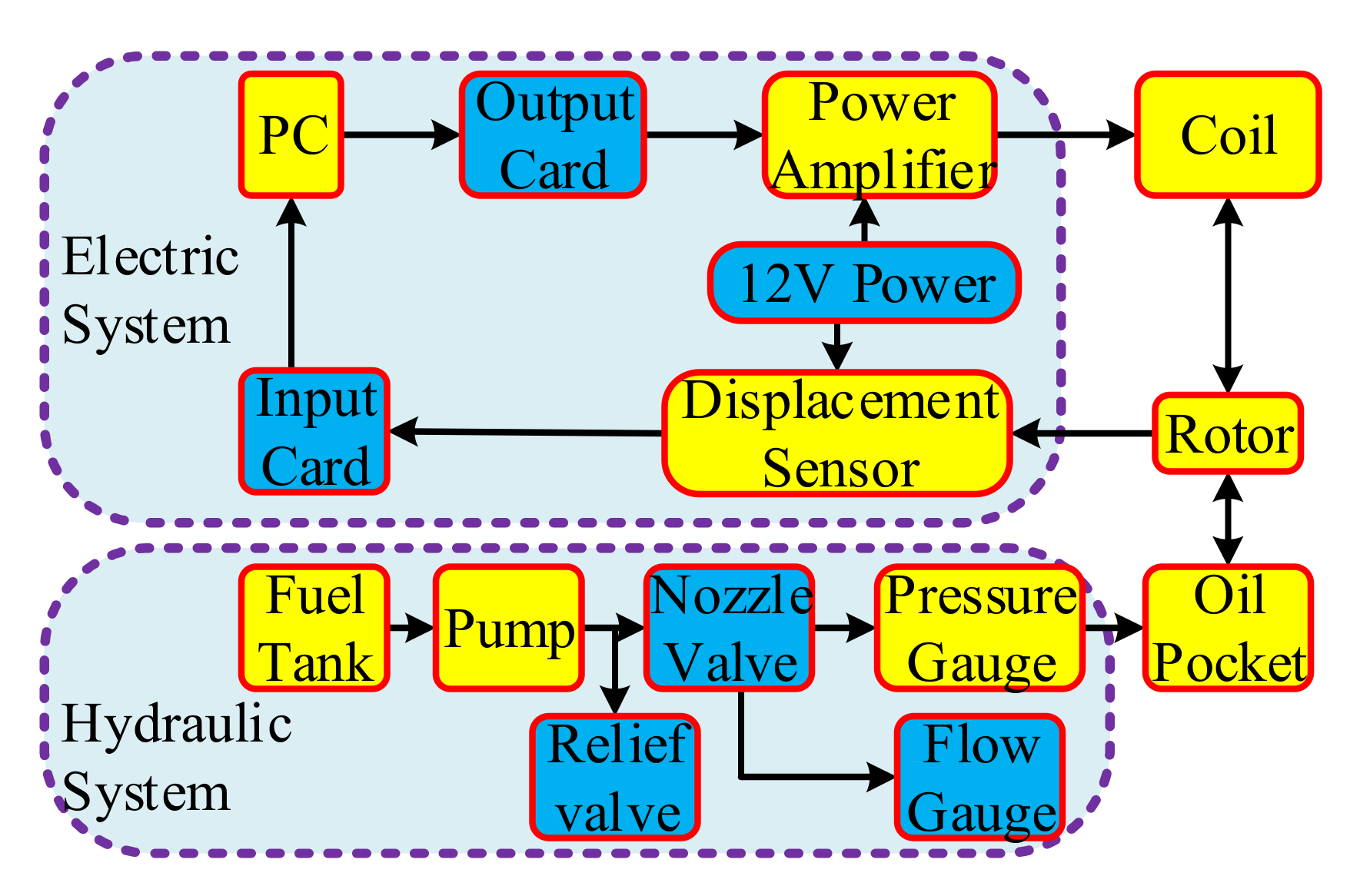
The MLDSB test stand is composed of the main body of the bearing, the electronic control system, the static pressure system, the displacement sensor, and IPC, as shown in
Figure 17.
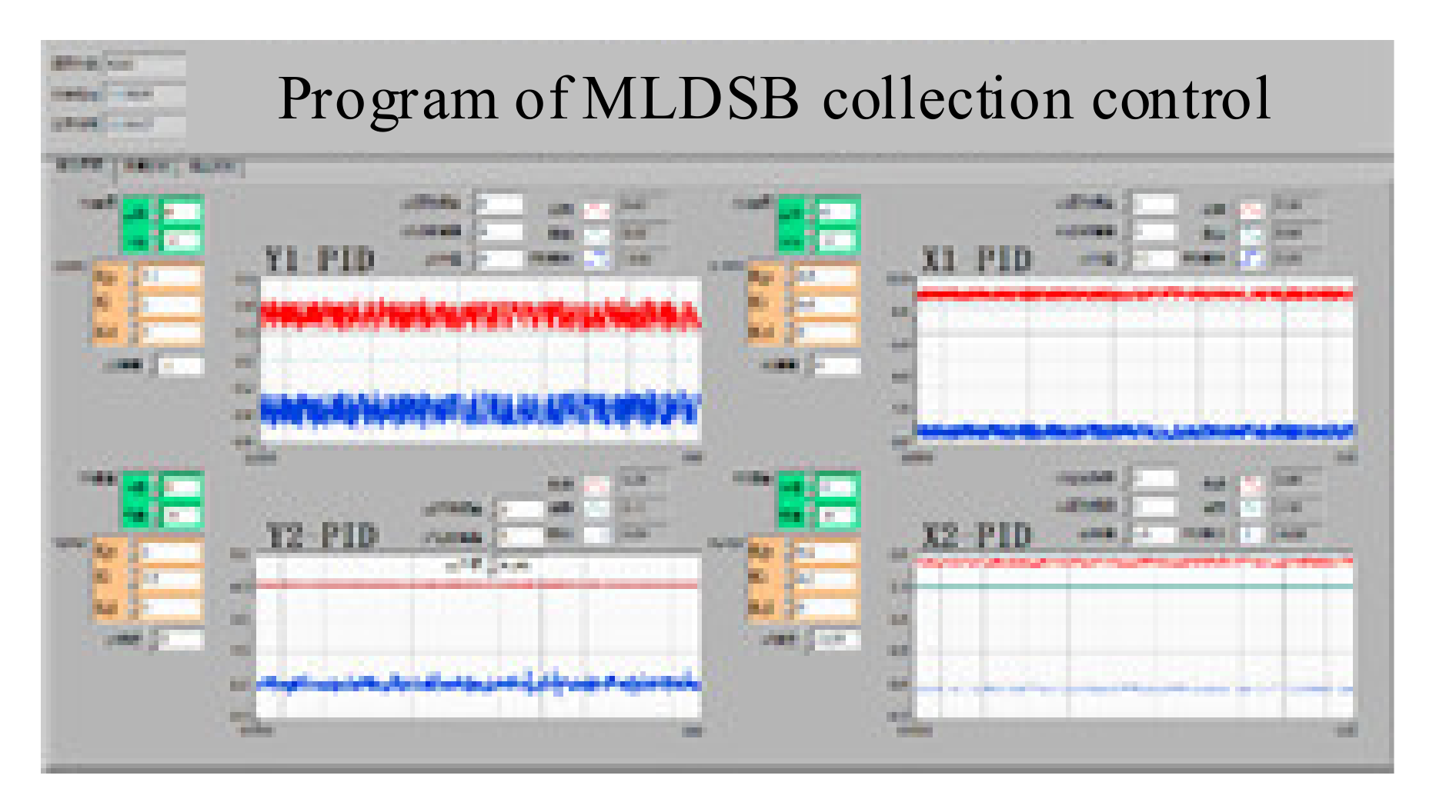
The schematic diagram of MLDSB test and interface of data acquisition and control are shown in
Figure 18 and
Figure 19.
4.2. Test Procedures
- (1)
Turn on the power, open on the oil pump, and operate the hydrostatic system.
- (2)
Adjust the output pressure of the needle valve.
- (3)
Operate the electromagnetic system, adjust the voltage deviation in order to suspense the rotor in the preset position;
- (4)
Input the PD parameter to adjust the voltage for the preset position of the rotor;
- (5)
Cut off the circuit of the upper unit in order to simulate the failure of the upper unit, and collect the signals of rotor displacement, oil pocket pressure, and voltage of coil.
- (6)
Similarly, cut off the circuit of the lower unit in order to simulate the failure of the lower unit, and collect the signals.
- (7)
Similarly, cut off the circuit of the upper and lower unit in order to simulate bilateral failure, and collect the signals.
- (8)
Set PD controller parameters to zero in order to simulate the failure of power amplifier, and collect the signals.
- (9)
Post treatment on stored data.
The initial parameters in the test and simulation are shown in
Table 2.
4.3. Rotor Dynamic Behavior under Failure of Upper Unit
The upper unit circuit is cut off, and the rotor dynamic behavior is tested as shown in
Figure 20.
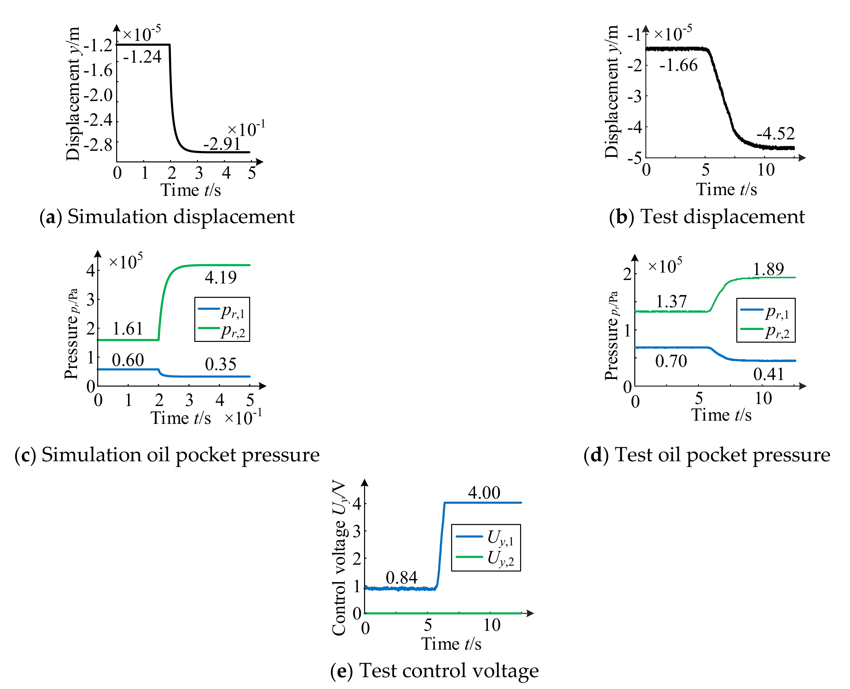
According to
Figure 20, when the electromagnetic system of the upper unit fails, the variation trend of rotor rubbing displacement obtained by experiment is basically consistent with the theoretical simulation. The theoretical value of rotor displacement ranges from −12.4 µm to −29.1 µm. The rubbing displacement is 16.7 µm and the rubbing time is 0.07 s. The experimental value ranged from −16.6 µm to −45.2 µm, the rubbing displacement is 28.6 µm, and the rubbing time is 4.21 s. The experimental rubbing displacement is 11.9 µm larger than that the theoretical value. The rubbing time is 4.14 s longer than that the theoretical value. This phenomenon is due to unilateral electromagnetic control adopted in the test stand and the phenomenon of oil leakage in MLDSB. It will lead to the speed of rubbing is smaller and the response time is longer.
When the upper unit fails, the pressure variation trend of the upper/lower oil obtained by experiment is basically consistent with the theoretical simulation. The theoretical value of upper pocket pressure pr,1 decreases from 0.060 MPa to 0.035 MPa. The experimental value decreases from 0.070 MPa to 0.041 MPa. The theoretical value of lower pocket pressure pr,2 increases from 0.161 MPa to 0.419 MPa. The experimental value increases from 0.137 MPa to 0.189 MPa. Because the final balance position of the rotor is lower than the initial position, the lower pocket pressure changes more than that of the upper pocket pressure.
In order to improve the stability of the electronic control system, the unilateral control strategy is adopted to the control voltage of the electromagnetic system on the test stand. The control voltage is only input to one of the upper or lower units, and the other side is only input to the bias voltage or no voltage input. Therefore, when the displacement sensor detects the gradual decline of the rotor, the upper unit continuously increases the regulation voltage to increase the electromagnetic attraction to prevent the rotor rubbing trend. As the electromagnetic coil circuit of the upper unit is manually disconnected, the electromagnetic attraction is zero, and the rotor keeps falling until the control voltage of the upper unit reaches the limit value of 4 V as shown in Figure 22e. Then the rotor continues to move down until the hydrostatic system balances the rotor and reaches the new balanced state again.
4.4. Rotor Dynamic Behavior under Failure of Lower Unit
The lower unit circuit is cut off, and the rotor dynamic behavior is tested as shown in
Figure 21.
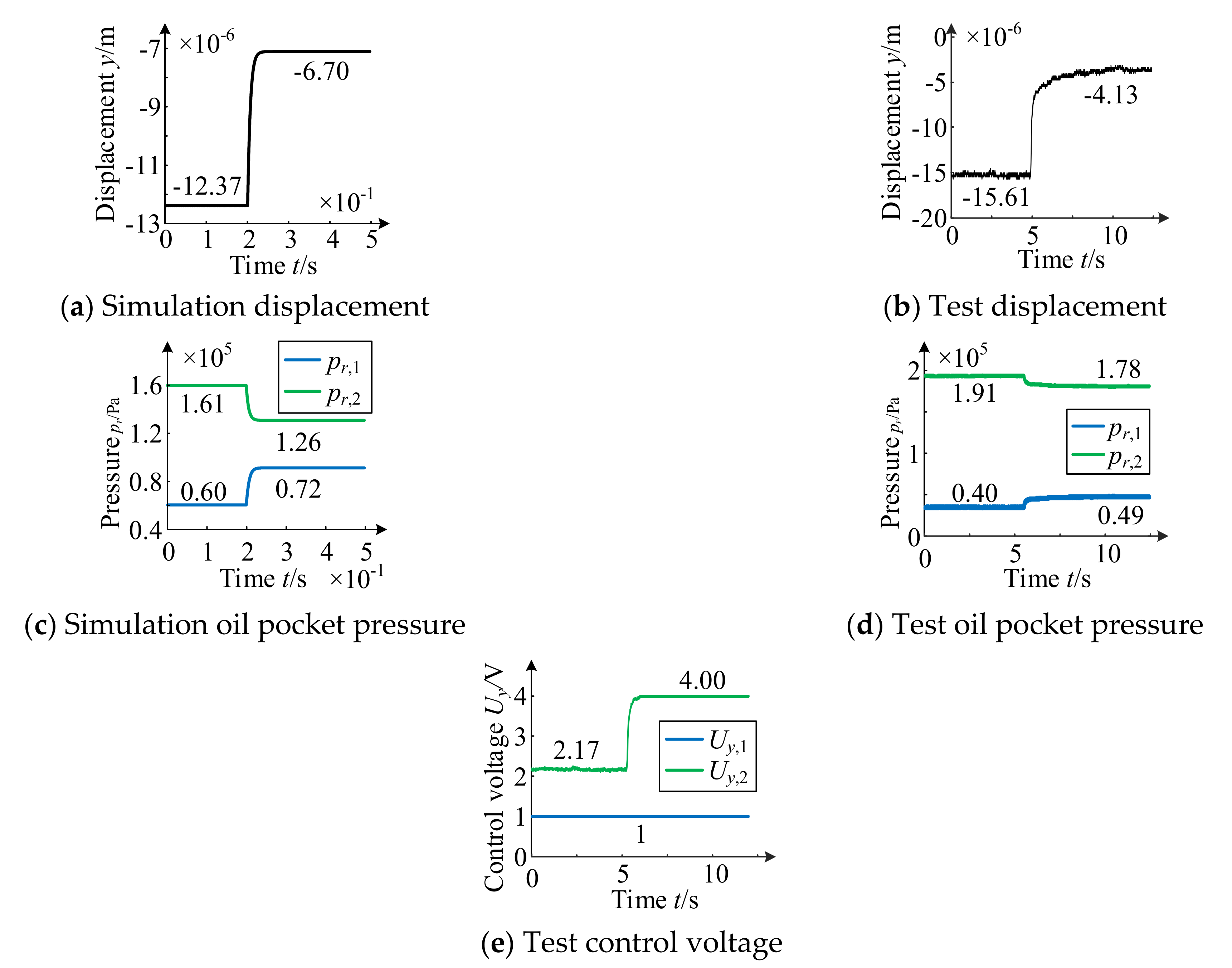
According to
Figure 21, when the electromagnetic system of the lower unit fails, the variation trend of rotor rubbing displacement obtained by experiment is basically consistent with the theoretical simulation. The theoretical value of rotor displacement ranges from −12.37 µm to −6.70 µm. The rubbing displacement is 5.67 µm and the rubbing time is 0.05 s. The experimental value ranged from −15.61 µm to −4.13 µm, the rubbing displacement is 11.48 µm, and the rubbing time is 1.26 s. The experimental rubbing displacement is 11.9 µm larger than that the theoretical value. The rubbing time is 4.14 s longer than that the theoretical value. The ascending displacement obtained from the test is 5.81 µm larger than the theoretical value. The ascending time is 1.21 s longer, accompanied by obvious tremor.
When the lower unit fails, the pressure variation trend of the upper/lower oil pocket obtained by experiment is basically consistent with the theoretical simulation. The theoretical value of upper pocket pressure pr,1 increases from 0.060 MPa to 0.072 MPa. The experimental value increases from 0.040 MPa to 0.049 MPa. The theoretical value of lower pocket pressure pr,2 decreases from 0.161 MPa to 0.126 MPa. The experimental value decreases from 0.191 MPa to 0.178 MPa.
When the lower unit fails, the rotor moves upward, and the control voltage Uy,2 gradually increases to its limit of 4 V, while the lower unit remains at 1 V.
4.5. Rotor Dynamic Behavior under Failure of Bilateral Unit
Cut off the circuit of the upper and lower unit, and the rotor dynamic behavior is tested as shown in
Figure 22.
According to
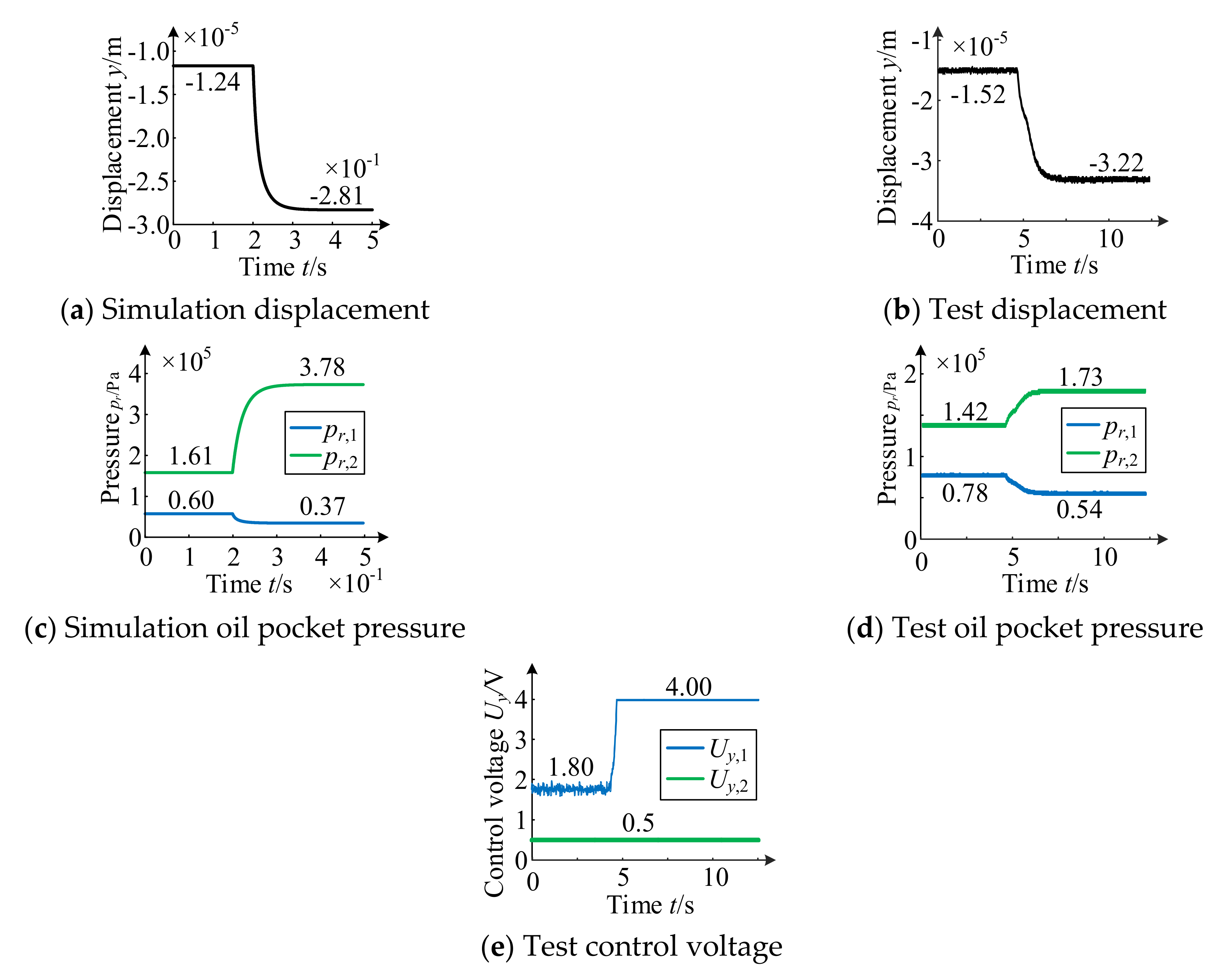
Figure 22, when the electromagnetic system of the bilateral unit fails, the variation trend of rotor rubbing displacement obtained by experiment is basically consistent with the theoretical simulation. The theoretical value of rotor displacement ranges from −12.4 µm to −28.1 µm. The rubbing displacement is 15.7 µm and the rubbing time is 0.06 s. The experimental value ranged from −15.2 µm to −32.2 µm, the rubbing displacement is 17.0 µm, and the rubbing time is 1.48 s. The experimental displacement is 1.8 µm larger than the theoretical value. The rubbing time is 1.42 s longer than the theoretical value.
When the upper unit fails, the pressure variation trend of the upper/lower oil pocket obtained by experiment is basically consistent with the theoretical simulation. The theoretical value of upper pocket pressure pr,1 decreases from 0.060 MPa to 0.037 MPa. The experimental value decreases from 0.078 MPa to 0.054 MPa. The theoretical value of lower pocket pressure pr,2 increases from 0.161 MPa to 0.378 MPa. The experimental value increases from 0.142 MPa to 0.173 MPa.
The control voltage and bias voltage are respectively inputted to the upper unit and lower unit. When the upper and lower circuits are opened, the control voltage of the upper unit increases to the limit of 4 V. While the output voltage of the lower unit remains at 0.5 V.
4.6. Rotor Dynamic Behavior under Failure of Power Amplifier
Set
Kp,
Kd of lower unit to zero, and the rotor dynamic behavior is tested as shown in
Figure 23.
According to
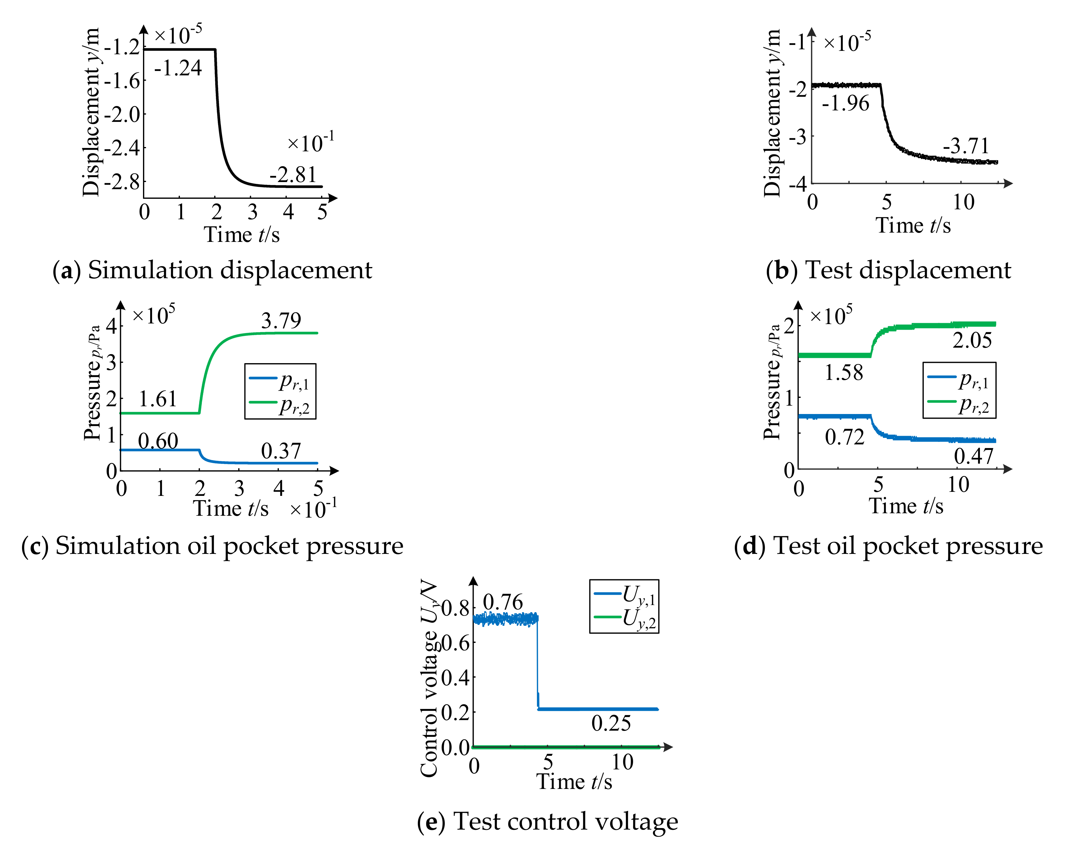
Figure 23, when the power amplifier fails, the variation trend of rotor displacement obtained by experiment is basically consistent with the theoretical simulation. The theoretical value of rotor displacement ranges from −12.4 µm to −28.1 µm. The rubbing displacement is 15.7 µm and the rubbing time is 0.05 s. The experimental value ranged from −19.6 µm to −37.1 µm, the rubbing displacement is 17.5 µm, and the rubbing time is 1.27 s. The experimental value is 1.8 µm larger than the theoretical value. The rubbing time is 1.22 s longer than the theoretical value.
When the power amplifier fails, the pressure variation trend of upper/lower oil pocket obtained by experiment is basically consistent with the theoretical simulation. The theoretical value of upper pocket pressure pr,1 decreases from 0.060 MPa to 0.037 MPa. The experimental value decreases from 0.072 MPa to 0.047 MPa. The theoretical value of lower pocket pressure pr,2 increases from 0.161 MPa to 0.379 MPa. The experimental value increase from 0.158 MPa to 0.205 MPa.
The control voltage is inputted to upper unit during the test. When it fails, the bias voltage is 0.25 V. Then the rotor continues to move down until the rotor is balanced by the hydrostatic system and reaches the new balance state.


 ,
, 


