Article

Theoretical Modeling of Piezoelectric Cantilever MEMS Loudspeakers

Key Laboratory of Modern Acoustics, Institute of Acoustics, Nanjing University, Nanjing 210093, China
*
Author to whom correspondence should be addressed.
Appl. Sci. 2021, 11(14), 6323; https://doi.org/10.3390/app11146323
Submission received: 17 June 2021 / Revised: 5 July 2021 / Accepted: 7 July 2021 / Published: 8 July 2021
(This article belongs to the Special Issue Sound Field Control)

Abstract

:
Piezoelectric microelectromechanical system (MEMS) loudspeakers have received extensive attention in recent years. In particular, the piezoelectric cantilever MEMS loudspeaker, which uses multilayer piezoelectric cantilever actuators (MPCAs), has attracted attention because of its small size, low cost, ease of manufacture, and desirable piston movement. However, owing to the complex driving principles of MPCAs, no adequately efficient and appropriate method currently exists that can be used to analyze and predict the performance of piezoelectric cantilever MEMS loudspeakers. In this study, the equivalent circuit method (ECM) is adopted to theoretically model piezoelectric cantilever MEMS loudspeakers, and an ECM model with a special MPCA transformer for electromechanical conversion is proposed. With the proposed ECM model, the performance characteristics of piezoelectric cantilever MEMS loudspeakers, such as the displacement and sound pressure response, can be calculated efficiently and conveniently. To verify the accuracy of the ECM model, the finite element method is adopted for simulation, and the simulated results are compared with those of the ECM models. A satisfactory agreement was found, which verifies the accuracy of the proposed ECM model.

1. Introduction

Compared to conventional electrodynamic loudspeakers, microelectromechanical system (MEMS) loudspeakers are considered to be more suitable for use in portable equipment applications owing to their higher energy efficiency [1] and smaller thickness. Among the different types of MEMS loudspeakers [1,2,3,4,5], piezoelectric MEMS loudspeakers have attracted attention because they require a low actuation voltage to provide a high actuation force [6] and are insensitive to dust [7].
Many previous studies have been devoted to analyzing the performances of piezoelectric MEMS loudspeakers. Early works focused on conducting measurements for the analysis of different types of piezoelectric MEMS loudspeakers. Ko et al. measured the displacement, sound pressure response, and sensitivity of a piezoelectric membrane, which works as both a microphone and an MEMS loudspeaker [8]. Cho et al. measured the sound pressure response of a piezoelectric MEMS loudspeaker fabricated with a ZnO thin film [9]. With the increasing capacity of numerical computations, the finite element method (FEM) has become a capable tool for the simulation of MEMS loudspeakers. Stoppel et al. utilized FEM simulations to study a novel type of MEMS loudspeaker featuring membrane-less two-way sound generation [10]. Cheng et al. employed an FEM simulation to predict and compare the performance of their proposed suspension-spring and dual-electrode designs [11]. Although FEM can predict the performance of MEMS loudspeakers precisely, it requires a large amount of mesh generation to ensure the accuracy of the simulation, which substantially increases the computational complexity and time consumption. In comparison with FEM, the equivalent circuit method (ECM) is more efficient. Liechti et al. analyzed a new type of MEMS loudspeaker accurately using ECM [12]. Wang et al. established an ECM model for MEMS loudspeakers using a piezoelectric circular plate [13], and the model facilitated fast numerical analysis via analytical solutions.
Recently, piezoelectric cantilever MEMS loudspeakers [14] have attracted increasing attention for portable audio applications because of their low cost and easy manufacturing procedure. They are driven by multilayer piezoelectric cantilever actuators (MPCAs) and exhibit piston vibration behaviors over a large surface. However, the existing ECM models cannot be applied to piezoelectric cantilever MEMS loudspeakers owing to the driving complexity of MPCAs. This significantly increases the difficulty of modeling and analyzing piezoelectric cantilever MEMS loudspeakers.
In this study, an efficient ECM model of the piezoelectric cantilever MEMS loudspeaker with a special transformer suitable for MPCAs is presented. Based on theoretical analysis and derivation, a new transformer for MPCAs to achieve electromechanical conversion is proposed, which is required to establish the ECM model. FEM models with varying levels of complexity are used to validate the ECM model in three cases. Case 1 verifies the analytical solutions of a single MPCA, while cases 2 and 3 corroborate the feasibility of using the ECM model with the special transformer for different structures using paired MPCAs.
This paper is organized as follows: Section 2 introduces the piezoelectric cantilever MEMS loudspeaker, proposes a special transformer, and presents an ECM model. Section 3 employs the FEM models in three aforementioned cases for validation. Section 4 concludes the paper.

2. Theoretical Modeling of Piezoelectric Cantilever MEMS Loudspeaker Using ECM

A schematic of a piezoelectric cantilever MEMS loudspeaker is shown in Figure 1. The middle coupling element is used to connect the MPCAs and the diaphragm. Multiple pairs of MPCAs and a diaphragm are coupled via a middle coupling element in order to exhibit piston vibration behaviors over the diaphragm. The MPCAs are clamped on one end and applied by a force from the middle coupling element on the other end. When a voltage is applied, the MPCAs vibrate and push the diaphragm to radiate sound. The surround generates a restoring force during the vibration process. A closed back cavity is used to avoid acoustic shortcuts.

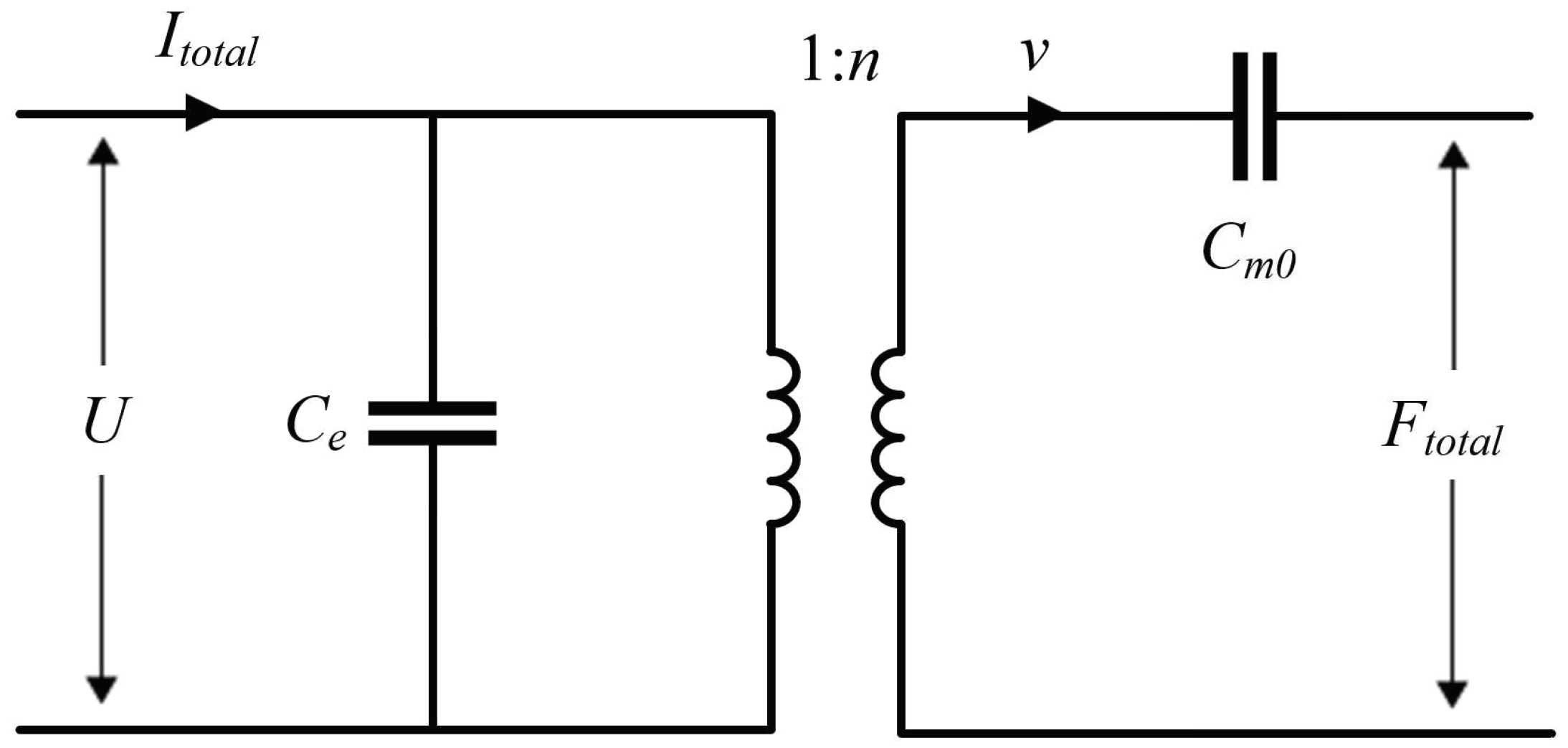
2.1. Transformer for Multiple Pairs of MPCAs

As MPCAs are symmetrically distributed, it can be considered that the force of each MPCA acting on the middle coupling element is equal, and the motion of each MPCA is, therefore, the same. Then, the analytical solutions of the electromechanical coupling relationship of multiple pairs of MPCAs can be derived from that of a single MPCA. According to the analytical solutions, a special transformer for multiple pairs of MPCAs can be designed.
First, a single MPCA is considered. Figure 2 shows a schematic of a i-layer MPCA with length l, width w, an nth layer upper and lower z-coordinates of h n and h n 1 , respectively. The MPCA is clamped at x = 0 and connected to the middle coupling element at x = l . When a voltage U is applied to the piezoelectric layers, the MPCA bends and vibrates in the z-direction.
To simplify the analysis, three assumptions are made:
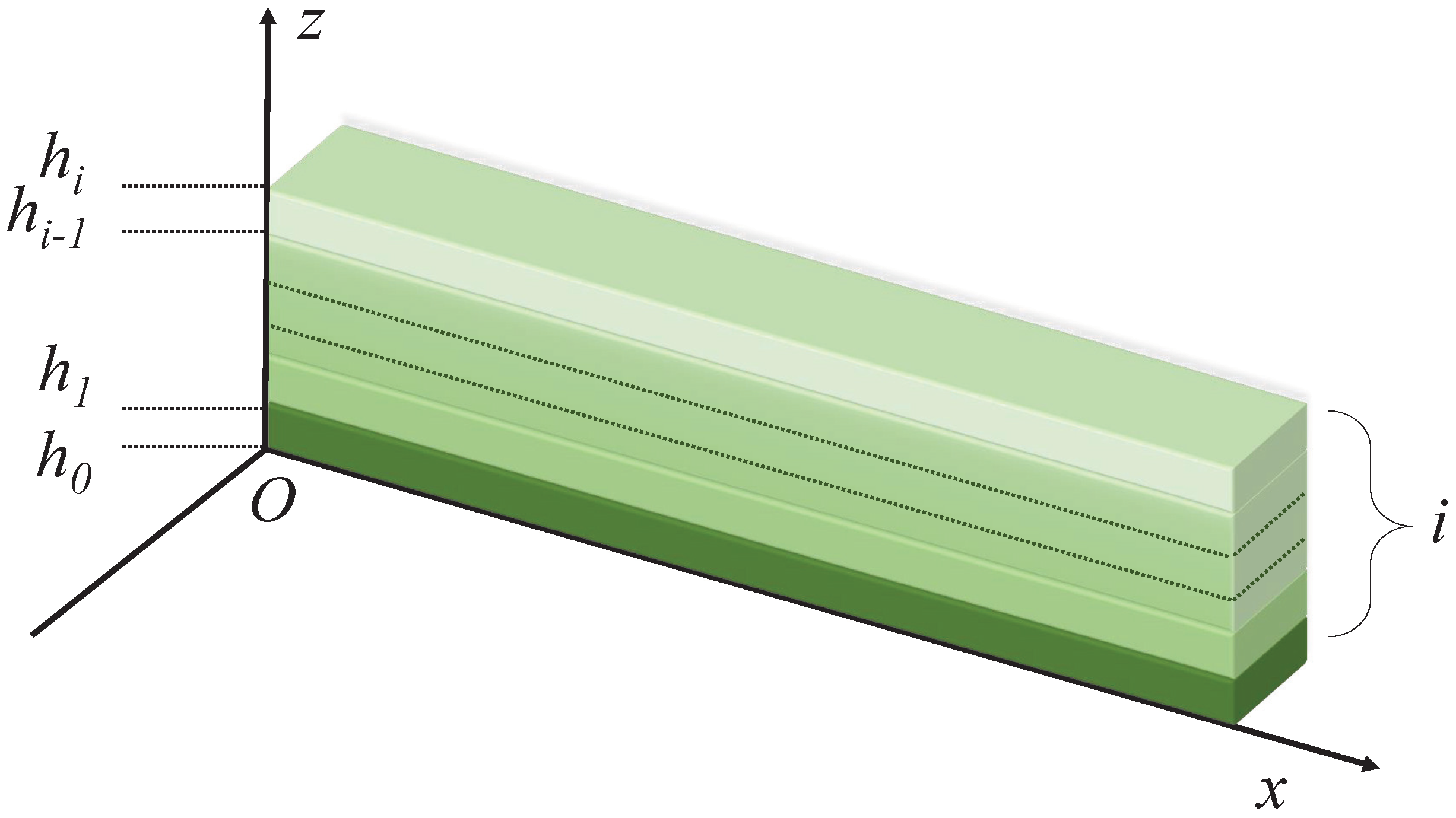
  • The bending vibration caused by the deformation in the y-direction is negligible. The fundamental equations of the piezoelectric materials can then be written as [15]
    s x = s 11 σ x + d 31 E 3 ,
    D 3 = d 31 σ x + ε 33 t E 3 ,
    where s x denotes the strain in the x-direction, s 11 is the compliance at a constant electric field, σ x is the stress in the x-direction, d 31 is the piezoelectric constant, E 3 is the electric field in the z-direction, D 3 is the electric displacement, and ε 33 t is the dielectric constant at a constant stress.
  • The MPCA vibrates with a small deflection. Then, the expression for s x is [15]
    s x = 2 u x 2 z .
  • Layers with no piezoelectric properties can be considered as piezoelectric layers with d 31 = 0 and ε 33 t = 0 .
Based on the above formulae, the steady-state displacement at x = l of an MPCA u ( l ) and the charge Q 3 passing through it can be deduced as follows:
u ( l ) = F k 3 P ( sinh k l cos k l sin k l cosh k l ) + R U w k 2 P sinh k l sin k l 1 + cosh k l cos k l ,
Q 3 = R k w R U w k 2 P ( sinh k l cos k l + sin k l cosh k l ) + F k 3 P sinh k l sin k l 1 + cosh k l cos k l + n = 1 i ( ε 33 n t d 31 n 2 s 11 n ) E n l w ,
where F denotes the force in the z-direction on an MPCA at x = l , ε 33 n t is the dielectric constant of the nth layer in the z-direction, d 31 n is the piezoelectric constant of the nth layer, and s 11 n is the compliance in the x-direction of the nth layer. Detailed derivations of Equations (4) and (5) are presented in Appendix A, where the expressions for k, P, Q, and R are also given.
According to Equations (4) and (5), the velocity of the MPCA v at x = l and the current I in the MPCA can be derived as follows:
v = j ω a v F F + j ω a v U U ,
I = j ω a v U F + j ω a i U U ,
with
a v F = 1 ω 3 / 2 P 1 / 4 Q 3 / 4 sinh k l cos k l sin k l cosh k l 1 + cosh k l cos k l ,
a v U = R w ω Q 1 / 2 P 1 / 2 sinh k l sin k l 1 + cosh k l cos k l ,
a i U = R 2 w 2 ω 1 / 2 P 3 / 4 Q 1 / 4 sinh k l cos k l + sin k l cosh k l 1 + cosh k l cos k l + n = 1 i ( ε 33 n t h n h n 1 d 31 n 2 s 11 n ( h n h n 1 ) ) l w .
Equations (6) and (7) describe the relationships among velocity, current, force, and voltage, which indicates the electromechanical conversion relationship in an MPCA.
Next, based on the analytical solutions of a single MPCA, the characteristics of multiple MPCA pairs in the piezoelectric cantilever MEMS loudspeaker can be deduced.
We denote the force exerted by a single MPCA on the middle coupling element as F 0 ( F 0 = F ) , the force exerted by all MPCAs on the middle coupling element as F t o t a l , and the total current passing through all MPCAs as I t o t a l . Assuming m pairs of MPCAs are connected to the middle coupling element, there is
F 0 = F t o t a l / 2 m , I = I t o t a l / 2 m .
Substituting Equation (11) into Equations (6) and (7) gives
F t o t a l = 2 m j ω a v F v + 2 m a v U a v F U ,
I t o t a l = 2 m a v U a v F v + j ω 2 m ( a i U a v U 2 a v F ) U .
Equations (12) and (13) clearly explain the electromechanical conversion relationship in the piezoelectric cantilever MEMS loudspeaker, which are the required expressions to establish a special transformer. The transformer of multiple pairs of MPCAs shown in Figure 3 is proposed to describe the coupling of the electrical and mechanical domains. It is suitable for all structures that use MPCAs in pairs. The built-in parameters of the transformer are as follows:
1 j ω C e = 1 j ω 2 m a i U j ω 2 m a v U 2 a v F ,
n = 2 m a v U a v F ,
1 j ω C m 0 = 2 m j ω a v F .

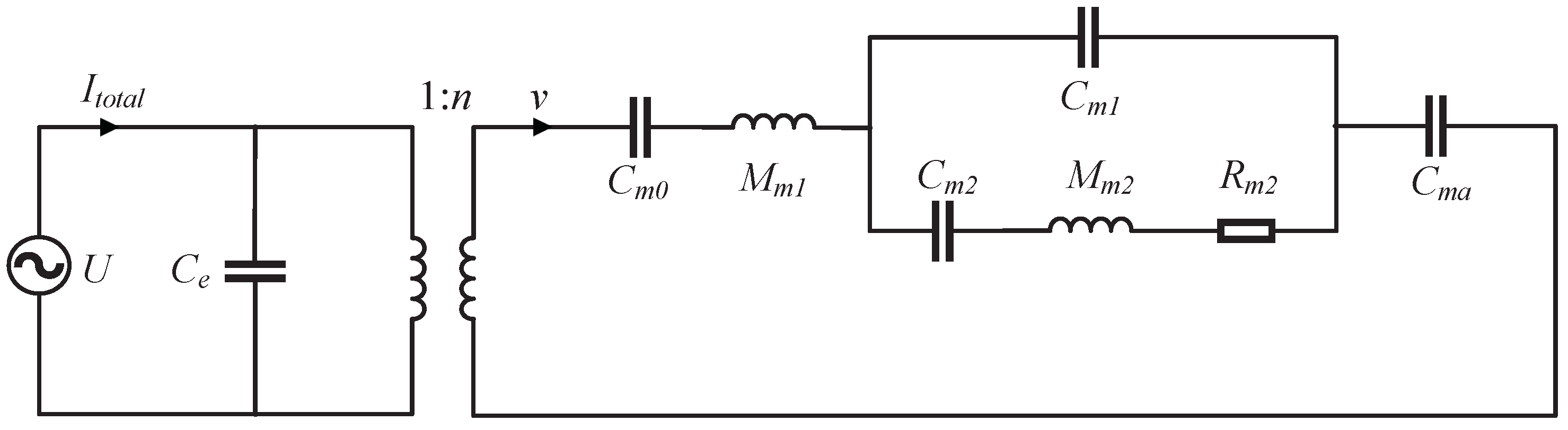
2.2. Equivalent Circuit of Piezoelectric Cantilever MEMS Loudspeaker

Figure 4 depicts the ECM model of the piezoelectric cantilever MEMS loudspeaker. In the mechanical domain, only the direction of vibration, i.e., the z-direction, needs to be considered. Therefore, the middle coupling element is modeled by a mass M m 1 and a mechanical compliance C m 1 in the z-direction:
C m 1 = h m Y S x y ,
where h m denotes the height of the middle coupling element in the direction of vibration, S x y is the cross-sectional area perpendicular to the direction of vibration, and Y is the Young’s modulus of the middle coupling element in the direction of vibration. The diaphragm is modeled by a mass M m 2 . The surround is modeled by a mechanical compliance C m 2 and a mechanical resistance R m 2 . The closed back cavity of the acoustic domain can be directly modeled by the compliance C m a in the mechanical domain, and is expressed as follows:
C m a = V ρ 0 c 2 S d 2 ,
where ρ 0 denotes the air density, c is the speed of sound in air, V is the volume of the closed back cavity, and S d is the area of the diaphragm.
According to the equivalent circuit depicted in Figure 4, the velocity of the diaphragm v p can be described as
v p = F p Z m = n U 1 j ω C m 0 + j ω M m 1 + 1 j ω C m 1 + 1 1 j ω C m 2 + j ω M m 2 + R m 2 + 1 j ω C m a ,
where F p denotes the total force acting on the mechanical domain and Z m is the total mechanical impedance. Then, the sound pressure p r in the half-space radiation environment of a piezoelectric cantilever MEMS loudspeaker can be calculated using the following equation:
p r = ω ρ 0 2 π r v p S d ,
where r denotes the distance between the loudspeaker and the measuring point. According to Equation (19), the displacement of the diaphragm can also be described.

3. Validation of ECM Using FEM Models and Discussions

To validate the effectiveness of the proposed ECM model, three different FEM models are built at varying levels of complexity using COMSOL Multiphysics®. Three elements are used to simulate piezoelectric cantilever MEMS loudspeakers: solid mechanics interface, electronics interface, and pressure acoustics interface. The solid mechanics interface includes diaphragm, surround, middle coupling element, and MPCAs. The electronics interface includes the piezoelectric part of the MPCAs. The pressure acoustics interface simulates the internal sound field, and the external sound field is described by the pressure acoustics, boundary elements interface. In order to describe the half-space radiation environment, the plane perpendicular to the vibration direction is set as infinite boundary condition. Coupling between different elements and the piezoelectric effect are all described by the Multiphysics branch. The mesh is small enough to ensure the accuracy of the simulation. The element number is 1020 in Case 1, 80,351 in Case 2, and 168,190 in Case 3.
The material selection in piezoelectric cantilever MEMS loudspeakers can be divided into two parts: MPCAs containing piezoelectric materials and other structures similar to the traditional miniature loudspeakers. For the MPCAs, referring to the typical materials of piezoelectric cantilevers for fabrication [16,17,18], a variety of different piezoelectric materials in the following three cases are selected in COMSOL material library for validation. For other structures, referring to the traditional miniature loudspeakers [19,20], common materials in practical applications are selected. The parameters in the three cases are given in the following tables.

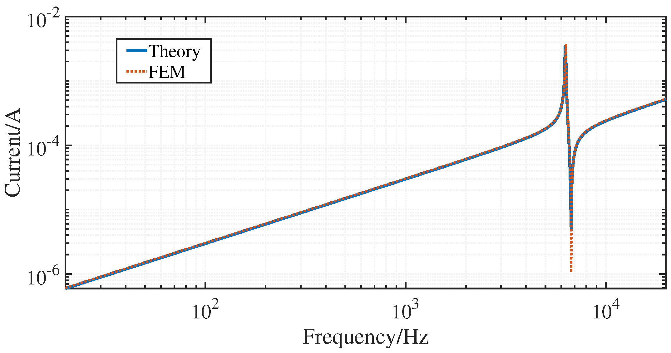
3.1. Case 1: A Single Four-Layer MPCA

An adequate transformer is required to establish the ECM model, and the validity of this transformer depends on the theoretical derivation of the MPCA. To verify the analytical solutions of the MPCA, this case adopts a model of a single four-layer MPCA, as shown in Figure 2. The conditions of an MPCA are mentioned in Section 2. The voltage in the z-direction is required, the MPCA is clamped on one end, and a force of 10 5 N / m 2 is applied on the other end. The other relevant parameters of each layer of the MPCA are listed in Table 1. The MPCA has four layers, two of which (layers 2 and 4, as indicated in Table 1) are piezoelectric materials.
The displacement and current characteristics are calculated based on Equations (4) and (5), respectively, and simulated based on the FEM model. As shown in Figure 5 and Figure 6, the theoretical and FEM results agree well in the range of 20 Hz to 20 kHz. A noticeable resonance is observed in the results of the displacement, which can be attributed to the lack of damping in the MPCA. The resonance frequency of the displacement is 6320 Hz in the FEM simulation and 6270 Hz in the ECM model. In the current results, the magnitude peak occurs at the same frequency as the displacement, and the frequency of the magnitude dip coincides in the two methods. An error of 0.79% indicates that these methods achieve satisfactory agreement.

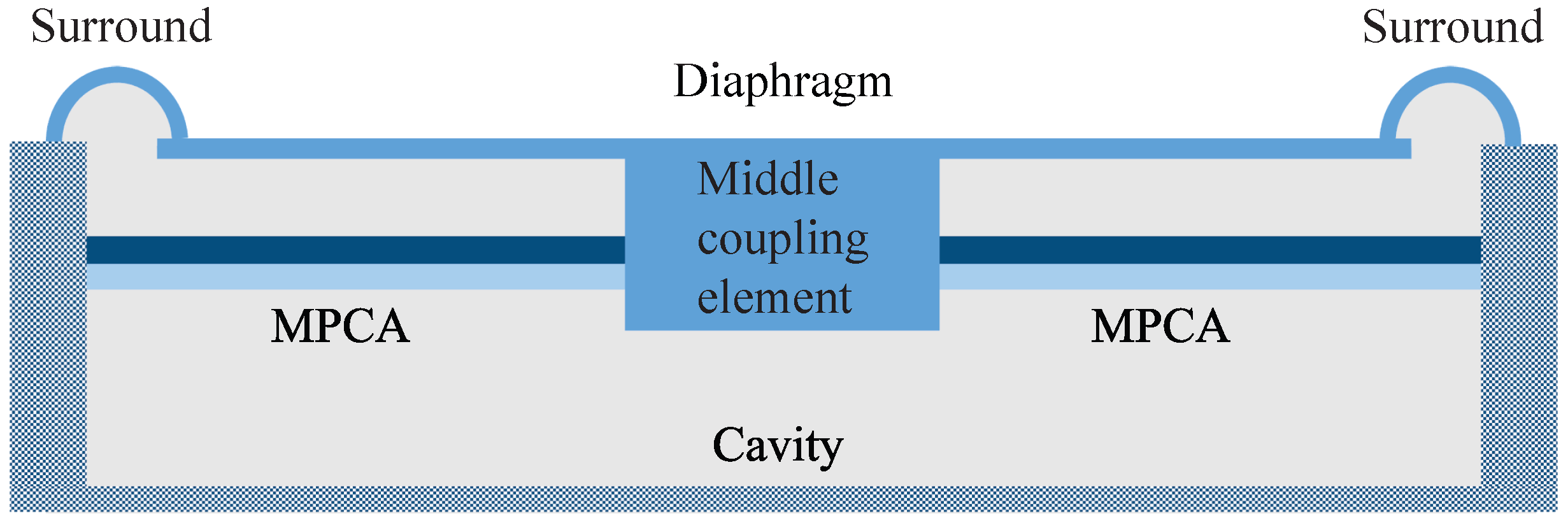
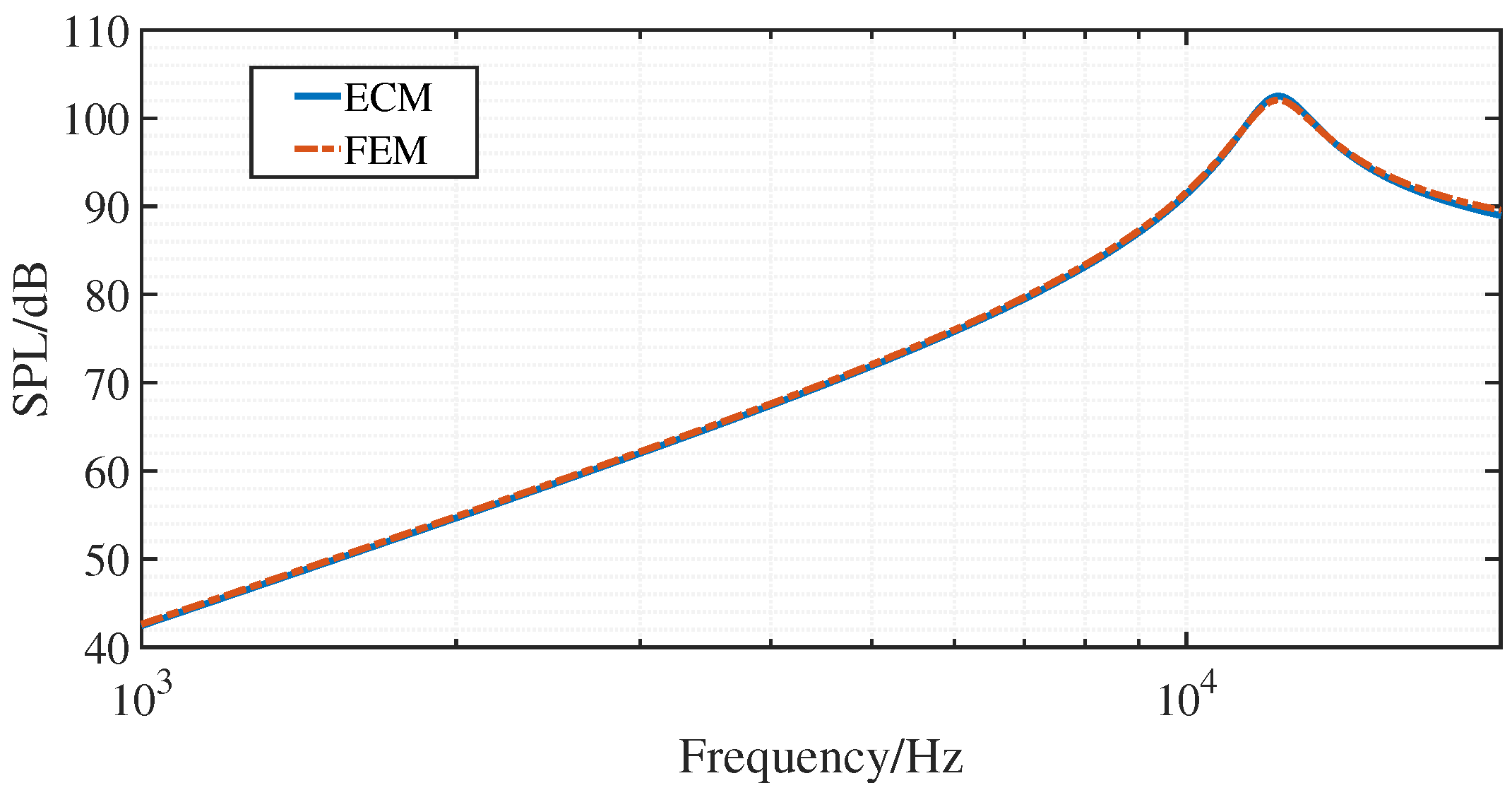
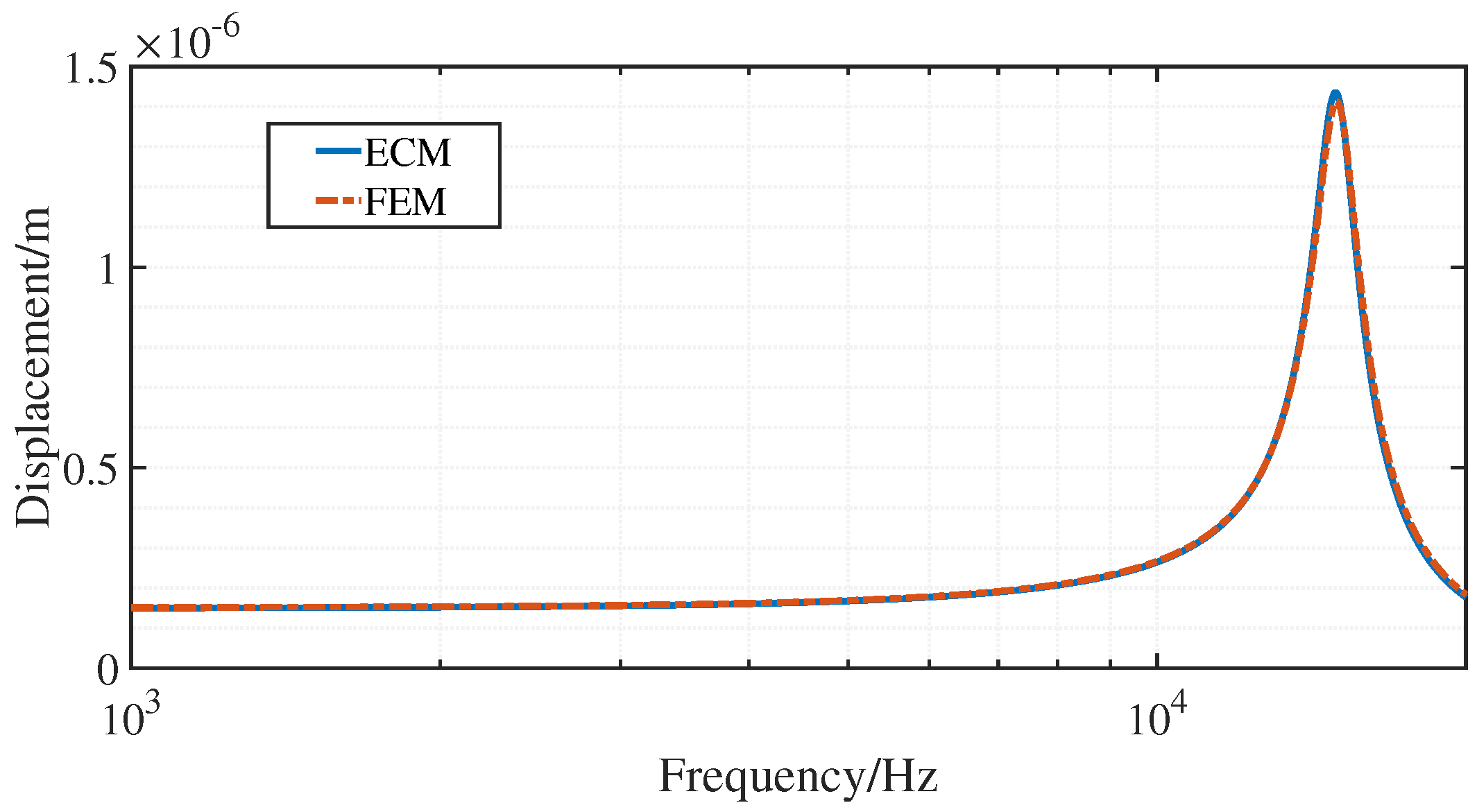
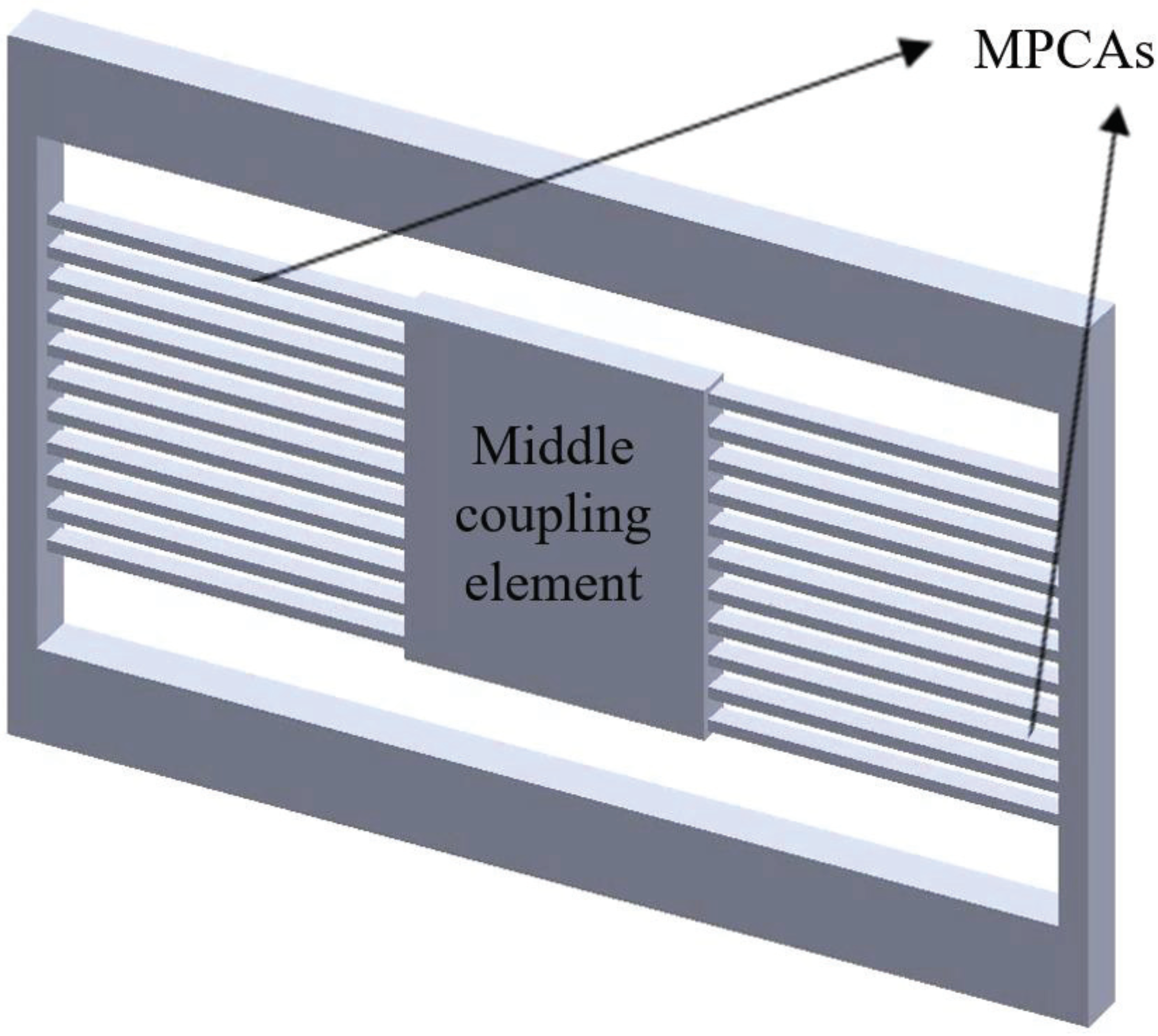
3.2. Case 2: A Piezoelectric Cantilever MEMS Loudspeaker with a Two-Sided Structure

Figure 7 depicts the two-sided structure used in the models of the piezoelectric cantilever MEMS loudspeaker. In this case, there are 17 pairs of two-layer MPCAs distributed symmetrically on both sides of the middle coupling element. Table 2 lists the parameters of the two-layer MPCAs for this case, and Table 3 lists the parameters of the ECM model.
The displacement is calculated according to Equation (19), and the sound pressure response is calculated based on Equation (20). Comparison of the results of the displacement and sound pressure responses are shown in Figure 8 and Figure 9, respectively. The good agreement between these results indicates the accuracy of the ECM model. The resonance frequency is 12,100 Hz in the FEM simulation and 12,150 Hz in the ECM model. An error of 0.41% indicates satisfactory agreement between these methods. In the resonance domain, there is a slight deviation between the two methods because of the differences in the damping settings.

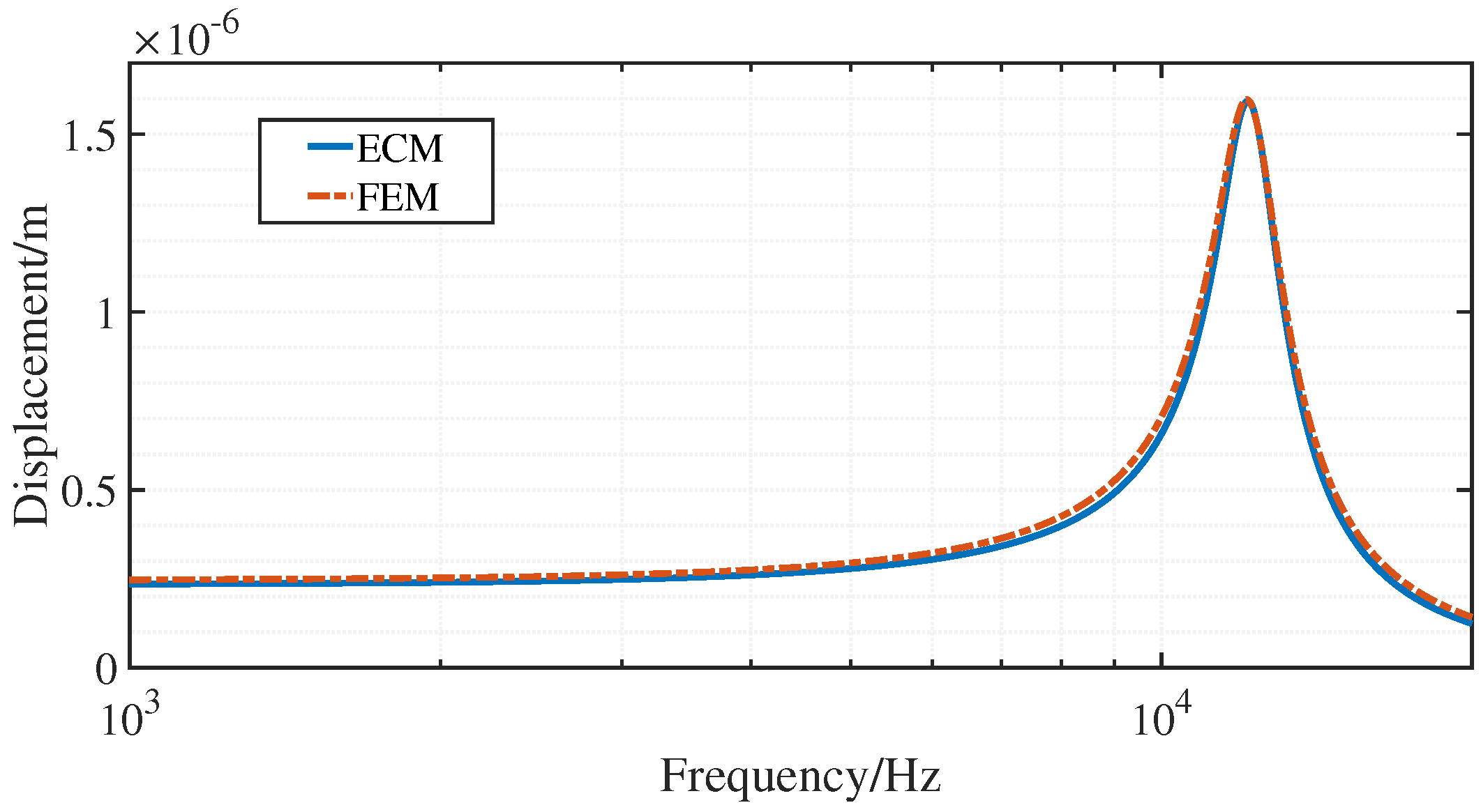
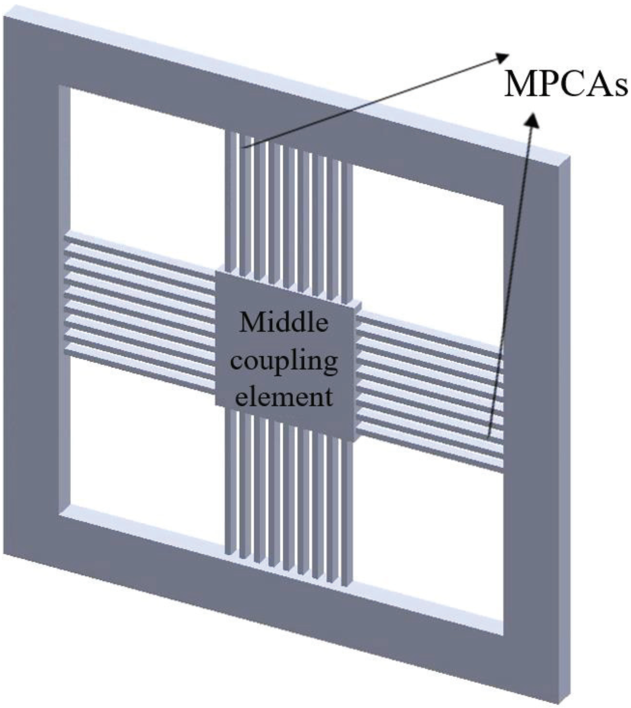
3.3. Case 3: A Piezoelectric Cantilever MEMS Loudspeaker with a Four-Sided Structure

The four-sided structure used in the piezoelectric cantilever MEMS loudspeaker is shown in Figure 10. In this case, there are 26 pairs of three-layer MPCAs distributed on four sides of the middle coupling element. The four-sided structure is more complex than the two-sided structure, but the transformer is expected to work in both cases according to the assumptions and derivation presented in Section 2. The relevant parameters are listed in Table 4 and Table 5.
Figure 11 and Figure 12 depict the results of the displacement and sound pressure responses, respectively. The FEM and ECM models exhibit a resonance frequency of 15,000 and 14,950 Hz, respectively, and the error is 0.33%. Although reasonable differences between the resonance domains of the two methods remain, overall, there is good agreement between the results.

4. Conclusions

A transformer suitable for pairs of MPCAs was proposed by deducing the motion and current of MPCAs. Based on the proposed transformer, an analytical model using the ECM was established to describe the piezoelectric cantilever MEMS loudspeaker. To verify the proposed model, FEM simulations were performed at three different complexity levels, and the results were compared with those of the ECM model. The satisfactory agreement achieved between the results of the two methods indicates that the ECM model developed in this work is an effective tool for analyzing the performances of piezoelectric cantilever MEMS loudspeakers.
Therefore, the use of ECM models with a special transformer is an efficient method for modeling piezoelectric cantilever MEMS loudspeakers. The analytical ECM model fundamentally reveals the relationship between the parameters and performances of piezoelectric cantilever MEMS loudspeakers. This general model is numerically fast to compute, which makes the analysis process more convenient. Based on the proposed ECM model, the parametric analysis and optimization of piezoelectric cantilever MEMS loudspeakers may be investigated in future studies.

Author Contributions

Conceptualization, W.L. and Y.S.; methodology, W.L.; validation, W.L.; formal analysis, W.L.; investigation, W.L. and J.C.; writing—original draft preparation, W.L.; writing—review and editing, W.L. and J.H.; supervision, project administration, funding acquisition, Y.S. All authors have read and agreed to the published version of the manuscript.

Funding

This research received no external funding.

Institutional Review Board Statement

Not applicable.

Informed Consent Statement

Not applicable.

Data Availability Statement

Not applicable.

Acknowledgments

The authors would like to thank Hao Dong and Xuelei Feng who made suggestions for this study.

Conflicts of Interest

The authors declare no conflict of interest.

Abbreviations

The following abbreviations are used in this manuscript:
MEMSmicroelectromechanical system
MPCAmultilayer piezoelectric cantilever actuator
ECMequivalent circuit method
FEMfinite element method

Appendix A

Generally, a plane z = t 0 with zero stress is selected when no voltage is applied, and the displacement of this plane is regarded as the total displacement of the MPCA:
n = 1 i h n 1 h n 1 s 11 n 2 u x 2 ( z t 0 ) d z = 0 ,
t 0 = n = 1 i h n 2 h n 1 2 2 s 11 n n = 1 i h n h n 1 s 11 n .
Upon applying a voltage U in the z-direction on an MPCA, the bending moment M x of the cross-section at x relative to the z = t 0 plane is
M x = σ x w z d z .
According to Equations (1) and (3),
M x = n = 1 i w h n t 0 3 h n 1 t 0 3 3 s 11 n 2 u x 2 + n = 1 i d 31 n w 2 s 11 n h n t 0 2 h n 1 t 0 2 E n ,
where E n = U / h n h n 1 . The shear force F z and bending moment M x satisfy
F z d x + d M x = 0 .
Substituting Equation (A4) into (A5) yields
F z = d M x d x = n = 1 i w h n t 0 3 h n 1 t 0 3 3 s 11 n 3 u x 3 .
According to Newton’s second law, the equation of motion is
d F z d x d x = n = 1 i ρ n w h n h n 1 2 u t 2 d x ,
where ρ n denotes the density of the nth layer. Owing to the harmonic vibration of the MPCA, it follows that
u = u x e j ω t .
Substituting Equations (A6) and (A8) into Equation (A7) yields
P 4 u ( x ) x 4 Q ω 2 u ( x ) = 0 ,
with
P = n = 1 i w [ ( h n t 0 ) 3 ( h n 1 t 0 ) 3 ] 3 s 11 n ,
Q = n = 1 i ρ n w ( h n h n 1 ) ,
R = n = 1 i d 31 n 2 s 11 n ( h n + h n 1 2 t 0 ) .
A general solution for Equation (A9) is
u ( x ) = A cosh k x + B sinh k x + C cos k x + D sin k x ,
where k = ω P / Q . In piezoelectric cantilever MEMS loudspeakers, the MPCA is clamped at x = 0 and connected to a middle coupling element at x = l . Therefore, the boundary conditions can be expressed as
u 0 = 0 , u ( x ) x x = 0 = 0 ,
F z x = l = F , M x x = l = 0 ,
Then, the coefficients are calculated as follows:
A = F k 3 P ( sinh k l + sin k l ) + R U w k 2 P ( cosh k l + cos k l ) 2 2 cosh k l cos k l ,
B = F k 3 P ( cosh k l + cos k l ) R U w k 2 P ( sinh k l + sin k l ) 2 2 cosh k l cos k l ,
C = A , D = B .
Then, the steady-state displacement at x = l can be deduced.
According to Equations (1)–(3), the electric displacement through a piezoelectric layer is
D 3 = d 31 2 u x 2 ( z t 0 ) s 11 p + ( ε 33 t d 31 2 s 11 ) E 3 .
The mean electric displacement of an MPCA is
D 3 ¯ = n = 1 i h n 1 h n D 3 d z h n h n 1 = n = 1 i [ d 31 n 2 s 11 n ( h n + h n 1 2 t 0 ) 2 u x 2 + ( ε 33 n t d 31 n 2 s 11 n ) E 3 ] .
The charge passing through the beam Q 3 is [21,22]
Q 3 = 0 w d y 0 l D 3 ¯ d x .
Substituting Equation (A20) into (A21) yields Equation (5).

References

  1. Männchen, A.; Stoppel, F.; Beer, D.; Niekiel, F.; Wagner, B. In-ear headphone system with piezoelectric mems driver. In Proceedings of the 145th AES Convention, New York, NY, USA, 17–20 October 2018. [Google Scholar]
  2. Je, S.S.; Rivas, F.; Diaz, R.E.; Kwon, J.; Kim, J.; Bakkaloglu, B.; Kiaei, S.; Chae, J. A compact and low-cost MEMS loudspeaker for digital hearing aids. IEEE Trans. Biomed. Circuits. Syst. 2009, 3, 348–358. [Google Scholar] [CrossRef] [PubMed]
  3. Shahosseini, I.; Lefeuvre, E.; Moulin, J.; Woytasik, M.; Martincic, E.; Pillonnet, G.; Lemarquand, G. Electromagnetic MEMS microspeaker for portable electronic devices. Microsyst. Technol. 2013, 19, 879–886. [Google Scholar] [CrossRef] [Green Version]
  4. Garud, M.; Godthi, V.; Reddy, J.; Dangi, A.; Pratap, R. Cricket inspired high efficiency MEMS speakers. In Proceedings of the Multidisciplinary Digital Publishing Institute, Paris, France, 3–6 September 2017; Volume 1, p. 345. [Google Scholar]
  5. Albach, T.S.; Lerch, R. Magnetostrictive microelectromechanical loudspeaker. J. Acoust. Soc. Am. 2013, 134, 4372–4380. [Google Scholar] [CrossRef] [PubMed]
  6. Cho, I.J.; Jang, S.; Nam, H.J. A piezoelectrically actuated mems speaker with polyimide membrane and thin film pb (zr, ti) o3 (pzt) actuator. Integr. Ferroelectr. 2009, 105, 27–36. [Google Scholar] [CrossRef]
  7. Dejaeger, R.; Casset, F.; Desloges, B.; Le Rhun, G.; Robert, P.; Fanget, S.; Leclère, Q.; Ege, K.; Guyader, J.L. Development and characterization of a piezoelectrically actuated MEMS digital loudspeaker. Procedia Eng. 2012, 47, 184–187. [Google Scholar] [CrossRef]
  8. Ko, S.C.; Kim, Y.C.; Lee, S.S.; Choi, S.H.; Kim, S.R. Micromachined piezoelectric membrane acoustic device. Sens. Actuator A Phys. 2003, 103, 130–134. [Google Scholar] [CrossRef]
  9. Cho, K.; Yi, S.; Son, Y.; Kweon, S. Characteristics of piezoelectric micro-speaker fabricated with ZnO thin film. Integr. Ferroelectr. 2007, 89, 141–149. [Google Scholar] [CrossRef]
  10. Stoppel, F.; Niekiel, F.; Giese, T.; Gu-Stoppel, S.; Männchen, A.; Nowak, J.; Beer, D.; Wagner, B. Novel type of MEMS loudspeaker featuring membrane-less two-way sound generation. In Proceedings of the 143rd AES Convention, New York, NY, USA, 18–21 October 2017. [Google Scholar]
  11. Cheng, H.H.; Lo, S.C.; Huang, Z.R.; Wang, Y.J.; Wu, M.; Fang, W. On the design of piezoelectric MEMS microspeaker for the sound pressure level enhancement. Sens. Actuator A Phys. 2020, 306, 111960. [Google Scholar] [CrossRef]
  12. Liechti, R.; Durand, S.; Hilt, T.; Casset, F.; Dieppedale, C.; Verdot, T.; Colin, M. A Piezoelectric MEMS Loudspeaker Lumped and FEM models. In Proceedings of the 2021 22nd International Conference on Thermal, Mechanical and Multi-Physics Simulation and Experiments in Microelectronics and Microsystems (EuroSimE), Virtual, 19–22 April 2021; pp. 1–8. [Google Scholar]
  13. Wang, H.; Chen, Z.; Xie, H. A high-SPL piezoelectric MEMS loud speaker based on thin ceramic PZT. Sens. Actuator A Phys. 2020, 309, 112018. [Google Scholar] [CrossRef]
  14. Beltrami, A.R.C.; Bottoni, F. MEMS Circuit Board Module Having an Integrated Piezoelectric Structure, and Electroacoustic Transducer Arrangement. U.S. Patent 10,433,063, 1 October 2019. [Google Scholar]
  15. Lin, S. Principle and Design of Ultrasonic Transducer, 1st ed.; Science Press: Beijing, China, 2004. [Google Scholar]
  16. Song, R.; Shan, X.; Lv, F.; Xie, T. A study of vortex-induced energy harvesting from water using PZT piezoelectric cantilever with cylindrical extension. Ceram. Int. 2015, 41, S768–S773. [Google Scholar] [CrossRef]
  17. Shen, D.; Park, J.H.; Noh, J.H.; Choe, S.Y.; Kim, S.H.; Wikle, H.C., III; Kim, D.J. Micromachined PZT cantilever based on SOI structure for low frequency vibration energy harvesting. Sens. Actuator A Phys. 2009, 154, 103–108. [Google Scholar] [CrossRef]
  18. Shen, D.; Park, J.H.; Ajitsaria, J.; Choe, S.Y.; Wikle, H.C.; Kim, D.J. The design, fabrication and evaluation of a MEMS PZT cantilever with an integrated Si proof mass for vibration energy harvesting. J. Micromech. Microeng. 2008, 18, 055017. [Google Scholar] [CrossRef]
  19. Huang, J.H.; Her, H.C.; Shiah, Y.; Shin, S.J. Electroacoustic simulation and experiment on a miniature loudspeaker for cellular phones. J. Appl. Phys. 2008, 103, 033502. [Google Scholar] [CrossRef]
  20. Lee, C.M.; Kwon, J.H.; Hwang, S.M. Analysis of total harmonic distortion in microspeakers considering coupling effect. J. Mech. Sci. Technol. 2010, 24, 1763–1769. [Google Scholar] [CrossRef]
  21. Smits, J.G.; Ballato, A. Dynamic admittance matrix of piezoelectric cantilever bimorphs. J. Microelectromech. Syst. 1994, 3, 105–112. [Google Scholar] [CrossRef]
  22. Okugawa, M.; Sasaki, M. System identification and controller design of a self-sensing piezoelectric cantilever structure. J. Intell. Mater. Syst. Struct. 2002, 13, 241–252. [Google Scholar] [CrossRef]
Figure 1. Schematic of a piezoelectric cantilever MEMS loudspeaker.
Applsci 11 06323 g001
Figure 2. Schematic of a multilayer piezoelectric cantilever actuator (MPCA).
Applsci 11 06323 g002
Figure 3. Transformer for multiple pairs of MPCAs.
Applsci 11 06323 g003
Figure 4. Equivalent circuit of a piezoelectric cantilever MEMS loudspeaker.
Applsci 11 06323 g004
Figure 5. Results of the displacement of the single MPCA.
Applsci 11 06323 g005
Figure 6. Results of the current of the single MPCA.
Applsci 11 06323 g006
Figure 7. Schematic of the two-sided structure.
Applsci 11 06323 g007
Figure 8. Results of the sound pressure response in Case 2.
Applsci 11 06323 g008
Figure 9. Results of the displacement in Case 2.
Applsci 11 06323 g009
Figure 10. Schematic of the four-sided structure.
Applsci 11 06323 g010
Figure 11. Results of the sound pressure response in Case 3.
Applsci 11 06323 g011
Figure 12. Results of the displacement in Case 3.
Applsci 11 06323 g012
Table 1. Parameters of the single MPCA.
Layer 1Layer 2Layer 3Layer 4
l / m m 5.005.005.005.00
w / m m 0.150.150.150.15
h n / m m 0.100.110.130.14
h n 1 / m m 00.100.110.13
ρ n / k g   m 3 2329750023291780
s 11 n / Pa 1 5.88 × 10 12 1.65 × 10 11 5.88 × 10 12 3.78 × 10 10
d 31 n / C   N 1 0 2.74 × 10 10 0 1.36 × 10 11
ε 33 n T ε 0 1 /-0340007.74
U / V 02.1202.12
Table 2. Parameters of the MPCAs in Case 2.
MPCALayer 1Layer 2
l / m m 3.003.00
w / m m 0.100.10
h n / m m 0.180.2
h n 1 / m m 00.18
ρ n / k g   m 3 23297500
s 11 n / Pa 1 5.88 × 10 12 1.65 × 10 11
d 31 n / C   N 1 0 2.74 × 10 10
ε 33 n T ε 0 1 /-03400
U / V 05.66
Table 3. Parameters of the ECM model in Case 2.
Parameter M m 1 / kg C m 1 / m   N 1 S d / m 2 M m 2 / kg
4.50 × 10 6 1.05 × 10 6 1.48 × 10 5 5.40 × 10 6
Parameter C m 2 / m   N 1 R m 2 / s   N   m 1 C m a / m   N 1 -
3.34 × 10 5 0.122 9.91 × 10 4 -
Table 4. Parameters of the MPCAs in Case 3.
MPCALayer 1Layer 2Layer 3
l / m m 2.802.802.80
w / m m 0.080.080.08
h n / m m 0.150.1550.16
h n 1 / m m 00.150.155
ρ n / k g   m 3 232975007600
s 11 n / Pa 1 5.88 × 10 12 1.23 × 10 11 1.16 × 10 11
d 31 n / C   N 1 0 1.23 × 10 10 6.00 × 10 11
ε 33 n T ε 0 1 /-01300450
U / V 03.543.54
Table 5. Parameters of the ECM model in Case 3.
Parameter M m 1 / kg C m 1 / m   N 1 S d / m 2 M m 2 / kg
1.44 × 10 6 5.81 × 10 8 1.53 × 10 5 4.32 × 10 6
Parameter C m 2 / m   N 1 R m 2 / s   N   m 1 C m a / m   N 1 -
3.30 × 10 5 0.066 1.10 × 10 3 -
Publisher’s Note: MDPI stays neutral with regard to jurisdictional claims in published maps and institutional affiliations.

