1. Introduction
Among small-scale transducers, piezoelectric ceramics can achieve exceptionally high work and power densities [
1]. They can operate with comparatively simple geometry, and consume lower currents and reach higher bandwidths than shape memory alloy or electrothermal transducers. Their combination of high force generation, fast response time, and modest power consumption has made piezoelectric actuators promising for small-scaled robotics. For example, piezoelectric actuation has been used in miniature walking robots [
2,
3,
4,
5] and in anthropomorphic robotic hands [
6]. However, when it becomes necessary to generate large displacement amplitudes, piezoelectric actuators are rarely ideal due to low intrinsic strain. While operation at resonance can amplify motion substantially, it is also difficult to design piezoelectric ceramics to produce resonance in low frequency ranges, especially at small size scales [
7]. This can result in a mismatch between the highest-amplitude operating frequencies of a piezoelectric actuator and those of the natural dynamics of a small robotic system, when seeking to produce naturalistic walking or swimming gaits.
To address the above shortcomings, many researchers have used amplification mechanisms to increase piezoelectric actuator stroke. For example, a compact out-of-plane architecture used a half-scissor mechanism to convert the small in-plane elongation of a piezoceramic into a much larger out-of-plane displacement [
8]. Flextensional microactuators consist of a bulk piezoelectric material bonded to endcaps that flexes in response to piezoelectric contraction [
9]. Thus, the small piezoelectric contraction is amplified through buckling of the flextensional structure. Significant amplification can also be achieved via a combination of a chevron bridge and lever arms [
10], though requiring a much-increased total footprint. Drawbacks of these schemes are that substantial actuator work must be expended to deform the elastic actuation structures, and dynamic amplification tends to remain most effective at high frequency ranges for electromechanical impedance matching between the transducer and mechanism.
Alternatively, piezoelectric actuation has been used to produce large or even continuous output displacements through contact interactions [
11]. Piezoelectric wiggle motors are among the world’s smallest linear motors, using ultrasonic standing wave vibrations to directly rotate a screw [
12]. Various other piezoelectric motors designs, based variously on impact events, traveling waves, or stick–slip behavior, have been developed to drive a free rotor or body [
13,
14,
15,
16]. This permits large displacement or even continuous-displacement outputs, but tends to require complex fabrication and provide small load-bearing capacity. Impact dynamics have also been used in energy harvesting to couple piezoelectric transducers to vibration sources in widely disparate frequency domains [
17,
18].
Here, we explore a concept for dynamic amplification of a piezoelectric transducer via impact interaction with a compliant structure. Conceptually, the opportunity is to build kinematic energy within the piezoelectric ceramic and transfer it to deformation of the elastic output mechanism at impact. This is similar to the operating principle of linear impact-based actuators [
19,
20], sometimes driven piezoelectrically. However, in the proposed scheme, there is a permanent elastic connection between elements to permit simple assembly, and frequency differences are used to let the active element return to its full resonant amplitude between impacts. This contrasts with the use of individual accelerations of the transducer to induce each impact. With proper frequency selection, in the proposed scheme, impact periods can settle into quasi-periodic patterns, including examples with down-conversion in frequency by a factor of 10 or more. The potential advantages of piezoelectric amplification by this method include comparatively simple mechanism geometry, large amplification at low output frequencies, and reasonable efficiency despite energy losses during impact events. Limitations include high sensitivity to static loading and dependence on multiple degree-of-freedom compliance that can make packaging challenging within a small robotic system.
In this paper, we begin by introducing an impact amplification concept and simple dynamic model illustrating potential amplification scenarios. We then describe an experimental system and show examples of large dynamic amplification. Finally, we revisit some of the strengths and weaknesses of the mechanism, including early experiments for coupling in a small robotic testbed.
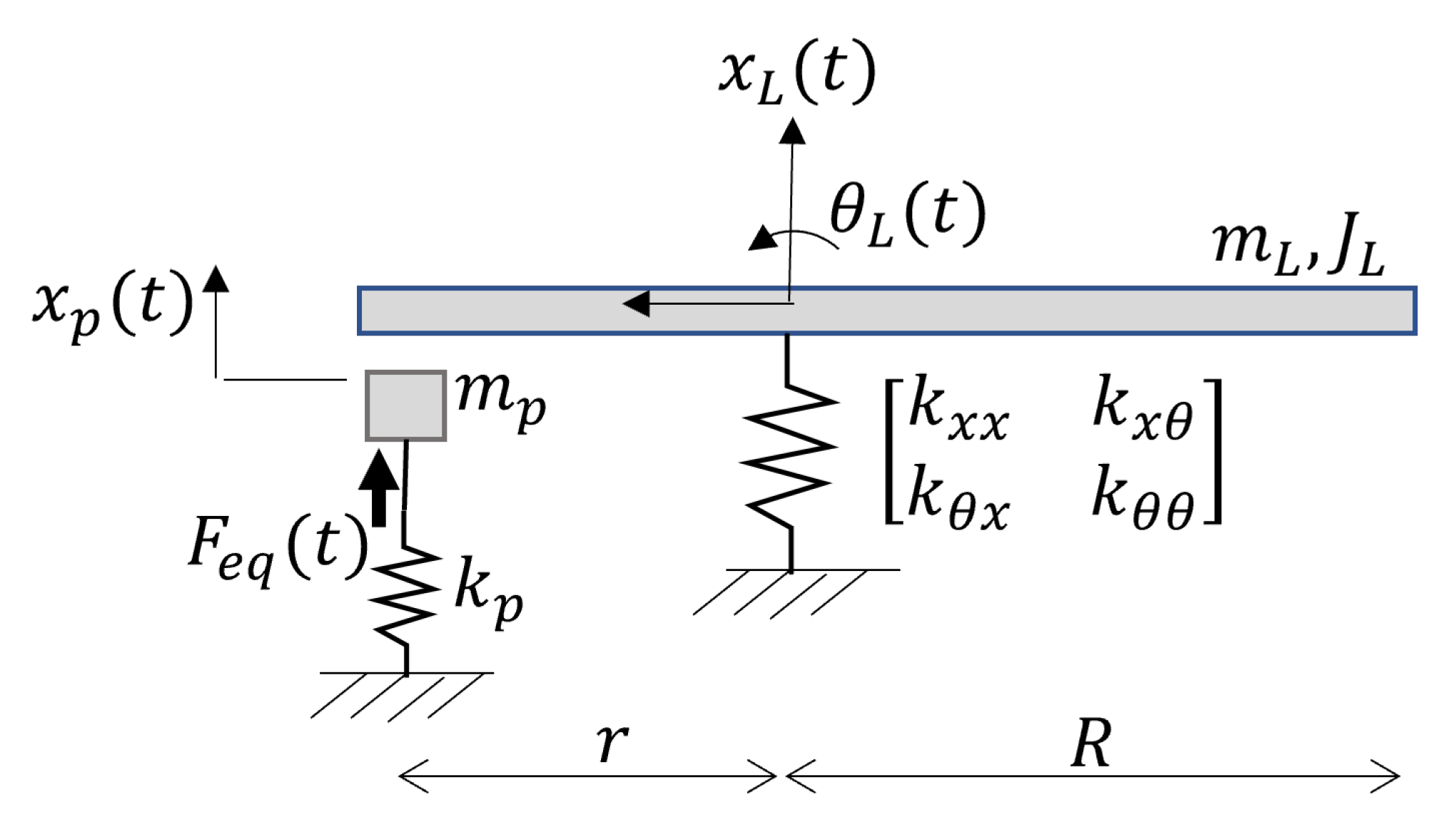
2. Conceptual Model
To introduce the proposed amplification mechanism, consider a simple transducer model, represented by an actuated point mass, impacting a rigid beam supported by a multi-axis spring, shown schematically in
Figure 1. All reference displacements are measured from their nominal rest position under gravity. The dynamics of the point mass represent an idealized mass-spring-damper approximation of a piezoelectric transducer,
where
is the displacement of the tip of the piezoelectric element (i.e., a piezoelectric bender or stack),
represents its effective mass,
is its effective stiffness and
is a damping constant.
represents the input forcing generated by the piezoelectric material as a function of time,
t, which depends on an applied voltage,
V, one or more piezoelectric coefficients,
, and the geometry of the element. For example, for a piezoelectric bimorph bender, shown schematically in
Figure 2, input force may be approximated from the blocking force for the bender as a function of voltage, or
where electromechanical coupling is primarily through the
piezoelectric constant,
,
, and
are the thickness, width, and length of the piezoelectric layers,
is the elastic modulus of the piezoelectric layer, and
is the distance from the midline of each piezoelectric layer to the neutral axis of the bender (assuming opposite polarities for the top and bottom piezoelectric layers).
The piezoelectric element interacts with a compliant structure capable of elastic deformation in translation,
, and rotation,
, with dynamics:
where
and
are the equivalent mass and rotational inertia of the mechanism,
and
are damping constants in each axis, and
and
are spring constants between translational force and translational displacement, respectively, and
and
are stiffness matrix cross-axis terms. During simulation, the output mechanisms is treated as being under negligible external load except during impact, which is modeled by discrete changes in velocity states.
Impact is assumed to occur whenever the piezoelectric actuator displacement would pass below the underlying load beam, taken to be a distance
r from the compliant spring connection with nominal gap
d (i.e., impact occurs if
). For a very simple model of impact, the two structures are taken to be approximated by interaction according to a simple coefficient of restitution (CoR) model while obeying conservation of linear and angular momentum, or
where superscripts ‘+’ and ‘−’ denote state velocities after and before impact, respectively. Equation (
4) is the CoR relationship, (5) the linear momentum balance, and (6) the angular momentum balance, measured in reference to the output spring location.
This represents a very simplistic approximation of impact behavior between two compliant structures, neglecting factors such as modal vibration effects, adhesion or other nonlinear interfacial forces, and the sensitivity of CoR to angle and location of impact. Nonetheless, the model in (
1)–(
6) will be seen to predict certain characteristic behaviors later observed in experimental testing.
Motion output is measured at the far tip of the passive beam, a distance
R from the compliant spring connection, with vertical output displacement,
approximated for small angles by
To illustrate the behavior of this class of the interacting components, the model in (1)–(7) was simulated numerically under square wave inputs with varying frequency, using parameters listed in
Table 1. Output behavior is characterized from time domain results and dominant frequency components of the resulting motion after achieving quasi-steady-state oscillation, as shown in
Figure 3.
Notably, the simulated output oscillations do not occur at the input frequency, even when the PZT bender is driven near resonance. Rather, output oscillations are produced in the frequency range of amplification mechanism dynamics, but with tunability between dominant frequencies by input.
Figure 4 shows sample simulation trajectories at 3.7 Hz, 75 Hz, and 225 Hz (bender resonance), with gradually increasing frequency and amplitude of quasi-periodic output oscillations. Trends are shown more comprehensively across input frequencies in an output displacement spectrum, shown in
Figure 5, with input excitation frequencies generating substantial output amplitudes at various frequencies between 1 and 250 Hz, and corresponding output frequencies rising from about 2.5 to 6.5 Hz. These oscillations occur between the natural frequencies of the compliant system in (3) alone (2.3 Hz and 10.5 Hz), with both rotational and translational deformation present. Highest amplitudes are achieved when the differing response times of those axes complement each other as measured at the mechanism output. However, while the frequencies at which this occurs are dependent on input frequency, in simulation, the uniformity of motion tends to become worse as input frequency is increased.
Overall, the basic arrangement of a high-frequency oscillator impacting a compliant structure produces extremely large amplification ratios between piezoelectric bender displacement and output displacement. These can be as high as 60:1 when the bender is driven substantially below resonance. In addition, a variety of input–output frequency ratios are possible, either for tuning the output frequency or minimizing energy consumption.
In the next section, we examine whether these types of behavior can be achieved in a physical setting, with characterization of an experimental prototype with dimensions near that of the simulated design.
Experimental Setup
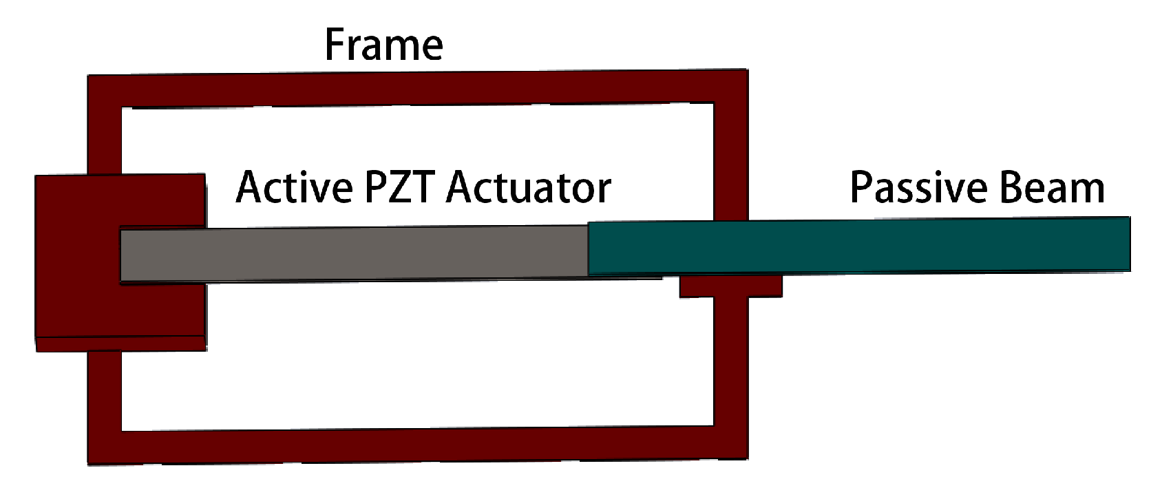
A prototype amplification mechanism was constructed that consists of a lead–zirconate–titanate (PZT), brass-reinforced bimorph bender (Mide Technology, T220-series), a 3D-printed compliant amplification structure, and a passive rigid beam. A schematic view of the amplification structure is shown in
Figure 6, while
Figure 7 shows an illustrative photograph of the system. The compliant amplification structure was designed as two thin beams parallel to the active bender with a torsion bar connection on which to mount the passive output beam, providing both translational and rotational compliance. The rigid element, in this case a second, un-actuated PZT beam, is used as the impact point to ensure a high CoR between active and passive components. The assembly’s total size is 55 mm × 22 mm × 1 mm.
The compliant mechanism was fabricated from polylactic acid (PLA), printed with an extrusion-based 3D printer (Comgrow Creativity Ender 3). Epoxy was used to mount the active bender and compliant frame to an anchor, and to attach the passive output beam to the torsion link of the compliant structure.
The prototype was excited by sine and square wave excitation from 0 to 1000 Hz using a function generator. Input signal was amplified to 40 V driving amplitude by an amplifier (TEGAM, Model 2350). Motion was measured using a vertical displacement profiler (Keyence, LJ-V7001P) with sampling rate up to 6.4 kHz. The behavior of motion was calculated from the height of the central point of either the active bender or passive output beam when measured in profile as a function of time. The motion amplitude and dominant frequency were extracted from the fast Fourier transform (FFT) of resulting time-series measurements.
3. Results
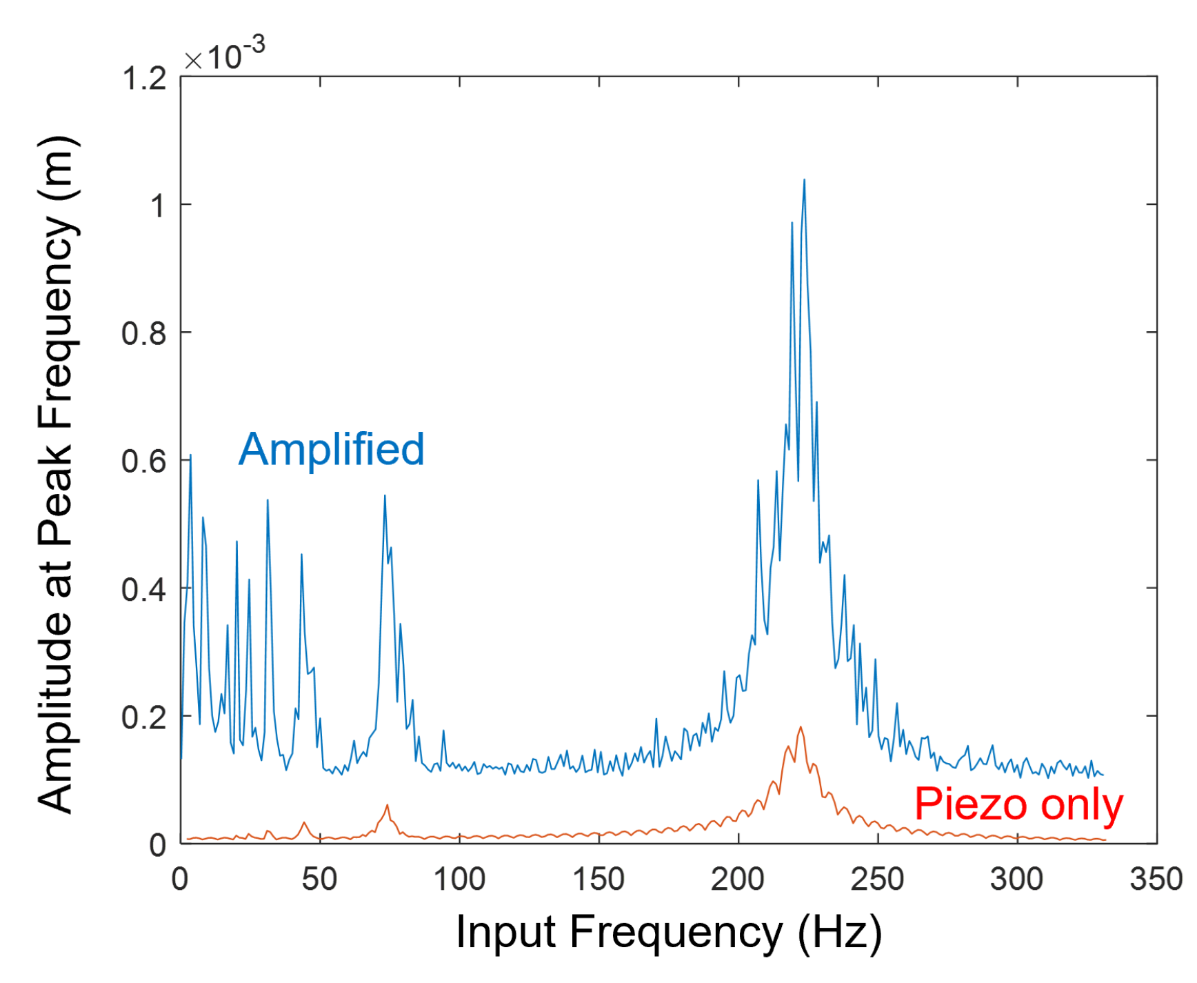
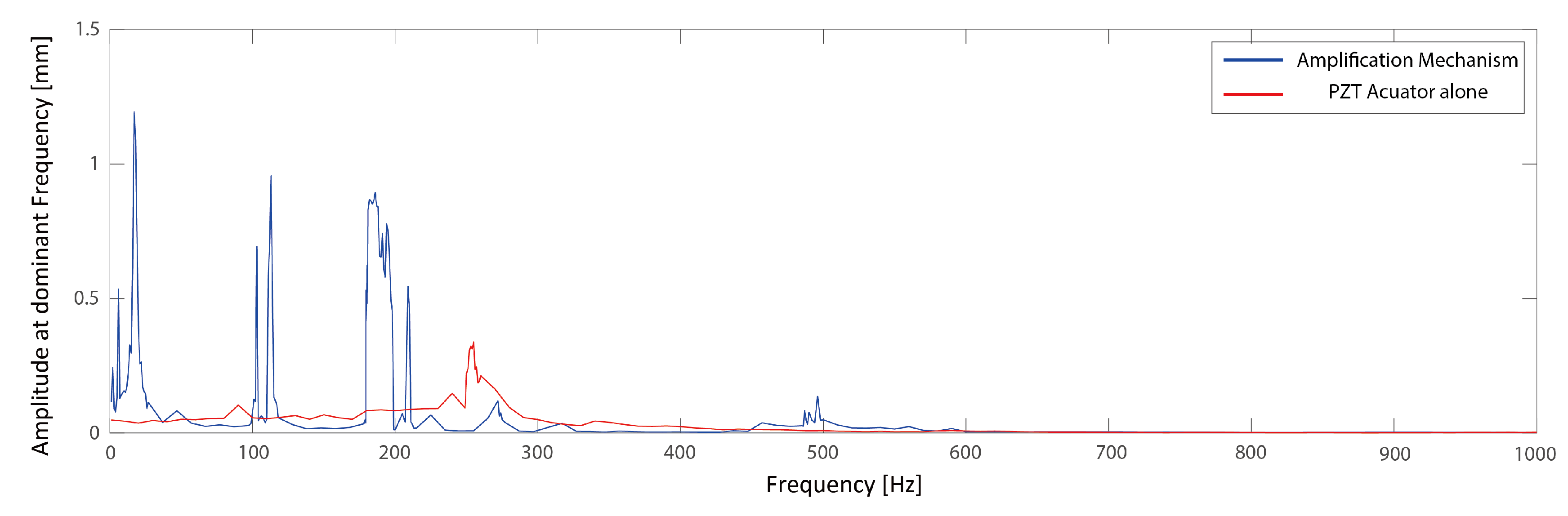
Experimentally, large output amplitudes are achieved at several input frequencies ranging from 1 Hz to 200 Hz, though the details of the response show significant discrepancies with the simple model described in
Section 2. Amplitudes of the largest frequency components of output motion after FFT analysis of individual time series are shown in
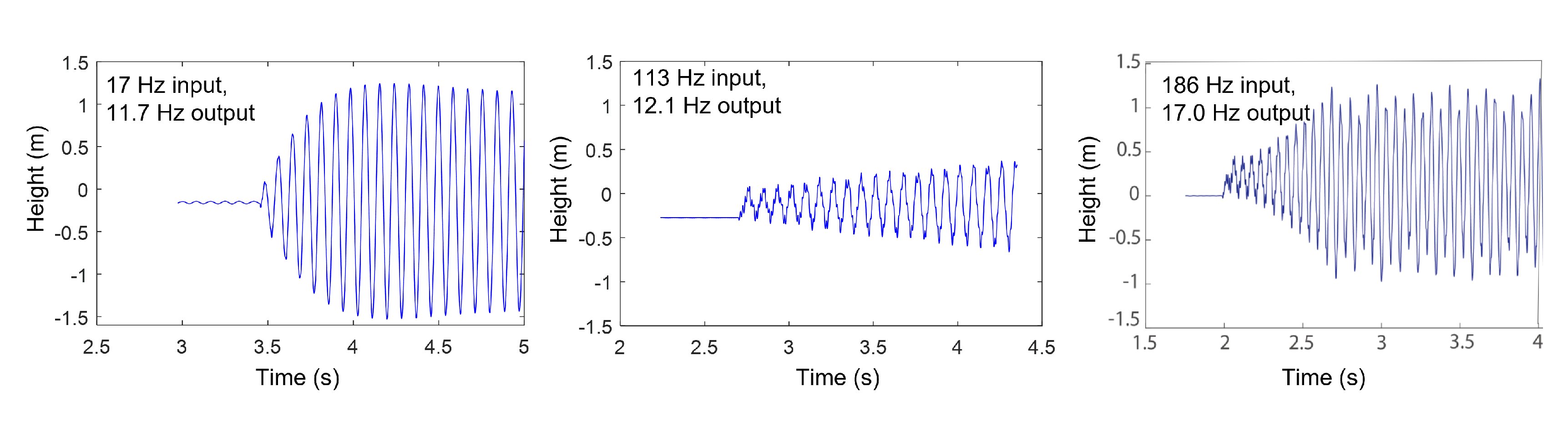
Figure 8, along with the comparable frequency response of the PZT bender alone. Three input frequencies, near 17 Hz, 113 Hz, and 190 Hz, achieve the largest output amplitudes. As predicted by the model, corresponding output oscillations occur at much lower frequencies (10 Hz–20 Hz), and increase with higher input frequencies. Time-series plots for mechanism output at those frequencies are shown in
Figure 9. The output oscillations are built up over widely varying numbers of impact cycles before reaching quasi-steady-state behavior, but can reach amplitudes of up to 1.2 mm, versus approximately 1 mm–2.2 mm amplitudes in simulation. In some cases, nearly sinusoidal motion is achieved. For example, in
Figure 10, a sample FFT for tip displacement is shown for 194 Hz input, showing a low-frequency output of 17 Hz as the dominant oscillation component, while only a tiny secondary peak is witnessed at the input frequency.
The differences between the simple simulation model and experimentally-observed behavior highlight limitations of the conceptual dynamics. First, dominant experimental output frequencies are higher than those predicted by simulation, though this may be attributed to uncertainty in material properties and layer thicknesses for the 3D-printed components. More interestingly, in experiments, fewer sub-resonant input frequencies produce large amplitudes than in simulation, while showing more uniform output oscillations than anticipated. Together, these observations suggest that there remain un-modeled dynamics that further influence stability (or lack thereof) of periodic limit-cycle behavior from the combined system. Finally, where the simulation predicts the largest output amplification at the PZT bender’s resonant frequency, experimentally, the nearby output resonance occurs at a reduced frequency (189 vs. 250 Hz) and with reduced amplitude. We hypothesize that additional interfacial forces may be present that lead to brief periods of adhesion between structures, increasing effective inertia of the bender, though this has not been verified.
Single-sided amplitudes at notable resonances are summarized in
Table 2. Output amplitudes are up to 110 times the amplitude of the bender alone at low frequencies. Comparing across frequencies, maximum mechanism output is approximately 3.5 times larger than the the largest amplitude for the bender alone.
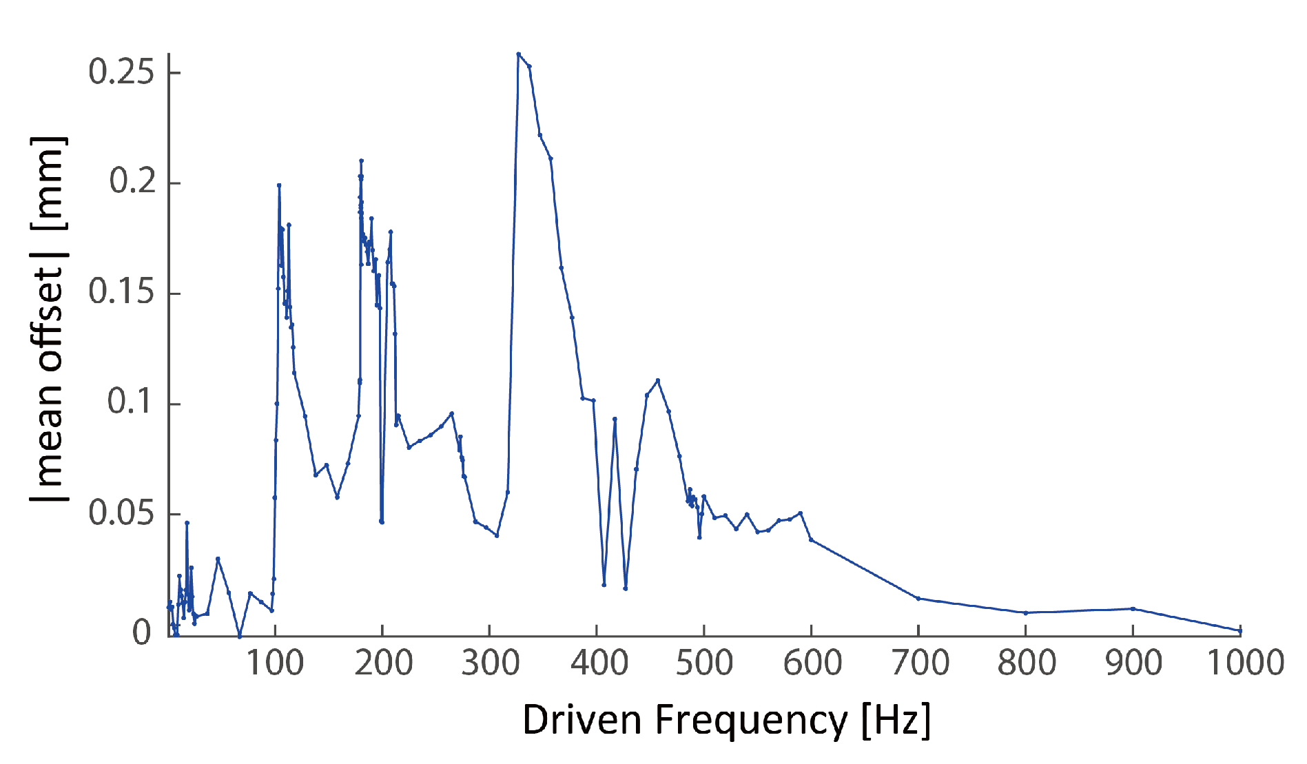
In addition to large oscillation amplitudes, the repeated impacts can drive mean tip displacements significantly away from its neutral position, sometimes with little accompanying oscillation. This primarily occurs with higher frequency excitations (300–600 Hz), producing repeated impact events that cause the output beam to rotate to a height above its neutral position. The mean tip displacement is shown as a function of input frequency in
Figure 11, and includes regions where tip displacements of 0.1 to 0.25 mm are achieved (versus PZT tip displacement alone of <0.01 mm) while oscillation amplitudes are small (<0.01 mm as observed in
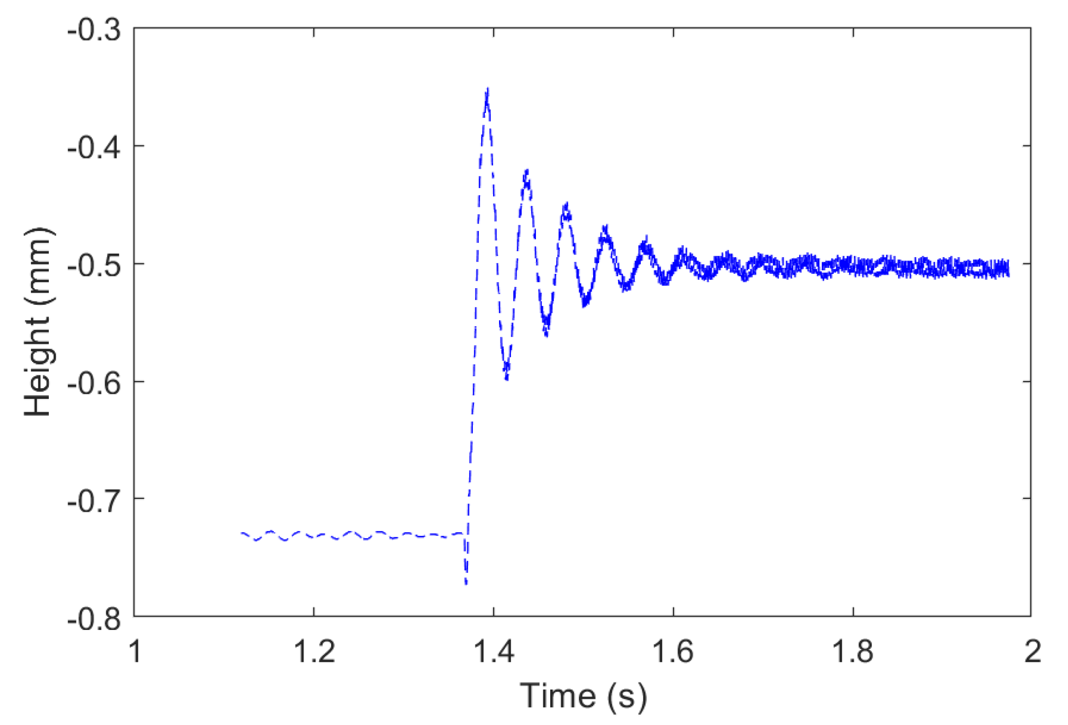
Figure 8), for a quasi-static, non-zero output displacement. A sample time response for output tip position after initiating a 40 V, 347 Hz square wave is shown in
Figure 12.
4. Discussion
Results described above suggest opportunities to achieve large, nearly periodic amplification of small piezoelectric transducer displacements, through repeated transducer impacts on a compliant structure. In this section, we discuss more subjective implications for use in small robotic applications.
4.1. Power Efficiency
For small or micro-scale autonomous robotics, power efficiency is a key criteria in actuator and mechanism selection. To evaluate impact actuator efficiency, we first calculate a nominal efficiency for the piezoelectric bender,
, as
where
is the dielectric constant of the piezoelectric material. For the PZT in use, ideal electrical-to-mechanical conversion efficiency is 7.5%. Conceptually, charge recovery mechanisms (as in [
21,
22]) can increase efficiency substantially, but this provides a basis for comparison to the impact-driven system.
The mechanical power transmitted to the mechanism is calculated from the power spectral density of the mechanism motion. To estimate power density from experimental results, we apply the approximation
in which
is the power density corresponding to frequency index
,
is effective vertical stiffness of the mechanism (measured as 6.54 N/m),
N is the number of samples,
is sampling rate, and
n is the index of each sampled time series data point. Power transmitted is calculated from the band power
where
is the mechanical power corresponding to the dominant frequency,
, and
is the bandwidth, selected here to be 10 Hz. To calculate the energy efficiency, the mechanical output power is compared to electric power input, calculated from capacitance of the PZT actuator,
C, voltage, and input frequency
In the prototype system, capacitance is known to be 28.2 nF, and the voltage amplitude, as previously mentioned, is 40 V.
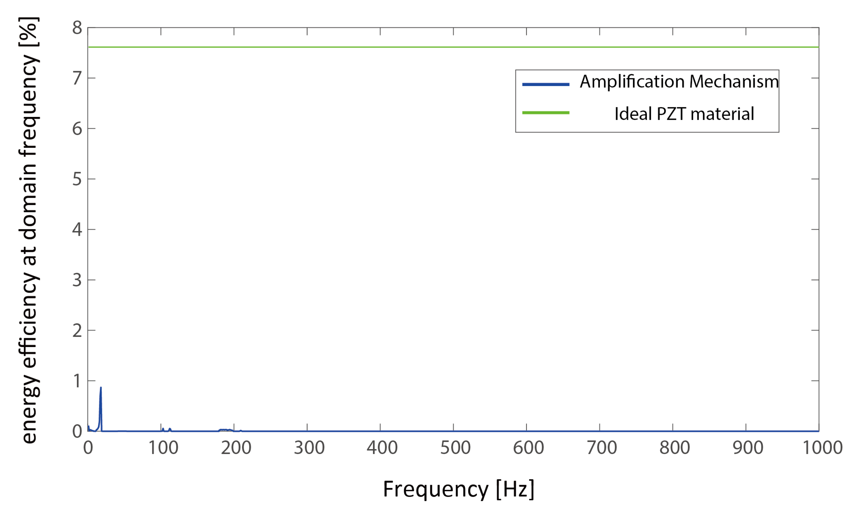
Figure 13 shows the estimated experimental efficiency of electrical energy transmission to the dominant mechanical oscillation component as a function of driving frequency. Maximum efficiency of 0.9% is achieved at 17 Hz. This represents substantial energy losses from the theoretical bender efficiency. However, it is similar to reported electrical-to-mechanical conversion efficiency for efficient shape memory alloy transducers, and large relative to electrothermal transducers, both of which tend to operate in similar frequency regimes [
23].
4.2. Loading Effects
Qualitatively, it was observed that static external loads applied to the amplification mechanism had a significant effect on effective driving frequencies and range of motion, as actuator behavior was very sensitive to the nominal gap between the PZT bender and output beam.
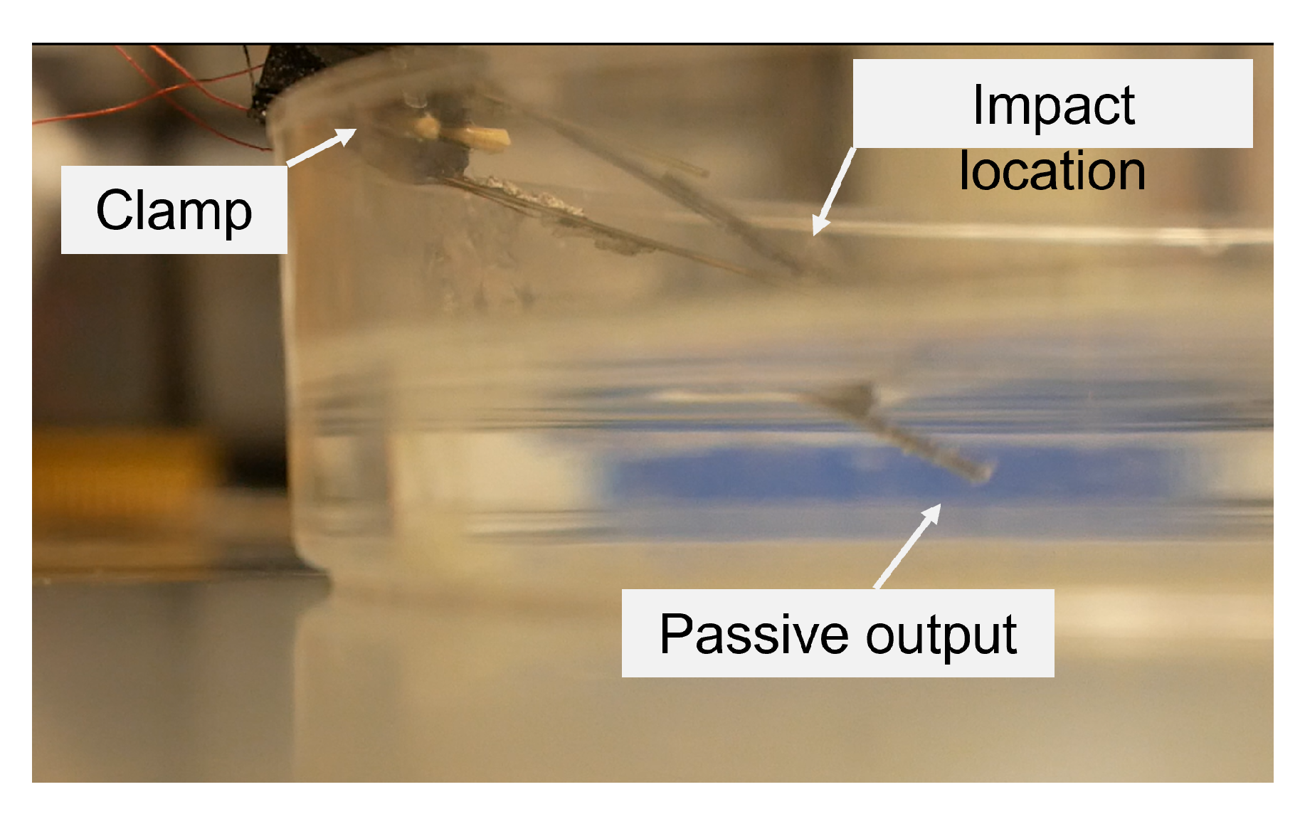
However, substantial displacements were still reliably obtained under large dynamic loads, as when operating the system with additional viscous or inertial resistance. For example, the passive section of the mechanism was immersed in water beyond the torsion bar (to avoid electrical short of the PZT bender), as shown in
Figure 14. With excitation frequency near 195 Hz, 1 mm output amplitudes were still recorded via video capture, with output frequency between 3 and 4 Hz.
In addition, some potential for non-reciprocal motion was observed due to the complex coupling of impact into both rotation and translation. Namely, in some experiments, the output beam was observed in video to translate back upward to a neutral position at a different angle than that at which it was driven downward. While this is a limited effect in the current design (approximately a 5 degree variation in angle with direction of translation), non-reciprocal motion, if reliably achieved, is important for low Reynold’s number locomotion through a fluid.
4.3. System Integration
To use compliant amplification of a piezoelectric transducer in a small, mobile robot, one goal would be to couple transducer vibration into oscillations of a compliant appendage structure that produces a useful gait or function, such as terrestrial or aquatic locomotion. Inspired by results from submersion of the basic mechanism, a simple bio-inspired aquatic robot was constructed as a proof-of-concept for integrating the impact-based mechanism into a small robot. It is important to note that no design or analysis for effective fluid dynamics behavior has been attempted at this time. Rather, the current experiment is intended to provide only basic insights into amplification mechanism integration into more complex systems.
The actuation mechanism was mounted in an elliptical frame carved by hand from balsa wood, with a fin-like acrylic structure attached to the output beam shown in
Figure 15. As in earlier experiments, significant displacement amplification is observed, along with frequency down-conversion.
Figure 16 shows motion of the assembled system in air. After assembly, natural frequency of the bender alone was found to decrease to 165 Hz, likely due to compliance in the bender mounting to the wooden frame. Under square-wave amplification, a maximum angular displacement of the fin was approximately 5 degrees, with highest amplitude for a 19 Hz square-wave input and 10 Hz dominant output frequency. Notably, the inertial coupling between structures was sufficient to oscillate the entire body relative to the fin when resting on a smooth surface.
The fish-inspired geometry was then enclosed by adhering a polyethylene film around the wooden frame, with epoxy applied to complete waterproof sealing where the output beam and fin extend through the film. Unfortunately, in the current assembly, this procedure was found to substantially impede motion, due to excessive epoxy needed to prevent the film from separating during operation. Nonetheless, after attaching additional mass sufficient to achieve approximately 50% submersion of the frame and fin and increasing driving amplitude to 100 V, maximum oscillation amplitudes of 1–2 mm remained achievable. In the half-submerged position, output fin frequency was estimated at 5 Hz from video capture data, with resonances observed under input frequencies of 5 Hz, 13 Hz, 19 Hz, and 65 Hz. Substantial further development is required to translate the proposed mechanism into effective locomotion, but these preliminary experiments suggest that there is some possibility for coupling piezoelectric bender vibration into variable fin oscillation frequencies even with substantial inertial and viscous loads.
5. Conclusions and Future Work
This paper presents an initial design for impact-based, dynamic amplification of small piezoelectric transducer displacement, with some capabilities for high-to-low resonant frequency conversion and output frequency tuning. In
Table 3, major performance attributes of the proposed mechanism are compared to other amplification strategies with similar size reported in the literature.
Table 3 highlights the unique large amplitude, low-frequency output of an impact-based approach to piezoelectric transducer amplification. Such functionality may provide opportunities for generating periodic appendage motions in small-scale robots where bio-inspired dynamics call for motion in much lower frequency ranges than are typical for piezoelectric transducers.
However, there remains substantial future work to complete a comprehensive study of this amplification strategy, both to fully understand dynamic behaviors and evaluate practical applications to micro-robotics. While the simple dynamic model introduced here captures several of the qualitative features of the proposed amplification mechanism, the impact event model, in particular, is too simplistic to fully predict experimental behaviors. Meanwhile, substantial prototype robot development, focusing on fluid coupling with oscillatory fin motion and packaging to avoid impeding mechanism motion, would be required to evaluate whether propulsion can be generated. Similarly, feasibility for generating legged locomotion would depend on gaining a better understanding of mechanism modeling and design for robustness over changing gravitational loads. Nonetheless, the approach may allow robot designers to generate near-periodic motion in unique operating regions for frequency, amplitude, and power in small-scale robotic systems.


