Article

STEP-NC Compliant Intelligent CNC Milling Machine with an Open Architecture Controller

by
Mahanama Dharmawardhana
1,2,
Asanga Ratnaweera
3,* and
Gheorghe Oancea
2,*
1
Department of Manufacturing and Industrial Engineering, Faculty of Engineering, University of Peradeniya, Peradeniya 20400, Sri Lanka
2
Department of Manufacturing Engineering, Transilvania University of Brasov, B-dul Eroilor 29, 500036 Brasov, Romania
3
Department of Mechanical Engineering, Faculty of Engineering, University of Peradeniya, Peradeniya 20400, Sri Lanka
*
Authors to whom correspondence should be addressed.
Appl. Sci. 2021, 11(13), 6223; https://doi.org/10.3390/app11136223
Submission received: 13 June 2021 / Revised: 29 June 2021 / Accepted: 30 June 2021 / Published: 5 July 2021
(This article belongs to the Section Robotics and Automation)

Abstract

:
A STEP-NC or ISO 14649 compliant machine controller is developed, using Open Architecture Control technology for a three-axis Computer Numerical Control milling machine in this research. The controller is developed on a Raspberry Pi single-board computer, using C++ language. This new development is proposed as a low-cost alternative to ISO6983 standard, ensuring continuous integration in the CAD/CAM/CNC chain in machining; thus, it broadens the spectrum of problems handled by conventional CNC systems. The new machine controller is intelligent enough to extract geometrical and manufacturing parameters, cutting tool data, and material data from the STEP-NC file. Accordingly, tool paths for machining can be generated in the controller itself. The shop floor level modification of parameters and the possibility of regeneration of new toolpaths is an added advantage of this new controller. The modified or improved version of the STEP-NC file can be sent back to the CAD/CAM system to close the CAD/CAM/CNC chain. Machine condition monitoring can be achieved by connecting sensors through an available slave I/O board. In the present development, the current drawn by each servo motor is fed back to the controller for cutting condition monitoring. A laboratory scale three-axis CNC milling machine is developed to test the performance of the newly developed controller. The accuracy of positioning, perpendicularity of axes and linearity of this machine are experimentally verified through standard tests. The STEP-NC compliance of the controller is tested and verified, using a STEP-NC program derived based on a sample program given in ISO 14649 standard.

1. Introduction

Computer Numerical Control (CNC) machines play a vital role in product manufacturing. Traditionally, CNC machines have been programmed according to ISO6983 [1] standard throughout the last half a century or so. This standard defines a low level programming language, which describes only the cutter location path and switching instructions [2]. A limited set of information written with G and M codes are sent to the CNC machine for execution. The CNC machine tool just acts as an executing machine, having no intelligence. Therefore, due to the unavailability of information about work piece, cutting tools, machining features and machining parameters, the shop floor level modifications cannot be entertained, except for the feed rate and spindle speed adjustments. These details are not transferred to the machine tool controller, although they are available in CAM software. Since ISO 6983 covers only a limited set of facilities, CNC machine vendors extended the G and M code to define their own specific functions, such as custom fixed cycles. This makes a specific post processor required for each and every CNC controller because of the vendor-specific G and M codes. Therefore, the interchangeability of CNC part programs between different controllers is restricted [3].
In order to address these problems, a new standard, ISO 14649 [4], popularly known as STEP-NC, was recently introduced. This new standard provides a data model for a new breed of intelligent CNC machines [3]. The main objective of STEP-NC is to integrate data available at the design stage with CAM and CNC. Special provisions are included in the new standard to prevent data loss during the CAD-CAM-CNC chain [2]. Further, ISO 14649 standard introduces a new data format in order to transfer the information available at the CAD/CAM stage, such as features to be machined, workpiece data, cutting tool data, technological data, operations and their sequence and much more, to the CNC machine. Accordingly, the toolpaths can be generated by the CNC controller itself since all the information to generate cutter locations is available at the CNC machine. As machine-specific information is not used in ISO 14649, the post-processor requirement is eliminated [5].
Almost all commercial CNC machine controllers at present were developed on vendor-specific architectures. Therefore, the expansion hardware and software modules must be purchased from the same vendor for compatibility. The availability of those modules is limited and decided by the vendor, not by the customer. Accordingly, these commercial controllers cannot be extended to STEP-NC compliant controllers. As such, Open Architecture Controller (OAC) development technology is used to develop STEP-NC compliant controllers [6,7,8].
OAC is defined as an open system, which provides capabilities that enable properly implemented applications to run on a variety of platforms from multiple vendors, interoperate with other systems applications, and present a consistent style of interaction with the user [9]. Further, OAC systems are independent of manufactures’ proprietary, and thus a customer gives the flexibility of plug-in required additional hardware and software from any developer into the system. This allows the integration of application programs, control algorithms, and hardware accessories developed by diverse manufacturers [10]. Overall, OAC technology is a neutral vendor control system interface that provides interaction, interoperability, portability, and scalability specifications.
As personal computers (PCs) gained popularity, it became a better choice in the industry as a hardware platform for open architecture CNC systems. High performance to price ratio of a PC is one of the main advantages of using a PC in open architecture CNC systems [11]. Some of the PC-based OAC developments reported in the literature are described below.
A PC-based OAC for the existing Denford Novamill ATC 3 axis CNC milling machine was developed on the LabVIEW software platform by Elias et al. Two interpreters were developed to read ISO 14649 and ISO 6983 format files and convert them to generic toolpaths [12]. Yusof and Latif made further improvement for the above controller by introducing a PC-based hardware platform with a motion control card and a software platform using Windows, JAVA/Visual Studio, ST developer and LabVIEW [13]. Another improvement was made by Latif et al. by introducing 3D simulation and machine motion control with a drill bit changer. Software and hardware integration was done on the LabVIEW environment [14].
Another PC-based STEP-NC complaint milling machine was developed with OAC by Lee et al. The STEP-NC in XML format is used in this machine. The controller is capable of modifying the given XML format STEP-NC file through its limited intelligence in the early stages and sends it back to the controller for processing [15].
Calabrese et al. used an embedded microcontroller to develop a STEP-NC compliant CNC controller. This was realized in a two-degrees-of-freedom plasma-cutting CNC machine, using a Rabbit microprocessor RCM3700 [16].
The above short review highlights the OAC type STEP-NC compliant CNC milling machines developed by different researchers. Most of these developments require expensive motion control cards and data acquisition cards [17]. Some of them depend on commercially available third party software, such as LabVIEW, MATLAB [11,13,18], etc.
Machine condition monitoring and improvement can be achieved by introducing sensors on the CNC machine. Narayan et al. investigated the feasibility of using an accelerometer, current sensor and sound detector to collect data from a CNC machine [19]. Downey et al. used an industrial-type CNC machine to investigate cutting tool wear by introducing three sensor technologies; force, acoustic emission and vibration [20]. A multi-sensor-based tool condition monitoring system was developed by Zhang et al. Vibration, cutting force and power data were collected with the cutting parameters to monitor the tool condition and estimate the tool life [21].
Mikolajczyk reported the improvement of an existing milling machine to a numerical control machine with the help of a developed software called PCMill [22]. In the last decade, single-board computers (SBCs) have become popular because of their low power consumption, smaller size, low cost, ability to interact with the outside world with the available General Purpose Input–Output (GPIO) facility, ability to run on free operating systems, and availability of wireless connectivity. Almost all of these SBCs use various flavors of Linux open-source operating systems. Out of the number of available SBCs on the market, ARM-based SBCs are becoming increasingly advanced and strong [23]. Recently, Raspberry Pi was considered one of the most popular SBC in automation and activities related to Internet of Things.
An investigation on the transition from a PC-based CNC control system to an ARM-based Raspberry Pi CNC control system was carried out by Grigoriev et al. A Raspberry pi SBC-based controller was designed for an existing multi-tasking turning and milling machine in this research. The authors concluded that the computing resources of ARM-based SBCs are adequate for performing the main tasks of multi-channel, multi axes CNC machine tools [24].
There are two popular free software available to control CNC machines, 3D printers, robot arms, etc. The first one, LinuxCNC, runs on Linux, Ubuntu and Debian distributions. LinuxCNC has an interpreter for ISO 6983, a Human–Machine Interface (HMI) and real-time motion planning system. The second one is grbl software, which also facilitates the ISO 6983 Standard data interpretation. The grbl software can be implemented in Arduino Uno microcontroller to drive a CNC machine. The Java-based cross platform application called Universal Gcode Sender or a similar application can be used as the interface between the microcontroller and the computer. Both of these applications can interpret only ISO 6983 standard data, and thus do not comply with STEP-NC standards.
Wagner C. demonstrated a woodworking router operate on Raspberry Pi with Linux CNC software [25]. Winegarner T. used Raspberry Pi and Universal Gcode Sender to control an existing router [26]. Both of these implementations are merely replacements of a PC with a Raspberry Pi SBC. Another CNC router implementation was done by Ballard R. on Raspberry Pi with the new version of grbl called grblHAL [27]. The grblHAL was developed especially for 32-bit operating systems and processors, such as Raspberry Pi, in contrast to grbl, which was released to 8-bit controllers, such as Arduino Uno. An advanced g-code sender, bCNC, was used with the grblHAL instead of the Universal Gcode Sender. The bCNC is a robust and fast cross platform (Windows, Linux and Mac) application written in Python to transfer data and handle other functions. However, none of these developments comply with STEP-NC standards.
In this research, the authors developed a STEP-NC complaint CNC milling machine that can be used as a test rig for future research. A Raspberry Pi 3 Model B+ SBC was used as the main controller of the CNC machine. The Raspberry Pi OS (previously called Raspbian) operating system-based environment was used for all related developments. The main coding was written in C++ programming language and HMI was programmed with the aid of Qt for flexibility and to achieve fast data update on the screen. Raspberry Pi SBCs are readily available in the market at a low cost. Unlike for PC-based systems, built-in GPIO pins of the SBC connect signals from and to the machine, which is an added advantage. A complete standalone OAC software is developed without using expensive commercial software. It is worth noting that no OAC STEP-NC-compliant CNC developments carried out on SBC are reported in the literature.
The developed machine can be used to enhance the capabilities introduced in STEP-NC standard. The slave IO card supports more analog and digital signals to connect sensors to monitor cutting conditions. This will be helpful to predict better cutting conditions and regenerate the tool path for machining.
The micromilling technology refers to ultra-precision machining with sub-micron accuracies. The conventional cutting conditions cannot be used in micromilling by simply downscaling. Uriarte et al. proposed a tool for the selection of micromilling process parameters [28]. Lamikiz et al. proposed a utility for toolpath optimization and to estimate cutting forces in machining complex surfaces [29]. Both of these implementations are planned for the CAM stage. Such implementations can be integrated into the newly developed controller itself since it is operating on OAC and STEP-NC.
The quality of the machined product is mainly dependent on the accuracy of the machine tool. Errors in machining reduce the accuracy of the machine and affect the quality of the end product. Geometrical errors, thermal errors, kinematic errors, stiffness errors and errors due to the deformation of cutting tools and machine tools are considered the primary sources of errors related to machine tools [30]. Out of those errors, the geometrical errors that originate due to mechanical imperfections are the highest contributors towards the errors in machine tools. In addition, the thermal errors due to the temperature variations of the machine resulting from internally generated heat and environmental changes also have a significant negative impact on the accuracy of a machine tool [31].
In this paper, hardware development of the newly developed CNC machine is described in Section 2. The mechanical system and electrical system are detailed in this section. Software development that includes control algorithms and HMI design is described in Section 3. Section 4 includes the verification of the execution of the STEP-NC program.

2. Hardware Development

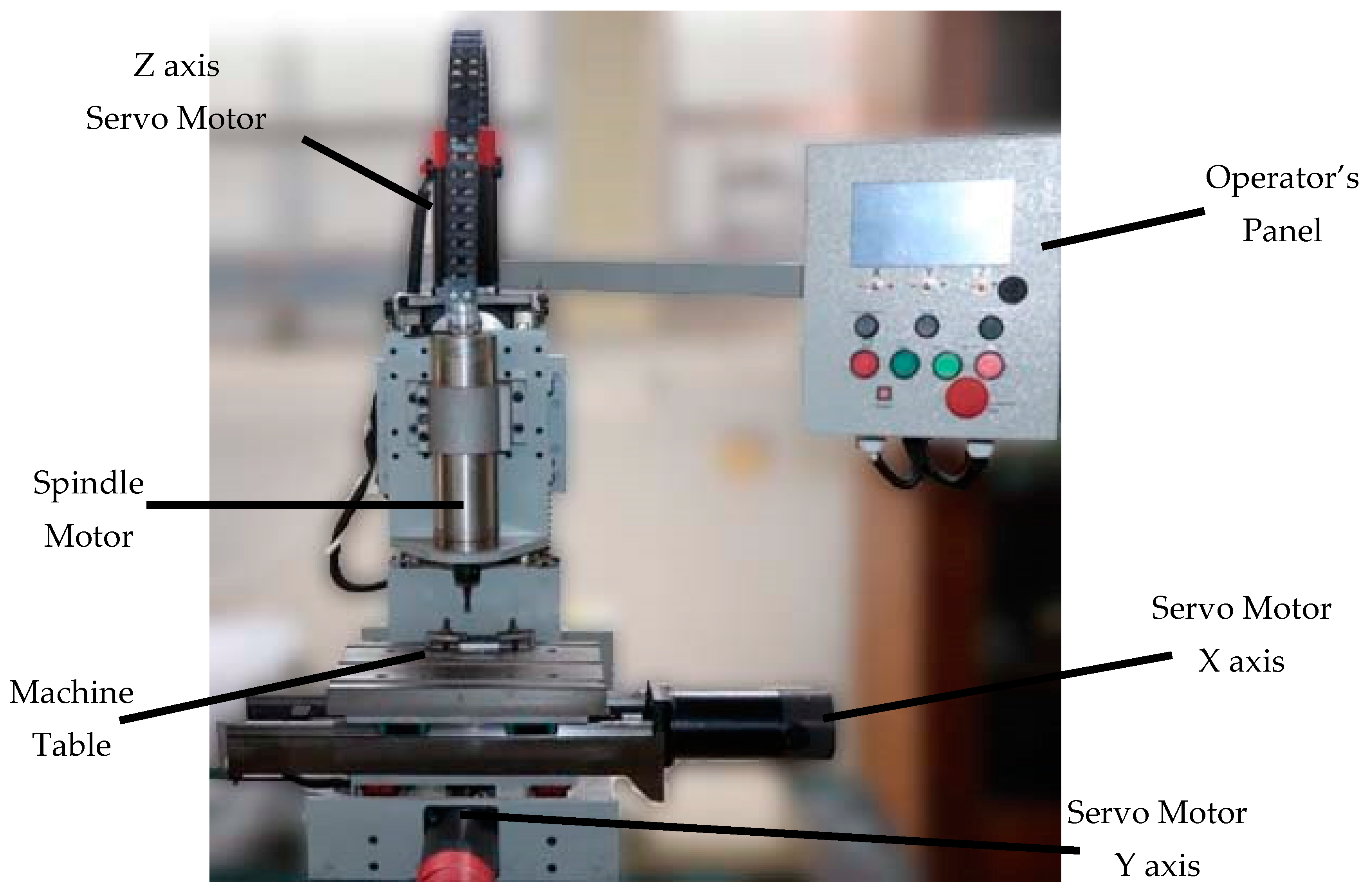
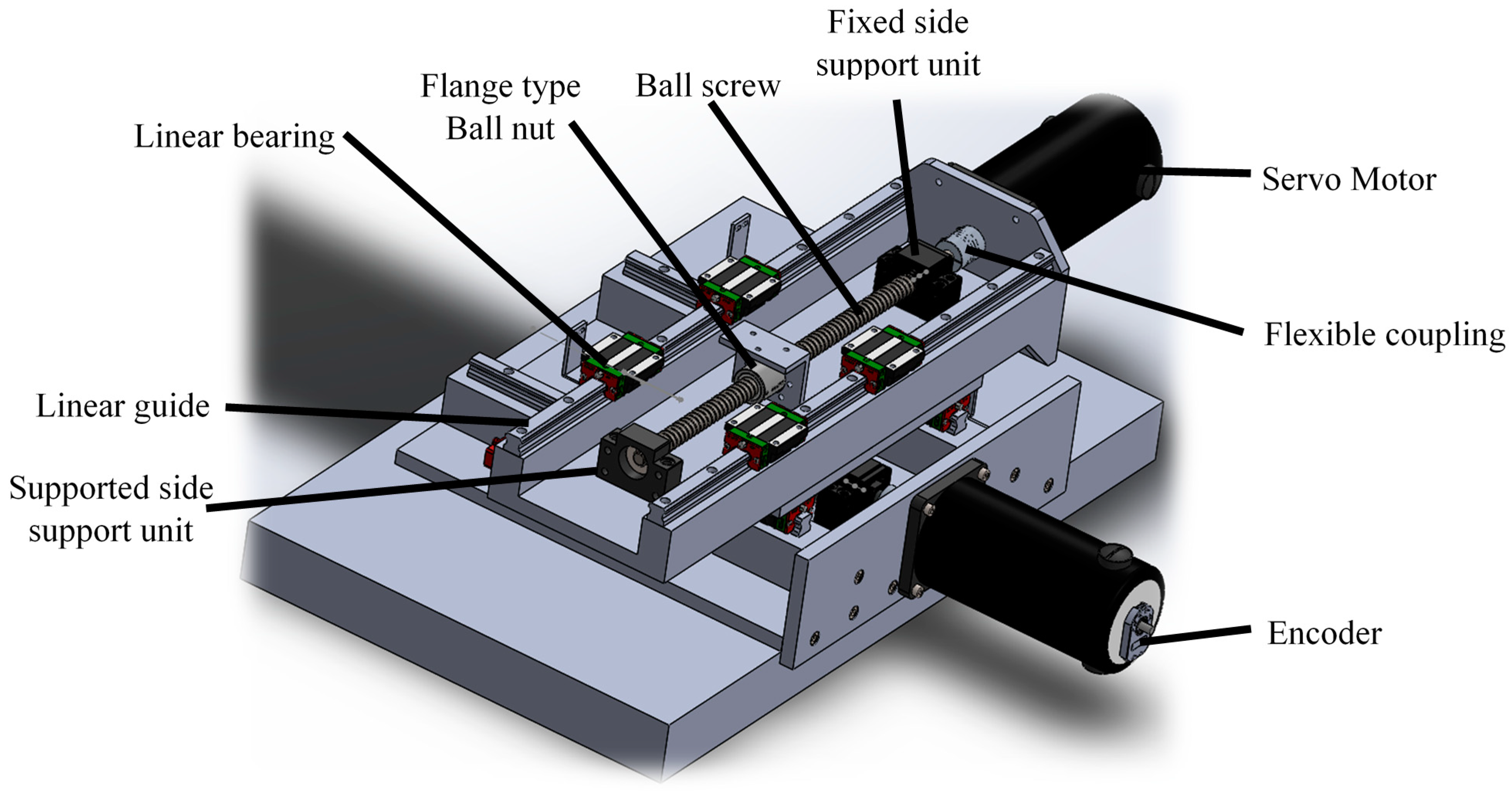
2.1. Mechanical System

The structure of the machine is one of the important components of a machine tool, which directly affects its rigidity, damping response, and dynamic stiffness. Hence, the machine saddle, mounting structure of the headstock, and the worktable are designed and manufactured with cast iron, and the rest of the structure is fabricated with mild steel. Figure 1 shows the actual machine. The cast-iron saddle moves on the main guideways in the Y direction, and it carries the worktable, which moves in the X direction as shown in Figure 2. All axes are driven through ball screws and linear guideways to reduce backlash and to achieve the required precision.
A ball type of 15 mm and linear guideways with a basic static load rating of 16.97 kN are used in the machine for precise and accurate positioning. Each guideway supports two sliding blocks to carry the weight of the machine table, work holding device, workpiece and cutting forces. Sliding blocks are of the self-aligned type to absorb any installation errors due to surface irregularities. A 16 mm diameter, single-start ball screw with 5 mm lead is used to move the worktable and headstock through a flange-type ball nut. The maximum permissible travel distance error of the ball screw is ±50 μm/300 mm, which falls under the accuracy grade of C7 (ISO 3408). Rectangular, supported side and fixed side support units are used to hold the ball screw from the free end and motor end of the ball screw, respectively.
The cast-iron machine table is 300 × 200 mm in size and has three numbers of Tee slots for mounting workpieces. The z axis moves in the vertical direction and carries headstock where the spindle motor is housed. The spindle has a strong influence on material removal and the quality of machining. The main function of the spindle is to rotate the tool precisely and transmit the required energy to the cutting zone. A 2.2 kW, water-cooled spindle motor is selected to achieve heavy material removal rates. The spindle motor supports ER20 standard collets to mount cutting tools securely with a collet nut. Overall specifications of the developed machine are given in Table 1.

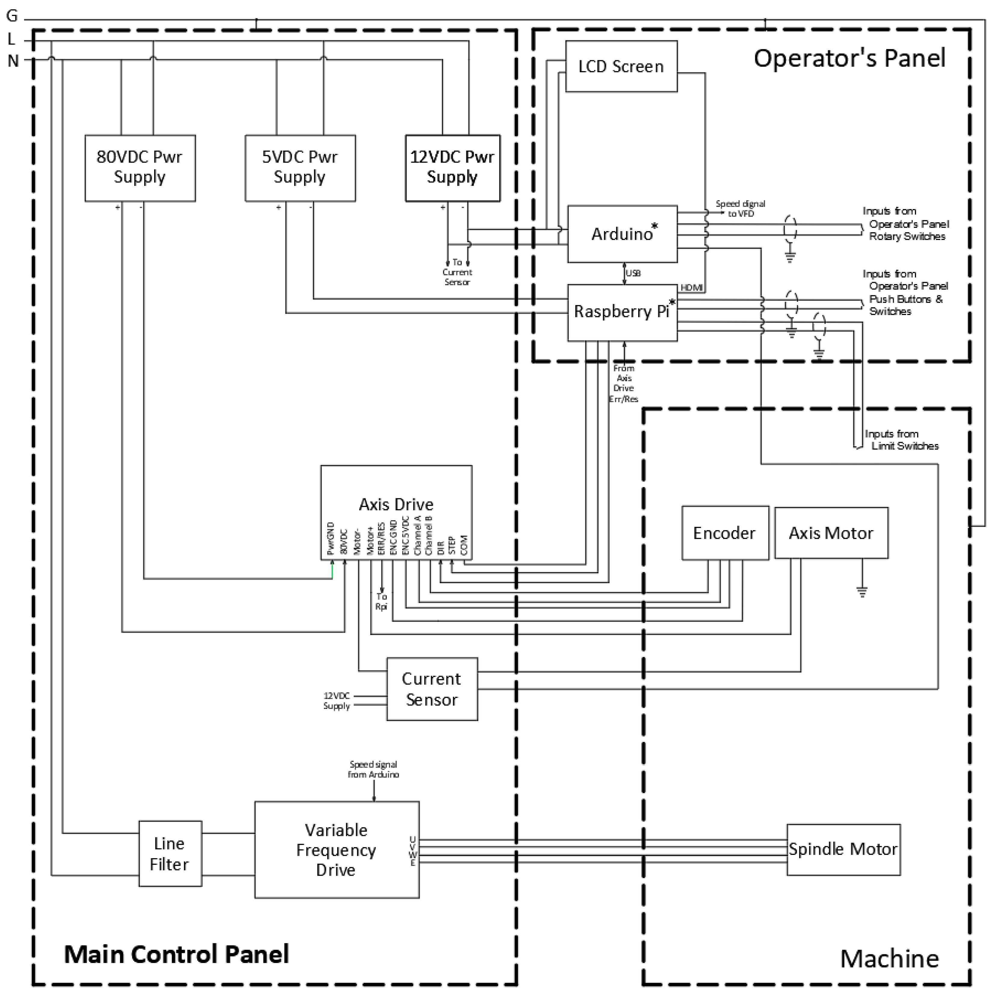
2.2. Electrical System

The electrical diagram of the CNC machine is shown in Figure 3. The machine is fitted with two control panels. The one at the front end, as shown in Figure 1, is the operator’s panel. The other one is the main control panel and is placed at the backside of the machine. The machine is powered with a 230 V-50 Hz power supply through the main control panel. The electrical power required by the operator’s panel, 12VDC and 5VDC, is supplied from the main control panel. Other power supply units required to feed servo motors and the spindle motor are also housed inside the main control panel. Electrical panels and the metal structure are connected to the ground for the safety of the operator. Overcurrent protection of the circuits and equipment is taken care of by an overcurrent breaker inside the main control panel. All field wiring from and to the machine is carried through the flexible conduits to minimize interference.

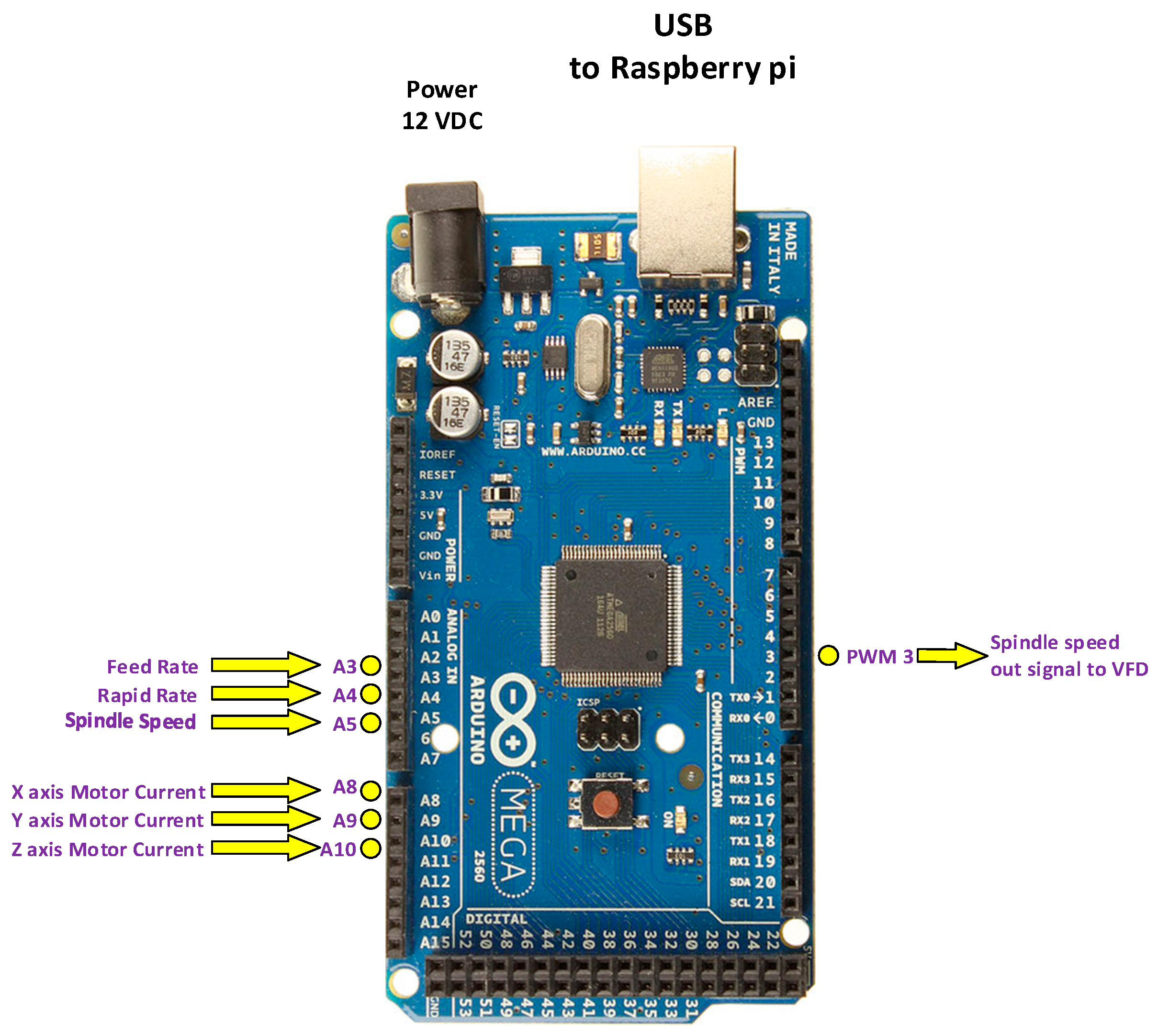
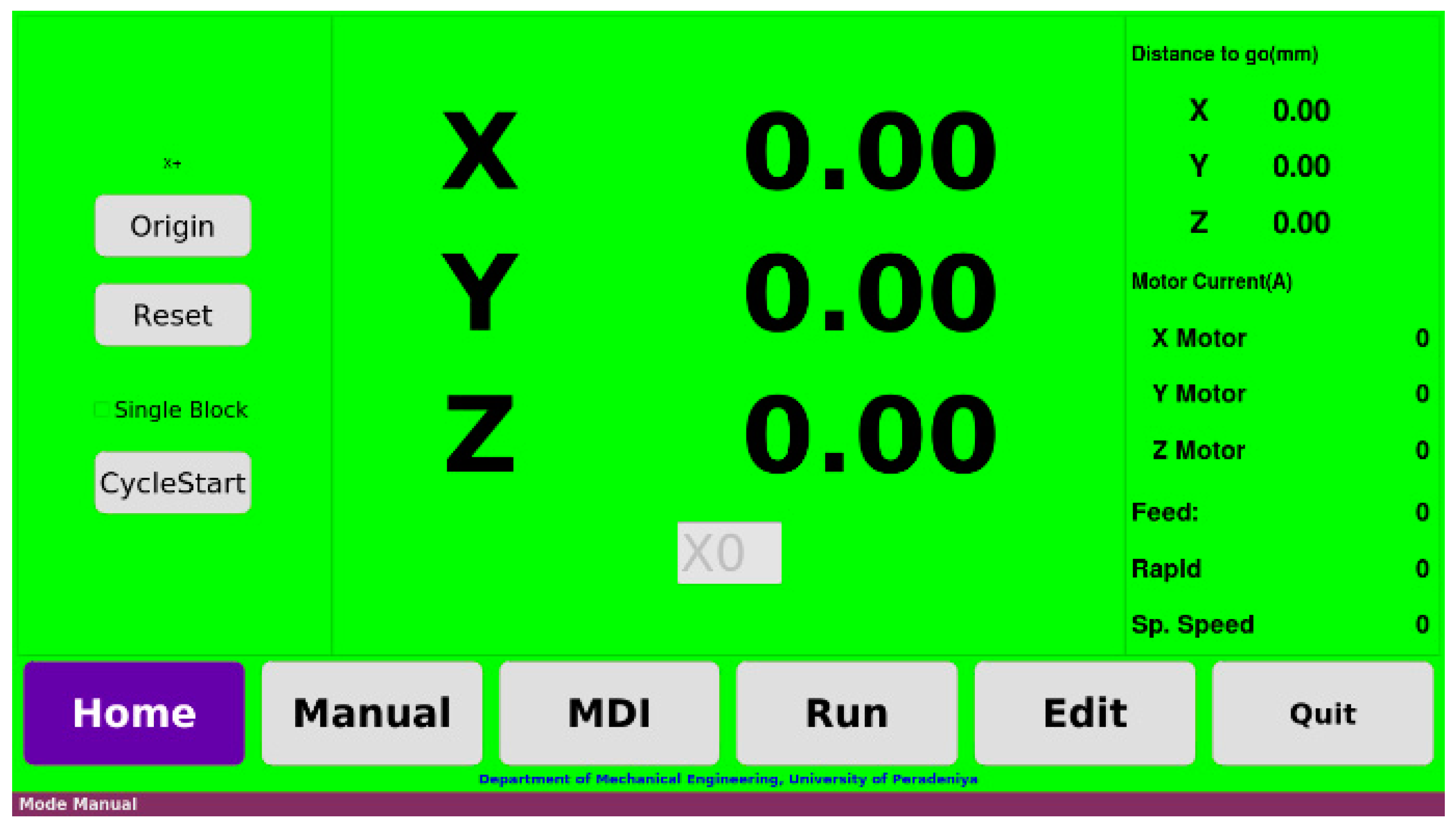
2.2.1. Operator’s Panel

The operator’s panel includes the main controller, IO card, manual controls of the machine, and touch screen LCD as HMI. The Raspberry Pi OS operating system driven Raspberry Pi SBC is the main controller of the CNC machine. The computer is powered by a 64-bit Broadcom BCM2837B0 Cortex-A53 quad-core processor running at 1.4 GHz.
Most of the digital inputs and outputs of the system are connected to a 40 pin GPIO pin header. Main digital input signals are the operator’s panel control keys and axis end limit switches. Three (Pulse Width Modulated) PWM output signals (GPIO 18, 13 and 19) are used to drive three servo motors for axes control. Another three digital output signals (GPIO 22, 20 and 26) are used to control the direction of rotation of the motors. Complete pinout is given in Figure 4.
There is no analog signal input facility on this SBC. Therefore, the Arduino Mega 2560 microcontroller is used as a slave input–output board to establish the analog inputs. The communication between Raspberry Pi and the Arduino Mega controllers is done through USB ports, using the Firmata library. Arduino Mega has 16 numbers of analog input pins and 15 numbers of pins, which can be configured as PWM outputs. Analog signals received from motor current sensors (A8, A9 and A10), the feed rate controller (A3) and the spindle speed controller (A5) are connected to the Arduino microcontroller as shown in Figure 5. The calculated spindle speed is also sent to the VFD through PWM pin number 3.
A general purpose 7” touch screen LCD monitor and driver circuitry are also enclosed in the operator’s panel. A user-friendly HMI was developed using the touch screen. Further, a mouse and a keyboard were also installed for easy operation.

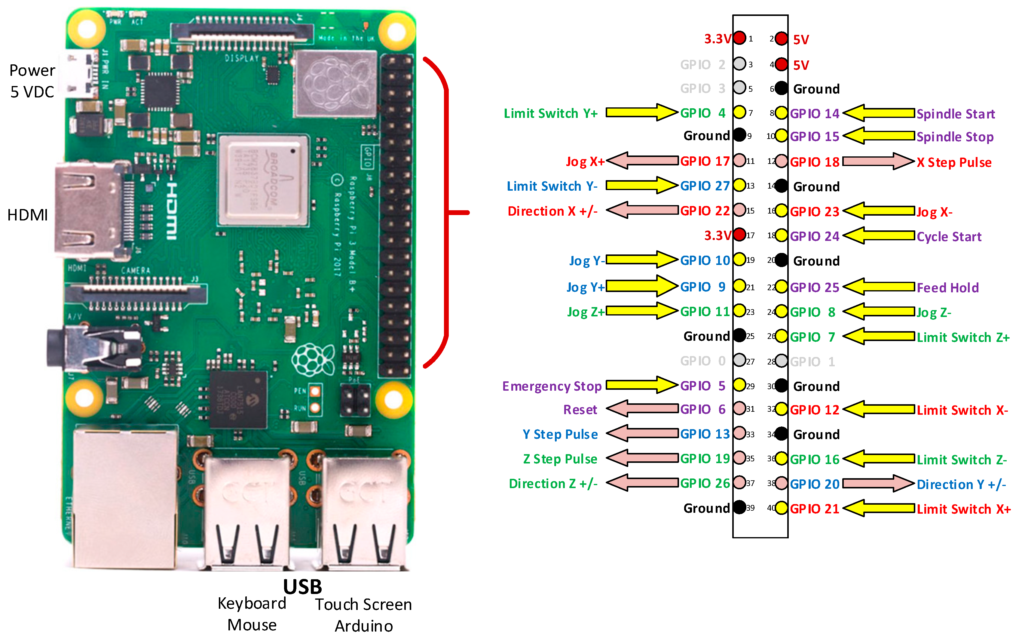
2.2.2. Main Control Panel

Power supply units, axis drives, current sensors, and Variable Frequency Drive for the spindle drive are housed in the main control panel.
There are three power supply units used in the electrical system of the CNC machine. The Raspberry Pi controller is powered by a 5 VDC regulated switch mode power supply. This power supply is dedicated to the main controller and directly-connected circuitry for smooth operation. A 12 VDC switch mode power supply is used to supply power to the Arduino Mega controller and LCD touch screen. The third power supply, having an output of 80 VDC, is specially designed for driving stepper or servo motors. A toroidal transformer and two large 10,000 μF capacitors in this power unit drive all three servo motors with minimum ripple.
“G320X Servodrive” manufactured by Geckodrive Inc. was used in the axis drive. It controls a number of functions in the system. Mainly, it drives the servo motor, according to the direction and step pulse signals received from the SBC controller. At the same time, AMT102 rotary encoders manufactured by CUI Inc., which are used as feedback devices, are also connected to the axis drive. The encoders are fixed at the backend shaft of the servo motor, and they generate an angular positional feedback signal, according to motor shaft position. The axis drive supplies power to the encoder and accepts feedback signals coming from the encoder. There are three trim pots on the servo drive itself to set Proportional, Integral, and Derivative (PID) constants of the control loop to precisely damp the motor. An internally closed PID loop ensures that the motor maintains accurate positioning. This gives the precise and accurate position control required for the CNC machine.
The servo motor current varies according to the cutting forces during the milling operations. There are three current sensors connected to measure instantaneous currents drawn by each servo motor. The current sensor, CZH-LABS D-1020, emits an analog signal proportional to the current drawn through the sensor. This signal is fed to the Arduino microcontroller and used for machine condition monitoring function.
The other important unit in the CNC machine is the spindle motor and the spindle speed control unit. A three phase 2.2 kW, the 8A spindle motor is used in the developed machine to withstand fairly high cutting forces. The maximum spindle speed of the selected spindle motor is 24,000 rpm. According to the required machining conditions, the spindle motor speed should be adjusted. This function is achieved by changing the frequency of the motor supply, using a Variable Frequency Drive (VFD). A three-phase VFD with a 2.2 kW rated output power is selected to control the spindle speed. The analog terminal control method is used to command the required speed to the motor. An analog voltage value between 0 V to 5 V, according to the required spindle speed, is set through the Arduino controller to obtain the required speed.
The VFD is one of the nonlinear loads connected to the supply in the control panel, and it creates harmonic currents and voltages to the connected power supply. Besides harmonics, VFD also generates radio frequencies and electromagnetic interferences frequencies in the range of 0.5 MHz to 1.7 MHz, and 1.7 MHz to 30 MHz, respectively [32]. This creates electrical noise in the electrical system of the machine. Unstable operation of electronic circuits and false triggering of the GPIOs of the controller may result from this interference. To avoid these problems, a single-phase double-loop two-stage EMI filter is introduced at the power supply conductors of the VFD.
To operate CNC machines reliably, all electronic and electrical circuits are connected to a common signal reference ground. This signal reference is common to the CNC controller and other electronics, which are connected to the ground terminal of the machine. The grounding of the electrical circuits of a CNC machine has a greater influence on its susceptibility to different sources of noise and stray currents [33]. Therefore, shielded cables are used for all signal-carrying conductors, and the shield is grounded only at one end of the cable. In addition, inside the control panels, signal cables are isolated from the internal power cables as much as possible to avoid any interference.

2.2.3. Servo Motor and Encoder

Three brushed, skewed rotor DC servo motors are used to position all three axes precisely. This 1.6 Nm motor can draw a continuous current of 7.8 A, at a 90 VDC supply. This is fitted with a capacitive type, quadrature, incremental rotary encoder, AMT102, manufactured by CUI Inc. The maximum resolution of the encoder is 2048 pulses per revolution (PPR). The resolution can be selected by setting the available DIP switches on the encoder; the 1000 PPR setting is selected to obtain the preferred linear resolution of axes.

2.2.4. Spindle Motor Control

The speed of the spindle motor is controlled by the VFD controller. Mainly, the VFD can be commanded by two methods: analog terminal control and serial communication through RS485 standard. The analog terminal control method uses 0–12 V analog voltage control or 0–20 mA current loop control. In this development, analog terminal control with voltage control is used. According to the position of the spindle speed control knob on the operator’s panel, an analog voltage is generated from the slave I/O board. This voltage signal drives the analog control terminal of the VFD to rotate the spindle at the required speed. The details of the major electrical components are given in Table 2.

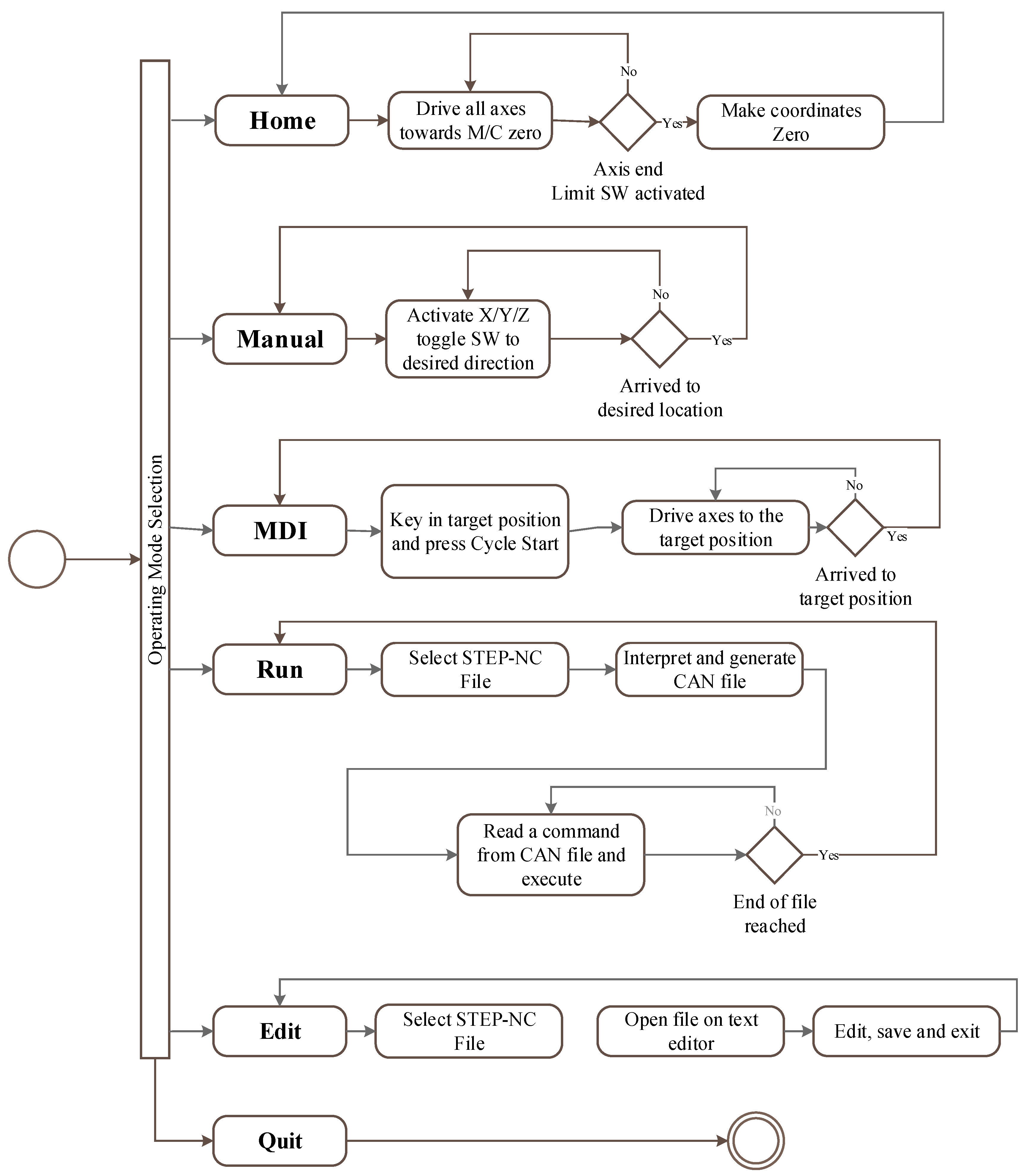
3. Software Development

Numerical Control Kernal (NCK) was developed on a Raspberry Pi 3 B+ single-board computer, using C++ programming language. The HMI was developed with the aid of Qt. The user is facilitated with five operating modes, namely, Home, Manual, MDI, Run and Edit (Figure 6).
Five main software modules (Figure 7) are incorporated in the NCK, namely, motion control modules, file read, interpolator module, ISO 14649 interpreter module, digital and analog input–output module and HMI module.
The ISO 14649 interpreter module begins by reading STEP-NC part21 file to the CNC controller. An open-source software developed by National Institute of Standards and Technology (NIST) is used to interpret the file. The interpreted and processed data are saved as a Canonical Machining Command (CMC) file [34]. Canonical commands are atomic instructions, which produce a tool motion or a logical action [35]. Data inside the CMC file are then extracted by the data extractor module. The data are sent to the interpolator module if a tool motion command is extracted. Otherwise, the extracted command is processed individually. The interpolator module accepts the linear motion commands STRAIGHT_TRAVERSE(), STRAIGHT_FEED() and the circular motion command ARC_FEED(). All the other canonical commands are directed to the logical action processing module.
A machining trajectory is planned, according to the motion commands passed from the CMC file. The interpolator module controls the tool movement along the proper trajectory. Linear and circular interpolation is used to command the axis movement along its trajectory.
To have a smooth movement of the machine, acceleration and deceleration should be imposed during the start and end of a block. Generally, there are two kinds of acceleration and deceleration control methods: control of acceleration/ deceleration after interpolation (ADCAI) and before interpolation (ADCBI) [36]. The path command errors cannot be eliminated in the ADCAI method, which limits its machining accuracy. In contrast, path command errors are eliminated in the ADCBI method, theoretically [37]. As such, the ADCBI method with a trapezoidal velocity profile is used in this development.
A trapezoidal velocity profile is applied with preset acceleration and deceleration values to reach the commanded position by interpolation. The trapezoidal velocity profile is easy to implement, computationally less intensive, and thus recommended for low-speed, low-cost machines.
There are two main methods to develop linear and circular interpolation algorithms. The first method is to keep a constant displacement with a varying interpolation period. The second method is the opposite of the first method, in that it keeps a constant interpolation period with varying displacement [38]. In this development, the first method of the interpolation algorithm is applied with constant displacement.
The linear interpolation algorithm is developed based on Equation (1). The controller is expected to drive from point Ps(Xs,Ys) to Pe(Xe,Ye) along a linear trajectory as shown in Figure 8. Consider two points on the line Pn(Xn,Yn) and Pn+1(Xn+1,Yn+1) placed δ t distance away from each other. The interpolation interval δ t is considered to be the constant displacement along the line. Coordinates of the new point Pn+1 with respective to the point Pn are calculated as follows:
δ x   = δ t   cos ( θ ) X n + 1   = X n   + δ x Y n + 1 = Y n + ( X n   X s ) ( X e X s )   ( Y e Y s )
Similarly, Equation (2) is applied when a circular path to be followed by the machine table from point Ps(Xs,Ys) to Pe(Xe,Ye) as shown in Figure 9. Consider two points on the arc Pn(Xn,Yn) and Pn+1(Xn+1,Yn+1) placed δ θ angle away from each other. The next point on the arc can be calculated by Equation (2) as follows:
X n   = R cos ( θ n ) ;   Y n   = R   sin ( θ n ) X n + 1   = R cos ( θ n + δ θ   ) ;   Y n + 1   = R sin ( θ n + δ θ )   X n + 1   = X n   cos ( δ θ ) Y n   sin ( δ θ ) ;     Y n + 1   = Y n   cos ( δ θ ) + X n   sin ( δ θ )
Ball screws of 5 mm lead are used in this development. The rotary motion of the ball screw is measured by a two-channel incremental encoder with a separate index channel. Two encoder signals, Channel A and Channel B, are separated by 90°. Because of the quadrature decoding, there are four counts generated for each revolution [39]. The encoder DIP switches are set to 1000 PPR since the expected resolution can be achieved without any rounding off errors. Therefore, 4000 numbers of quadrature pulses are required to move a distance of 5 mm. The resolution expected on the new machine is 0.01 mm. The number of pulses, N, required to move distance, d (mm) is given by Equation (3).
N = 4000 × d/5
A pulse train is sent to the axis drive to rotate the respective servo motor of the machine to drive the axis. The frequency of the pulse train is decided by the required feed rate of the axis. In manual and MDI modes, the feed rate is obtained by the setting of the rotary switch on the operator’s panel, and the frequency is calculated accordingly. A continuous pulse train is sent to the axis drive with the activation of the manual toggle switch of the respective axis in manual mode. In MDI and run modes, a pre-calculated number of pulses are sent to the axis drive, according to the target distance. In the run mode, the feed rate is extracted from the CMC file. In CNC machines, HMI serves as the interface between the NCK and operator. A high level of user friendliness, fast and smooth input options and the real-time display facility are some of important aspects of a good HMI. To cover all the above aspects, the controller HMI is programmed on Qt platform. Figure 10 shows the general appearance of the HMI developed.
The developed machine controller is capable of reading and interpreting the STEP-NC part 21 file format product description. The file describes the workpiece material and size, process plan, working steps, manufacturing data and many more details. Therefore, the controller itself can generate toolpaths and execute them on the CNC machine to get the product machined. If it is necessary to change any parameter of the process at the last moment, it can be done by using the editor on the controller. One of system’s advantages is that, without going back to the CAD/CAM stage, the toolpath can be regenerated at the machine controller itself.

4. Results and Discussion

The quality of machined product is mainly dependent on the accuracy of the machine tool. The accuracy of the commercially available CNC machines is usually about 0.001 mm. The accuracy of the developed machine was tested, according to the ISO 230-2 standard [40], and was found to be 0.01 mm. This accuracy is acceptable, as this machine was developed as a test bench for STEP-NC based intelligent controller development. However, the authors expect to further improve this machine for better accuracy.
A STEP-NC program, derived based on the sample program, given in ISO 14649 standard (Example 1), was used for the machining experiments in order to test the STEP-NC compliance of the newly developed controller [4]. Accordingly, the workpiece size and the pocket size given in the sample program (Example 1) were reduced to accommodate the working envelop of the newly developed machine. Only the single tool operations were allowed in the program, as the newly developed machine was not equipped with an automatic tool changing capabilities. Therefore, three working steps—face milling, rough pocket milling and finish pocket milling—were defined in the program that can be machined by a single cutting tool.

5. Conclusions

A novel STEP-NC compliant CNC machine controller was developed and successfully implemented in this research. In contrast to the past STEP-NC-compliant CNC controller developments reported in the literature, the controller developed in this research does not require any high-performance computing power, and thus can be implemented in low-cost single-board computers, such as Raspberry Pi. Further, all related software developments were made in C++ programming language, and thus, expensive commercial software was not used in this development. Accordingly, the novel STEP-NC controller proposed in this research is considered a low-cost alternative to the STEP-NC controller reported in the literature [12,14,15].
A laboratory scale CNC machine was also developed as a part of this research to test the performance of the novel STEP-NC compliant CNC controller. Moreover, the key objective of this research was to develop a STEP-NC compliant CNC machine; therefore, the machine developed in this research can be used as an effective test facility for STEP-NC-based controller development with reasonable accuracy. Future research will be also focused on studying the accuracy of the machine and finding ways to improve it, if it is necessary.
The cost of the developed machine is USD 3840, while the similar capacity bench mounted CNC milling machine is USD 23,000 on the market.
The experiments carried out in the developed test facility showed that the novel STEP-NC compliant CNC controller proposed in this research is capable of carrying out shop floor level modifications of the cutting parameters and geometric features as specified in ISO 14649. The revised program based on shop floor level modifications can also be the feedback to the CAD/CAM system for storage and future requirements.
In conclusion, this research introduces a low cost, intelligent, STEP-NC-compliant, OAC system running on a locally designed and fabricated three-axis CNC milling machine. In future, this development will be extended to a fourth category of STEP-NC controllers: a web-based collaborative intelligent STEP-NC enabled CNC machine. Further, this machine can be used to develop a digital twin of the machine by introducing capabilities of remote monitoring and controlling.
Since the Raspberry Pi SBC facilitates the interfacing of a video camera, live monitoring of machining can be incorporated into the machine very easily. As such, this facility can be extended to vision inspection strategy to estimate parameters, such as surface roughness. Further, the intelligence of the controller can be improved to calculate the optimum cutting parameters and regenerate the part program by considering the empirical data.
Lopez et al. introduced a multi axis high speed machining method based on cutting force estimation and generating minimum cutting force toolpaths. The proposed development is centralized on the CAM system [41]. Another model was developed by the same researcher for the machining of advance, high-strength steels [42]. This milling model dealt with the deflection of the cutting tool and obtained the cutting force. The area with different hardness and poorly defined boundaries were separately handled by the model. These types of models can be incorporated into the developed controller since the OAC and STEP-NC facilitate this.
The investigations conducted by Lakner and Hardt on frictional conditions in metal cutting under a high-pressure cutting fluid supply showed that it reduces the cutting tool wear [43]. Further, this newly developed machine has the potential to be used as a test rig for investigations of cutting fluid usage to reduce cutting tool wear in future research.

Author Contributions

Conceptualization, M.D., A.R. and G.O.; methodology, M.D. and A.R.; software, M.D.; validation, M.D., A.R. and G.O.; writing—original draft preparation, M.D., A.R. and G.O.; writing—review and editing, A.R., G.O.; supervision, A.R.; project administration, A.R. All authors have read and agreed to the published version of the manuscript.

Funding

The research was funded by the University of Peradeniya research grant URG/2016/75/E.

Institutional Review Board Statement

Not applicable.

Informed Consent Statement

Not applicable.

Data Availability Statement

Data sharing is not applied.

Conflicts of Interest

The authors declare no conflict of interest.

References

  1. International Organization for Standardization. ISO 6983-1:2009 Automation Systems and Integration—Numerical Control of Machines—Program Format and Definitions of Address Words—Part 1: Data Format for Positioning, Line Motion and Contouring Control Systems; International Organization for Standardization: Geneva, Switzerland, 2009. [Google Scholar]
  2. Latif, K.; Yusof, Y.; Nassehi, A.; Latif, Q.B.A.I. Development of a feature-based open soft-CNC system. Int. J. Adv. Manuf. Technol. 2016, 89, 1013–1024. [Google Scholar] [CrossRef] [Green Version]
  3. Othman, M.; Minhat, M.; Jamaludin, Z. An overview on STEP-NC compliant controller development. IOP Conf. Ser. Mater. Sci. Eng. 2017, 257, 12048. [Google Scholar] [CrossRef] [Green Version]
  4. International Organization for Standardization. ISO 14649-11:2004 Industrial Automation Systems and Integration—Physical Device Control—Data Model for Computerized Numerical Controllers—Part 11: Process Data for Milling; International Organization for Standardization: Geneva, Switzerland, 2014. [Google Scholar]
  5. Xu, X.; Newman, S. Making CNC machine tools more open, interoperable and intelligent—A review of the technologies. Comput. Ind. 2006, 57, 141–152. [Google Scholar] [CrossRef]
  6. Ma, X.-B.; Han, Z.-Y.; Wang, Y.-Z.; Fu, H.-Y. Development of a PC-based Open Architecture Software-CNC System. Chin. J. Aeronaut. 2007, 20, 272–281. [Google Scholar] [CrossRef] [Green Version]
  7. Brecher, C.; Verl, A.; Lechler, A.; Servos, M. Open control systems: State of the art. Prod. Eng. 2010, 4, 247–254. [Google Scholar] [CrossRef]
  8. Pritschow, G.; Altintas, Y.; Jovane, F.; Koren, Y.; Mitsuishi, M.; Takata, S.; Van Brussel, H.; Weck, M.; Yamazaki, K. Open Controller Architecture–Past, Present and Future. CIRP Ann. 2001, 50, 463–470. [Google Scholar] [CrossRef]
  9. Katz, R.; Min, B. Open architecture control technology trends. ERC/RMS Rep. 2000, 35, 1–29. [Google Scholar]
  10. Asato, O.L.; Kato, E.R.R.; Inamasu, R.Y.; Porto, A.J.V. Analysis of open CNC architecture for machine tools. J. Braz. Soc. Mech. Sci. 2002, 24, 208–212. [Google Scholar] [CrossRef]
  11. Yusof, Y.; Latif, K. New technique for the interpretation of ISO 14649 and 6983 based on open CNC technology. Int. J. Comput. Integr. Manuf. 2015, 29, 1–13. [Google Scholar] [CrossRef] [Green Version]
  12. Elias, D.; Yusof, Y.; Minhat, M. An Open STEP-NC Controller via LabVIEW Platform. Appl. Mech. Mater. 2014, 660, 873–877. [Google Scholar] [CrossRef] [Green Version]
  13. Yusof, Y.; Latif, K. Frame Work of LV-UTHM: AN I S 0 14649 Based Open Control System for CNC Milling Machine. Appl. Mech. Mater. 2013, 330, 619–624. [Google Scholar] [CrossRef] [Green Version]
  14. Latif, K.; Yusof, Y. New Method for the Development of Sustainable STEP-Compliant Open CNC System. Procedia CIRP 2016, 40, 230–235. [Google Scholar] [CrossRef] [Green Version]
  15. Lee, W.S.; Bang, Y.B. Development of ISO14649 Compliant CNC Milling Machine Operated by STEP-NC in XML Format. Int. J. KSPE 2009, 5, 5–7. [Google Scholar]
  16. Calabrese, F.; Celentano, G. Design and realization of a STEP-NC compliant CNC embedded controller. In Proceedings of the 2007 IEEE Conference on Emerging Technologies & Factory Automation (EFTA 2007), Patras, Greece, 25–28 September 2007. [Google Scholar]
  17. Xu, X.-M.; Li, Y.; Sun, J.-H.; Wang, S.-G. Research and Development of Open CNC System Based on PC and Motion Controller. Procedia Eng. 2012, 29, 1845–1850. [Google Scholar] [CrossRef] [Green Version]
  18. Elias, D.; Yusof, Y.; Minhat, M. CNC machine system via STEP-NC data model and LabVIEW platform for Milling operation. In Proceedings of the 2013 IEEE Conference on Open Systems (ICOS), Kuching, Malaysia, 2–4 December 2013; pp. 27–31. [Google Scholar]
  19. Narayanan, A.; Kanyuck, A.; Gupta, S.K.; Rachuri, S. Machine Condition Detection for Milling Operations Using Low Cost Ambient Sensors. In Proceedings of the International Manufacturing Science and Engineering Conference, Blacksburg, VA, USA, 27 June–1 July 2016. [Google Scholar]
  20. Downey, J.; O’Sullivan, D.; Nejmen, M.; Bombiński, S.; O’Leary, P.; Raghavendra, R.; Jemielniak, K. Real Time Monitoring of the CNC Process in a Production Environment- the Data Collection & Analysis Phase. Procedia CIRP 2016, 41, 920–926. [Google Scholar] [CrossRef] [Green Version]
  21. Zhang, X.; Lu, X.; Wang, S.; Wang, W.; Li, W. A multi-sensor based online tool condition monitoring system for milling process. Procedia CIRP 2018, 72, 1136–1141. [Google Scholar] [CrossRef]
  22. Mikolajczyk, T. Numerical Control System of Conventional Milling Machine. Appl. Mech. Mater. 2016, 841, 179–183. [Google Scholar] [CrossRef]
  23. Wazir, S.; Mujahid, U.; Imran, H.A.; Bilal, M.; Latif, U. Single Board Computers (SBC): The Future of Next Generation Pedagogies in Pakistan. arXiv 2020, arXiv:2008.06576. [Google Scholar]
  24. Grigoriev, S.N.; Martinov, G. An ARM-based Multi-channel CNC Solution for Multi-tasking Turning and Milling Machines. Procedia CIRP 2016, 46, 525–528. [Google Scholar] [CrossRef] [Green Version]
  25. Wagner, C. Raspberry Pi CNC Controller. Available online: https://www.youtube.com/watch?v=qL530kJUmII&t=26s (accessed on 10 May 2021).
  26. Winegarner, T. Raspberry Pi CNC Controller. Available online: https://www.youtube.com/watch?app=desktop&v=u35L0jGCqFc (accessed on 10 May 2021).
  27. Ballard, R. Raspberry Pi CNC Build. Available online: https://www.youtube.com/watch?v=a7UodK7AxeQ (accessed on 10 May 2021).
  28. Uriarte, L.; Azcárate, S.; Herrero, A.; Lamikiz, A.; De Lacalle, L.N.L. Mechanistic modelling of the micro end milling operation. Proc. Inst. Mech. Eng. Part B J. Eng. Manuf. 2008, 222, 23–33. [Google Scholar] [CrossRef]
  29. Lamikiz, A.; De Lacalle, L.N.L.; Sanchez, J.A.; Salgado, M.A. Cutting force integration at the CAM stage in the high-speed milling of complex surfaces. Int. J. Comput. Integr. Manuf. 2005, 18, 586–600. [Google Scholar] [CrossRef]
  30. Díaz-Tena, E.; Ugalde, U.; De Lacalle, L.N.L.; De La Iglesia, A.; Calleja-Ochoa, A.; Campa, F.J. Propagation of assembly errors in multitasking machines by the homogenous matrix method. Int. J. Adv. Manuf. Technol. 2013, 68, 149–164. [Google Scholar] [CrossRef]
  31. Gomez-Acedo, E.; Olarra, A.; de la Calle, L.N.L. A method for thermal characterization and modeling of large gantry-type machine tools. Int. J. Adv. Manuf. Technol. 2012, 62, 875–886. [Google Scholar] [CrossRef]
  32. Dhayaneswaran, Y.; Murthy, K.V.; Balamurugan, R. Review on Influence of Electrical Noise on Field Elements. In Proceedings of the 2011 International Conference on Process Automation, Control and Computing, Coimbatore, India, 20–22 July 2011; pp. 1–5. [Google Scholar]
  33. Morinec, A.G. Power quality considerations for CNC machines: Grounding. In Proceedings of the Annual Meeting Industrial and Commercial Power Systems Technical Conference, Clearwater, FL, USA, 7–11 May 2000; pp. 7–14. [Google Scholar]
  34. Zhao, Y.F.; Habeeb, S.; Xu, X. Research into integrated design and manufacturing based on STEP. Int. J. Adv. Manuf. Technol. 2009, 44, 606–624. [Google Scholar] [CrossRef]
  35. Xú, S.; Anwer, N.; Lavernhe, S. Conversion of G-Code Programs for Milling into STEP-NC. In Proceedings of the International Joint Conference on Mechanics, Design Engineering and Advanced Manufacturing, Toulouse, France, 2–4 June 2014. [Google Scholar]
  36. Suh, S.H.; Kang, S.K.; Chung, D.H.; Stroud, I. Theory and Design of CNC System; Springer Science & Business Media: New York, NY, USA, 2008. [Google Scholar]
  37. Tsai, M.C.; Cheng, M.C.; Lin, K.U.; Tsai, N.C. On acceleration/deceleration before interpolation for CNC motion control. In Proceedings of the IEEE International Conference on Mechatronics, Taipei, Taiwan, 10–12 July 2005; pp. 382–387. [Google Scholar]
  38. Altintas, Y. Manufacturing Automation; Cambridge University Press: Cambridge, UK, 2012. [Google Scholar]
  39. Pollefliet, J. Current -, Angular Position -, Speed Transducers. Power Electron. 2018, 18.1–18.34. [Google Scholar] [CrossRef]
  40. International Organization for Standardization. ISO 230-2:2014 Test Code for Machine Tools—Part 2: Determination of Accuracy and Repeatability of Positioning of Numerically Controlled Axes; International Organization for Standardization: Geneva, Switzerland, 2014. [Google Scholar]
  41. Lamikiz, A.; Muñoa, J.; Sanchez, J.A. The CAM as the centre of gravity of the five-axis high speed milling of complex parts. Int. J. Prod. Res. 2005, 43, 1983–1999. [Google Scholar] [CrossRef]
  42. de Lacalle, L.L.; Lamikiz, A.; Muñoa, J.; Salgado, M.; Sanchez, J.A. Improving the high-speed finishing of forming tools for advanced high-strength steels (AHSS). Int. J. Adv. Manuf. Technol. 2006, 29, 49–63. [Google Scholar] [CrossRef]
  43. Lakner, T.; Hardt, M. A Novel Experimental Test Bench to Investigate the Effects of Cutting Fluids on the Frictional Conditions in Metal Cutting. J. Manuf. Mater. Process. 2020, 4, 45. [Google Scholar] [CrossRef]
Figure 1. Overall view of the developed CNC machine.
Applsci 11 06223 g001
Figure 2. X and Y axes driving assembly.
Applsci 11 06223 g002
Figure 3. Electrical diagram of the CNC Machine. * Pinout details are given in Figure 4 and Figure 5.
Applsci 11 06223 g003
Figure 4. Raspberry Pi input–output connections.
Applsci 11 06223 g004
Figure 5. Arduino Mega input–output connections.
Applsci 11 06223 g005
Figure 6. Functions of operation modes.
Applsci 11 06223 g006
Figure 7. Software modules.
Applsci 11 06223 g007
Figure 8. Linear interpolation.
Applsci 11 06223 g008
Figure 9. Circular interpolation.
Applsci 11 06223 g009
Figure 10. HMI of the CNC machine.
Applsci 11 06223 g010
Table 1. Specification of newly developed CNC machine.
ItemDetails
Main controllerRaspberry Pi 3B
Slave I/O moduleArduino Mega 2560
Axis drive motorDC servo, 1.6 Nm
x axis travel180 mm
y axis travel70 mm
z axis travel65 mm
Programmable feed rate0–600 mm/min
Worktable size220 × 320 mm
T-slot (Pitch × width × No.)65 mm × 10 mm × 3 mm
Programmable spindle speed60–12,000 rpm (continuously variable)
Spindle collet sizeER20
Spindle motor 2.2 kW AC induction, water cooled
Table 2. Electrical components.
ComponentDetails
Servo MotorBrushed DC motor, KL34-180-90
Axis DriveGecko Drive G320X
EncoderCUI AMT102
Power supply80VDC
ControllerRaspberry Pi 3 Model B+
I/O BoardArduino Mega 2560
Spindle MotorThree Phase, 2.2 kW, AC Induction Motor, RTM-80
VFDNowforEver E100
Current SensorCZH-LABS D-1020
Publisher’s Note: MDPI stays neutral with regard to jurisdictional claims in published maps and institutional affiliations.

