Article

Packet Optical Transport Network Slicing with Hard and Soft Isolation

by
Samier Barguil
1,*,
Victor Lopez Alvarez
2,
Luis Miguel Contreras Murillo
2,
Oscar Gonzalez de Dios
2,
Alejandro Alcala Alvarez
1,
Carlos Manso
3,
Pol Alemany
3,
Ramon Casellas
3,
Ricardo Martinez
3,
David Gonzalez-Perez
4,
Xufeng Liu
4,
Jose-Miguel Pulido
4,
Juan Pedro Fernandez-Palacios
2,
Raul Muñoz
3 and
Ricard Vilalta
3
1
Escuela Politécnica Superior, Universidad Autónoma de Madrid, 28049 Madrid, Spain
2
Telefónica I+D, 28033 Madrid, Spain
3
Centre Tecnològic de Telecomunicacions de Catalunya (CTTC/CERCA), 08860 Castelldefels, Spain
4
Volta Networks, 08006 Barcelona, Spain
*
Author to whom correspondence should be addressed.
Appl. Sci. 2021, 11(13), 6219; https://doi.org/10.3390/app11136219
Submission received: 6 June 2021 / Revised: 27 June 2021 / Accepted: 1 July 2021 / Published: 5 July 2021
(This article belongs to the Collection New Trends in Optical Networks)

Abstract

:
Network operators have been dealing with the necessity of a dynamic network resources allocation to provide a new generation of customer-tailored applications. In that sense, Telecom providers have to migrate their BSS/OSS systems and network infrastructure to more modern solutions to introduce end-to-end automation and support the new use cases derived from the 5G adoption and transport network slices. In general, there is a joint agreement on making this transition to an architecture defined by programmable interfaces and standard protocols. Hence, this paper uses the iFusion architecture to control and program the network infrastructure. The work presents an experimental validation of the network slicing instantiation in an IP/Optical environment using a set of standard protocols and interfaces. The work provides results of the creation, modification and deletion of the network slices. Furthermore, it demonstrates the usage of standard communication protocols (Netconf and Restconf) in combination with standard YANG data models.

1. Introduction

Network slicing is positioned as the next paradigm for service delivery in telecom operator networks. the slicing concept departs from the idea of allocating network resources to customer services on demand, leverages on the paradigms of Software Defined Networking (SDN) and Network Function Virtualization (NFV) [1], those resources being dedicated to them during service lifetime. Those assigned resources (including compute, storage and transport ones) can be either physical or virtual, tailored to the customer need expressed through the slice request. Since distinct customers could have different requirements to be satisfied, different slice types can be considered from the point of view of management and control, as defined in [2].
The way of slicing can be seen as an alternative form of consuming network capabilities, permitting us to address the particular needs of new industries and markets [1] as was not possible before. Specific service characteristics like deterministic extreme low latency or guaranteed high bandwidth, different degrees of isolation (with respect other customers’ services), scalability adapted to the actual demand, or resource management and control can be now enabled, allowing more sophisticated services to emerge and co-exist in a commonly shared infrastructure.
In order to enable this flexible consumption of network capabilities, it is necessary to develop new forms of network control to make possible a dynamic partitioning and assignment of resources end-to-end. Therefore, several initiatives have been discussed across the industry, including the IP network resources management (L2 [3] and L3VPNs [4]), the optical layer management (Transport API [5]) or the network devices configuration (Openconfig [6]).
This paper extends the work presented in the latest OFC conference [7]. In addition, this work adds a set of tests; Including creating two isolated network slices, prefixes addition and modification to each slice and slices deletion. A last set of tests included the service continuity evaluation after a physical device reset. For the whole set of experiments, a hierarchical control architecture over multi-layer IP over DWDM networks was used.
This paper is organized as follows: The authors describe those concepts in Section 2. Section 3 described the whole control architecture used for the network slice instantiation in a service provider environment. Section 3.5 describes the proposed architecture’s implementation choices. The authors selected one of those choices and made a proof-of-concept in Telefonica and CTTC Laboratories, Section 4 includes the results.

2. Network Slicing Concepts

Network slicing refers to the partitioning of one physical network into multiple virtual networks, each network slice is architected and optimized for a specific application/service. In this context, the Next Generation Mobile Networks (NGMN) defines two main concepts [8]:
  • The Service Instance (SI) is an end-user service or a business service realized in a Network Slice.
  • The Network Slice Instance (NSI) as the complete, instantiated logical network that meets specific characteristics required by a Service instance.
Hence, network slicing is sharing network infrastructure across different Service Instance(s) to meet network-specific requirements. Depending on the communication layer where a network operator implements network slicing, resource management, the network characteristics or the toolbox used to implement the network slice can change. Some examples of the network characteristics requested by a Service Instance include ultra-low-latency or ultra-reliability, among others [8].
The network slicing concept provides a framework for broad applicability across various industries. The majority of these scenarios envisioned to suit emerging and diverse business models are based on the Network As A Service (NASS) approach, creating opportunities for intelligent services and a new business ecosystem [9,10,11]. One of the main enablers to drive the network slicing is the Fifth-generation (5G) networks realization. Due to the necessity to integrate multiple services with various performance requirements—such as high throughput, low latency, high reliability, high mobility, and high security—into a single physical network infrastructure, and provide each service with a customized logical network. the Network Slicing being the key technology to achieve the aforementioned goals.
5G expects to support a new generation of customer-tailored applications with diverse requirements regarding capacity, latency, level of mobility, number of users, and user density. Hence, 5G sets the stage for innovation and transformation in customer services and vertical industries, such as the ones described in above. Table 1 [12].
The services described in Table 1 demonstrate highly diversified traffic characteristics and differentiated quality-of-service (QoS) requirements. For example, the mMTC is based on its application in machine-to-machine communication [13]. The actual realization of those services in telecom networks implies the migration of the current heterogeneous IP/MPLS + DWDM transmission networks to more modern and 5G-ready designs, using the Network programmability, Software-Defined Networking (SDN) and Machine Learning (ML) as their main pillars.
Implementing the network slices has two main alternatives: Hard and Soft. The way the network resources are shared between the services in each alternative is described in the following sections.

2.1. Soft Network Slicing

Soft slicing corresponds to a lower level of isolation between the services a network is transporting. Soft slicing implies sharing the physical infrastructure but creates logical segmentations between the customers. According to this definition, soft slicing is not a new concept from the IP/MPLS networks perspective [4,14,15].
Traditional L3VPNs are samples of soft-slicing implementations in an MPLS network, because a VPN can be thought of as a series of tunnels connecting customer sites, each site can potentially have different QoS treatment, and all traffic to and from each site is internal to the customer. In the VPN service, the provider ensures that each customer’s traffic is logically discriminated over shared physical infrastructure based on routing policies configuration across the network.
In that sense, Network slicing at the MPLS level can be implemented using:
  • Virtual Routing and Forwarding (VRF), that enables multiple routing environments over a shared MPLS transport network.
  • Virtual Interfaces (VSI), that enables multiple switching environments over the same shared infrastructure.
Each physical router is able to host multiple VRF(s) and multiple VSI(s) (along with their attached logical interfaces), effectively slicing it into multiple routing and switching environments that can be assigned to different tenants/customers/services.

2.2. Hard Network Slicing

Despite the apparent advantages that an overlay MPLS tunnels could provide, there are some disadvantages. Overlay tunnels built by data encapsulation have neither visibility nor control of the underlying physical network. With more and more tunnels deployed on shared physical infrastructure, network congestion necessarily becomes an attention point. Thus, VRFs, VSIs or Optical Data units (ODus) cannot be managed by their corresponding tenants directly because they are part of the same administrative domain represented by the physical device, and they need to be operated by the network administrator. Due to the massive number of tunnels and services in a complex network, the QoS and Traffic Engineering policies management becomes a crucial task to guarantee the right SLAs to its customers [13,16].
The solution to this limitation and the way to move the networking industry to more automated scenarios is Hard slicing. Hard slicing refers to the provision of dedicated resources to a specific Network Slice Instance. For example, Data-plane resources are provided by allocating time-domain multiplexed resources such as a Flex Ethernet channel or as a service such as an MPLS hard-pipe, route diversity (disjoint paths), wavelength selection, among others.
Disaggregated routers is an example of hard-slicing. In the disaggregated case, the data plane runs in the physical device, and the control plane runs outside the device in a remote cloud or server. In that case, the 1:1 relationship between physical device and routing logic is disassociated, enabling the support of multiple virtual routers over a single physical network device. Each of these virtual routers is a router in its full sense, being able to host multiple VRFs and VSIs, or to be managed independently of the other virtual routers running in the same device. Virtual routers are thus administratively separated from each other, which means separate virtual routers can be assigned to different tenants, and each tenant can manage the virtual routers directly, without the need from the operator that owns the physical network to intervene intervene (e.g., following an approach similar to the one described in [17]).
Network slicing at the IP transport level can then be accomplished by grouping multiple virtual routers running over a shared physical network infrastructure into a common virtual infrastructure under its separated administrative domain. Virtual routers under the same administrative domain are then known as hard network slice, so different hard slices can be assigned to different tenants.

2.3. 5G Network Slicing

5G must enable network operators to ensure the same network can fulfil the heterogeneous demands of diverse types of applications. To efficiently achieve those requirements and determining how network resources are assigned, a service provider must integrate technologies like Software-Defined Networking (SDN), Network Functions Virtualization (NFV), and Machine Learning (ML) with a hierarchical transport architecture.
According to the 5G definition the architecture has three main components [18,19]:
  • Radio Access Network (RAN): It covers everything related to the air interface between the user element and the base station. The RAN interfaces and interconnections is specified within 3G PPP Architecture Working Group.
  • Mobile Core (MC): Its central role is to act as a gateway for user traffic to and from the internet. The mobile core is composed of a set of network functions (NF) responsible for managing user mobility, access authentication, access authorization, location service management, registration and establish per-user tunnels between base stations for each different traffic type.
  • Backhaul Network is the network that interconnects the RAN with the MC. It is not part of the 5G specification, so it is up to each network operator to decide how to implement it. It requires functionalities such as QoS management, synchronization and a stack of protocols like IP/MPLS or segment routing.
Network slicing capabilities need to be available across all components of the 5G cellular network (RAN, MC, Backhaul network) in order to ensure a differentiated treatment of the packets in the network. Thus, the 5G working groups have specified a standard set of network slices, denoted Standardized Slice Type (SST), to determine how resources should be assigned at the RAN and MC [20].
5G specifies two mechanisms for network slicing. The first one is based on QoS techniques, by applying a dynamic allocation of available network resources to different classes of traffic, and it is denoted as soft network slicing. The second one takes advantage of the software-based, cloud-based architecture of 5G, as well as component disaggregation, and achieves slicing through 5G component virtualization and replication. This second approach is denoted hard network slicing.

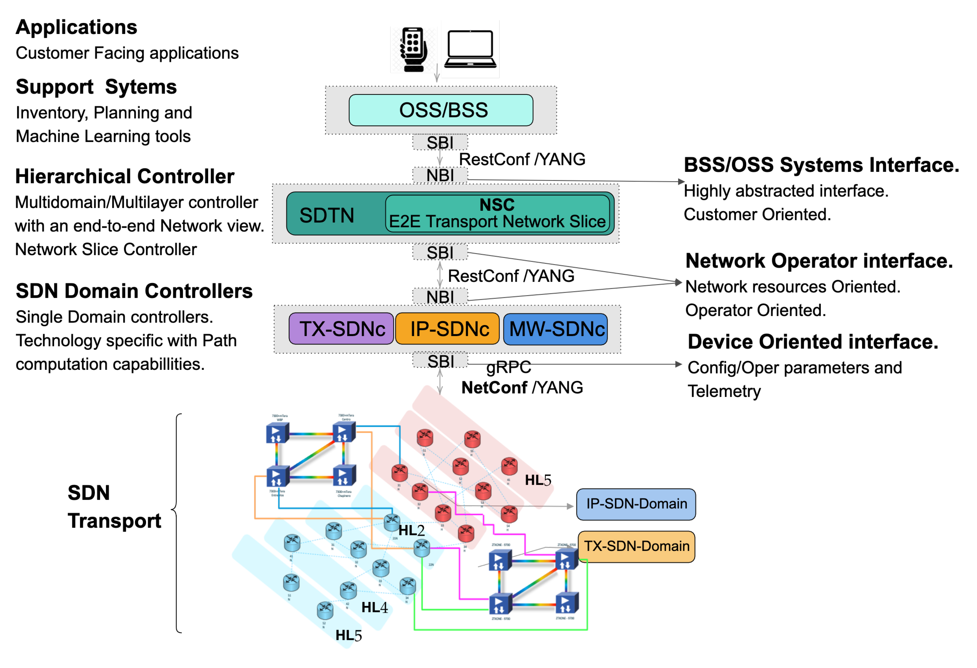
3. Proposed Architecture

The iFUSION architecture is an architecture defined by Telefonica to strengthen the network automation and programmability in a service provider environment, as depicted in Figure 1 [21]. iFUSION is a two-layer control architecture, with specific domain controllers per technological domain (IP/MPLS, microwave and optical) in the bottom and a Software-Defined Transport Network controller (SDTN controller) to handle the multi-layer and multi-domain transport network resources. The domain controllers directly communicate with the network elements and the SDTN controller with the OSS/BSS systems. More than the functional block definition, iFUSION includes the usage of: (1) Standard interfaces based on RESTCONF/YANG [22] for the communication between control components and NETCONF/YANG [23] to configure the network elements; (2) YANG data models based on latest releases in the standards-development organizations (SDOs): IETF, ONF and OpenConfig.
Figure 1 shows the network scheme of the iFUSION architecture in terms of components and relationships among them. The following sections define each of the structural pillars in the architecture, including its role in network slicing.

3.1. Software Defined Transport Network Controller

The Software-Defined Transport Network Controller is a functional block with the following purposes [21]; It is The main entry point from the OSS/BSS systems to the network. It is in charge of coordinating/providing services through several domains and layers. It has the multi-layer/multi-domain topological view of the network. The SDTN controller can split requirements based on the technological requirements. During this process, the SDTN controller can add/assign logical resources to be used by the network at the service implementation. The SDTN controller have two RESTCONF interfaces, one to process the OSS/BSS systems’ requirements and one to send the specific requests to the domain controllers. TeraFlow project [24] is proposing the development of a cloud-native SDN controller that will serve as SDTN.
The SDTN controller can have incorporated the Network Slice Controller as a working piece of its implementation.

3.2. Network Slice Controller

The Network Slice Controller (NSC) effectuates a transport network slice in the underlying transport infrastructure, manages and control the state of resources and topologies associated with it. The NSC receives a transport network slice request from the Operation Support System and Business Support System (OSS/BSS). The NSC runs an internal workflow for transport network slice life-cycle management and interacts with underlying IP and Optical Domain controllers via a RESTCONF client. As described in the following sections, depending on the NSC location in the architecture, the NSC will delegate to SDN Domain controllers to configure the network (Section 3.5 (a) and (b)) or make it directly through a NETCONF SBI (Section 3.5 (c)).
The network slice controller is the key building block for control and management of network slice. It provides the creation/modification/deletion, monitoring an optimization of network slices in a multi-domain, a multi-technology and multi-vendor environment. It has two main functionalities, defined in [25,26]:
  • Map: The NSC must map the Network Slice requests to the underlying technology-specific infrastructure. Accordingly, It maintains a record of the mapping from user requests to slice instantiations, as needed to allow for subsequent control functions like modification or deletion.
  • Realize: The NSC should realize the network slice request using its SBI interface against the domain controllers in either physical or logical connectivity through VPNs or various tunnelling technologies such as Segment Routing, MPLS, etc.

3.3. Network Domain Controller

The network domain controller (SDN Controller) is in charge of network elements (network domain). It has standard southbound interfaces to communicate with the network elements. The Domain controller SBI relies on using the Network configuration protocol (NETCONF) to interact with the underlying technology’s network elements. The SDN controller also has a northbound interface to communicate with the SDTN controller or the OSS/BSS Systems using RESTCONF.

3.4. Yang Models for Network Controllers

As described until now, the three control elements: SDTN controller, Network Slicing Controller and Network Domain controllers, has standard SBI and NBI interfaces to communicate between them and against the network or the OSS/BSS systems. The standard interfaces are composed of selecting a protocol to transfer the data and YANG data models to define how the message is formed. For that sense, the YANG modelling activities have acquired significant relevance across the standardization entities. This is to such an extent that by 2019, the number of correctly extracted YANG models from IETF drafts was 283, in the Broadband forum was 214, and in Openconfig was 137 [27]; similarly, other organizations like the MEF, 3GPP or ONF produced YANG data models to describe technologies, protocols or connectivity services as well. Thus, navigating through the massive set of YANGs available and selecting the suitable pack of data models to define each functional block’s interfaces becomes an essential task from the architectural definitions point of view.
To request and after instantiate the network slices a set of these data models are described as the experimental base of this work are described in the Table 2.

3.5. Instantiating of Network Slices in SDN Transport Networks

As described before in the Section 3.1, the OSS/BSS systems may request the deployment of a new network slices with certain transport characteristics. Each network slice must be isolated from any other network slices or different services delivered to particular customers and naturally, other network slices or services must not negatively impact the requested transport network slice’s delivery.
To provide this isolation and instantiate the slice in the network there are certain implementation options ranging from softer to hardest grades of isolation, as follows:
  • No-isolation, meaning that slices are not separated.
  • Logical-isolation, where slices are logically separated, only a certain degree of isolation is performed through QoS mechanisms.
  • Service-isolation, where virtual resources and NFs are shared.
  • Process-isolation, where slices include process and threads isolation.
  • Virtual-resource-isolation, where slices have dedicated virtual resources.
  • Network-functions-isolation, where Network Function (NF) are dedicated to a single network slice.
  • Physical-isolation, where slices are completely physically separated, for example, in different locations.
  • Physical-network-isolation, where slices contain physically separated links.
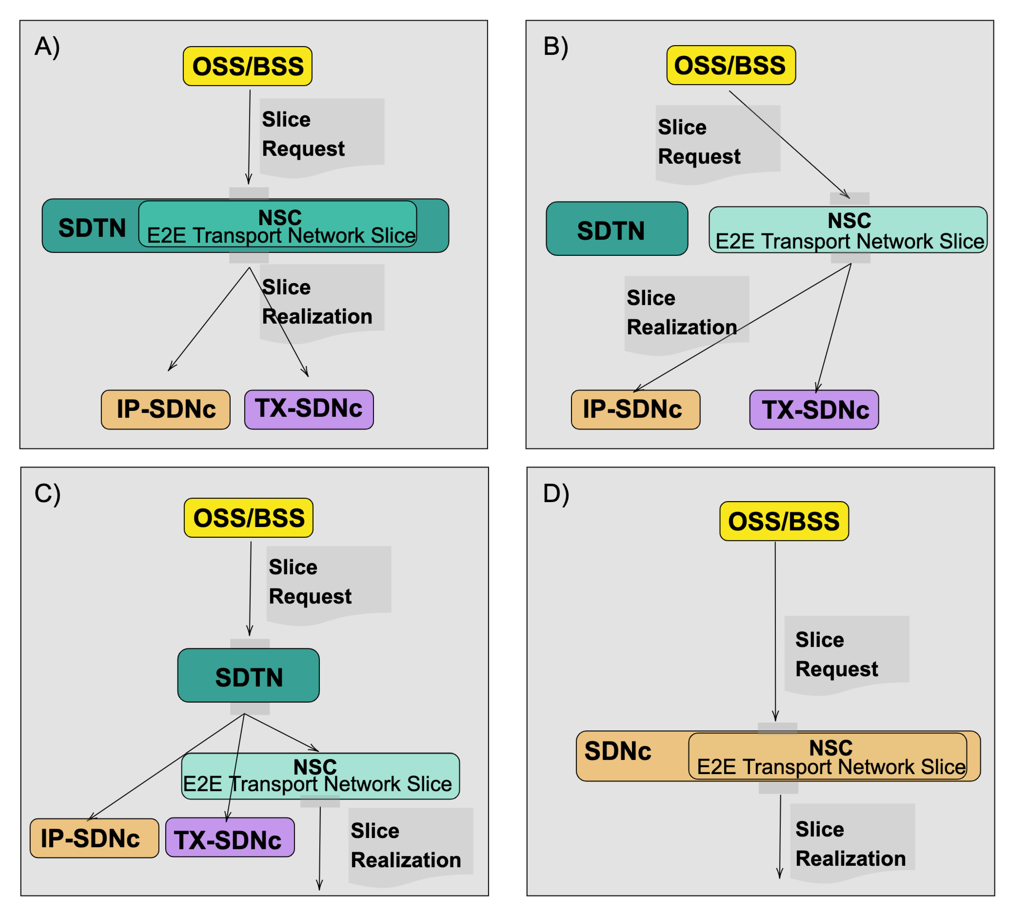
As the isolation grade is a significant constraint to consider for the network slice implementation, the selected network infrastructure and the control elements selected would generate different sets of capabilities in the Network Slice Controller. Figure 2 describes three of the possibilities analyzed from the point of view of the mapping and realization tasks of the Network Slice Controller:
(a)
Network Slice Controller as part of the hierarchical controller: When the Network Slice Controller is a Hierarchical SDN controller module, the NSC’s and the Hierarchical Network Controller should share the same internal data and the same NBI. Thus, to process the customer, view the H-SDN module must be able to:
  • Map: The customer request received using the must be processed by the NCS. The mapping process takes the network-slice SLAs selected by the customer to available Routing Policies and Forwarding policies.
  • Realize: Create necessary network requests. The slice’s realization can be translated into one or several LXNM Network requests, depending on the number of underlay controllers. Thus, the NCS must have a complete view of the network to map the orders and distribute them across domains. The realization should include the expansion/selection of Forwarding Policies, Routing Policies, VPN policies and Underlay transport preference.
To maintain the data coherence between the control layers, the network-slice-id used must be directly mapped to the transport-instance-id at the VPN-Node level.
(b)
Network Slice Controller as an stand-alone controller:
When the Network Slice Controller is a stand-alone controller module, the NSC’s should perform the same two tasks described before:
  • Map: Process the customer request. The customer request can be sent using the [draft-liu-teas-transport-network-slice-yang-01]. This draft allows the topology mapping of the Slice request.
  • Realize: Create necessary network requests. The slice’s realization will be translated into one LXNM Network request. As the NCS has a topological view of the network, the realization can include the customer’s traffic engineering transport preferences and policies.
(c)
Network Slice Controller at the domain controller level:
The Network Slice Controller can at the same level as the network domain controllers. The SDTN controller should handle the slices request, and the realization can be done by the NSC directly communicating with the Network Elements. The SDTN controller should create unified network views, including each transport domain and the network slices.
  • Map: The SDTN would Process the customer request. The customer request can be sent using the [draft-liu-teas-transport-network-slice-yang-01]. This draft allows the topology mapping of the Slice request.
  • Realize: The realization can be done by the NCS controller applying the service logic to create policies directly on the Network elements. The SDTN should handle the shared resources management between domains.
(d)
Network Slice Controller as part of the domain controller:
When the Network Slice Controller is part of the domain controller, the OSS/BSS systems process the Slices requests and introduce the network abstraction layer. At the network level, the same device data model would be used in the NBI and SBI of the SDN controller. The direct translation would reduce the service logic implemented at the SDN controller level, grouping the mapping and translation into a single task:
  • Map & Realize:The mapping and realization can be done by the Domain controller applying the service logic to create policies directly on the Network elements.

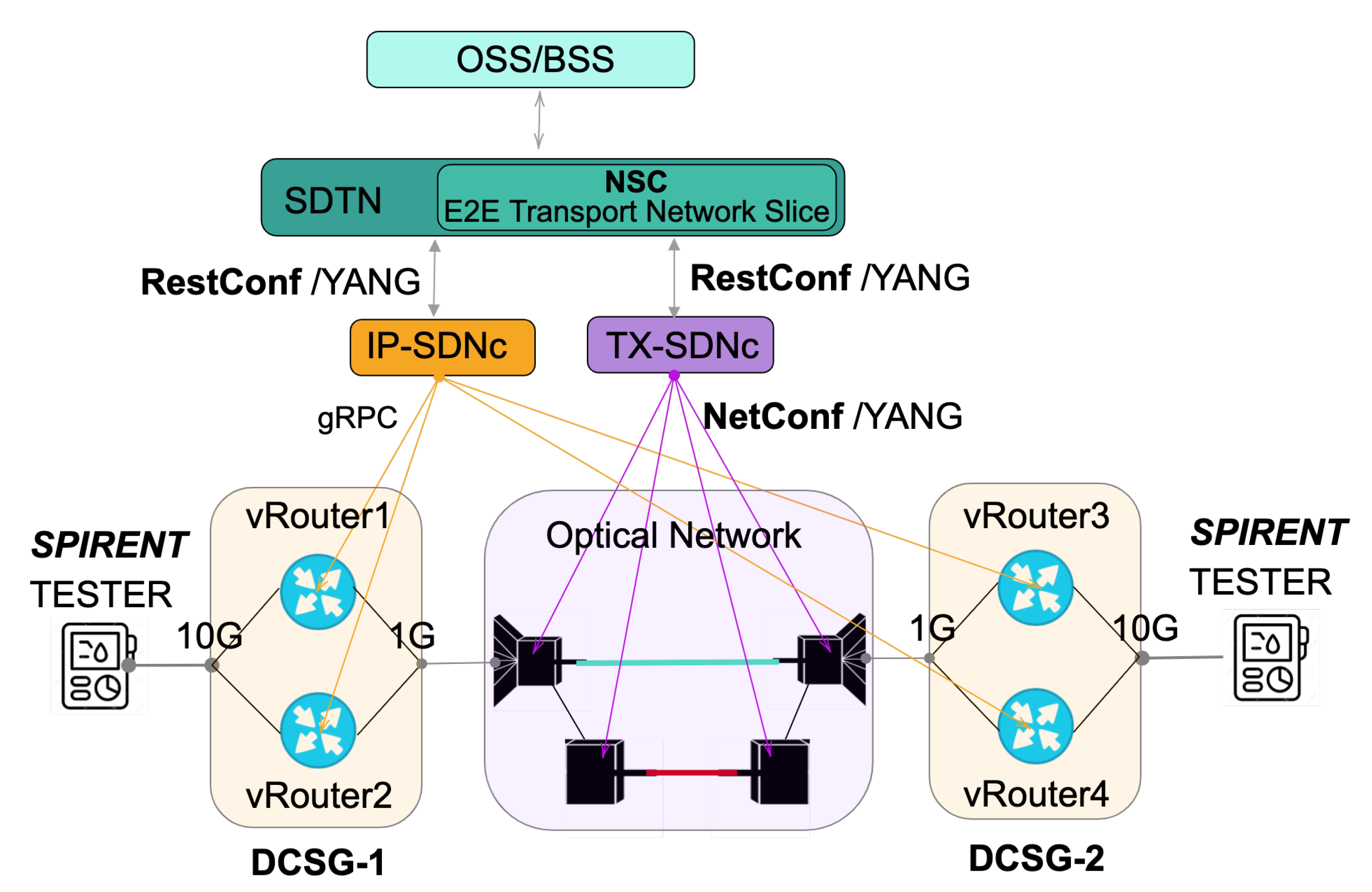
4. Experimental Validation

The experimental testbed has been distributed between Telefónica and CTTC laboratory premises, as depicted in Figure 3. The testbed includes two layers, a control layer and a transport layer.
Telefonica and CTTC deployed a control layer composed of three relevant items. First, to receive all the service requests, a Network Slice Controller was developed as part of the SDTN controller. Second, to interact with the transport domains, the testbed included Two (2) controllers, one for IP and one for Optical. To configure the routers, the IP SDN Controller used gRPC, while the Optical SDN controller used Netconf with T-API for the configuration tasks.
The physical transport layer was composed of:
  • Two (2) 7316 Edgecore switches running ONIE.
  • Two (2) Spirent traffic generator.
  • Four (4) Flexi-grid DWDM nodes.
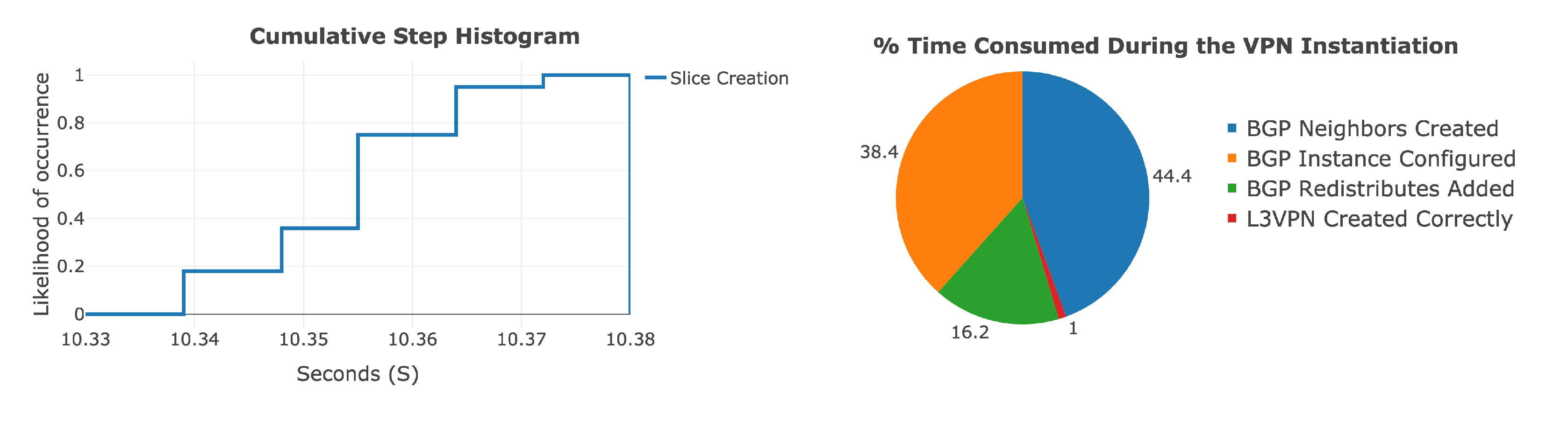
The Edgecore used a 10 Gigabit Ethernet (10G) interface for the connection against the Spirent testers and 1G interfaces to the Optical devices. Furthermore, on each Edgecore, two (2) separate virtual routers were configured to test redundancy and route filtering between the ends. The Network Operating system (NOS) running on the virtual-routers were volta-stack deployment version 20.4-2-36-g0ba8807.
As we have described previously, there are several requirements for network automation for network slicing. However, a service provider can not all treat all the needs in the same way. Thus, a set of use cases were designed and executed as part of the whole testing process, the use cases were the following:
1.
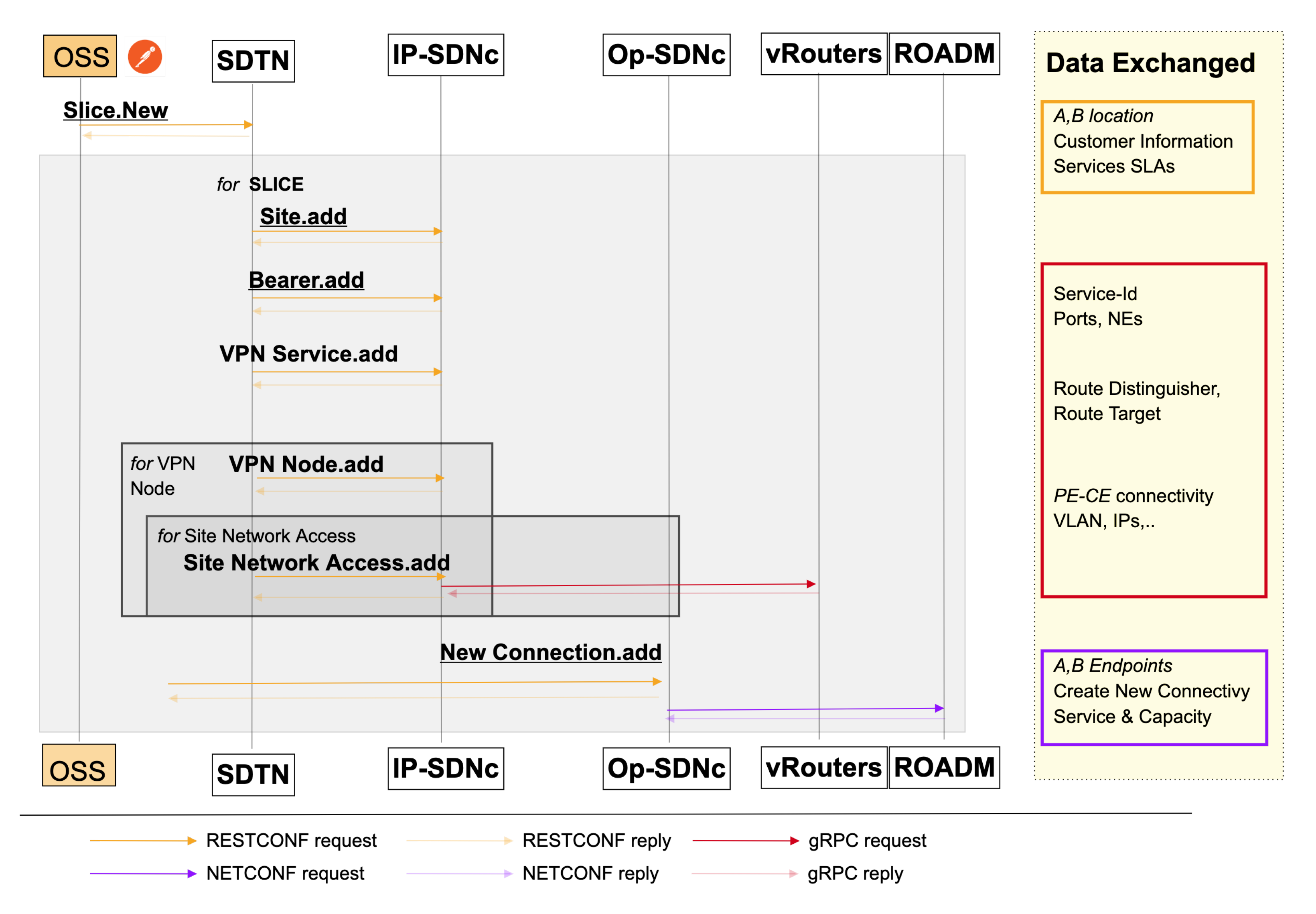
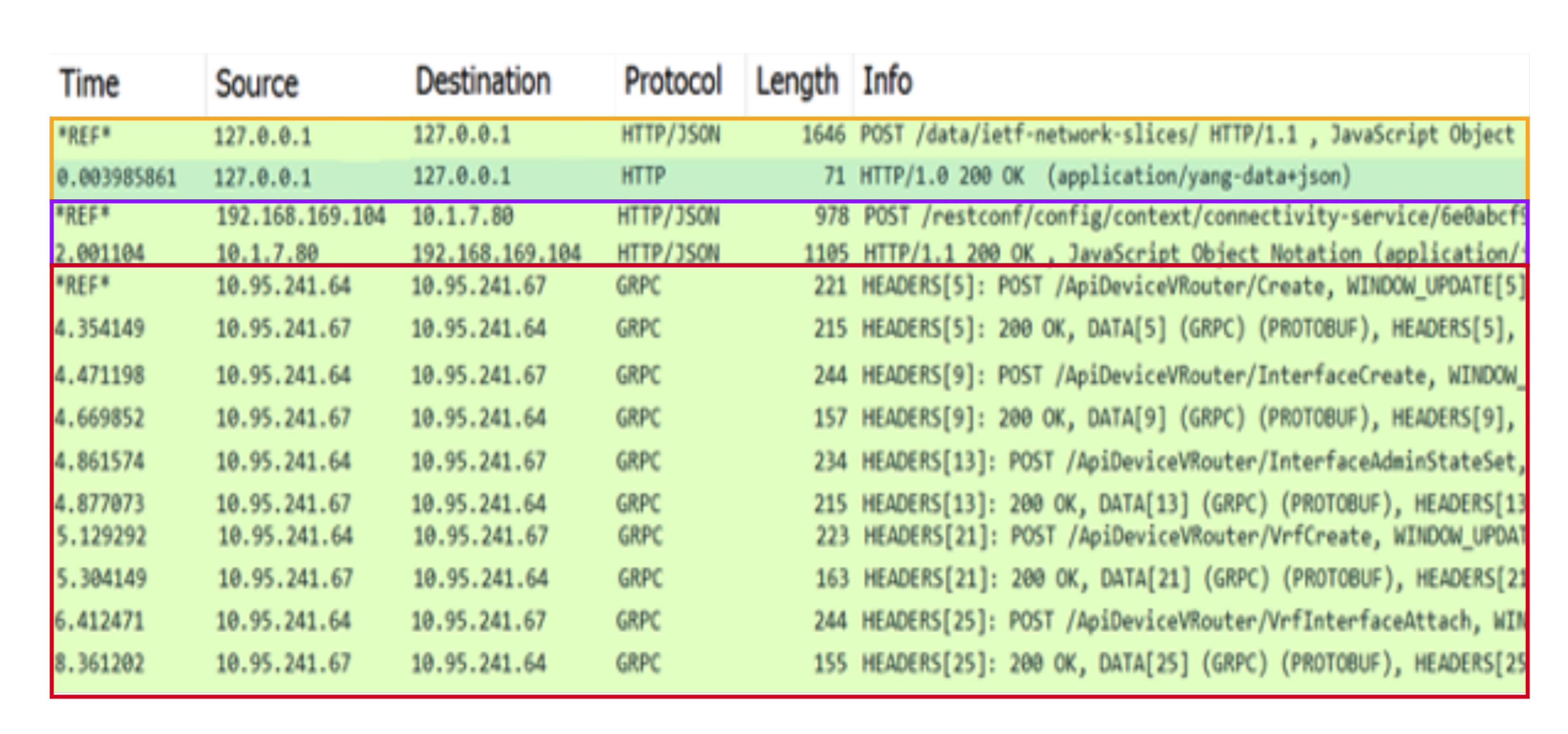
Slice Creation: To request a Standards-Based and Model-Driven isolated Network Slices using. The SDTN controller would receive and translate the network slice service into specific per domain requests as follows:
(a)
L3VPN service creation: In this use case, each network slice request requires an L3VPN service creation; thus, each L3VPN service would map to a single network slice. The endpoints defined in the slice request would map to Virtual Router and Forwarding (VRFs) instances on the virtual routers. The Yang data model used for the SDTN requests the L3VPN services to the IP domain controller was the L3NM [4].
(b)
DWDM connectivity: The T-API [5] was used to create a new connectivity service in the transport network to enable the L2-L1 communication between the network slice endpoints.
2.
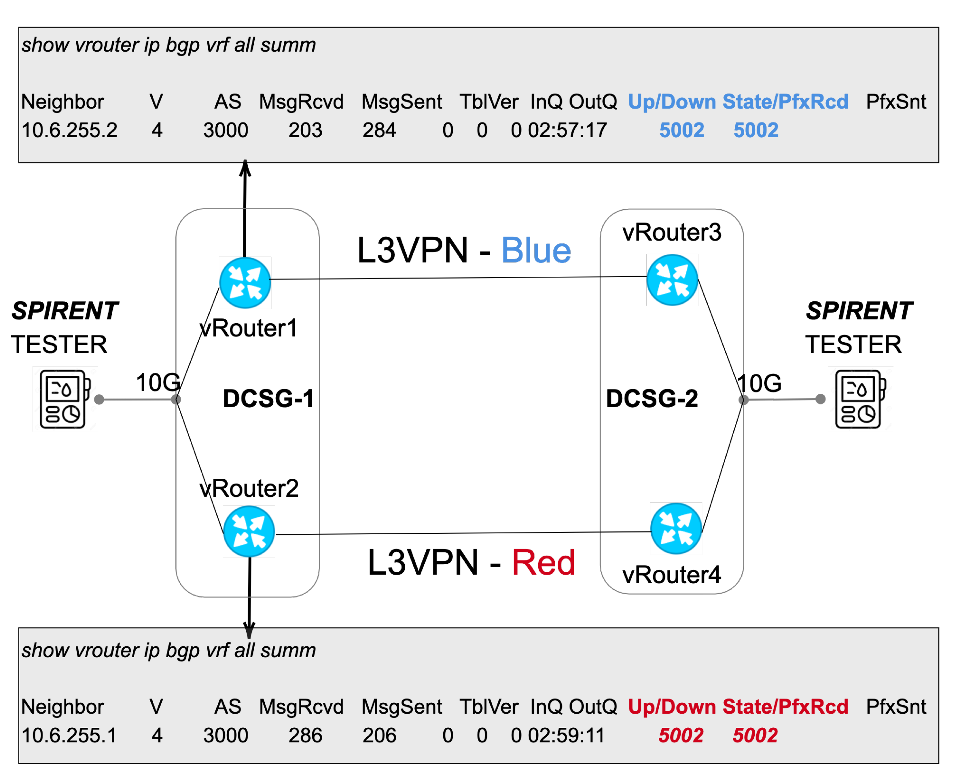
Add Prefixes and destroy: The second use case expects to validate the IP connectivity between the network slices. Hence the Spirent testers announced a set of 5k IP prefixes through the prior created network slices. Afterwards, the testers make an automatic IP reachability test and a CLI route redistribution validation. Once the route propagation was validated, the testing team stopped all the Spirent prefixes’ announcement, and a new automatic connectivity test was done.
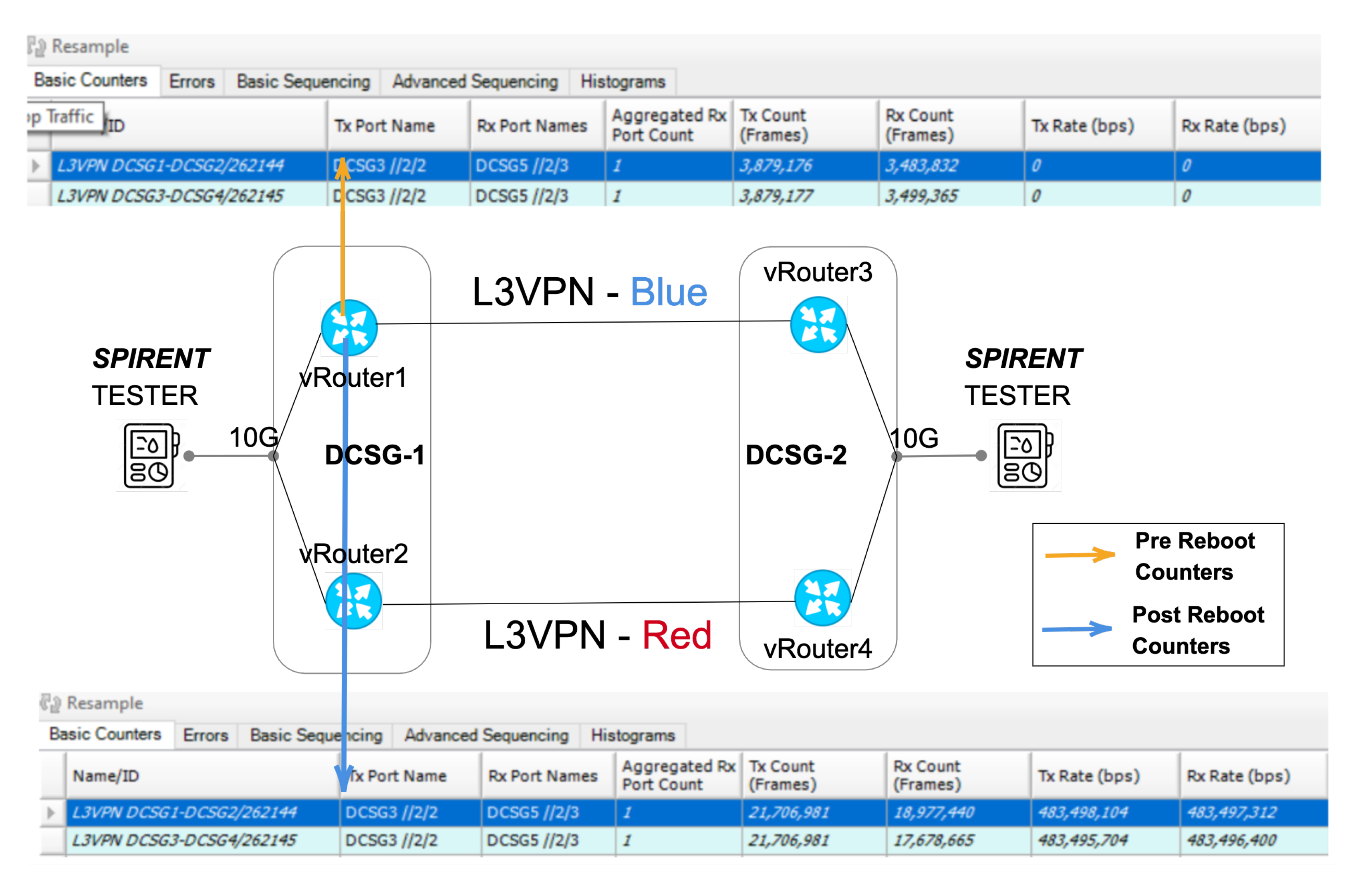
3.
Device recovery test: The third use case was to verify the network slices service continuity so. The testing team manually rebooted all the DCSGs. Once the devices got online again, we have checked the service status with a measurement of the service restoration time.

4.1. Slice Creation

The iFusion architecture enhancement proposed for this paper performs the management of services and resources through the use of information models that capture the definitions of managed entities in terms of attributes and supported operations. Hence, a set of Yang Data models has been defined to render and realize a network slice between each of the control entities. The workflow proposed used postman to simulate, the network slice creation requests. The YANG data-model used for this request was defined in [37]. It includes the endpoints, the customer information and the service level agreement of the slice requests. The PE-CE and the end-to-end connectivity protocols for the network slice realization was automatically expanded by the SDTN controller and received by the IP SDN controller to properly configure the network elements. Each network slice, The workflow can be seen in the Figure 4.
A capture of the messages exchanged between the control items is depicted in Figure 5. The Figure illustrates in Orange the messages exchanged for the Network Slice Creation using the IETF network slices data model. The subsequent statements show how the SDTN controller unwrapped the creation request message to the optical and IP domains. It illustrates in red the IP network massages using gRPC, including the access ports, routing protocols, and PE-CE connectivity parameters. In purple, the T-API messages have the connectivity and optical service requirements.
The time consumed in the Slices creation was 10.34 s on average. The left part of the Figure 6 depicts a cumulative histogram of the time consumed for the slice creation in the controller layer using ten samples. Additionally, the rigth side Figure 6 shows the percentage of time spent for the VPN-instantiation in the Virtual routers. The most time-consuming task is the BGP Neighbours creation (13 s), followed by the BGP instance redistribution (10 s). In contrast, the device implemented the primary VPN configuration parameters (Rute-Distinghuiser, Route Target and Router ID) in less than a second.

4.2. Add Prefixes and Destroy

Once the domain controller realized the network slices, and we have validated the service status. The next step vas to verify the correct establishment of the data-plane sessions. Thus, the Spirent testers added 5k prefixes to each of the services(VRF-Blue and VRF-Red). To confirm the status of each service, we have captured the virtual routers BGP information, as depicted in Figure 7, where each VRF has 5002 prefixes received (PfxRcd).
After the end-to-end service creation and control and data plane validation, we have rebooted the devices to validate the service continuity after a simulated power failure. We validate that after the recovery was complete, all the traffic flows again between the network slices. To confirm the status of each device, we have captured the counters before and after the reboot process Figure 8. Each instance recovered sequentially, and it took up to 4.6 min for the latest service to completely restore the traffic flow.

5. Conclusions

Dealing with the necessity of a dynamic network resources allocation to provide a new generation of customer-tailored applications is a primary concern nowadays. In that sense, Telecom providers have to prepare their whole set of systems and network infrastructure to allow the introduction of end-to-end network automation. In that sense, this paper uses and validates the iFusion architecture defined by Telefonica, which is ready to support new use cases derived from the 5G adoption and transport network slices. Additionally, this work validates an end-to-end creation, modification and deletion of transport network slices with several degrees of isolation. Furthermore, the results indicate the feasibility of deploying multi-layer IP over DWDM transport network slices based on virtual routers and disjoint optical paths. Future work testing the map and realization of network slices in the different NSC controller positions is required. This testing would allow us to fully understand the information exchanged/stored in each layer to make feasible the deployments in real networks.

Author Contributions

Conceptualization, V.L.A., L.M.C.M., O.G.d.D. and R.V.; Data curation, J.-M.P.; Investigation, S.B. and R.V.; Software, D.G.-P. and X.L. Supervision, O.G.d.D., C.M., P.A., R.C., R.M. (Ricardo Martinez), J.P.F.-P. and R.M. (Raul Muñoz); Writing–original draft, S.B. and A.A.A.; Writing–review & editing, S.B., V.L.A., L.M.C.M., J.-M.P. and R.V. All authors have read and agreed to the published version of the manuscript.

Funding

This research was partially supported by the EC H2020 TeraFlow (101015857) and SpanishAURORAS (RTI2018-099178-I00).

Institutional Review Board Statement

Not applicable.

Informed Consent Statement

Not applicable.

Data Availability Statement

Not applicable.

Acknowledgments

Work partially supported by the EC H2020 TeraFlow (101015857) and Spanish AURORAS (RTI2018-099178-I00).

Conflicts of Interest

The authors declare no conflict of interest.

Abbreviations

3GPP3rd Generation Partnership Project
APIApplication programming interface
BSSBusiness Support System
BGPBorder Gateway Protocol
CECustomer Edge
IETFInternet Engineering Task Force
eMBBEnhanced Mobile Broadband
L2SML2VPN Service Model
L2NML2VPN Network Model
L3SML3VPN Service Model
L3NML3VPN Network Model
L3VPNLayer Three Virtual Private Network
MCMobile Core
mMTCMassive Machine Type Communication
MPLSMultiprotocol Label Switching
NASSNetwork As A Service
NGMNNext Generation Mobile Networks
NSINetwork Slice Instance
ODUOptical Distribution Unit
ONFOpen Networking Foundation
OSSOperation Support Systems
PEProvider Edge
QoSQuality of service
RANRadio Access Network
SDNSoftware Defined Network
SIService Instance
URLLCUltra Reliable Low Latency Communications
VSIVirtual switching Interfaces
VPNVirtual Private Network
VRFVirtual Routing and Forwarding
YANGYet Another Next Generation

References

  1. Ordonez-Lucena, J.; Ameigeiras, P.; Lopez, D.; Ramos-Munoz, J.J.; Lorca, J.; Folgueira, J. Network slicing for 5G with SDN/NFV: Concepts, architectures, and challenges. IEEE Commun. Mag. 2017, 55, 80–87. [Google Scholar] [CrossRef] [Green Version]
  2. Contreras, L.M.; López, D.R. A Network Service Provider Perspective on Network Slicing. IEEE Softwarization: A Collection of Short Technical Articles. 2018. Available online: https://sdn.ieee.org/newsletter/january-2018/a-network-service-provider-perspective-on-network-slicing?highlight=WyJhIiwiJ2EiLCJuZXR3b3JrIiwibmV0d29yaydzIiwiJ25ldHdvcmsiLCJzZXJ2aWNlIiwic2VydmljZScsIiwiJ3NlcnZpY2UiLCJwcm92aWRlciIsInByb3ZpZGVyJ3MiLCJhIG5ldHdvcmsiLCJhIG5ldHdvcmsgc2VydmljZSIsIm5ldHdvcmsgc2VydmljZSIsIm5ldHdvcmsgc2VydmljZSBwcm92aWRlciIsInNlcnZpY2UgcHJvdmlkZXIiXQ== (accessed on 1 July 2021).
  3. Barguil, S.; de Dios, O.G.; Boucadair, M.; Munoz, L.; Jalil, L.; Ma, J. A Layer 2 VPN Network Yang Model. draft-ietf-opsawg-l2nm-02. Available online: https://datatracker.ietf.org/doc/html/draft-ietf-opsawg-l2nm-02 (accessed on 1 July 2021).
  4. Barguil, S.; de Dios, O.G.; Boucadair, M.; Munoz, L.; Aguado, A. A Layer 3 VPN Network YANG Model. draft-ietf-opsawg-l3sm-l3nm-05. Available online: https://datatracker.ietf.org/doc/html/draft-ietf-opsawg-l3sm-l3nm (accessed on 1 July 2021).
  5. Vilalta, R.; Muñoz, R.; Landi, G.; Rodriguez, L.; Capitani, M.; Casellas, R.; Martínez, R. Experimental Demonstration of the BlueSPACE’s NFV MANO Framework for the Control of SDM/WDM-enabled Fronthaul and Packet-based Transport Networks by Extending the TAPI. In Proceedings of the IEEE 2018 European Conference on Optical Communication (ECOC), Rome, Italy, 23–27 September 2018; pp. 1–3. [Google Scholar]
  6. Shaikh, A. OpenConfig-progress toward vendor-neutral network management. In Proceedings of the North American Network Operators’ Group (NANOG) 71, San Jose, CA, USA, 2–4 October 2017. [Google Scholar]
  7. Alcalá, A.; Barguil, S.; López, V.; Contreras, L.M.; Manso, C.; Alemany, P.; Casellas, R.; Martínez, R.; Gonzalez-Perez, D.; Liu, X.; et al. Multi-layer Transport Network Slicing with Hard and Soft Isolation. In Proceedings of the 2021 Optical Fiber Conference (OFC), Virtual Event, 6–11 June 2021. [Google Scholar]
  8. Alliance, N. Description of network slicing concept. NGMN 5G P 2016. Available online: https://www.ngmn.org/publications/description-of-network-slicing-concept.html (accessed on 1 July 2021).
  9. Kukliński, S.; Tomaszewski, L. Business models of network slicing. In Proceedings of the 2018 9th International Conference on the Network of the Future (NOF), Poznan, Poland, 19–21 November 2018; pp. 19–21. [Google Scholar]
  10. Zhang, N.; Liu, Y.F.; Farmanbar, H.; Chang, T.H.; Hong, M.; Luo, Z.Q. Network slicing for service-oriented networks under resource constraints. IEEE J. Sel. Areas Commun. 2017, 35, 2512–2521. [Google Scholar] [CrossRef] [Green Version]
  11. Khan, L.U.; Yaqoob, I.; Tran, N.H.; Han, Z.; Hong, C.S. Network slicing: Recent advances, taxonomy, requirements, and open research challenges. IEEE Access 2020, 8, 36009–36028. [Google Scholar] [CrossRef]
  12. Foukas, X.; Patounas, G.; Elmokashfi, A.; Marina, M.K. Network slicing in 5G: Survey and challenges. IEEE Commun. Mag. 2017, 55, 94–100. [Google Scholar] [CrossRef] [Green Version]
  13. Huang, S.; Guo, B.; Liu, Y. 5G-Oriented optical underlay network slicing technology and challenges. IEEE Commun. Mag. 2020, 58, 13–19. [Google Scholar] [CrossRef]
  14. Rosen, E.; Rekhter, Y. BGP/MPLS IP Virtual Private Networks (VPNs). RFC 4364. Available online: https://www.rfc-editor.org/info/rfc8049 (accessed on 1 July 2021). [CrossRef] [Green Version]
  15. Litkowski, S.; Tomotaki, L.; Ogaki, K. YANG Data Model for L3VPN Service Delivery. RFC 8049. Available online: https://www.rfc-editor.org/info/rfc4364 (accessed on 1 July 2021). [CrossRef] [Green Version]
  16. Marotta, A.; Cassioli, D.; Tornatore, M.; Hirota, Y.; Awaji, Y.; Mukherjee, B. Reliable slicing with isolation in optical metro-aggregation networks. In Proceedings of the IEEE 2020 Optical Fiber Communications Conference and Exhibition (OFC), San Diego, CA, USA, 8–12 March 2020; pp. 1–3. [Google Scholar]
  17. Contreras, L.M.; Barguil, S.; Vilalta, R.; López, V. Architecture for integrating vertical customer’s programmability control of network functions and connectivity in a slice-as-a-service schema. EURASIP J. Wirel. Commun. Netw. 2021, 2021, 1–16. [Google Scholar] [CrossRef]
  18. 3GPP TS 23.501. System Architecture for the 5G System (3GPP TS 23.501 Version 15.3. 0 Release 15), September 2018. Available online: https://www.etsi.org/deliver/etsi_ts/123500_123599/123501/15.03.00_60/ts_123501v150300p.pdf (accessed on 1 July 2021).
  19. Redana, S.; Bulakci, Ö.; Zafeiropoulos, A.; Gavras, A.; Tzanakaki, A.; Albanese, A.; Kousaridas, A.; Weit, A.; Sayadi, B.; Jou, B.T.; et al. 5G PPP Architecture Working Group: View on 5G Architecture. 2019. Available online: https://bura.brunel.ac.uk/bitstream/2438/18546/1/FullText.pdf (accessed on 1 July 2021).
  20. Ferrús, R.; Sallent, O.; Pérez-Romero, J.; Agusti, R. On the automation of RAN slicing provisioning and cell planning in NG-RAN. In Proceedings of the IEEE 2018 European Conference on Networks and Communications (EuCNC), Ljubljana, Slovenia, 18–21 June 2018; pp. 37–42. [Google Scholar]
  21. Contreras, L.; González, Ó.; López, V.; Fernández-Palacios, J.; Folgueira, J. iFUSION: Standards-based SDN Architecture for Carrier Transport Network. In Proceedings of the 2019 IEEE Conference on Standards for Communications and Networking (CSCN), Granada, Spain, 28–30 October 2019; pp. 1–7. [Google Scholar]
  22. Bierman, A.; Bjorklund, M.; Watsen, K. RESTCONF protocol. RFC 8040. Available online: https://www.rfc-editor.org/info/rfc8040 (accessed on 1 July 2021). [CrossRef]
  23. Enns, R.; Bjorklund, M.; Schoenwaelder, J.; Bierman, A. Network configuration protocol (NETCONF). RFC 6241. Available online: https://www.rfc-editor.org/info/rfc6241 (accessed on 1 July 2021). [CrossRef] [Green Version]
  24. Vilalta, R.; Muñoz, R.; Casellas, R.; Martínez, R.; López, V.; González-de-Dios, O.; Pastor, A.; Katsikas, G.; Klaedtke, F.; Monti, P.; et al. TeraFlow: Secured Autonomic Traffic Management for a Tera of SDN Flows. In Proceedings of the IEEE 2021 European Conference on Networks and Communications (EuCNC), Virtual Event, 8–11 June 2021. [Google Scholar]
  25. Rokui, R.; Homma, S.; Makhijani, K.; Contreras, L.; Tantsura, J. Definition of IETF Network Slices. draft-ietf-teas-ietf-network-slice-definition-01. Available online: https://datatracker.ietf.org/doc/html/draft-ietf-teas-ietf-network-slice-definition (accessed on 1 July 2021).
  26. Gray, E.; Drake, J. Framework for IETF Network Slices. draft-ietf-teas-ietf-network-slice-framework-00. Available online: https://datatracker.ietf.org/doc/html/draft-ietf-teas-ietf-network-slice-framework (accessed on 1 July 2021).
  27. Available online: http://www.claise.be/YANGPageMain.html (accessed on 3 April 2021).
  28. Wen, B.; Fioccola, G.; Xie, C.; Jalil, L. A YANG data model for layer 2 virtual private network (L2VPN) service delivery. RFC 8466. Available online: https://www.rfc-editor.org/info/rfc8466 (accessed on 1 July 2021). [CrossRef]
  29. Saad, T.; Gandhi, R.; Liu, X.; Beeram, V.; Bryskin, I. A YANG Data Model for Traffic Engineering Tunnels, Label Switched Paths and Interfaces. draft-ietf-teas-yang-te-25. Available online: https://datatracker.ietf.org/doc/html/draft-ietf-teas-yang-te-25 (accessed on 1 July 2021).
  30. Liu, X.; Bryskin, I.; Beeram, V.; Saad, T.; Shah, H.; de Dios, O.G. YANG Data Model for Traffic Engineering (TE) Topologies. RFC 8795. Available online: https://www.rfc-editor.org/info/rfc8795 (accessed on 1 July 2021). [CrossRef]
  31. Liu, X.; Bryskin, I.; Beeram, V.; Saad, T.; Shah, H.; de Dios, O.G. YANG Data Model for Traffic Engineering (TE) Topologies. draft-ietf-teas-yang-l3-te-topo-10. Available online: https://datatracker.ietf.org/doc/html/draft-ietf-teas-yang-l3-te-topo (accessed on 1 July 2021).
  32. Lee, Y.; Dhody, D.; Fioccola, G.; Wu, Q. Traffic Engineering (TE) and Service Mapping Yang Model. draft-ietf-teas-te-service-mapping-yang-07. Available online: https://datatracker.ietf.org/doc/html/draft-ietf-teas-te-service-mapping-yang-07 (accessed on 1 July 2021).
  33. Jethanandani, M.; Agarwal, S. YANG Data Model for Network Access Control Lists (ACLs). RFC 8519. Available online: https://www.rfc-editor.org/info/rfc8519 (accessed on 1 July 2021). [CrossRef]
  34. Qu, Y.; Tantsura, J.; Lindem, A.; Liu, X. A YANG Data Model for Routing Policy. draft-ietf-rtgwg-policy-model-27. Available online: https://datatracker.ietf.org/doc/html/draft-ietf-rtgwg-policy-model-27 (accessed on 1 July 2021).
  35. Jethanandani, M.; Patel, K.; Hares, S.; Haas, J. BGP YANG Model for Service Provider Networks. draft-ietf-idr-bgp-model-10. Available online: https://datatracker.ietf.org/doc/html/draft-ietf-idr-bgp-model-10 (accessed on 1 July 2021).
  36. Zheng, H.; Busi, I.; Guo, A.; Lopez, V. Framework and Data Model for OTN Network Slicing. draft-zheng-ccamp-yang-otn-slicing-01. Available online: https://datatracker.ietf.org/doc/html/draft-zheng-ccamp-yang-otn-slicing-01 (accessed on 1 July 2021).
  37. Liu, X.; Tantsura, J.; Bryskin, I.; Contreras, L.; Wu, Q.; Belotti, S.; Rokui, R. IETF Network Slice YANG Data Model. draft-liu-teas-transport-network-slice-yang-02. Available online: https://datatracker.ietf.org/doc/html/draft-liu-teas-transport-network-slice-yang-02 (accessed on 1 July 2021).
Figure 1. Overall proposed architecture.
Applsci 11 06219 g001
Figure 2. Possible Network Slice instantation in a service provider network. (A) Network Slice Controller as part of the hierarchical controller, (B) Network Slice Controller as an independent hierarchical controller, (C) Network Slice Controller as an independent domain controller and (D) Network Slice Controller as part of the domain controller.
Applsci 11 06219 g002
Figure 3. Network Design, including the Logical and Physical Infrastructure to support the test cases.
Applsci 11 06219 g003
Figure 4. Workflow used to instantiate the network slices in the network. From Postman, a user sends a slice request to the SDTN controller. The SDTN controller automatically split the request based on technological requirements. The L3NM and the T-API are used for the IP and Optical domains, respectively.
Applsci 11 06219 g004
Figure 5. Capture of the workflow used to instantiate the network slices in the network (Orange). The capture shows the IP network configuration (Red) and the T-API Optical domains (Purple).
Applsci 11 06219 g005
Figure 6. A cumulative step histogram of the time consumed for the slice creation, and the time consumed in during the VPN instantiation in the vRoutes.
Applsci 11 06219 g006
Figure 7. Comparison of the Prefixes received and Sent in each of the network slices deployed in the network. Each Network slice (Blue and Red) has 5K prefixes announced.
Applsci 11 06219 g007
Figure 8. Depicts comparing the counters in the network slice Blue, prior (Up) and after (Down) the device reboot. Once the devices are down, the counters go down to zero; after 4.6 min and once the device is ready, the counters move up again.
Applsci 11 06219 g008
Table 1. Possible Applications derived from the 5G implementations.
ApplicationsDefinitionExample
Ultra Reliable Low
Latency Communications
(uRLLC)
Requires support for 1 ms
latencies, 0.001% packet loss,
user mobility up to 100 km/h
Autonomous driving or
Industrial automation
Massive Machine
Type Communications
(mMTC)
Requires support for 1 million
devices per square kilometer,
tens of bps bandwidth,
and latency minimization
for battery life optimization
Massive IoT
Enhanced Mobile
Broadband (eMBB)
Requires Gbps bandwidth,
real time or not
Immersive UIs based
Augmented Reality
Virtual Reality. Streaming
of High Quality Video
Table 2. Set of these data models are described as the experimental base of this work.
ModelsDescriptionExample
LxVPNThese models describe a VPN service from the
customer or network operator point of view.
L3SM: [15]
L2SM: [28]
L3NM: [4]
L2SM: [3]
Traffic EngineeringThese models allow to manipulate
Traffic Engineering tunnels within the network
segment. Technology-specific extensions allow to work
with a desired technology (e.g., MPLS RSVP-TE tunnels,
Segment Routing paths, OTN tunnels, etc.)
TE: [29]
TE Topology: [30,31]
TE Service Mapping
extensions
These extensions allow to specify for LxVPN the
details of an underlay based on Traffic Engineering
Service Mapping: [32]
ACLs and
Routing policies
Even though ACLs and routing policies are device models,
It’s exposure in the NBI of a domain controller allows to
provide an additional granularity that the network
domain controller is not able to infer on its own.
ACL: [33]
Routing Policy: [34,35]
OTNAs a part of the transport network, OTN can provide
hard pipes with guaranteed data isolation and
deterministic low latency, which are highly demanded
in the Service Level Agreement (SLA).
OTN Slice: [36]
SlicingSet of data models available to map
and realize the network Slices.
Network Slice NBI: [25,26]
Publisher’s Note: MDPI stays neutral with regard to jurisdictional claims in published maps and institutional affiliations.

