Abstract
In recent years, collaborative robots have become one of the main drivers of Industry 4.0. Compared to industrial robots, automated guided vehicles (AGVs) are more productive, flexible, versatile, and safer. They are used in the smart factory to transport goods. Today, many producers and developers of industrial robots have entered the AGV sector. However, they face several challenges in designing AGV systems, such as the complexity and discontinuity of the design process, as well as the difficulty of defining a decentralized system decision. In this paper, we propose a new integrated design methodology based on swarm robotics to address the challenges of functional, physical, and software integration. This methodology includes two phases: a top-down phase from requirements specification to functional and structural modeling using the systems modeling language (SysML); with a bottom-up phase for model integration and implementation in the robot operating system (ROS). A case study of an automated guided vehicle (AGV) system was chosen to validate our design methodology and illustrate its contributions to the efficient design of AGVs. The novelty of this proposed methodology is the combination of SysML and ROS to address traceability management between the different design levels of AGV systems, in order to achieve functional, physical and software integration.
1. Introduction
Rapid advancements in manufacturing technologies and applications in industries increase productivity. Today’s industry needs the digitization and intelligence of manufacturing processes [1]. Industry 4.0 represents the fourth industrial revolution which is defined as a new level of organization and control over the entire value chain of the product life cycle; it is oriented towards customer requirements. Industry 4.0 is a realistic concept that includes the industrial internet, the internet of things, smart manufacturing, and cloud-based manufacturing [2].
The six main principles of Industry 4.0 are: interconnection and interoperability, information transparency (e.g., virtualization), decentralization and autonomous decisions, real-time capability, technical support and service orientation, and finally modularity [3]. In fact, the IoT provides system connectivity. Thus, it is essential to establish horizontal and vertical integration. Additionally, information transparency means that all objects, processes, and systems are transformed into virtual objects that enable simulation and optimization of all processes. In addition, decentralization and autonomy mean placing AI in each tool and allowing independence in decision-making based on information available in the cloud. Real-time operation implies the ability to make changes to production at any time. By connecting systems and giving them autonomy to make decisions, they become capable of reacting instantly when a problem arises. Similarly, technical support represents the connection between the product and the production system after the product is in operation. Finally, modularity offers the possibility to change parts of a product during production according to the customer’s wishes [4].
Collaborative robotics has been considered as one of the enabling technologies of the fourth industrial revolution, within the framework of the Industry 4.0 program [5]. The introduction of such robotic systems in industrial applications poses several problems which cannot be ignored. Nowadays, the use of AGVs in factory logistics is not yet widespread in manufacturing plants. The transport of raw materials and final products is still done by manual forklifts [6]. For this reason, many manufacturers and developers of industrial robots have entered the AGV industry to reduce these problems. However, it is necessary to point out the main obstacles that discourage the industrial sector from integrating AGV systems into their production lines today.
The first obstacle is related to communication. In general, AGV systems use wireless communication technology to exchange information between mobile robots, the AGV management system, the fleet management system, and other external elements. This means that everything depends on the quality and robustness of the WiFi connection. However, with the advent of 5G technology, connectivity will theoretically be 10 times higher, and thus 5G will promote the interconnection of all existing networks and technologies, and allow them to communicate with each other more effectively. The second barrier to AGV integration in the industry and particularly smart factories is the problem of making AGVs built by different manufacturers work together. Indeed, different AGV systems do not really speak the same language. We will see later in this paper that the right choice of AGV development methodology and tools could facilitate the collaboration of AGV systems from different manufacturers.
The third barrier to AGV integration is related to the limited flexibility of AGVs compared to driver-controlled vehicles. A human operator can react and change his task rapidly. Thus, AGVs are less suitable for non-repetitive tasks. However, if the tasks are repetitive, the choice of the AGV solution could be justified, and this can improve workplace safety. The fourth barrier to integrating AGVs into the production industry is related to the restrictions of the operating environment. The floors, for example, must not be too uneven, and every transition from one surface, height, etc. to another must be taken into account. Additionally, complete flatness and horizontality are imperative for the safe and efficient operation of AGVs. The last but not least barrier to integrating AGVs in the production industry is the high initial capital cost of the AGV system. However, AGVs become more and more feasible while increasing the number of working hours. In that case, they increase the overall efficiency and productivity which drives economic advantages [7].
The above barriers to integrating AGVs in smart factories can be limited by adopting the right methodology and development tools. However, there are many challenges to overcome to ensure the effective development of AGVs. For example, the complexity and the discontinuity of the design process are major problems encountered by designers that slow down the integration of AGVs into smart factories. In other words, there must be continuity between the data and models used throughout the design process to avoid the risk of errors and rework. In addition, the designer should verify all necessary integrations (functional, physical, and software integrations) to ensure design consistency. The design methodologies of AGVs must also offer the possibility of automating the process of verifying design requirements, in particular the requirements related to the possibilities of decentralized control allowing to predict the collaborative decision of the system of AGVs.
To contribute to the development of AGVs and to deal with the problems mentioned above, we present in this article a design approach making it possible to reduce the gap between the different design phases of an AGV system. In particular, our approach aims to reduce digital discontinuity and improve traceability between the phases of design specification, architectural design, code integration, design verification, and validation with simulation. To achieve this, our paper will be organized as follows: in the next section we present the different methods proposed in the literature for the design of AGV systems and we will detail the different design problems encountered throughout the design cycle. In the third section, we will detail our methodology for designing AGV systems based on swarm robotic concepts. We will also detail in the third section the implementation of the proposed design method using the systems modeling language SysML and the simulation environment ROS/Gazebo. In the fourth section, a case study of an AGV system design is considered in order to validate our method. In section five, a discussion is conducted to illustrate the effectiveness of our approach and the advantages that the method can bring to AGVs’ manufacturers during the design phase. Finally, we end the paper with a conclusion and some perspectives on the next steps of our developments.
2. Related Works
Today, collaborative robots have become a key component of Industry 4.0. In industrial applications, AGVs have been shown to be a very attractive technology for transporting goods. In the field of AGV development, researchers are faced with several challenges to developing AGVs that meet more specific and personalized needs in terms of the load to be moved for handling applications, locating the vehicle in its environment, planning the multi-robot path, collision avoidance, etc. For instance, Stouten et al. [8] have described the use of AGV systems for the cooperative transport of heavy loads. The study in [9] focused on the design of an automated guided vehicle-based material handling system for a flexible manufacturing system. Ronzoni et al. [10] addressed the issue of locating the vehicle without any prior information about its location. They presented a new method for localizing an AGV endowed with a laser scanner and located in an environment populated with anonymous landmarks. They proposed also a landmark matching method that takes into account measurement errors and false detection, due to reflecting surfaces present in the environment. Their strategy has been validated by experiments in real industrial environments and by simulation on real plant maps. Luna et al. [11] dealt with the problem of multi-robot path planning through a set of network nodes that guide agents moving on a graph. They proposed partially decentralized solutions to reduce the complexity of the optimization process. In fact, AGVs are generally required to move in congested environments, so they must be equipped with an appropriate detection system, to allow them to identify obstacles. In another research work, Rodríguez-Seda et al. [12] proposed a decentralized, cooperative collision avoidance strategy for a pair of agents considering bounded sensing uncertainties and acceleration constraints. The avoidance control is active only when the vehicle is close to another agent.
System modeling represents another big challenge related to the design of AGV systems. Indeed, AGV modeling includes several aspects such as nonlinear kinematics, dynamic movement behavior, system control, and coordination to evaluate the positions and the orientations of AGVs. For instance, Sharma et al. [13] proposed to model AGVs with a nonlinear kinematic model which describes the position and speed of the robot, the orientation, and the angular speed of its links. Rajamani [14] uses the bicycle model to model the lateral dynamics of AGVs. While Caruntu et al. [15] show that the longitudinal dynamics can be modeled by a second-order model. These models describe the position and orientation of the vehicle relative to a coordinate system. In addition, Oyelere [16] chooses non-linear models of the car and bicycle type to describe the dynamic movement of AGVs. Caruntu et al. [17] illustrate the concept of applying bio-inspired coordination and control techniques to the development of future manufacturing and freight transportation. They also provide a discussion of the advantages and disadvantages of several techniques for their use in specific applications.
The optimization and scheduling of tasks for AGVs is another issue to be taken into consideration from the preliminary design phases as they could impact some design variables and constraints such as the lifespan and the number of AGVs. For this reason, several researchers are working on swarm approaches to develop AGV systems. For instance, Mousavi et al. [18] have developed a mathematical model integrated with evolutionary algorithms (genetic algorithm (GA), particle swarm optimization (PSO), and GA-PSO hybrid) to optimize the scheduling of tasks of AGVs to minimize the lifespan and the number of AGVs. Jerald et al. [19] solved the flexible manufacturing system (FMS) scheduling problem and the control problem during the operation of automatically guided vehicles (AGVs) using the particle swarm algorithm (PSA). The implementation of nature-inspired algorithms for the control and coordination of robots is part of a robot design approach called swarm robotics. Swarm robotics is therefore a relatively new approach to the coordination of a large number of simple autonomous robots [20]. This approach is inspired by the system of social insects which demonstrate three characteristics: robustness, scalability, and flexibility [21]. Analyzing and designing self-organizing systems like swarm robotics is a challenging task even though we have complete knowledge about the robot’s interior [22]. In addition, Lategahn et al. [23] proposed an integrated methodology based on swarm robotics principles to designing a swarm of small automated guided vehicles (AGVs). This swarm of robots was used to collect items from store shelves and take them to a picking station. A challenge with this approach is to provide effective tracking and tracking techniques to get the AGV’s position at all times.
It is necessary to specify the design requirements of a swarm robotic system, determine the behavior of each robot based on the behavior of the swarm, and program that behavior on a software platform [24]. Appropriate software tools are needed to master the complexity of modeling swarm systems [20]. For example, model-based systems engineering (MBSE) is the formalized application of modeling to support various stages of system evolution, from the conceptual design phase to all phases of the lifecycle that follow [25]. Ferreira et al. [26] develop an intelligent AGV-based material handling system using an MBSE approach. They design the AGV core and controller in the system’s modeling language environment using Visual Paradigm software, and then implement the model in hardware. As a result, the AGV’s complex tasks of handling, navigation, and communication have been accomplished and successfully tested in the real industrial environment. They also considered the ergonomic and safety aspects in the design of the AGV by using a complete safety system that complied with industry standards. A number of system modeling languages are applied in the industry such as unified modeling language (UML) and system modeling language (SysML). SysML is an extension of UML that can be used to model complete systems, including hardware. There are several examples of SysML applications for modeling control systems [27,28]. For example, Barth et al. [27] used SysML to model and develop a new thermal spray controller from concept to fully functional industrial system. The major advantage of using SysML according to Brecher [28] is the ability to easily model complex systems, as has been demonstrated in the development of control logic for a robotic handling system. SysML is a visual modeling language that can be used to describe the structure and behavior of a swarm system [29]. Modeling tools can be used to capture the variety of diagrams and maintain the consistency of elements across the different structural and behavioral representations of the system [30].
Despite the specification capabilities offered by SysML and the means to create traceability relationships between the different levels of modeling abstractions, the major disadvantage of SysML-based tools is the limited simulation capabilities to verify the development. This necessitates combining SysML modeling tools with other integration, verification, and validation tools.
Integration, verification, and validation (IVV) are decisive steps for the development of complex systems. When it comes to AGVs, it is necessary to have a software platform capable of integrating all software codes related to hardware components and verify the coordination of all members of the swarm system. Such software platform should be able to verify with simulation the management actions ensuring conflict-free movement to implement a navigation system that meets the requirements of a swarm system [31]. To do this, the simulation environment should be able to locate the swarm members, define the environment, and plan optimal paths through the environment. Additionally, to enable communication with sensors and actuators, a hardware abstraction layer is required. Since 2014, the Robot Operating System (ROS) has offered a software package dealing with AGVs [32]. ROS is an open-source middleware for robotic platforms. It provides all necessary features of an operating system and enables the development of applications in C++ and Python [33]. This platform uses several concepts during its operation. A node is an example of an executable. It can correspond to a sensor, a motor, a processing algorithm, a monitoring algorithm, etc. Each node that is launched declares itself to the master. The master is a node declaration and registration service that allows nodes to get to know each other and exchange information. Indeed, the exchange of information takes place either asynchronously via a topic or synchronously via a service. A topic is an information transport system based on the subscribe/publish system. One or more nodes will be able to post information on a topic and one or more nodes will be able to read the information on that topic. The sequence diagram shown in Figure 1 summarizes the concepts used by ROS for information exchange during operation [34].
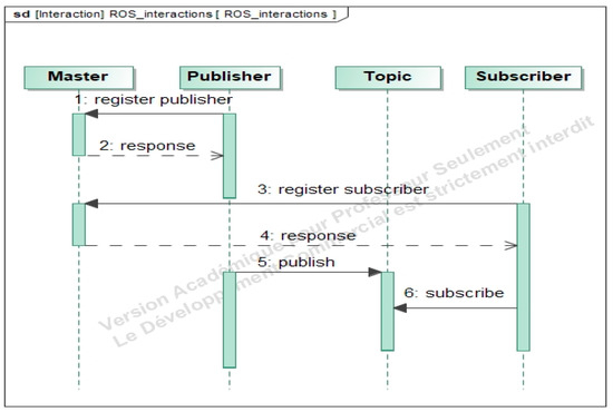
Figure 1.
Robot Operating System (ROS) system process.
Despite the IVV capabilities offered by ROS, the greatest challenge is balancing the needs and diverse priorities of stakeholders involved in the development of a robotic system. ROS enables code reuse from seasoned hobbyists, students, researchers, entrepreneurs, and developers, who write code for cars, boats, airplanes, humanoids, and toys, among a myriad of other applications. But there is a need to constantly work to balance and prioritize the use cases that developers want to implement. On the other hand, the absence of a development methodology makes the integration task complex, which often means that a lot of time is spent adapting the different codes developed elsewhere.
To overcome the challenges described above, we propose in this paper a new approach based on swarm robotics combing SysML and ROS possibilities. SysML will be used to specify system requirements, identify the collective AGV system behaviors required, describe the different AGV use-cases, and model the AGV architecture according to different viewpoints (behavioral, functional, and structural). ROS, on the other hand, will be used to adapt existing baseline robots with the SysML information model to implement the robot components and validate the design with simulation in the ROS environment. In the next section, we detail how the schematic information captured in SysML is converted into a format that can be used to produce or integrate software code that can then be simulated in ROS to ensure compliance with system requirements.
3. Integrated Methodology for Designing AGVs
AGVs can be considered modern mechatronic systems providing an increasing number of functionalities [35]. Our objective is to develop a design method allowing specialists from different engineering fields to combine their expertise to ensure functional, physical, and software integration using SysML and ROS. Indeed, today’s need for AGVs development is a closer integration which encompasses various factors related to design practices and tools, design methods, and design team members and their interactions.
The AGV design approach proposed in this article is based on swarm robotic concepts and it consists of two phases: a top-down phase from the requirements specification to functional and structural modeling using SysML; with a bottom-up phase for the integration of models and their implementation in ROS. The swarm designer begins by specifying the design requirements using SysML diagrams to describe the various swarm system needs. From these requirements, the designer identifies the different functions that build the collective swarm behaviors. SysML state-machine diagrams and activity diagrams are therefore used to model swarm behaviors. To ensure high-level traceability between requirements, behaviors, and functions, the designer uses the allocation matrices (Requirement-Behavior, Behavior-Function). These matrices trace the specified requirements with the functions that the AGV system must perform while respecting swarm behavior. Once the collective behaviors are modeled, the designer is interested in structural modeling. Using the SysML block definition diagram (BDD) and internal block diagram (IBD), the designer details the AGV structure by specifying the components that are able to ensure the previously modeled functions that the AGV must perform [36].
To ensure code integration, the designer follows a bottom-up approach guided by the SysML model developed in the previous steps to implement the swarm behavior with ROS. At this level of design, the structure of the AGV system is modeled with a Unified Robot Description Format (URDF) file based on BDD and IBD SysML diagrams. In addition, the system environment is described in ROS by creating a world file based on a context BDD-SysML diagram. The final simulation of the swarm behavior of AGVs is performed with ROS/Gazebo to meet the requirements described with SysML requirement diagrams. Figure 2 represents the steps of the proposed integrated design methodology. These steps are detailed in the following sections.
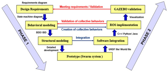
Figure 2.
Integrated methodology for designing a swarm system.
3.1. PHASE 1: SysML Modeling
3.1.1. Design Requirements
The design requirements are the needs, necessities, and expectations that the developed swarm robotic system must meet, or the constraints that it must satisfy [37]. The requirements diagram that is shown in Figure 3 models the general swarm robotic requirements to be verified. This model facilitates the designer to relate the solutions to be implemented with the needs defined in the specifications. Design requirements translate, through functionalities or constraints (performance, reliability, safety conditions, etc.), what must be satisfied by the system [36].
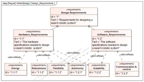
Figure 3.
Design requirements of a swarm robotic system in SysML.
These requirements are divided into main sub-requirements. To design a swarm robotic system, the designer must identify the necessary hardware and software specifications. To cite some examples of requirements, the robots need to be autonomous, located in their environment, can act to modify it, and can detect each other. Additionally, the detection and communication capacities of the robots must be local. These robots should also not have access to centralized control and/or global knowledge [38].
3.1.2. Behavioral Modeling
After specifying the hardware and software requirements, the designer is interested in the behavioral modeling of the swarm robotic system. Indeed, Brambilla et al. [38] have classified the behaviors of swarm robots into four classes: spatial organization behaviors, navigation behaviors, collective decision making, and other collective behaviors. In previous work, ALOUI et al. [36] proposed an approach for the modeling of the collective behaviors of swarm robots using SysML state machine diagrams.
The collective behavior of a swarm generally consists of a set of functions performed by each robot in the swarm. The interaction between the robots synthesizes the collective behavior of a swarm of robots. Figure 4 describes the behavior of each robot in the swarm. Therefore, the use of SysML state machine diagrams ensures the modeling continuity between the swarm behavior description, the robot behavior, and the functional behavior of a robot.
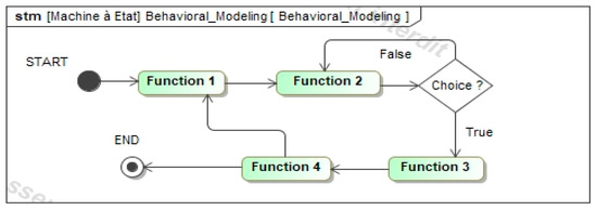
Figure 4.
Abstract model of collective behavior in SysML.
3.1.3. Structural Modeling
After identifying the set of functions that describe the collective swarm behaviors, the necessary components of the AGV system need to be defined. Figure 5 represents the general architecture of the swarm system represented with a SysML BDD.
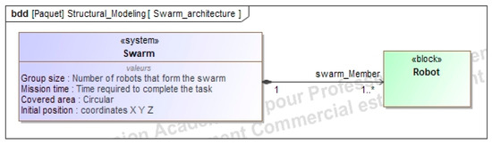
Figure 5.
General architecture of the swarm in SysML.
The next step consists of identifying the different alternative solutions that can meet the functional architecture of the AGV system. Then, the final structure of the AGV is broken down into subsystems and components. Figure 6 shows a general structure with the different elements of an AGV in a swarm.
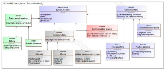
Figure 6.
The swarm member structure modeled with the SysML BDD diagram.
The structure of the swarm member depends on the functions required. Generally, robots consist of a motion system such as motors to operate and wheels to provide movement. In addition, the robots contain a power supply system consisting mainly of batteries to provide energy. Other components are specified according to the appropriate behavior such as position sensors to provide localization and infrared sensors to explore the environment.
To ensure the design continuity and consistency of the methodology, the designer creates an allocation matrix that links the hardware components of the swarm system with the individual functions provided by each swarm robot. Figure 7 represents a component-function allocation matrix.
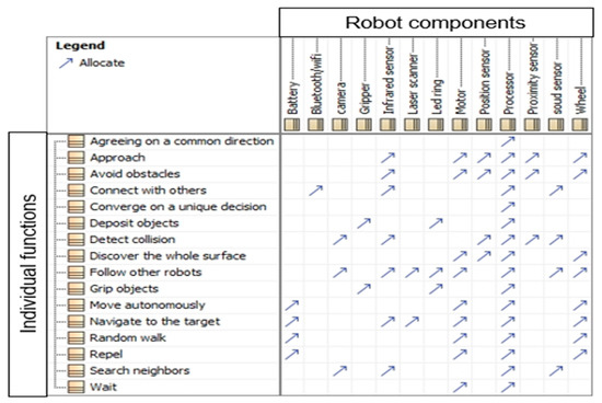
Figure 7.
Component-Function allocations.
3.2. PHASE 2: ROS Implementation
The Robotics Operating System (ROS) is the first large-scale robotics collaborative project that provides a time-saving computer toolset in the development of a robot, or robotic system [39]. The main idea for creating a swarm of robots on ROS is to create a decentralized communication system made up of a set of individual robots. These robots represent the nodes of the ROS system and a communication topic to subscribe and publish information between them. Figure 8 represents the interactions of swarm robots in the ROS environment.
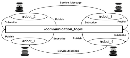
Figure 8.
Interactions of swarm robots in the ROS environment.
To implement the model developed on ROS, the swarm designer creates a workspace made up of different packages which describe the swarm structure and the functions provided by each robot. For the organization of ROS packages, it is a good practice to group them together for functional consistency [40]. It is possible to do this as a workspace. Figure 9 shows an architecture of a swarm robot package.
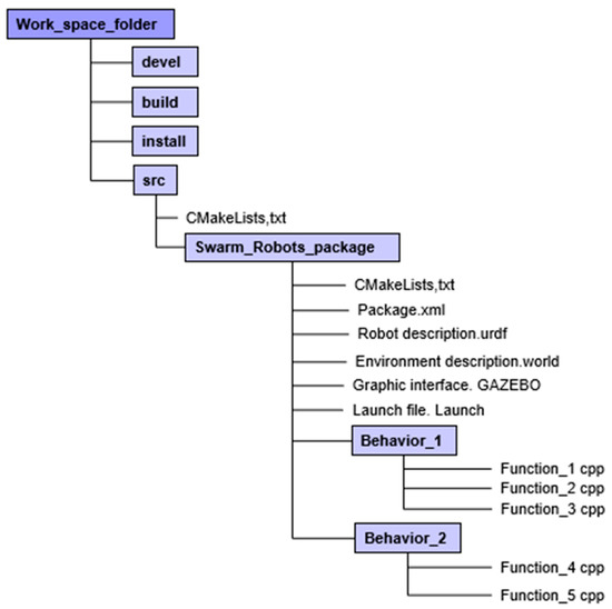
Figure 9.
Organization of the workspace of a swarm member in ROS.
In this workspace, a ‘src’ directory is created in which a package directory that contains the files of a package can be created [41]:
- -
- The build directory is used for building packages and as such contains all object files.
- -
- The devel directory contains the executables and the libraries resulting from the compilation of the packages and, therefore, specified as a target in the CMakeLists.txt file.
- -
- The install directory only contains files that are explicitly installed through the installation directives specified in the CMakeLists.txt file of the packages.
- -
- CMakeLists.txt: The file indicating how to compile and install the package
- -
- package.xml: The ROS file describing the identity of the package and its dependencies.
- -
- A robot description language: URDF for Universal Robot Description Format is an XML specification describing the kinematics of a robot, its dynamic characteristics, its geometry, and its sensors.
- -
- WORLD file: this file describes the work environment. It can correspond to the context diagram (BDD) which defines the SysML environment.
- -
- A node as an executable file in ROS package: ROS nodes use a client library to communicate with other nodes. Nodes can subscribe or publish to topics. Nodes can use or provide a service. The client libraries are rospy for python and roscpp for C++. These ROS nodes contain the algorithms that translate the individual functions of the robots.
- -
- Launch file: In this file, the developer must request the other files (urdf file, world file, cpp functions, etc.) and initialize the initial parameters of the system (swarm size, area, etc.) to describe the collective behaviors of swarm robots.
- -
- The graphical interface GAZEBO represents the final 3D view of the swarm system.
- -
- The last step of the proposed design approach is to validate the AGV design by checking all the design requirements. This step will be illustrated in the case study subject of the next section.
4. Case-Study: Application to the Design of AGVs
Automated guided vehicles (AGVs) are driverless mobile platforms used in the industry for the transportation of materials [42]. In this case study, we consider the design of a general-purpose AGV system that can be adapted to several working environments to transport material.
4.1. PHASE 1: SysML Modeling
4.1.1. Design Requirements
AGVs are deployed in many different application domains and vehicle types have increased to meet the customer’s needs. These types of vehicles are used in the manufacturing, automotive, warehousing, food, chemical, and healthcare industries [43,44]. This variety of applications specifies the general-purpose system requirements. The first SysML diagram to be addressed is the requirements diagram for the AGV model shown in Figure 10. As shown in this figure, a traceability relation “satisfy” is added to ensure traceability between the different design views. Indeed, when dealing with complex systems design, this traceability is essential because it helps in verifying that the requirements are met for each component of the system and for the system as a whole.
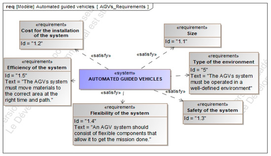
Figure 10.
Requirement diagram of automatically guided vehicles (AGV) in SysML.
The design of AGV systems is costly in terms of money and time because it should take into consideration the whole system life cycle, including the installation phase and logistics. Indeed, defining the AGV traffic rules and the path map is a time-consuming operation that could increase both installation and operation costs. In addition, one of the main requirements for the design of AGVs systems is efficiency. It is the main reason for adopting an AGV system for industrial logistics. In addition, the use of AGV introduces flexibility into the logistics system. Finally, AGVs need to be intrinsically safe, to never cause injuries to humans. Some major AGV design requirements have been listed above, but the list could be as large as this depending on specific needs. In addition, emerging design requirements may appear during the design cycle depending on the decisions made and the choices of solutions and technologies used. At this level, we limit ourselves to the major requirements which allow us to begin the study of the behavior of AGVs and, in particular, their behavior in swarms.
4.1.2. Behavioral Modeling
The automated guided vehicles (AGVs) are used for automated factory logistics, such as the transportation of raw materials or final products. They are used for the management of the flow of resources between the point of origin and the point of destination in order to meet certain stakeholders’ requirements, for example, companies or customers [6].
The analysis of the behavior of the AGVs begins with the description of the scenarios of use and the missions to be accomplished by the AGVs. In SysML language, the scenarios of use can be modeled using SysML use-case diagrams. The AGV mission can be modeled with a state-machine diagram as is detailed below.
AGV scenario: An AGV usually transfers a pallet of goods from an automated production line. The pallet must be brought to the shipping area. Sometimes pallets have to be stored in a warehouse that is composed of a set of racks and shelves or a set of block storage areas. Figure 11 represents this AGV scenario.
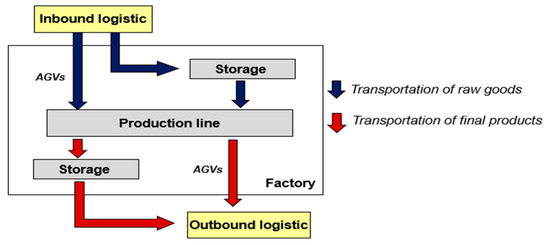
Figure 11.
AGV scenario.
AGV missions: A mission must be accomplished by an AGV. It is started with a task defined as a sequence of segments of the route map to be followed by AGVs. Thereafter, each trip is made by an AGV to move a pallet of goods from one place to another. Indeed, the loading and unloading operations are carried out at the beginning and the end of each journey. To apply the swarm aspect, each AGV performs the mission in parallel with the other AGVs (i.e., throughout the mission, each AGV performs a task of the mission). This mission can be defined using the state machine diagram shown in Figure 12.
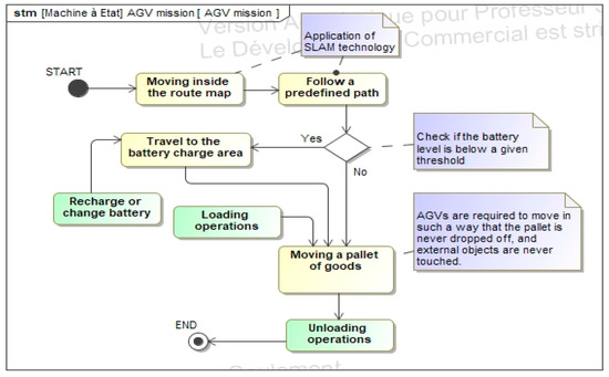
Figure 12.
AGV missions in SysML.
4.1.3. Structural Modeling
In this step, the general structure of the AGV system must be defined. For this, the AGV structure follows the description given in a block definition diagram as shown in Figure 5. The AGV swarm consists of a group of AGV individuals. The block definition diagram shown in Figure 13 represents the structure of the main sub-systems and components of one AGV. The motion sub-system of the AGV consists of four wheels and four motors. Each wheel is driven by one servo-motor with an assembled gearbox. The system should have four drivers that receive commands and send feedback to the 4-axis controller board. In addition, the power supply subsystem of each AGV consists of a self-contained battery. One stereo camera chosen to be Intel Real Sense D435i [45] is added to the front of the vehicle body to collect RGB images and depth information [46].
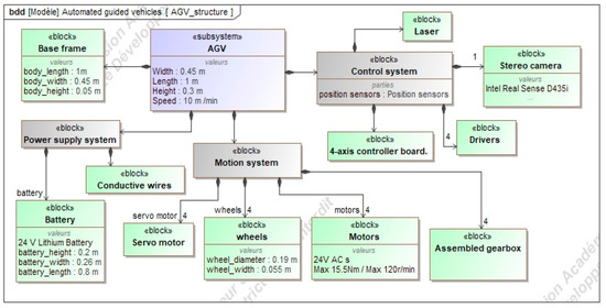
Figure 13.
Architecture of the AGV system in SysML.
To ensure the continuity and consistency of the design, another allocation matrix must be defined to relate the hardware components of the AGVs system to the individual functions provided by each AGV. Figure 14 shows this component-function allocation matrix.
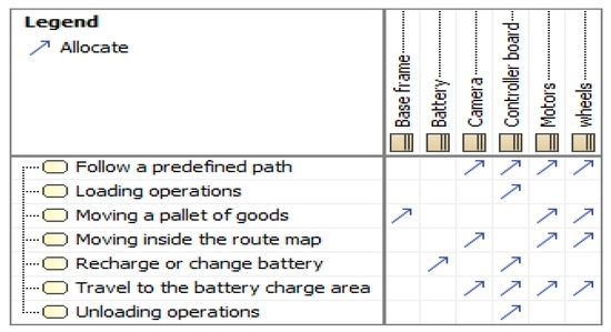
Figure 14.
Component-Function allocations.
4.2. PHASE 2: ROS Implementation
To verify the development performed in the previous phase, the developed models of the AGV system need to be implemented in the ROS environment. For this, the designer creates a workspace composed of a set of packages. To take into account the behavior of the swarm, the individual AGVs are associated with nodes in the ROS system, and a communication subject is created for subscribing and posting information exchanged between the individual AGVs. The ROS packages are implemented based on the different SysML diagrams developed in the first design phase. Indeed, the BDD block definition diagram and the IBD internal block diagrams are used to create the URDF file and the WORLD file in ROS. The URDF file describes the general structure of the AGV system and the WORLD file describes the working environment (factory). Then the state machine diagrams and the activity diagrams are used to develop the control algorithms of the AGV system in ROS. Figure 15 shows the ROS integration methodology.
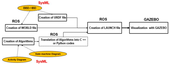
Figure 15.
ROS integration methodology.
One of the strong points of ROS is the reuse of codes developed by others that can be found and shared by ROS users (on GitHub site for example). Users can find versions written in Python and C++ which differ in their restrictions, performance, and the lighten code. AGV developers can download them and make them usable by compiling them (using catkin build processes), and new versions of these codes will be available as other ROS-based packages. Based on the SysML descriptions made in the first design step, AGV developers can integrate the most suitable codes that respect the AGV requirements, the functional architecture, and its physical architecture. The software architecture will therefore be more easily integrated based on the existing ROS packages. The developer’s task after that is to adapt the code and integrate it with the remaining ROS elements. In this study, we choose to adapt the “agvs” packages developed by the company Robotnik Automation [47] to our case study to validate our methodology. We followed a bottom-up approach guided by a SysML information model to select a baseline solution of an AGV in order to create a new AGV design that met the system requirements. This saved a lot of time in the AGV design process. In the next sections, we will detail how to implement one single AGV system in the ROS platform. Some remarks will therefore be given on the simulation of the swarm of AGVs.
4.2.1. Creation of URDF File
The first step is to create the URDF descriptive model of the AGV for the simulation purpose with the Gazebo tool (the 3D environment of ROS for simulation). The URDF file can be directly defined using Gazebo tools based on the SysML description of the AGV structure. However, for a complex 3D design of an AGV, it would be more practical to generate the URDF file from a 3D CAD tool. For this, some CAD tools, such as SolidWorks and FreeCad, have plugins allowing the automatic generation of the URDF file by specifying the robot joints and links. In such a case, the SysML description of the robot structure can be used by the CAD designer to define the 3D CAD model of the AGV. Figure 16 shows the procedure for making a multibody model for the Gazebo environment using the SolidWorks plugin (SW2URDF). For each AGV link (component), it is necessary to specify the name, the collision type, and the visual component. It is also possible to add cameras, sensors, or motors to the links. At this stage, the values of the physical properties can be defined for each component as specified in the SysML structure model of the AGV.
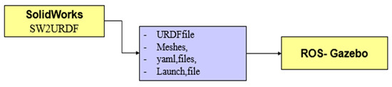
Figure 16.
Modeling of an AGV system from Solid Works to Gazebo.
Through CAD software, such as SolidWorks, the SysML BDD shown in Figure 13 helps the 3D CAD designer in modeling the AGV structure. This diagram defines the different components of the system with their physical properties. On the other hand, the Internal Block diagram (IBD) illustrated in Figure 17 explains the interactions between the components that help in defining the different links and joints between the AGV elements during the URDF file generation.
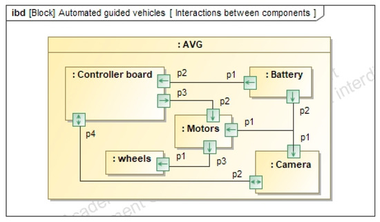
Figure 17.
Interaction between system components in SysML.
Figure 18 shows the 3D structure of the AGV according to the model developed with the IBD and BDD diagrams. The width and length are 0.45 m and 1 m respectively and the height is 0.3 m. This AGV structure is made of four wheels and four motors. Each wheel is driven by a servo-motor with an assembled gearbox and each AGV contains an autonomous battery.
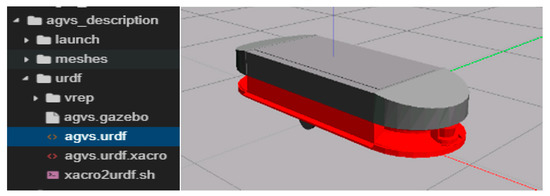
Figure 18.
3D model of an AGV in Gazebo.
4.2.2. Creation of World File
The second step is to create a World file that describes the working environment. ROS users can reuse and adapt existing World files, or develop them using Gazebo or 3D CAD Software. In our study, the AGV system environment is a factory that has been adopted from the ROS/Gazebo library of World files. The file “agvs_office.world” contains the various factory elements as shown in Figure 19.
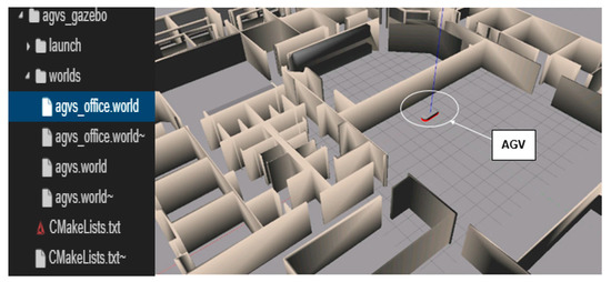
Figure 19.
3D model of a factory in Gazebo.
This factory is a flat surface made up of walls, racks, large pallets, empty pallets, and conveyor frames. All these components are available in the ROS library to build customizable working environments.
4.2.3. Creation of Algorithms
The third step is to create the algorithms that manage the operation of the AGV system in the factory. Our methodology simplifies the creation of these algorithms because the models developed with the state machine diagrams in SysML are used to develop these operating algorithms. Figure 20 shows the process of creating algorithms to run AGVs through SysML diagrams.
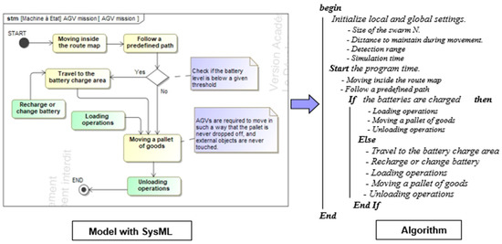
Figure 20.
Creation of AGVs operating algorithms using SysML diagram.
Converting these algorithms to usable software codes is the most difficult step that requires the ingenuity of IT developers. However, with the preliminary preparation work (state-machines to algorithms) the complexity of the task of the developers is considerably reduced, with a better level of conformity between the various pieces of code. Indeed, the IT developers translate the algorithms into C++ or Python codes to ROS nodes which will be called later by the run files. In most cases, IT developers can find some shared codes similar to the ones to be implemented in their application, thanks to code sharing by the ROS community. Their task is therefore to adapt the existing codes and add the missing ones while being guided by the SysML model.
As an example of code used in this case study, the simultaneous positioning and mapping (SLAM) code of the AGV system was implemented to draw a map by estimating its current location in an arbitrary space. SLAM is defined as the problem of building a map at the same time as locating the AGV in that plane. In fact, the AGV can rely on two sources of information: information specific to it and information collected in its environment. When it is in motion, the AGV can use dead reckoning and the information returned by its sensors (encoder wheels, the current consumption of motors, the position of a servomotor, etc.). However, this kind of information is not completely reliable (sliding, play, friction, etc.). The other source of information comes from sensors and systems dependent on the environment and external sources (camera and laser). Another ROS visualization environment (Rviz) can be used to see how the map is created when the robot is moving. After saving the map, it is possible to move the AGV on a chosen path. Figure 21 represents the Rviz visualization of an AGV moving on a path in the factory.
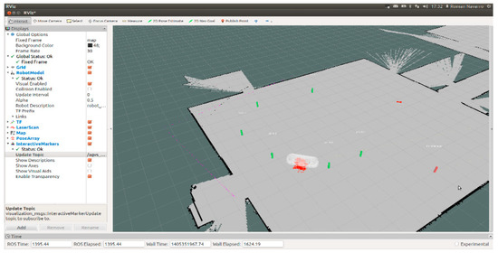
Figure 21.
Rviz visualization of an AGV moving on a path.
Finally, Gazebo allows visualizing the AGV system working in 3D. Figure 22 shows the moving of the AGV system in a 3D Gazebo environment. The goal of this simulation was to verify if the AGV is able to travel a memorized path and transport pallets of goods to the unloading area so that the main design requirement is verified with simulation.
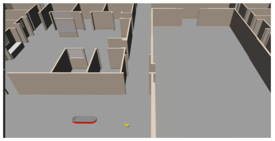
Figure 22.
Gazebo visualization of an AGV moving on a path.
The final step of the proposed design approach is the validation of the design requirements using ROS simulation based on the SysML description. Table 1 provides illustrative validation elements of three design requirements. The table shows the design, the requirements, the simulation actions performed in the ROS simulation environment, and the SysML information used for that purpose.

Table 1.
System satisfaction with initial requirements.
The simulation illustrated in Figure 22 shows only one AGV system. The simulation of the swarm of AGVs to test collision avoidance, coordination, and collaborative tasks is a work in progress that will be published in another article. Indeed, the simulation of a swarm of AGVs requires managing the number of AGVs in the ROS launch configuration file, but also a specific adaptation in the codes controlling each AGV.
5. Discussion
In the previous case study, we illustrated the top-down methodology based on SysML diagrams to model the AGV system. The modeling of the complex system is simplified because the method groups together the three views of the representations of the AGV (behavioral view, functional view, and structural view) within the same model. This type of modeling guarantees data consistency because the rules of SysML give each element of the model a unique definition, constructed by bringing together information from its different representations, and prevent them from contradicting each other. In addition, with the bottom-up methodology based on the ROS environment, it was easy for us to integrate existing codes and simulation environments for the AGV system according to the specifications made in the SysML model to adapt them to the specific AGV design. Indeed, the information contained in the SysML model helps the designer implement the 3D simulation model in ROS, the simulation environment, the AGV attributes, and the codes that should respect the algorithms specified in SysML for the behavior description. For this, the information in the different SysML diagrams (BDD, IBD, state machines, etc.) is transformed to the ROS files (XML files, URDF files, codes, etc.). The validation of the AGV system design with simulation requires defining the simulation test-cases according to the SysML requirement diagram.
6. Conclusions and Future Work
In this article, we presented a new integrated methodology based on swarm robotics principles for the design of automated guided vehicles. This methodology is based on two phases: a top-down phase using the MBSE method with SysML language and a bottom-up phase using the ROS software platform. This proposed methodology facilitates the design of complex systems such as AGV systems because it guides the designer from the requirements specification phase to the implementation phase. The numerical continuity during the design process is guaranteed by using the information in the SysML model for the AGV implementation in the ROS platform. The traceability is guaranteed by using SysML allocation and traceability matrices. The validation of the AGV design can be guaranteed by executing the different simulation scenarios described in SysML according to the design requirements. Finally, we believe that the implementation of this methodology by AGV manufacturers will be highly beneficial, both in terms of product quality and in reducing development times and design costs.
As perspectives, we suggest automating the data transformation from the SysML model to the ROS environment, by automating, for example, the creation of the URDF file from the BDD SysML diagram. We suggest also automating the validation of the requirements by developing a plugin in the ROS environment allowing access to the SysML model.
Author Contributions
Conceptualization, K.A. and A.G.; methodology, K.A.; software, K.A.; validation, A.G. and M.H. (Moncef Hammadi); formal analysis, A.G. and M.H. (Moncef Hammadi); investigation, K.A.; resources, K.A.; data curation, K.A.; writing—original draft preparation, K.A. and A.G.; writing—review and editing, K.A., M.H. (Moncef Hammadi) and A.G.; supervision, T.S. and M.H. (Mohamed Haddar); project administration, M.H. (Mohamed Haddar); All authors have read and agreed to the published version of the manuscript.
Funding
This research received no external funding.
Institutional Review Board Statement
Not applicable.
Informed Consent Statement
Not applicable.
Data Availability Statement
Not applicable.
Acknowledgments
The authors would like to thank the research department of ISAE-Supméca for covering the publication costs of this article.
Conflicts of Interest
The authors declare no conflict of interest.
References
- Vaidya, S.; Ambad, P.; et Bhosle, S. Industry 4.0—A glimpse. Procedia Manuf. 2018, 20, 233–238. [Google Scholar] [CrossRef]
- Lasi, H.; Fettke, P.; Kemper, H.-G.; Feld, T.; Hoffmann, M. Industry 4. Bus. Inf. Syst. Eng. 2014, 6, 239–242. [Google Scholar] [CrossRef]
- Ilanković, N.; Zelić, A.; Gubán, M.; Szabó, L. Smart factories–the product of Indrusty 4. Prosperitas 2020, 7, 19–30. [Google Scholar] [CrossRef]
- Benotsmane, R.; Dudás, L.; et Kovács, G. Collaborating robots in Industry 4.0 conception. In IOP Conference Series: Materials Science and Engineering; IOP Publishing: Bristol, UK, 2018; p. 012023. [Google Scholar]
- Ferraguti, F.; Pertosa, A.; Secchi, C.; Fantuzzi, C.; Bonfe, M. A Methodology for Comparative Analysis of Collaborative Robots for Industry 4. In Proceedings of the 2019 Design, Automation & Test in Europe Conference & Exhibition (DATE), Florence, Italy, 25–29 March 2019; pp. 1070–1075. [Google Scholar]
- Sabattini, L.; Digani, V.; Secchi, C.; Cotena, G.; Ronzoni, D.; Foppoli, M.; Oleari, F. Technological roadmap to boost the introduction of AGVs in industrial applications. In Proceedings of the 2013 IEEE 9th International Conference on Intelligent Computer Communication and Processing (ICCP), Cluj-Napoca, Romania, 5–7 September 2013; pp. 203–208. [Google Scholar]
- Saputra, R.P.; Rijanto, E. Automatic Guided Vehicles System and Its Coordination Control for Containers Terminal Logistics Application. arXiv 2021, arXiv:2104.08331. [Google Scholar]
- Stouten, B.; de Graaf, A.J. Cooperative transportation of a large object-development of an industrial application. In Proceedings of the IEEE International Conference on Robotics and Automation—ICRA’IEEE, New Orleans, LA, USA, 26 April–1 May 2004; pp. 2450–2455. [Google Scholar]
- Mahadevan, B.; Narendran, T.T. Design of an automated guided vehicle-based material handling system for a flexible manufacturing system. Int. J. Prod. Res. 1990, 28, 1611–1622. [Google Scholar] [CrossRef]
- Ronzoni, D.; Olmi, R.; Secchi, C.; Fantuzzi, C. AGV global localization using indistinguishable artificial land-marks. In Proceedings of the 2011 IEEE International Conference on Robotics and Automation, Shanghai, China, 9–13 May 2011; pp. 287–292. [Google Scholar]
- Luna, R.; Bekris, K.E. Network-guided multi-robot path planning in discrete representations. In Proceedings of the 2010 IEEE/RSJ International Conference on Intelligent Robots and Systems, Taipei, Taiwan, 18–22 October 2010; pp. 4596–4602. [Google Scholar]
- Rodríguez-Seda, E.J.; Stipanović, D.M.; Spong, M.W. Collision avoidance control with sensing uncertainties. In Proceedings of the 2011 American Control Conference, San Francisco, CA, USA, 29 June–1 July 2011; pp. 3363–3368. [Google Scholar]
- Sharma, B.; Vanualailai, J.; Prasad, A. A-Strategy: Facilitating Dual-Formation Control of a Virtually Connected Team. J. Adv. Transp. 2017, 2017, 9213805. [Google Scholar] [CrossRef]
- Rajamani, R. Vehicle Dynamics and Control; Springer: New York, NY, USA, 2012. [Google Scholar]
- Caruntu, C.F.; Ferariu, L.; Pascal, C.; Cleju, N.; Comsa, C.R. Connected cooperative control for multiple-lane automated vehicle flocking on highway scenarios. In Proceedings of the 2019 23rd International Conference on System Theory, Control and Computing (ICSTCC), Sinaia, Romania, 9–11 October 2019; pp. 791–796. [Google Scholar]
- Oyelere, S.S. The Application of Model Predictive Control (MPC) to Fast Systems such as Autonomous Ground Vehicles (AGV). IOSR J. Comput. Eng. 2014, 16, 27–37. [Google Scholar] [CrossRef]
- Caruntu, C.F.; Pascal, C.M.; Maxim, A.; Pauca, O. Bio-inspired Coordination and Control of Autonomous Vehicles in Future Manufacturing and Goods Transportation. IFAC-PapersOnLine 2020, 53, 10861–10866. [Google Scholar] [CrossRef]
- Mousavi, M.; Yap, H.J.; Musa, S.N.; Tahriri, F.; Dawal, S.Z.M. Multi-objective AGV scheduling in an FMS using a hybrid of genetic algorithm and particle swarm optimization. PLoS ONE 2017, 12, e0169817. [Google Scholar] [CrossRef] [PubMed]
- Jerald, J.; Asokan, P.; Prabaharan, G.; Saravanan, R. Scheduling optimisation of flexible manufacturing systems using particle swarm optimisation algorithm. Int. J. Adv. Manuf. Technol. 2004, 25, 964–971. [Google Scholar] [CrossRef]
- Ramos, A.L.; Ferreira, J.A.V.; Barcelo, J. Model-Based Systems Engineering: An Emerging Approach for Modern Systems. IEEE Trans. Syst. Man, Cybern. Part C Appl. Rev. 2011, 42, 101–111. [Google Scholar] [CrossRef]
- Barca, J.C.; Sekercioglu, Y.A. Swarm robotics reviewed. Robotica 2013, 31, 345–359. [Google Scholar] [CrossRef]
- Hamann, H.; Wörn, H. A framework of space–time continuous models for algorithm design in swarm robotics. Swarm Intell. 2008, 2, 209–239. [Google Scholar] [CrossRef]
- Lategahn, J.; Muller, M.; Rohrig, C. Global localization of automated guided vehicles in wireless networks. In Proceedings of the 2012 IEEE 1st International Symposium on Wireless Systems (IDAACS-SWS), Offenburg, Germany, 20–21 September 2012; pp. 7–12. [Google Scholar]
- Aloui, K.; Guizani, A.; Hammadi, M.; Soriano, T.; Haddar, M. System level specification and multi-agent simulation of manufacturing systems. In Proceedings of the Third Edition of the International Conference on Advanced Materials, Mechanics and Manufacturing, Beijing, China, 24–26 September 2021. [Google Scholar]
- Aloui, K.; Hammadi, M.; Soriano, T.; Guizani, A.; Haddar, M. On the continuity of the swarm robot design using MBSE method and simulation. In Proceedings of the 13th International Conference on Modelling, Optimization and Simulation (MOSIM’20), Agadir, Morocco, 12–14 November 2020. [Google Scholar]
- Ferreira, T.; Gorlach, I.A. Development of an automated guided vehicle controller using a model-based systems engineering approach. S. Afr. J. Ind. Eng. 2016, 27, 206–217. [Google Scholar]
- Barth, D.; Gorlach, I.A.; Gruhler, G. Development of a novel controller for a HVAF thermal spray process. In Proceedings of the International Conference on Competitive Manufacturing (Coma’10), Stellenbosch, South Africa, 3–5 February 2010. [Google Scholar]
- Brecher, C.; Nittinger, J.A.; Karlberger, A. Model-based Control of a Handling System with SysML. Procedia Comput. Sci. 2013, 16, 197–205. [Google Scholar] [CrossRef]
- Huang, E.; Ramamurthy, R.; McGinnis, L.F. System and simulation modeling using SYSML. In Proceedings of the 2007 Winter Simulation Conference, Washington, DC, USA, 9–12 December 2007; pp. 796–803. [Google Scholar]
- Mhenni, F.; Choley, J.Y.; Penas, O.; Plateaux, R.; Hammadi, M. A SysML-based methodology for mechatronic systems archi-tectural design. Adv. Eng. Inform. 2014, 28, 218–231. [Google Scholar] [CrossRef]
- Guizani, A.; Hammadi, M.; Choley, J.-Y.; Soriano, T.; Abbes, M.S.; Haddar, M. Multi-agent approach based on a design process for the optimization of mechatronic systems. Mech. Ind. 2017, 18, 507. [Google Scholar] [CrossRef][Green Version]
- ROS: The Agvs Package. 2015. Available online: http://wiki.ros.org/agvs (accessed on 4 April 2015).
- Martinez, A.; Fernández, E. Learning ROS for Robotics Programming; Packt Publishing Ltd.: Birmingham, UK, 2013. [Google Scholar]
- Quigley, M.; Gerkey, B.; Smart, W.D. Programming Robots with ROS: A Practical Introduction to the Robot Operating System; O’Reilly Media, Inc.: Newton, MA, USA, 2015. [Google Scholar]
- Boucher, M.; Houlihan, D. System Design: New Product Development for Mechatronics; Aberdeen Group: Boston, MA, USA, 2008. [Google Scholar]
- Aloui, K.; Guizani, A.; Hammadi, M.; Haddar, M.; Soriano, T. A Top down Approach to Ensure the Continuity of the Different Design Levels of Swarm Robots. In Proceedings of the 18th IEEE International Multi-Conference on Systems, Signals & Devices, Monastir, Tunisia, 22–25 March 2021. [Google Scholar]
- Schranz, M.; Bagnato, A.; Brosse, E.; Elmenreich, W. Modelling a CPS Swarm System: A Simple Case Study. In Proceedings of the 6th International Conference on Model-Driven Engineering and Software Development, Funchal, Portugal, 22–24 January 2018; pp. 615–624. [Google Scholar]
- Brambilla, M.; Ferrante, E.; Birattari, M.; Dorigo, M. Swarm robotics: A review from the swarm engineering perspective. Swarm Intell. 2013, 7, 1–41. [Google Scholar] [CrossRef]
- Koubâa, A. (Ed.) Robot Operating System (ROS); Springer: Cham, Switzerland, 2017. [Google Scholar]
- Stasse, O. Program/Simulation Tools/ROS/Gazebo/OpenHRP. Ph.D. Thesis, GdR Robotique, Inria Sophia Antipolis, France, 2019. [Google Scholar]
- Tuerlinckx, T.; Fisette, P.; Docquier, N. Robotran Embarqué: Robot Operating System. Ecole Polytechnique de Louvain, Université Catholique de Louvain. 2020. Available online: https://dial.uclouvain.be/downloader/downloader.php?pid=thesis%3A25226&datastream=PDF_01&cover=cover-mem (accessed on 8 June 2021).
- Grabd View Research. 2016. Available online: http://www.grandviewresearch.com/industryanalysis/automated-guided-vehicle-agv-market (accessed on 11 April 2017).
- Guizani, A.; Hammadi, M.; Choley, J.-Y.; Soriano, T.; Abbes, M.S.; Haddar, M. Multidisciplinary Optimization of Mechatronic Systems: Application to an Electric Vehicle. In Proceedings of the 2nd Annual International Conference on Material, Machines and Methods for Sustainable Development (MMMS2020); Springer: Cham, Switzerland, 2014; pp. 1–14. [Google Scholar]
- Walenta, R.; Schellekens, T.; Ferrein, A.; Schiffer, S. A decentralised system approach for controlling AGVs with ROS. In Proceedings of the 2017 IEEE AFRICON, Cape Town, South Africa, 18–20 September 2017; pp. 1436–1441. [Google Scholar] [CrossRef]
- Depth Camera D435i—Intel® RealSense™ Depth and Tracking Cameras. Available online: https://www.intelrealsense.com/depth-camera-d435i/ (accessed on 8 June 2021).
- Zhang, H.; Watanabe, K.; Motegi, K.; Shiraishi, Y. ROS Based Framework for Autonomous Driving of AGVs. In Proceedings of the IPS6-04, ICMEMIS, Kiryu, Japan, 4–6 December 2019. [Google Scholar]
- Available online: https://github.com/RobotnikAutomation/agvs (accessed on 8 June 2021).
Publisher’s Note: MDPI stays neutral with regard to jurisdictional claims in published maps and institutional affiliations. |
© 2021 by the authors. Licensee MDPI, Basel, Switzerland. This article is an open access article distributed under the terms and conditions of the Creative Commons Attribution (CC BY) license (https://creativecommons.org/licenses/by/4.0/).