Article

Design and Implementation of an Autonomous Charging Station for Agricultural Electrical Vehicles

by
El Houssein Chouaib Harik
Center for Precision Agriculture, The Norwegian Institute of Bioeconomy Research (NIBIO), Nylinna 226, 2849 Kapp, Norway
Appl. Sci. 2021, 11(13), 6168; https://doi.org/10.3390/app11136168
Submission received: 28 May 2021 / Revised: 19 June 2021 / Accepted: 29 June 2021 / Published: 2 July 2021
(This article belongs to the Collection Advances in Automation and Robotics)

Abstract

:
One of the goals in adopting more sustainable agricultural practices is to reduce green-house-gas emissions from current practices by replacing fossil-fuel-based heavy machinery with lighter, electrical ones. In a not-so-distant scenario where a single farmer owns a fleet of small electrical tractors/robots that can operate in an autonomous/semi-autonomous manner, this will bring along some logistic challenges. It will be highly impractical that the farmer follows each time a given vehicle moves to the charging point to manually charge it. We present in this paper the design and implementation of an autonomous charging station to be used for that purpose. The charging station is a combination of a holonomic mobile platform and a collaborative robotic arm. Vision-based navigation and detection are used in order to plug the power cable from the wall-plug to the vehicle and back to the wall-plug again when the vehicle has recharged its batteries or reached the required level to pursue its tasks in the field. A decision-tree-based scheme is used in order to define the necessary pick, navigate, and plug sequences to fulfill the charging task. Communication between the autonomous charging station and the vehicle is established in order to make the whole process completely autonomous without any manual intervention. We present in this paper the charging station, the docking mechanism, communication scheme, and the deployed algorithms to achieve the autonomous charging process for agricultural electrical vehicles. We also present real experiments performed using the developed platform on an electrical robot-tractor.

1. Introduction

Energy industries, manufacturing industries, traffic and the transport sector contribute significantly to greenhouse gas (GHG) emissions, and so does agriculture. Nevertheless, there is a major area that may be considered as “low-hanging fruit” in terms of GHG mitigation, which is the reduction of the emissions from agriculture, mainly tractor-related activities on the farm. To this end, several efforts are conducted from large tractor manufacturers [1,2] to provide an electrical alternative to the conventional fossil-based tractors. However, we believe that the main reason for the lack of commercially available electrical tractors, especially when compared to the growing success of electrical vehicles (EVs), is related to the strategy that these tractor manufacturers are following, namely when trying to provide the electrical alternatives with the same characteristics as the fossil-based ones. Because batteries have poorer mass energy density than fossil fuels, an electric tractor must be significantly heavier than a similarly powered diesel tractor in order to achieve a similar run-time. This will thus increase problems related to soil compaction, and raise concerns about the balance between charging versus working time [3].
Nevertheless, an alternative option is to replace heavy fossil-based tractors with a fleet of smaller, lighter tractors [4], or more recently a fleet of robots [5] that can work in a cooperative manner. The focus on greener alternatives of fossil-based machinery is on the rise [6], as the need for more sustainable practices to reduce the GHG emissions from the agricultural sector is considered in many countries as priority. In addition to that, the advantages of shifting to electrical alternatives of conventional agricultural machinery are numerous, as the electrical equivalent requires less maintenance [3], while there is a huge potential in producing the energy required directly on the farm [7]. In contrast, some challenges are to be solved before making this green shift a viable solution to the farmers, especially on the logistics side, as a fleet of small electrical tractors/robots will need to recharge their batteries more often as the battery packs size on these vehicles are small, and the current battery technology allows at best around 5 h of continuous labor for a 30 kW (40 horse power HP diesel-equivalent) commercially available electrical tractor [8], or for up to ten hours for an electrical weeding robot [9]. This means that if in a scenario where a farmer is in possession of a fleet of small size agricultural electrical vehicles (AEVs) that operate autonomously around the clock in a cooperative manner [10], there will be a need to manage the recharging process of their batteries, without this becoming an additional burden, otherwise it leads to an increased demand for manpower, which is already problematic in the agricultural sector [11].
To solve this problem, one can think about a similar solution to home vacuum cleaning robots, or industrial mobile platforms, where the mobile platforms docks into a specially fitted docking mechanism to recharge the batteries. To reach this, usually vision [12] is used in order to define the placing of the docking station, as this is usually the easiest thanks to the large body of existing computer vision software and hardware. In addition to that, it is considered to be the most-used method to define the position of the docking area when taking a fixed landmark as a reference [13]. Other efforts to use different sensing methods to define the position of the docking station were carried out, such as infrared (IR) [14], laser-based techniques [15], or even radio frequency identifiers (RFID) [16]. Regardless of the sensing method used to identify the docking area, each proposed solution is a customized one, fitted to a dedicated platform. Thus when trying to adapt this to the agricultural context as previously stated, a major problem is that the fleet is not necessarily homogeneous, and it will be not feasible to have a dedicated docking area for each AEV coming from a different manufacturer. In contrast to this issue, the automotive industry or their partners focusing on electrical vehicles, and have begun to inspect the solutions that can be deployed in parking places belonging to airports, malls, or offices, where the drivers can be away from their EVs for relatively long periods of time, usually enough to top-up the batteries of the EVs. These companies [17,18,19] begun to investigate the possibility of having an autonomous charging station that does not require a dedicated docking area, and that instead navigates to where the EV is parked, and plug the charging cable autonomously into the vehicle.
Building upon this idea, we present in this paper an autonomous charging station (ACS) composed of a holonomic mobile platform and a collaborative robot arm. The ACS navigates freely inside the garage where the AEV are parked, and plugs the power cable into the vehicles when they send a recharging request to the ACS. Nevertheless, the main challenge that hinders the implementation of such an idea is that AEV producers lacks standardization when it comes to charging ports. To this end, we present in this paper a simple, but unique, idea that consists of bringing the wall outlet to the AEV, instead of using a different plug for each AEV. The idea behind this is that, no matter the manufacturer of the AEV, it always comes with a common wall adapter, which in the case of this study, is the standard European type F Schuko plug [20]. This means that there will be no need for any special customization of the AEV in order to be compatible with the charging station mechanism. To make the whole process possible, we implemented machine-to-machine (m2m), and machine-to-server (m2s) communication paradigm, which allows the ACS to communicate directly with the concerned AEV in order to perform the plugging sequences, while updating the status of the operation to a central server for human supervision, mainly for security concerns, as there is no need for any human intervention in the whole process. A machine-state-based paradigm is used in order to create the sequence of actions required to fulfill the task of recharging the batteries of the AEV. Vision is used to detect the wall outlet, AEV socket, and to align both the mobile platform whether to the wall or to the AEV, and to perform the plug and unplug processes of the robotic arm.
The novelty of the work presented in this paper is threefold:
  • Holistic charging mechanism that is independent of the manufacturer of the vehicles.
  • Decision-tree-based scheme for controlling a combination of a robotic arm and an omnidirectional mobile platform.
  • To the best knowledge of the author, this is the first proof-of-concept of a dedicated autonomous charging solution for agricultural electrical vehicles.
The remainder of the paper is organized as follows: we present in Section 2 the hardware configuration of the ACS, the used plugs, and the decision-tree-based scheme. We also present the different controllers for the collaborative robotic arm and the mobile platform. In Section 3, we present the experimental results of the proposed platform. We give details on the different plug/unplug sequences. Section 4 is dedicated to the conclusion of the work presented in this paper.

2. Materials and Methods

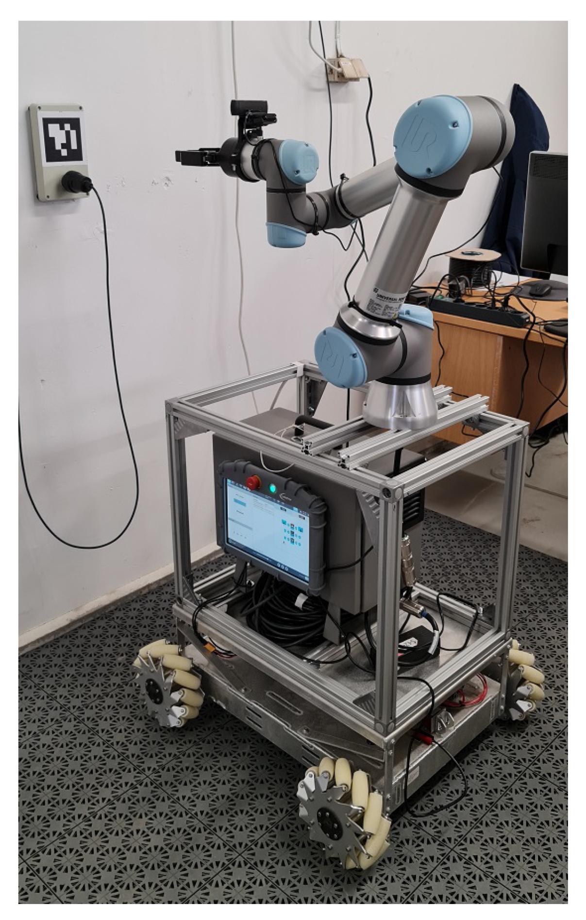
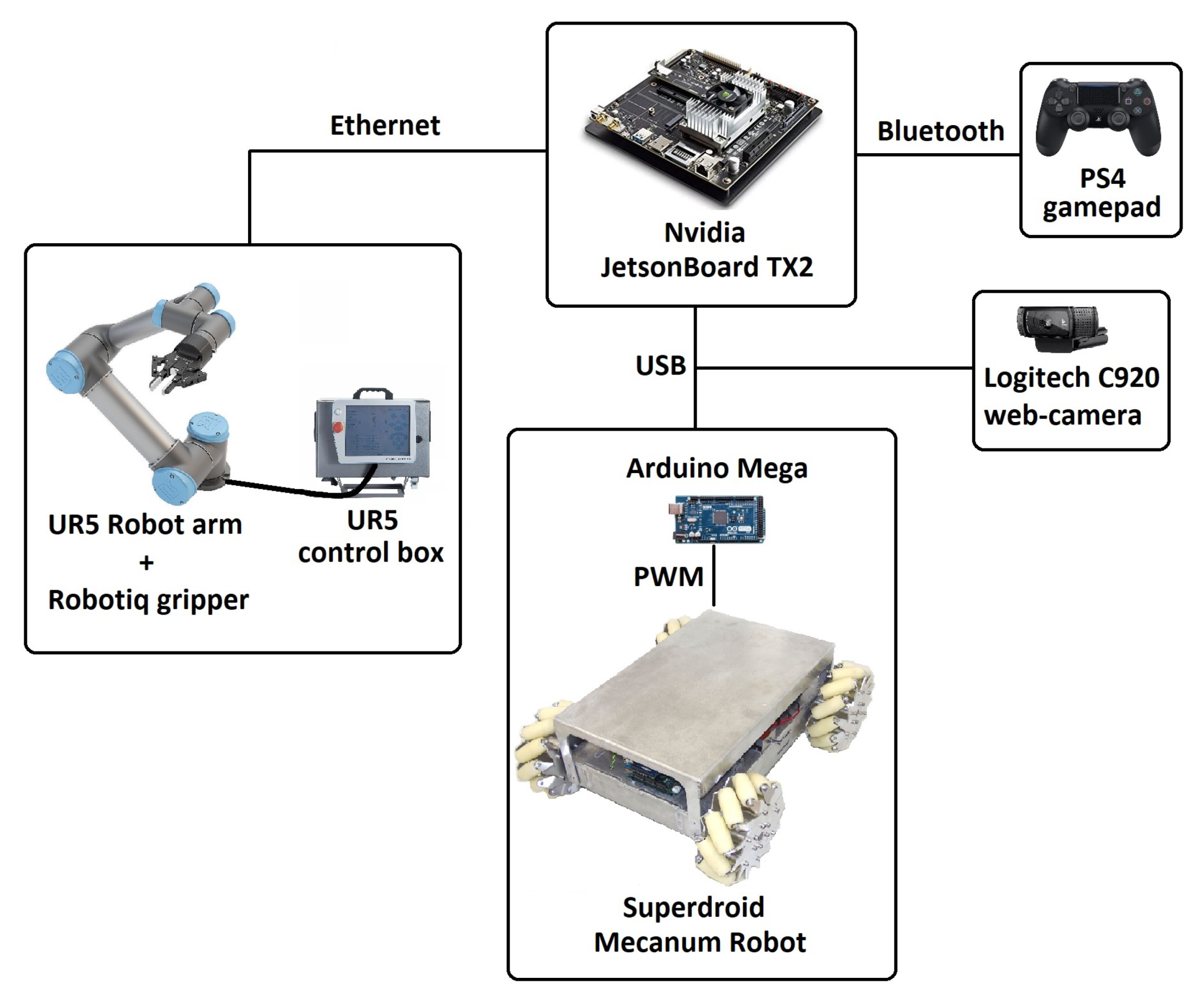
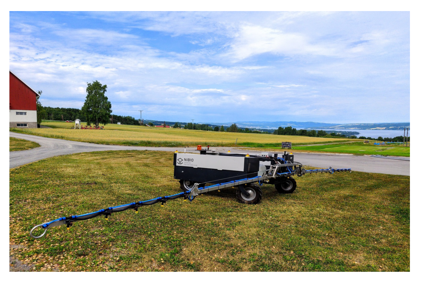
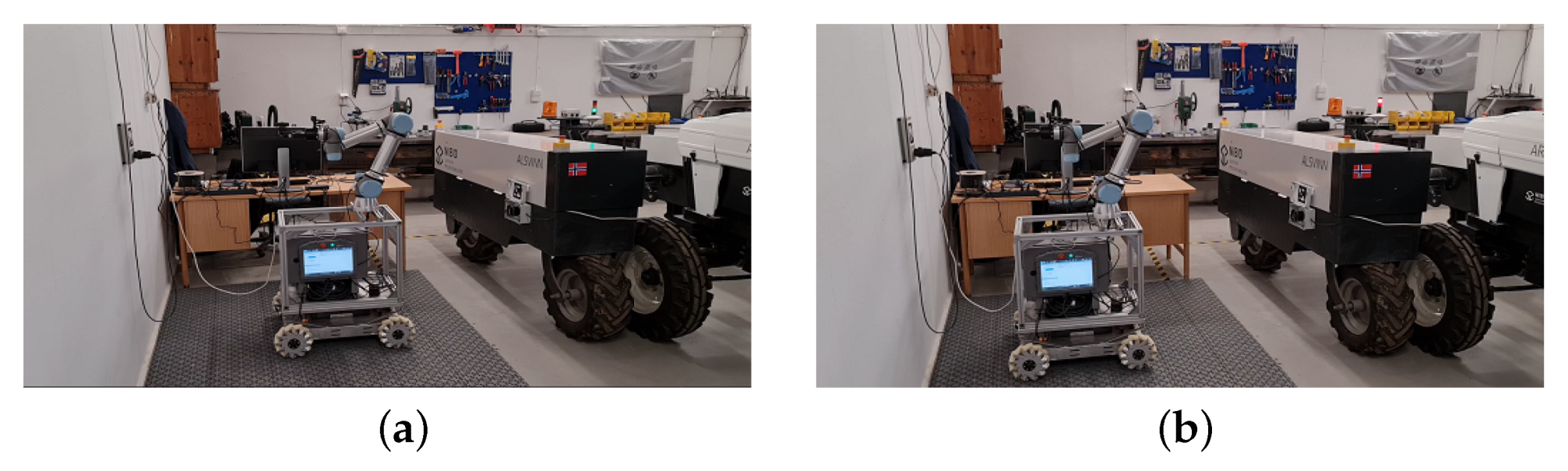
2.1. Hardware and Software Description
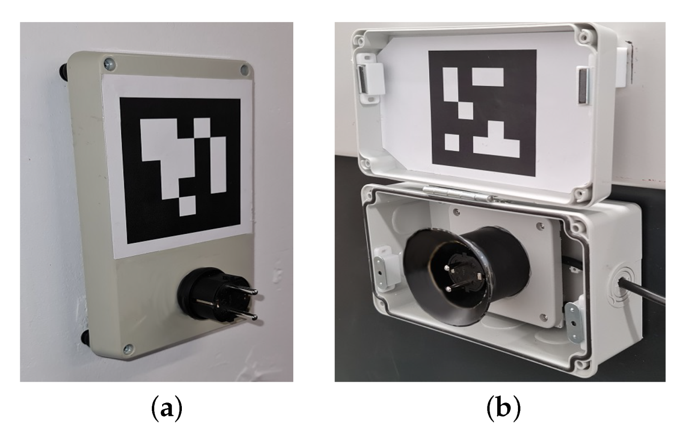
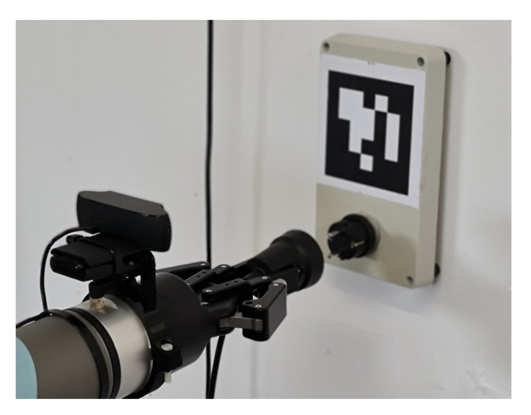
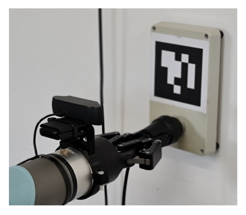
The ACS is a combination of a holonomic mobile platform carrying a collaborative robotic arm (Figure 1). The mobile platform (Programmable Mecanum Wheel Vectoring Robot-IG52 DB, Superdroid Robots, Fuquay-Varina, NC, USA) is a 4 mecanum wheel drive platform, which allows the platform to drive freely in X and Y 2D directions. The mobile platform Electronic Speed Controllers (ESCs) communicates with and Arduino mega board (Arduino Mega 2560, Arduino, Boston, MA, USA), which communicates through a serial connection with the main computer as we will see later.
A home-made frame was built in order to host the collaborative robotic arm. The frame is based on a Bosch Rexroth aluminum alloy strut, with a 30 × 30 mm profile. The different profiles of the frame have been connected using angle brackets, and fixing on the whole frame on the mobile platform was performed using a combination of T-slot nuts and profile screw connectors.
The arm is a UR5e (Universal Robot, Odense, Denmark), with a payload of 5 kg. Both the arm, its control box (which includes both the power supply, and the processing unit controlling the arm), and the teaching pendant are hosted on the mobile platform. The end-effector attached to the robotic arm is a two fingered 2F-85 gripper (Robotiq, QC, Canada), which has a stroke of 85 mm with a grip force up to 235 N, which is more than enough for our application. The Robotiq gripper is connected directly to the UR5e arm, and thus controlled via the embedded computer of the arm.
For the vision-based guidance of both the mobile platform and the robotic arm, we installed a simple RGB camera (C920, Logitech, Lausanne, Switzerland) on the end-effector.
The high level computer (HLC) consists of the NVIDIA Jetson TX2 Developer Kit (NVIDIA, Santa Clara, CA, USA). The board runs the Ubuntu 16.04 Linux distribution, and hosts the robot operating system [21]. ROS is the middleware that ensures the management of the different entities of the ACS. To control the collaborative robot arm, there were two options, whether to use Moveit [22], which is dedicated to calculate the inverse kinematics (translating a point into 3D coordinates to the joint angles of a robot arm) of the robot’s manipulators, and is integrated with ROS. The second option is to let the computer that came with the robot arm perform the job, by sending the desired commands via socket communication. We went for the second option as the Robotiq gripper is connected directly to the UR5e embedded computer, and as of the writing of this paper, there is no solution to control both the arm and the gripper via ROS as the gripper is connected to the embedded computer of the arm. A solution would be to detach the connection of the gripper from the arm, and make an external power and a USB serial connection to the Jetson board and connect it separately, a solution that is less ergonomic, which we wanted to avoid.
Finally, a PS4 (Playstation 4) gamepad is connected via Bluetooth to the Jetson board in order to ensure the ability of gaining manual control of the ACS at all times during the operations.
An overview of the global hardware composition of the different elements of the ACS as well as how the communication links each element to the central processing unit is illustrated in Figure 2.
When it comes to software architecture, the high-level computer is running Ubuntu 16.04, with the robot operating system (ROS) [21] as a middleware. Figure 3 illustrates the different ROS nodes running during the operation of the ACS. The main node plug_cycle is the manager of the inputs/outputs of the whole system; this node subscribes and publishes (obtain/send information from/to) to different topics that manages the corresponding hardware:
usb_cam: From the usb_cam ROS package [23]. This node publishes the RGB frames from the C920 RGB camera.
aruco_single. From the aruco_ros ROS package [24]. This node subscribes to the usb_cam node to obtain the rgb frames, and publishes the fiducial_transforms to the marker (if present in the images).
serial_node: From the rosserial_python ROS package [25]. The node ensures communication between the HLC and the mobile platform. The latter is controlled by an Arduino Mega board, which runs a node that subscribes to the velocity commands published by the plug_cycle node to control the transnational and rotational movements of the mobile platform.
joy_node: From the joy ROS package [26]. This node is responsible for establishing communication between the acs_main node and the PS4 gamepad. The gamepad is used to gain back manual control of the mobile platform at anytime by switching between the manual/auto mode by clicking on the corresponding button on the gamepad.
As for the robot arm, it has two operation modes: local and remote modes. The local mode allows the manual control or direct programming of the arm using the teaching pendant (the touchscreen that comes with the arm). When using the remote mode, the robot arm control box receives operation commands through network requests. To this end, the communication with the robot arm is ensured via the low-level networking interface (socket) [27]. More information about this mode of communication can be found in [28].
The communication between the ACS and the AEV is ensured via websockets. To this end, both roslibpy [29] and rosbridge_suite [30] to establish the communication, and allow inter-vehicle communication.
Figure 3 illustrates the global software architecture of the ACS.

2.2. The Plugs

The ACS has as a task to pick up the power-outlet from a wall-plug, plug it in the robot, unplug it again from the robot, and plug it again into the wall-plug. The idea as previously described consists in bringing the wall outlet to the robot. Initially the power-outlet is plugged into a dummy type F Schuko wall-plug, which serves only as a holding mechanism and is not powered (Figure 4a).
On the top of the wall-plug, we installed a squared fiducial marker [31] with a unique identifier. The marker serves as a reference to the ACS for the alignment and plug/unplug sequences as we will see in next section.
On the AEV side, we use the included AC–DC charging transformer that comes with the vehicle. The Schuko plug of the transformer is hosted in a box mounted on the vehicle. Similarly to the wall-plug, a fiducial marker with a different identifier is used as reference for the vision-based navigation and plug/unplug processes of the ACS. As the AEV is working in the fields, and to protect the marker from dust/mud, which make its detection not possible, we installed the marker on the inner-side of the box lid; this means that when the AEV is driving in the field, the box is closed, and thus the marker protected. When the AEV enters the garage, and requests to charge its batteries, the lid opens, and the marker becomes visible (Figure 4b). The idea is to install a servo-motor and fit it with the lid, but this is considered as a next step as the focus on this work is on the ACS and its core functionalities.
Please note that on the vehicle plug (Figure 4b) there exists a guiding socket (combination of a cylinder and half cone). This is indeed meant to be used for allowing a small amount of misalignment error during the plug-in process. The reason why it is on the vehicle plug and not on the wall-plug is purely mechanical. The wall-plug is fixed, with no moving parts, thus the marker will not change its position, meaning that there will be no errors when trying to estimate the position of the plug based on the marker. On the other hand, the lid is a moving part, this means that when it opens, there may be tiny misalignment, inducing errors in estimating the position of the vehicle plug, and that is why there is the guiding socket in the vehicle and not on the wall.

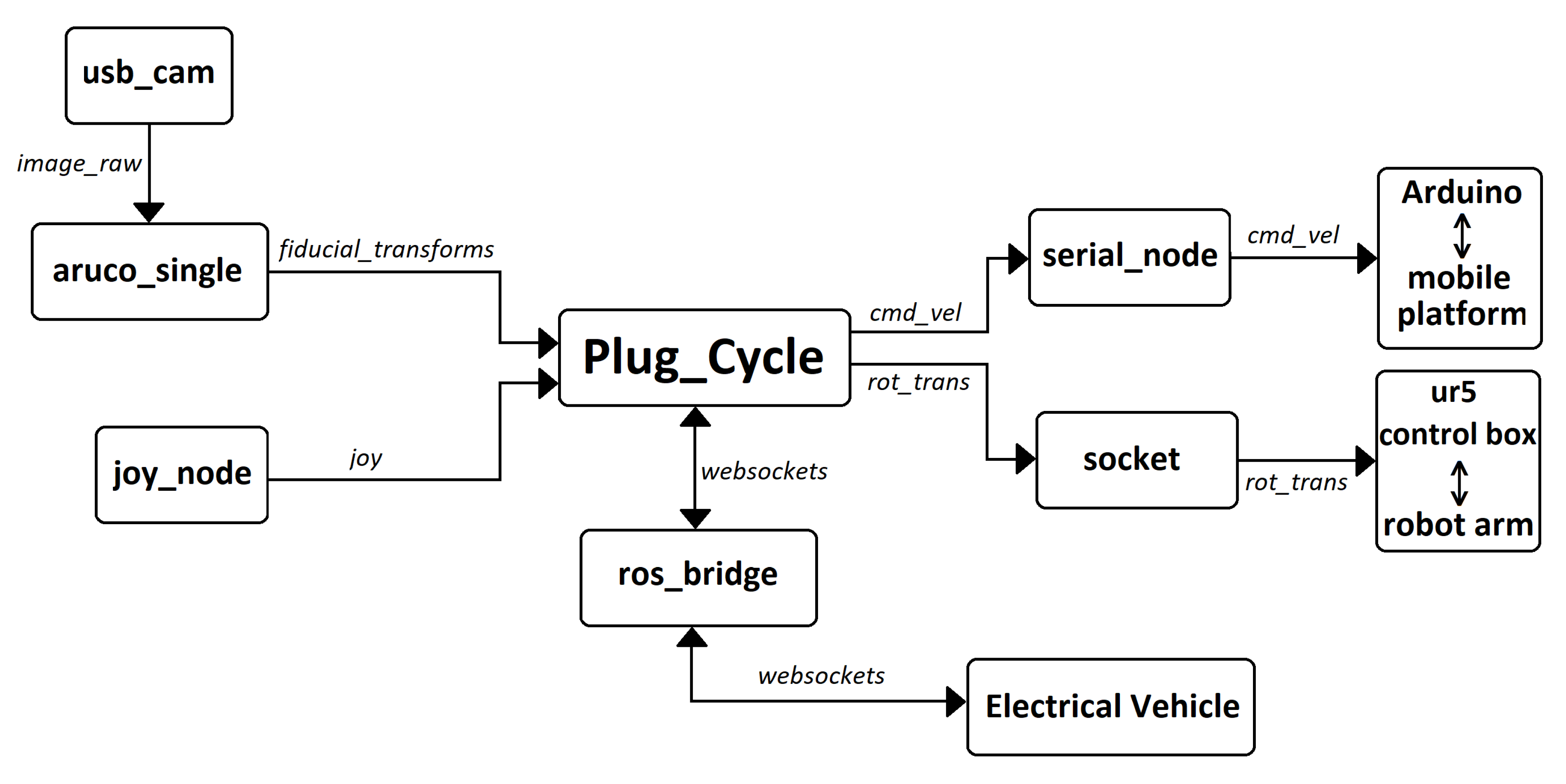
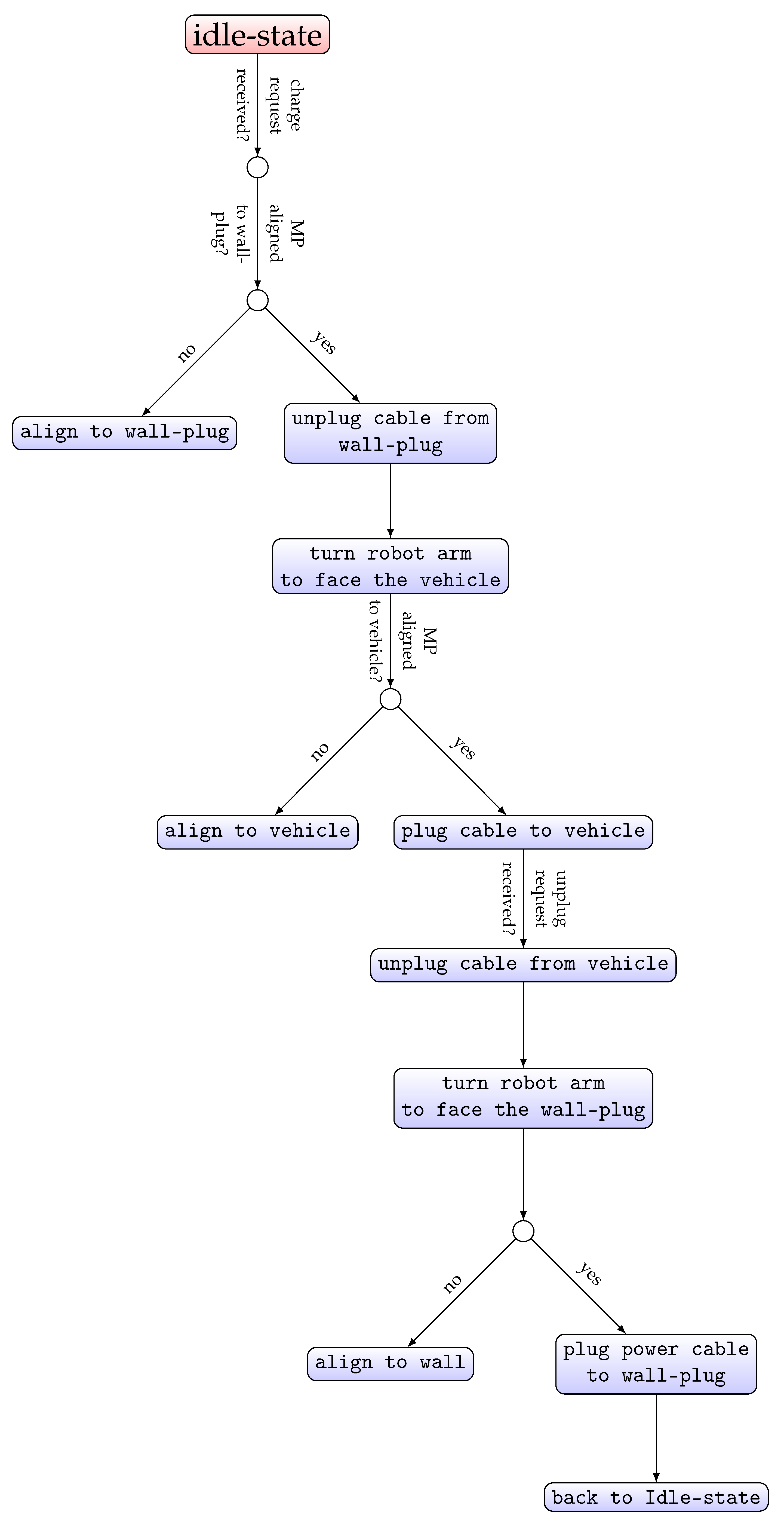
2.3. Decision-Tree Based Architecture

The software architecture is based on a decision-tree algorithm [32]. Each sequence is a set of conditions that need to be successfully fulfilled in order to move to the following sequence. The intuitive sequence of the commands that the ACS performs follows what a human would perform when performing the same task: going to where the charging cable sits, grab the cable, move towards the vehicle, and then plug the cable in. When the vehicle is finished charging, he/she would then unplug the cable, and sit it back in its original place for later use.
To automate the whole process using the ACS, we set two types of commands, those performed by the mobile platform (moving the whole ACS), and those performed by the robot arm (moving only the griper). When an AEV enters the garage, it sends a charge request to the ACS, which sits in an idle state. It is worth noting that the idle state of the ACS means that the gripper (and consequently the camera mounted on it), are facing the wall and that the wall-plug identifier is visible, as seen in Figure 1). When receiving the charge request, the ACS aligns itself to the wall-plug (only the mobile platform moving at this stage). Once the ACS is aligned to the wall-plug (at a predefined distance from the wall-plug), the unplug cable from wall-plug sequence begins, taking the wall-plug marker as a reference for the gripper to grasp the power-outlet. Once the power-outlet is unplugged from the wall-plug, the base of the robot arm turns 180 degrees to face the AEV. A new aligning sequence starts to align the ACS to the AEV. Once the ACS is at a predefined distance from the AEV, the plugging sequence begins. Once plugged in, the ACS informs the AEV that it successfully plugged the cable in, and the charging process begins. Once the AEV has recharged its batteries, or reached an acceptable level that allows it to continue its field tasks, it sends an unplug request to the ACS, the latter starts unplugging the power-outlet from the AEV. Once the power-outlet is unplugged from the AEV, the robot arm turns again 180 degrees to face the wall, and the ACS aligns itself to the wall-plug. When the ACS is aligned again to the wall-plug, the ACS plugs the power-outlet into the wall-plug, and returns to the idle state, waiting for new commands from other AEVs. The whole decision-tree is illustrated in Figure 5.

2.4. Controller’s Description

As previously stated, there are two types of commands for the ACS, one for the mobile platform to move in the planar surface of the garage, and the other one for the robot arm, to plug and unplug the power-outlet using the gripper. We provide in-depth detail in this section as to the definition of the sequences related to each of these two components of the ACS.

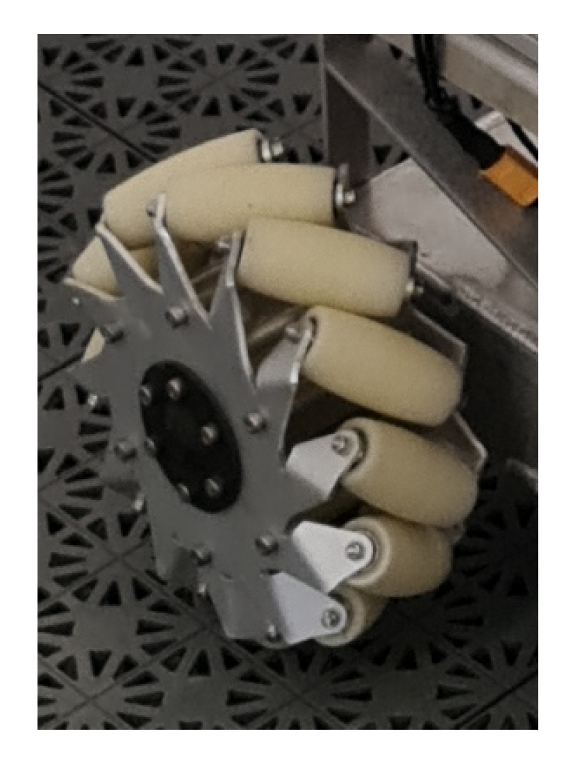
2.4.1. Mobile Platform Controller

The holonomic constraints of a mobile platform are directly related to the wheel constraints used on this platform, and more precisely the driving wheel constraints (a spherical wheel has no constraints, but yet it cannot be used as a driving wheel without additional mechanisms). To overcome the non-holonomic constraints, namely the lateral motion ones, the driving wheels to be used should be mecanum wheels. The particularity of these wheels is that they allow the vehicle to move freely in any direction in the planar surface, Figure 6 illustrates an example of a mecanum wheel as found on the ACS presented in this paper.
The mecanum wheel has rollers attached to the wheel perimeter with axes that are anti-parallel to the main axis of the fixed wheel component [33]. Combined with three similar actuated wheels, the mobile platform motion becomes omnidirectional. These kinds of platforms present an interesting kinematic property: there is no coupling between the x and y degrees of freedom of the mobile platform. In other words, this means that platform moves freely in any direction on the 2D plane.
The motion and the steering of an omnidirectional mobile platform is related to the speed and sense of rotation of its actuated wheels [34]. In a four wheel configuration, an example of a lateral motion in the direction of Y R axis can be obtained by rotating facing wheels in opposite directions, as shown in Figure 7.
As illustrated in Figure 5, there are two conditions (MP aligned to wall-plug, and MP aligned to vehicle), this means that the first step before starting the process of plugging/ unplugging the power cable is to have the whole ACS (namely the MP) aligned to the wall or the vehicle. To this end, the first control objective is to propose a kinematic controller that fulfills this condition.
In order to represent the wall, or the vehicle, we use fiducial markers [35] and the Aruco_detect package from UbiquityRobotics. The output topic of interest from the Aruco_detect package is the fiducial_transforms, which gives the relative pose of the marker to the camera. As the pose of the camera is initially known compared to the MP, we can use the information received from the Aruco_detect to align the MP to the wall (or the vehicle).
The control objective of the MP can be expressed as follows:
lim t X e ( t ) = d x lim t Y e ( t ) = 0 lim t α ( t ) = 0
where X e and Y e are the pose errors along ( X R , Y R ) axes. d x is the predefined distance that we want the MP to stop at before starting the plug/unplug process (where x can be A E V or w a l l p l u g ), and α is the angle between the MP the fiducial marker.
As the MP is omnidirectional, a simple proportional controller is sufficient to fulfill the control objective as expressed in (1).
V x = d 0 + ( k l * X e ) V y = k l * Y e V a = k a * α
where V x and V y are the linear velocities, and V a is the angular velocity of the MP; k l and k a are positive gains.
As this is a pure position controller, large X e and Y e errors means large V x , V y , and V a velocities. To keep the ACS from having brusque movements because of large errors on the V x and V y plane, saturation on the velocities has been added (3):
i f | V x / y / a | > V x / y / a m a x : V x / y / a = V x / y / a m a x i f   V x / y / a > 0 V x / y / a = V x / y / a m a x i f   V x / y / a < 0
The velocity commands are then sent through a serial communication to the low-level controller of the MP, which will then interpret the commands into pulse width modulation (PWM) signals to each of the four motors to control the rotation speed of the wheels.

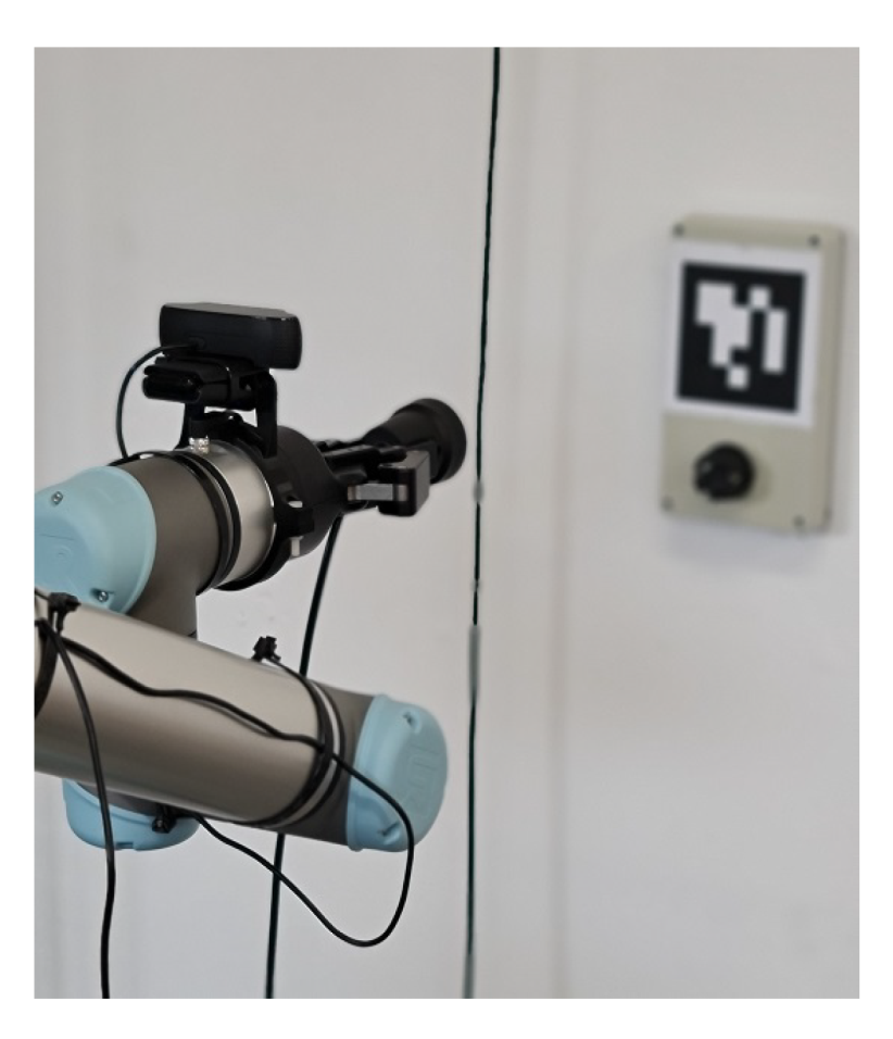
2.4.2. Robot Arm Controller

The control of the robot arm is relatively easier than the MP as all is needed is to send the point coordinates of where we want the gripper to be located at, and the processing unit controlling the arm does the inverse kinematics calculation (transforming a given 3D point into angles for the joints of the arm).
If we take the example of a plug sequence, initially, the coordinates of the fiducial marker (wall-plug or vehicle) are obtained. Then, a socket request to the computing unit of the arm is sent in order to obtain the gripper’s position in space. Having both the coordinates of the target and the gripper, the gripper’s position is adjusted so it is centered with the marker. The idea behind this is simply because there is no external information about the position of both the MP and the gripper in space, that is why there is a need for a first alignment with the fiducial marker; then, we proceed with the rest of the plug/unplug sequences.
Once the gripper is at a known location compared to the marker (Figure 8), and since we already know where the plug is located compared to the reference fiducial marker, we can now move to the second step.
Now that the gripper is at a known location, the second step consists of moving it to a predefined approach waypoint at the same speed as the previous centering step (Figure 9).
Each time we send a new waypoint to the robot arm, we wait for the feedback from the latter to signal that the arm has successfully reached that waypoint (if all the joints are at the angle obtained from the inverse kinematic calculation performed by the robot arm processing unit, we assume that the gripper has reach the desired waypoint), and there were no collisions while performing the trajectory calculated from the processing unit of the arm.
After that, the gripper is at the approach waypoint, for safety reasons (both the arm, the gripper, and the plug) we initiate the plug action (Figure 10) at a reduced speed. Algorithm 1 provides more details about the different steps needed in order to control the robot arm for plug sequence (the unplug sequence should follow similar steps, with the difference of closing and opening the gripper).
Algorithm 1: Plug control sequence.
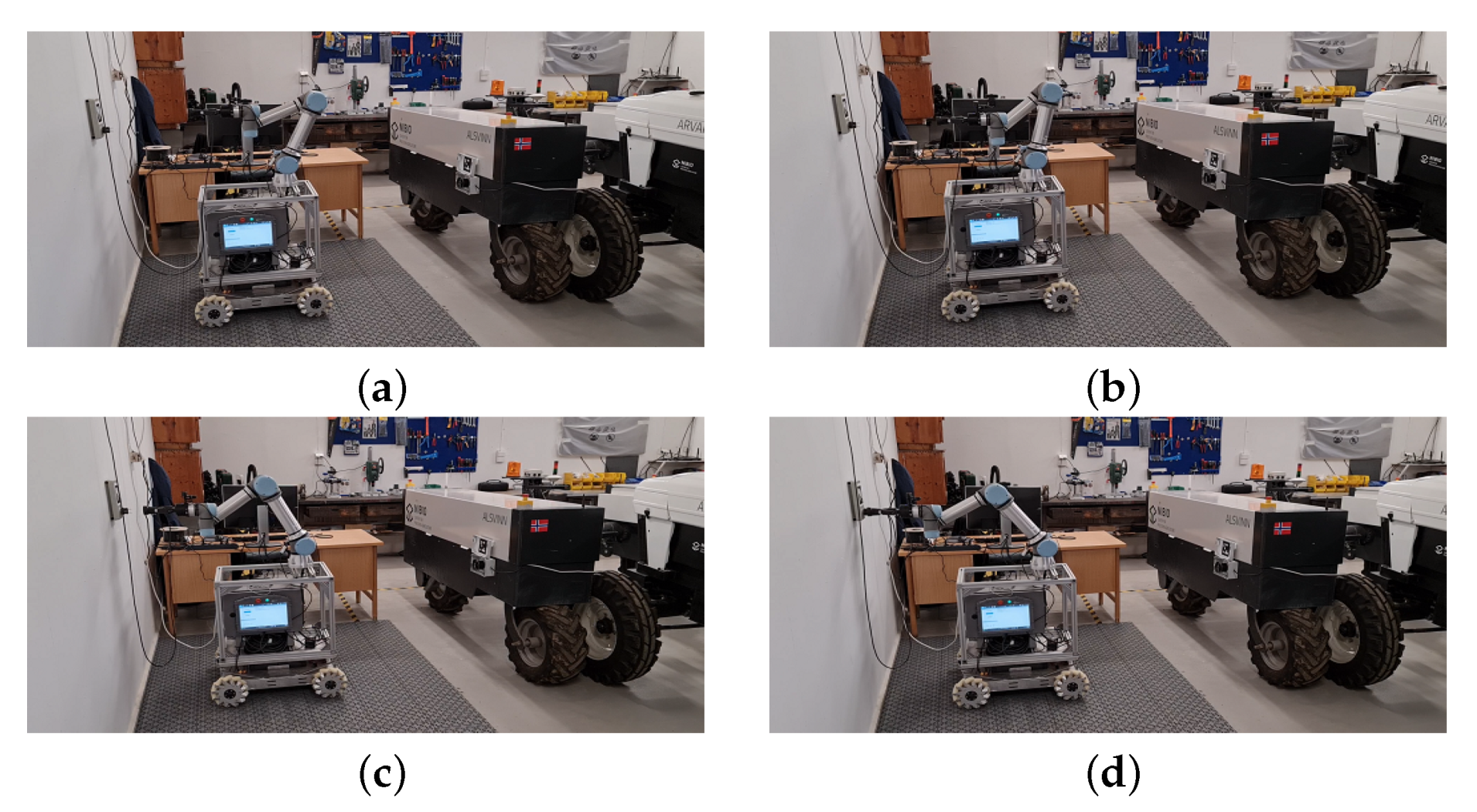
Applsci 11 06168 i001

3. Results

The developed platform was tested under a real-world scenario. The experimental setup consisted of a garage where we parked our electrical vehicle at the Apelsvoll research station (northern Oslo, Norway). The garage has a flat surface that allows the omnidirectional ACS to move freely on its 2D plane. The AEV used for the test is a differential drive electrical tractor robot prototype produced by the Danish company AgroIntelli (Figure 11).
The experimental setup was carried out the with AEV parked at a fixed position at all times. However, for each experiment, the ACS was positioned at a different (and random) pose and orientation facing the wall-plug (as long as its representative fiducial marker is in the ACS camera field-of-view). We carried out more than ten successful experiments, with only one failure that was due to an error of the pose estimation of the marker on the vehicle (the vision node crashed for unknown reasons). The parameters used during the experiments are given in Table 1:
Initially, the ACS robot arm is facing the wall plug (Figure 12a). When a charge request received? condition is true (the AEV sends a charge request to the ACS through a websocket), the charging process begins. The first sequence, as explained in the decision-tree scheme (Figure 5), is to align the MP to the wall-plug (Figure 12b).
Now that the ACS is aligned to the wall-plug, the next sequence unplug cable from wall-plug is initiated. To this end, the first step is to align the gripper to the wall-plug reference fiducial marker (Figure 13a). When the gripper is aligned to the reference point, a socket request is sent to the robot arm processing unit to obtain the pose of the gripper in the fixed frame of the robot arm. The next step is to move the gripper to the approach point (Figure 13b). Once the gripper is at the approach point, a new command to move the gripper towards the plug at a slower velocity is sent. When the gripper is at the plug location, it closes to grab the plug (Figure 13c), then moves in the opposite direction to unplug it from the wall-plug (Figure 13d).
The next sequence is to turn the gripper to face the AEV, and initiate the plug cable to vehicle sequence. The first step in this sequence is to turn the robot arm towards the AEV. The gripper is then moved down because the AEV plug (Figure 4b) is located at a lower level than the wall-plug (Figure 14a). The next step is to align the MP to the AEV (Figure 14b). Once the MP is aligned to the AEV, the following steps are performed consecutively: Align the gripper to the AEV fiducial marker (Figure 14c), move the gripper to the approach point (Figure 14d), plug the cable into the AEV (Figure 14e), and finally open the gripper then move back to the waiting position (Figure 14f). It is worth noting that the height of both the wall-plug and the vehicle plug are known, and does not change no matter how the ACS or the AEV are aligned inside the garage. That is why when we turn the robot arm to face the AEV, an additional step is to move if below the known height of the AEV, or up again when it needs to face the wall-plug.
At this point, the AEV is charging its batteries (meanwhile, the ACS can proceed to charge another vehicle if needed). It can monitor in real-time the power level, and compare it to the required level needed to pursue its field tasks (or just wait until the batteries are fully charged). In both cases, when the AEV is finished charging, it sends a websocket request to the ACS asking to unplug the power cable so it can drive out of the garage.
The final sequence starts when the ACS receives a websocket message from the AEV requesting the ACS to remove the charging cable. In the case that the ACS received other charging requests, and the AEV is finished charging and asking for the charging cable to be removed, the first step for the ACS is to align to the AEV, center the gripper to the AEV reference (the fiducial marker), then proceed with removing the cable. In the case of the presented experiment, and for the sake of simplicity, there was no charging requests from other AEVs; therefore, the ACS was on standby mode while the latter was charging. Thus, the first step is to proceed again to the approach position with the gripper being open (Figure 15a). The gripper then closes and unplug the cable (Figure 15b), then the robot arm turns towards the wall-plug to initiate the next sequence to plug the cable back to the wall-plug (Figure 15c,d).
The final sequence is to plug the charging cable back to the wall-plug. Similar to the first sequence, the ACS aligns first its MP to the wall-plug (Figure 16a), then proceeding with the centering step (Figure 16b), moving the gripper to the approach step (Figure 16c), and finally plugging the cable back to the wall-plug (Figure 16d).
Once the final sequence is completed, the robot arm goes back to the initial pose, and the ACS goes into an idle mode waiting for a new charging request (Figure 17).
The communication between the ACS and the AEV cannot be demonstrated using figures, however, it is possible to observe that the AEV light indicator changes between the sequences when watching the video of the whole process. The light indicator blinks red to warn that the plug/unplug process is undergoing. It changes to a blinking orange when charging, and green when charging is completed, and that the ACS is in an idle state.
The successful sequences confirmed the efficiency of the implemented decision-tree-based scheme of the ACS. The experiments also showed that the proposed controllers in this paper behaved as expected when regulating the position of both the MP and the robotic arm to desired waypoints in space.
The video of the experiment can be found online (https://youtu.be/qwU2TFvCi6M accessed on 1 July 2021).

4. Conclusions

We presented, in this paper, the design and implementation of an autonomous charging station (ACS) for agricultural electric vehicles (AEV). A decision-tree-based architecture was used to define the necessary sequences for plugging and unplugging a charging cable from/to the wall-plug, and to/from the AEV. The efficiency of the proposed solution was demonstrated by experimental results, where a tractor robot AEV was used as an example, showing that both the communication between the AEV and ACS, and the deployed control laws to control the difference sequences for the plug/unplug requests satisfied their objectives. The next step for this work is to generalize the test to multiple vehicles that may come simultaneously for their batteries to be charged. Task allocation, priority list, and multi-vehicle communication schemes will be investigated in order to enhance further the findings in the current paper.

Funding

The work presented in this paper was part of the project SOLARFARM, funded by the Norwegian Research Council (program “Lavutslipp 2030”, project No. 280390).

Institutional Review Board Statement

Not applicable.

Informed Consent Statement

Not applicable.

Data Availability Statement

Not applicable.

Acknowledgments

The author would like to thank Håvard Johansen Lindgaard for his assistance with assembling the charging station.

Conflicts of Interest

The author declare no conflict of interest.

References

  1. John Deere Future of Farming. Available online: https://www.deere.co.uk/en/agriculture/future-of-farming/ (accessed on 1 July 2021).
  2. Fendt e100 Vario: The Battery-Powered Tractor. Available online: https://www.fendt.com/int/fendt-e100-vario (accessed on 1 July 2021).
  3. Hjelkrem, A.G.R.; Fagerström, J.; Kvalbein, L.; Bakken, A.K. Potential for Replacing Fossil Energy by Local PV Energy for Field and Transport Work in Norwegian Farming; NIBIO Rapport; NIBIO: Norway, OSlo, 2020. [Google Scholar]
  4. Emmi, L.; Gonzalez-de Soto, M.; Pajares, G.; Gonzalez-de Santos, P. New trends in robotics for agriculture: Integration and assessment of a real fleet of robots. Sci. World J. 2014, 2014, 404059. [Google Scholar] [CrossRef] [PubMed] [Green Version]
  5. Cariou, C.; Laneurit, J.; Roux, J.C.; Lenain, R. Multi-robots trajectory planning for farm field coverage. In Proceedings of the 2020 16th International Conference on Control, Automation, Robotics and Vision (ICARCV), Shenzhen, China, 13–15 December 2020; pp. 351–356. [Google Scholar]
  6. Moreda, G.; Muñoz-García, M.; Barreiro, P. High voltage electrification of tractor and agricultural machinery—A review. Energy Convers. Manag. 2016, 115, 117–131. [Google Scholar] [CrossRef]
  7. Aghajanzadeh, A.; Therkelsen, P. Agricultural demand response for decarbonizing the electricity grid. J. Clean. Prod. 2019, 220, 827–835. [Google Scholar] [CrossRef] [Green Version]
  8. Solectrac Climate-Smart Electric Tractors. Available online: https://solectrac.com/ (accessed on 1 July 2021).
  9. Dino Autonomous Vegetable Weeding Robot. Available online: https://www.naio-technologies.com/en/agricultural-equipment/large-scale-vegetable-weeding-robot/ (accessed on 1 July 2021).
  10. Harik, E.H.C.; Guérin, F.; Guinand, F.; Brethé, J.F.; Pelvillain, H. UAV-UGV cooperation for objects transportation in an industrial area. In Proceedings of the 2015 IEEE International Conference on Industrial Technology (ICIT), Seville, Spain, 17–19 March 2015; pp. 547–552. [Google Scholar]
  11. Calicioglu, O.; Flammini, A.; Bracco, S.; Bellù, L.; Sims, R. The future challenges of food and agriculture: An integrated analysis of trends and solutions. Sustainability 2019, 11, 222. [Google Scholar] [CrossRef] [Green Version]
  12. Romanov, A.M.; Tararin, A.A. An Automatic Docking System for Wheeled Mobile Robots. In Proceedings of the 2021 IEEE Conference of Russian Young Researchers in Electrical and Electronic Engineering (ElConRus), St. Petersburg, Russia, 2021; pp. 1040–1045. [Google Scholar]
  13. Martinez-Gomez, J.; Fernandez-Caballero, A.; Garcia-Varea, I.; Rodriguez, L.; Romero-Gonzalez, C. A taxonomy of vision systems for ground mobile robots. Int. J. Adv. Robot. Syst. 2014, 11, 111. [Google Scholar] [CrossRef] [Green Version]
  14. Rao, M.S.; Shivakumar, M. IR Based Auto-Recharging System for Autonomous Mobile Robot. J. Robot. Control JRC 2021, 2, 244–251. [Google Scholar]
  15. Zhang, X.; Li, X.; Zhang, X. Automatic Docking and Charging of Mobile Robot Based on Laser Measurement. In Proceedings of the 2021 IEEE 5th Advanced Information Technology, Electronic and Automation Control Conference (IAEAC), Chongqing, China, 12–14 March 2021; Volume 5, pp. 2229–2234. [Google Scholar]
  16. Kim, M.; Chong, N.Y. RFID-based mobile robot guidance to a stationary target. Mechatronics 2007, 17, 217–229. [Google Scholar] [CrossRef]
  17. Volkswagen Electrifying World Premiere: Volkswagen Offers First Glimpse of Mobile Charging Station. Available online: https://www.volkswagen-newsroom.com/en/press-releases/electrifying-world-premiere-volkswagen-offers-first-glimpse-of-mobile-charging-station-4544 (accessed on 1 July 2021).
  18. EVAR Autonomous Charging Robot by Samsung. Available online: https://www.evar.co.kr/eng/ (accessed on 1 July 2021).
  19. CARL Mobile Charging Robot. Available online: https://insideevs.com/news/410418/aiways-mobile-charging-robot-carl-patents/ (accessed on 1 July 2021).
  20. Type F Schuko Plug. Available online: https://www.worldstandards.eu/electricity/plugs-and-sockets/f/ (accessed on 1 July 2021).
  21. Quigley, M.; Conley, K.; Gerkey, B.; Faust, J.; Foote, T.; Leibs, J.; Wheeler, R.; Ng, A.Y. ROS: An open-source Robot Operating System. In Proceedings of the ICRA Workshop on Open Source Software, Kobe, Japan, 17 May 2009; Volume 3, p. 5. [Google Scholar]
  22. Chitta, S.; Sucan, I.; Cousins, S. Moveit![ros topics]. IEEE Robot. Autom. Mag. 2012, 19, 18–19. [Google Scholar] [CrossRef]
  23. Usb Cam ROS Package. Available online: http://wiki.ros.org/usb_cam (accessed on 1 July 2021).
  24. Fiducial Markers ROS Package. Available online: http://wiki.ros.org/aruco_detect (accessed on 1 July 2021).
  25. Rosserial Python ROS Package. Available online: http://wiki.ros.org/rosserial_python (accessed on 1 July 2021).
  26. Joystick ROS Package. Available online: http://wiki.ros.org/joy (accessed on 1 July 2021).
  27. Socket Low-Level Networking Interface. Available online: https://docs.python.org/3/library/socket.html (accessed on 1 July 2021).
  28. Ur5 Client Interfaces. Available online: https://www.universal-robots.com/articles/ur/interface-communication/overview-of-client-interfaces/ (accessed on 1 July 2021).
  29. Python ROS Bridge Library. Available online: https://roslibpy.readthedocs.io/ (accessed on 1 July 2021).
  30. Rosbridge Suite ROS Package. Available online: http://wiki.ros.org/rosbridge_suite/ (accessed on 1 July 2021).
  31. Romero-Ramirez, F.J.; Muñoz-Salinas, R.; Medina-Carnicer, R. Speeded up detection of squared fiducial markers. Image Vis. Comput. 2018, 76, 38–47. [Google Scholar] [CrossRef]
  32. Freund, Y.; Mason, L. The alternating decision tree learning algorithm. In Proceedings of the Sixteenth International Conference on Machine Learning, Bled, Slovenia, 27–30 June 1999; Volume 99, pp. 124–133. [Google Scholar]
  33. Siegwart, R.; Nourbakhsh, I.R.; Scaramuzza, D. Introduction to Autonomous Mobile Robots; MIT Press: Cambridge, MA, USA, 2011. [Google Scholar]
  34. Muir, P.F.; Neuman, C.P. Kinematic modeling of wheeled mobile robots. J. Robot. Syst. 1987, 4, 281–340. [Google Scholar] [CrossRef]
  35. Garrido-Jurado, S.; Muñoz-Salinas, R.; Madrid-Cuevas, F.J.; Marín-Jiménez, M.J. Automatic generation and detection of highly reliable fiducial markers under occlusion. Pattern Recognit. 2014, 47, 2280–2292. [Google Scholar] [CrossRef]
Figure 1. The Autonomous Charging Station composed of: A collaborative robot arm equipped with a gripper and an RGB camera, an aluminum frame, and an omnidirectional mobile platform.
Applsci 11 06168 g001
Figure 2. Global hardware architecture of the Autonomous Charging Station.
Applsci 11 06168 g002
Figure 3. Global software architecture of the Autonomous Charging Station.
Applsci 11 06168 g003
Figure 4. The plugs. (a) The wall-plug that hosts the power-outlet. (b) The vehicle plug.
Applsci 11 06168 g004
Figure 5. The decision-tree scheme of the ACS.
Applsci 11 06168 g005
Figure 6. A mecanum wheel used on the ACS.
Applsci 11 06168 g006
Figure 7. A lateral motion example of an omnidirectional UGV.
Applsci 11 06168 g007
Figure 8. Center gripper taking the fiducial marker as a visual reference.
Applsci 11 06168 g008
Figure 9. Move gripper to the approach waypoint.
Applsci 11 06168 g009
Figure 10. Plugging in the cable.
Applsci 11 06168 g010
Figure 11. The AEV used in the experimental setup. It has a payload of a maximum of 750 kg. It is equipped with a three-point mount system similar to the one used by conventional tractors, which allows for a multi-purpose utilization. Eight 12 V batteries power the UGV. It has hydraulic actuators linked to the three-point hitch, that allow it to fold and unfold the fertilizer applicator arms that can be mounted on the back of the vehicle. The AEV runs on ROS, and can communicate via websockets with the ACS.
Applsci 11 06168 g011
Figure 12. Sequence 1: aligning the ACS to the wall-plug. (a) Seq 1.1: The ACS at the initial position. (b) Seq 1.2: The ACS aligned to the wall-plug.
Applsci 11 06168 g012
Figure 13. Sequence 2: Unplug the cable from the wall-plug and initiate next sequence. (a) Seq 2.1: Align the gripper to the wall-plug fiducial marker. (b) Seq 2.2: Move the gripper to the approach point. (c) Seq 2.3: Close the gripper to unplug the cable from the wall-plug. (d) Seq 2.4: Unplug the power cable from the wall-plug.
Applsci 11 06168 g013
Figure 14. Sequence 3: Plug the cable into the AEV. (a) Seq 3.1: Turn the robot arm, then move the gripper down to face the AEV. (b) Seq 3.2: Align the ACS to the AEV. (c) Seq 3.3: Align the gripper to the AEV fiducial marker. (d) Seq 3.4: Move the gripper to the approach point. (e) Seq 3.5: Plug the cable to the AEV. (f) Seq 3.6: Open the gripper then move back to the waiting position.
Applsci 11 06168 g014
Figure 15. Sequence 4: Unplug the cable from the AEV. (a) Seq 4.1: Move the gripper to the approach point. (b) Seq 4.2: Close the gripper and move back to unplug the cable. (c) Seq 4.3: Turn the robot arm to face the wall-plug. (d) Seq 4.4: Face the wall-plug and initiate next sequence.
Applsci 11 06168 g015
Figure 16. Sequence 5: Plug the cable back into the wall-plug. (a) Seq 5.1: Align the MP to the wall-plug. (b) Seq 5.2: Align the gripper to the AEV fiducial marker. (c) Seq 5.3: Move the gripper to the approach point. (d) Seq 5.4: Plug the cable back to the wall-plug.
Applsci 11 06168 g016
Figure 17. The ACS is back to an idle mode waiting to receive a new charging request through websocket from another AEV.
Applsci 11 06168 g017
Table 1. Experimental parameters.
ParameterSignificanceValues
k l positive linear gain0.5
k a positive angular gain0.15
d A E V distance to the AEV0.5 m
d w a l l p l u g distance to the wall-plug0.4 m
Publisher’s Note: MDPI stays neutral with regard to jurisdictional claims in published maps and institutional affiliations.

