Abstract
In recent years, the advent of the latest-generation technologies and methods have made it possible to survey, digitise and represent complex scenarios such as archaeological sites and historic buildings. Thanks to computer languages based on Visual Programming Language (VPL) and advanced real-time 3D creation platform, this study shows the results obtained in eXtended Reality (XR) oriented to archaeological sites and heritage buildings. In particular, the scan-to-BIM process, digital photogrammetry (terrestrial and aerial) were oriented towards a digitisation process able to tell and share tangible and intangible values through the latest generation techniques, methods and devices. The paradigm of the geometric complexity of the built heritage and new levels of interactivity between users and digital worlds were investigated and developed to favour the transmissibility of information at different levels of virtual experience and digital sharing with the aim to archive, tell and implement historical and cultural baggage that over the years risks being lost and not told to future generations.
1. Introduction
In the last few years, the construction sector has benefited from the advent of the latest generation techniques, methods and tools in the fields of 3D survey, modelling, visualisation and computer graphics. The results obtained from a scientific methodological approach based on integrating the 3D survey, digital photogrammetry with the building information modelling (BIM) allowed professionals to define a new research-oriented field to manage and preserve heritage buildings and archaeological sites [1]. This approach, known as the scan-to-BIM process, used applied research capable of addressing and solving various technical, information technology (IT) and operational problems for the digital management of complex artefacts such as monuments, castles, infrastructures and churches [2,3,4,5]. Heritage buildings from a strictly geometric, metric, and informative perspective are characterised by complex architectural and structural elements that cannot be represented appropriately through the leading BIM software such as Autodesk Revit and Graphisoft Archicad. This first obstacle has now been overcome for some years both from the typological and morphological perspectives. Interesting studies [6,7,8,9] have integrated and automated the digitisation process of artefacts of high historical and cultural value thanks to the development of scan-to-BIM modelling requirements, methods and techniques capable of maintaining the bidirectional information–object relationship within the BIM project.
Consequently, applied research in this specific context has shown how to orient and implement the BIM process for artefacts that require the transmission of different information compared to new buildings [10,11,12]. In particular, heritage building information modelling (HBIM) projects has made it possible to archive, compute, map and share different types of information connected to digital models such as material, historical and decay analyses to improve the conservation and preservation process of the artefact [13,14,15]. Computing, information mapping and sharing were determining factors to understand the main differences compared to CAD vector representations that have characterised the architectural representation in the last three decades [16,17]. Given these three factors, consequently, the term interoperability linked to digital models became a very active field of development and research [3,11,18,19,20]. The development of exchange schemes and formats (proprietary and open) such as DWG, IFC and FBX have been improved to enhance the transmission of information, enhance the dialogue between the main post-processing, modelling and BIM software.
On the other hand, in recent years, the advent and implementation of open platforms oriented towards eXtended Reality (XR) have opened a new path of IT development that can also be followed by architects, engineers and professionals in the construction sector in general. Furthermore, the growing need to share information in increasingly innovative, intelligent and direct forms such as Virtual and Augmented Reality (VR-AR) has led to the launch of a new phase of research and development. Some studies [14,21,22] have shown how professionals can increase the usefulness of HBIM models and the scan-to-BIM process through computer languages such as the Visual Programming Language (VPL). For those reasons, this article summarises the results and developments oriented to creating XR projects based on new forms of human–computer interaction, data collection, scan-to-BIM process and digital photogrammetry for the Church of San Valentino, Siusi, Italy.
The article deals with and analyses in a first phase an updated state of the art in the field of HBIM and XR. The authors deepen both from the theoretical and practical point of view Virtual Reality (VR) and Augmented Reality (AR) oriented to the sharing of information in the field of built heritage. In a second part, the methodological approach applied is described to show how the latest generation tools and methods can be used in synchronous mode to improve the transmissibility of geometric, historical and cultural information of any element from the scan-to-BIM process up to the most advanced forms of XR. Finally, the last paragraphs discuss in holistic terms the results and possible future developments and application uses of the following method in the field of digital cultural heritage (DCH) [23,24,25].
2. Motivation and Main Contributions
This article proposes a method to improve the human–computer interaction between HBIM models and advanced XR projects. The authors investigate, develop and present a digital process capable of transmitting and sharing the tangible and intangible values of the built heritage between different software (open- and closed-source), devices and exchange formats in the most sustainable way possible from an IT point of view while maintaining high levels of parametricity, interoperability, orientation and virtual interactivity of digital models at the same time. Through the scan-to-BIM process, digital photogrammetry (terrestrial and aerial) and the grades of generation (GOG), it was possible to create complex architectural and structural elements [11,26,27] while maintaining both a high grade of accuracy (GOA) in geometric and metric terms and transmitting high levels of information (LOI) [2,14,20].
As is well known, today, this digitisation process requires high skills in the field of architectural, geomatic and restoration representation. At the same time, thanks to the development of new devices, IT becomes the operational key to improve some processes not yet fully resolved in commercial software oriented to BIM and between the dialogue of complex HBIM projects and open-source XR development platforms.
Furthermore, integrating VR devices and AR applications requires additional computer skills, which determine how digital models are to be transmitted between the various software applications. Accordingly, the ‘synchronisation’ is considered by the authors as the operative key to be able to define a process as sustainable as possible, allowing the professionals in charge of generating digital models to be able to transmit geometric entities, parametric objects, orthophotos and their information in an automatic way to the XR platforms, without having to interrupt the digitisation process of complex historic buildings each time, which until now required the use of different software in a discontinuous way (Figure 1). This process is demonstrated through a unique case study of its kind, the Church of San Valentino in Siusi (Castelrotto, Italy), which presents all the possible difficulties that a professional must face during a scan-to-BIM-to-XR process.
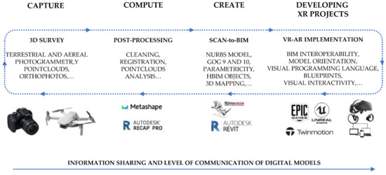
Figure 1.
The proposed digital workflow applied to the research case study.
3. State-of-the-Art
The integration of digital photogrammetry, 3D modelling, HBIM and XR in one digital workflow is opening an entirely new line of research based on the development of reverse engineering processes oriented to the generation of complex buildings in XR environments.
Unmanned aerial vehicles (UAVs) paired with structure-from-motion and photogrammetric workflows have become widely used in different application fields (e.g., mapping, forestry, precision farming, etc.). The possibility of collecting photos collected by different platforms, UAVs and terrestrial, is opening new perspectives to reconstruct Cultural Heritage (CH) sites. The chance of matching UAVs and terrestrial data is connected to the possibility of acquiring oblique images in which the camera axis is intentionally angled ≥ with a 5.0° from nadir. Integration of oblique images into the photogrammetric workflow for mapping complex scenes is not a new issue and has been widely studied for urban applications to obtain complete coverage of both roofs and façade features and elevated elements (e.g., bell towers, etc.). The integration of oblique images and terrestrial images has been widely studied in recent works [28].
Two main approaches are usually employed to process images acquired with different platforms. Image datasets acquired with different platforms are independently processed in the first approach: oriented, georeferenced and dense point clouds are generated. The obtained point clouds are then aligned and merged either by using common ground control points or using cloud-to-cloud solutions like ICP [29].
The main drawbacks of this procedures are misalignment of the clouds, extracted point cloud with different accuracy in the overlapping area, colour and texture mismatch. The second approach processes the images acquired by the various platforms in a combined way. From a theoretical point of view, this solution presents significant advantages with respect to the previous one reducing misalignment issues. However, the final derived results may be quite noisy due to different data resolution and inaccurate matching due to large viewpoint and colour changes. Due to this reason, the definition of optimal workflows for processing oblique UAVs and terrestrial images is still pending. The use of oblique images in UAV–terrestrial photogrammetric workflows and their processing into a unique step has been shown to improve resulting outputs. However, applications in literature are documenting quite large documentation in the optimal workflow both in data acquisition and specifically for oblique camera angles and orientation. This paper will analyse three different workflows using commercial software for oblique and terrestrial image orientation.
On the other hand, the complexity of the structural elements of built heritage needs new advanced methods to simplify the model generation and orient them to new forms of human–computer interaction and XR.
These innovative solutions enabled the management of a significant amount of information also related to HBIM and XR through respect for four holistic requirements:
- Parametricity,
- Interoperability,
- Orientation and
- Virtual interactivity.
As is well known, BIM for heritage buildings (HBIM), favoured the storage and the information sharing of different types of data through tables, graphs, schedules, computing and cost analysis of each part of the building. The main advantage of this modelling approach is the parametricity (first requirement) [3,30]. This requirement of BIM applications aimed at the generation of intelligent digital models with multidimensional connections (building time management) and bidirectional relationship between 3D objects (morphological aspect) and database (typological characteristic), favouring the preservation projects of heritage buildings [29]. Thanks to the parametricity, it was possible to connect a large amount of data and information to each single 3D parametric object, improving the utility and the quality of HBIM models for different purposes [27,31,32]. Therefore, the arduous task of the scan-to-BIM process was to bring a significant amount of data, such as 3D scans, photographs, historical research documents, material and decay analysis, into 3D parametric objects and BIM databases (information mapping) [33,34]. Therefore, overcoming this commercial and informatic gap was necessary to increase the knowledge of digital analysis that required BIM, such as energy analysis, finite element analysis, MEP planning, scheduling, and cost estimation. This concept could be seen as the knowledge related to the concept of interoperability (second requirement) [7,35]. Each type of software needs different kinds of formats, and therefore each BIM needs transfer requirements that allow different levels of interoperability for post-analysis uses [36].
Consequently, it was clear that the quality of a scan-to-BIM model was fundamental at the beginning of the generative process. Furthermore, the orientation (third requirement) itself must be based on new levels of interoperability between different types of software and exchange formats. In this context, it was evident that modelling was the primary factor to be investigated to reduce and manage the gap between model and information sharing [3].
Accordingly, to go beyond an HBIM and represent the architecture in increasingly intelligent and innovative forms capable of interacting with the final users. For this reason, in recent years, research has focused on improving the operational and methodological aspects of HBIM and its metric, historical and cultural value through virtual interactivity (fourth requirement), improving the relationship between models and users [5,37].
In this context, VR is made up of technological and experiential factors capable of bringing the user to new forms of digital experience, going beyond the limits of BIM and other forms of 3D static representations [38,39,40]. Concerning the experiential aspect, VR represents a radical change within the media experience: the subject from the observer of an action becomes the protagonist. VR was born from the idea of “replicating” reality as accurately as possible from a visual, auditory, tactile and even olfactory point of view to perform actions in virtual space overcoming physical, economic and safety limits [40]. The subject is projected into alternative digital worlds, experiencing first- and third-person adventures. Manipulating, seeing, hearing, touching virtual objects, travelling through spaces without a place induces an active interaction process with the virtual world, producing a sense of presence, that is, the sensation of being in the virtual environment. On the other hand, AR is the representation of an altered reality in which virtual/artificial sensory information is superimposed on the ordinary reality perceived through our senses [41]. It is a perceptual enhancement, fundamentally based on the generation of virtual contents by a computer and their superimposition with reality [42].
From a technological perspective, VR consists of a series of tools capable of obtaining information on the subject’s actions (input tools), which are integrated and updated in real-time by the computer to build a 3D world.
Based on the output tools used, it is possible to distinguish three types of VR:
Non-Immersive: determined by a monitor that acts as a “window” through which the user sees the world in 3D; interaction with the virtual world can be done through the mouse, the joystick or other peripherals such as gloves.
Semi-Immersive: determined by rooms equipped with devices and surround rear-projection screens that reproduce the stereoscopic images of the computer and project them on the walls, with different shapes and degrees of convexity, suitable indices of the depth of the image, giving the so-called effect three-dimensional.
Immersive: concerning sound, visualisation, movement and tactile devices (VR headset, gloves and sensory trackers) that isolate the perceptive channels of the subject by immersing him fully, on a sensory level, in the virtual experience he is about to perform. The interaction is given by one or more position sensors (trackers) that detect the subject’s movements and transmit them to the computer so that this can modify the 3D image based on the position and point of view taken by the subject. Although the possibilities of application of this tool and the possible future developments are inspiring, the pressing pace with which virtual reality systems develop, increasing their degree of accessibility each time, brings with it the need to reflect consciously and ethically concerning the possible bad uses that can be made of them because the subjects show very intense reactions in the simulated environments.
Starting from these assumptions, the authors propose a process capable of increasing the usefulness of HBIM models through the implementation of XR projects based on a scan-to-BIM process. The synchronisation of the digitisation phases will be a determining factor for the development of the projects and the transmissibility of the geometric, historical and cultural values of the research case study, laying the foundations for a scalarised application on any type of building, infrastructure or artefact such as the works, jewels and sculptures present in museums and private collections.
4. Method
4.1. The Research Case Study and Its Cultural–Historical Background
The small Church of San Valentino is located in the Northern part of Siusi, on an intense green meadow slope, across the road from the Alpe di Siusi [43,44].
The first documentary mention of this church dates back to the year 1244. In the 14th century, the church was renewed and consecrated again in 1353. A letter of indulgence from the year 1475 mentions further renovations. The present appearance of the building dates back to the beginning of the 16th century because even before 1522 the choir was rebuilt and covered with a vault. These renovation works were supported by large donations from the noble families Wolkenstein and Zwingenstein, who resided in the nearby castles of Hauenstein and Salegg. Their coats of arms are found on the corbels and ribs of the vault. In the years from 1962 to 1972, the frescoes inside the church were discovered and three different layers of the 14th (1st), 15th (2nd) and 16th (3rd) centuries were identified. With the general rehabilitation of the church in 1983, further frescoes could be brought to light. Only the lower part of the bell tower remains of the first building of the church in the 13th century, which rises on the north side of the building. The sacred building has a forepart open to the west, a rectangular nave and a choir with a three-sided termination. The date 1532 is marked on the façade (Figure 2).
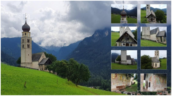
Figure 2.
External views from UAV of San Valentino church, Siusi in Castelrotto, Italy.
Both on the west side and the south side of the church, there were frescoes. To the west, there was a ribbon with depictions of the 14 Helpers. While only the heads are now visible on the left, the four saints on the right side can be identified based on the partially preserved attributes. From left to right, they are S. Barbara (tower), S. Dorotea (basket), S. Caterina (wheel) and S. Margherita (dragon). Above the Annunciation is depicted within a trilobite. The frescoes on the south wall are largely preserved excellently. They show—from west to east—St. Christopher and the Adoration of the Magi. Above the walled-in window, it is possible to see the shroud of Christ. There follows a depiction of the partially destroyed Crucifixion, next to the Madonna enthroned with Child and the patron saint of the Church, S. Valentine of Terni. The lively representation of the figures as well as the attempt to insert them in a representation of the landscape, indicate a master of the Bolzano school, active at the end of the 14th century under strong Veronese influence. The nave is covered by two naves of a reticulated vault, whose ribs at the room’s corners rise from shelves carrying masks. At the top of the vault is a key with the coat of arms of the nobles of Zwingenstein. The other ribs of the vault rest on octagonal servants. A triumphal arch joins the nave and choir. The rib vault in the chorus is clearly better shaped than the one in the nave (Figure 3).
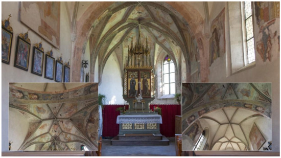
Figure 3.
The vaulted system of the church. Source: F. Dalpiaz.
Only the west and south walls of the nave were frescoed. The most recent layer of 1530 (layer III), very poorly preserved, was detached in 1976, placed on the canvas and placed on the north wall. Below, the frescoes of the 15th century (layer II) were brought to light. In the first span of the south wall, fragments dating back to around 1360 (layer I) could even be found. The cycle of Christ’s stories begins in the east part of the south wall of the nave with the Healing of the woman with a haemorrhage (II), fragments of a teaching scene, the Last Supper, and the Garden Olives. Under the Last Supper (layer II), a representation of St. Christopher (layer I) was brought to light. There is still a scene from the Garden of Olives and Jesus in front of the Sanhedrin (both scenes belonging to layer III). During the 1983 restorations, paintings in the choir were also brought to light. Here are scenes from the Old Testament, from the Creation of Eve to the Original Sin and the Expulsion from Paradise. Above were reproduced scenes from the life of St. Valentine. These paintings date back to the time between 1520 and 1530.
The late Gothic altar currently stands in the church includes a collection of figures in the casket assembled in 1880 by dean Bamhackl. In the middle is the Man of Sorrows with the two saints named Valentine beside him. On the left are the priest and martyr Valentine of Rome, patron saint of lovers, commemorated on February 14 (equivalent to St. Valentine, bishop of Terni). On the right, dressed as a bishop, stands St. Valentine, an itinerant bishop and apostle of Rezia. He is considered a patron against epilepsy. On the inner sides of the doors, there are bas-relief depictions of Mary Magdalene and St. Leonardo. In the closed state, the saints Apollonia, patroness against toothache, and Dorotea are depicted on the doors (Figure 4).
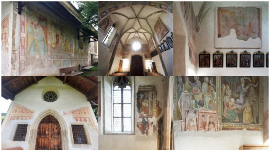
Figure 4.
Frescoes and paintings of the Church. Source: F. Dalpiaz.
Perhaps the construction of the Romanesque bell tower with two orders of mullioned windows and a stretch of perimeter walls dates back to those decades. The bulbous dome above the octagonal drum, which distinguishes this jewel set in the landscape, dates back to 1811. In ancient times the church was also a point of reference for setting boundaries, as evidenced by the border cross on the perimeter wall.
4.2. 3D Survey: Aerial and Terrestrial Photogrammetry of the Church of San Valentino in Siusi, Italy
The first step of the workflow concerns planning of image acquisition. In order to have a complete survey of the area, two different platforms were used: (i) a UAV platform (DJI Mavic Mini) to cover the roof and the bell tower, and (ii) terrestrial acquisition with SM-G975F camera. To guarantee a connection among the terrestrial and the UAV acquisition, oblique images were acquired covering the external facades of the church. A summary with the cameras and acquisition angles is presented in Table 1. The image acquired with the drone was designed to create photogrammetric strips along with the church, guaranteeing a minimum overlap of 70% among the different strips. Terrestrial images were designed as a single strip along the perimeter of the church. The external porch was complemented with additional two strips to cover the timber roof structure.

Table 1.
Church exterior acquisition parameters for the drone and the terrestrial platform.
Image orientation was carried out combined with both terrestrial and drone images by using the software Agisoft Metashape. Due to the main purposes of the work (i.e., generation of a geometric model to be used for VR and XR application) less concern was paid to the metric accuracy of the results. For this reason, no ground control points were used and check points were used to georeference and scale the church. Instead, some manual measurements taken in the church (i.e., main dimensions of the exterior walls, openings, etc.) were used as a scalebar to set up the main dimension of the model properly. Once the images were oriented, the dense matching of the church was carried out by using Agisoft Metashape, subdividing the reconstruction into separate tiles. This choice was adopted to speed up the reconstruction (Figure 5). Indeed, the estimated processing time (process run on an Intel i5 Core with graphic card NVIDIA Quadro T1000) for the whole project was more than 3 days. The subdivision into tiles allowed to process the church in less than 4 h. The indoor of the church was acquired with a standard photogrammetric procedure. Images were acquired in a photogrammetric block using a Sony A7 III (Table 2). The processing was carried out in Agisoft Metashape and also in this case the scaling of the model was carried out by using manual measurements. No connection exists between indoor and outdoor blocks. Due to the aim of the work the positioning of the models was carried out manually using as a reference an existing plan of the church.
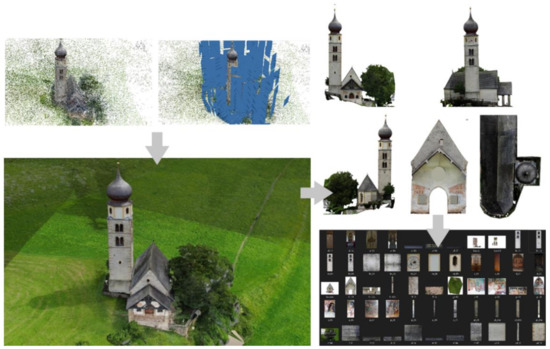
Figure 5.
The mesh textured model and orthophotos obtained using Agisfot Metashape.
Table 2.
Church indoor acquisition parameters.
4.3. The Paradigm of Complexity in Built Heritage and Architecture Representations: From Simple Points to HBIM Objects
Digital 3D survey techniques quickly highlight the shape and dimensions from a morphological and typological point of view. 3D survey aimed to obtain an accurate non-invasive digital data collection, achieving the best point clouds (primary data sources) for each architectural and structural element. A wide variety of types characterises stone and brick vaults, so the importance of constructive techniques has played a key role in the reverse engineering of each architectural component. In addition to laser scanning, the application of advanced photogrammetry techniques also allows the acquisition of the shadow areas of the 3D scans and generates true orthophotos of every single architectural element simultaneously. The building’s components were identified directly in the field thanks to historical documents and 2D drawings (secondary data sources), which completed the interpretive analysis of the building, description of pathologies, and techniques and materials used for the construction. In this context, as is known, at the beginning of the transformation process (from scan to photogrammetric model), point cloud processing applications lead to an automatic generation of mesh models. Software as ContextCapture and Agisoft Metahsape enables the automatic creation of mesh from dense point cloud thanks to specific algorithms that recognise the scan’s point like the data source to generate the mesh’s polygons. Mesh interprets the complexity of the shapes through the union of points through polygons based on different algorithms. This type of model corresponds to a sparse representation of a point cloud in the space. To convert a point cloud in a mesh is similar to creating a significant number of polygons anchoring their vertices to each point of the scan. Figure 6 shows how mesh models of the church try to interpret complex shape using a sparse set of points, converting a point cloud into a significant number of polygons. To perform modelling tests to determine the best scan-to-BIM process found that polygon modelling represents a huge constraint for the model generation and the subsequent management of mesh models in BIM application is not aligned with the software’s logic itself.
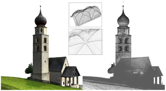
Figure 6.
The mesh models of the church: the main outputs of digital photogrammetry cannot be considered informative models able to share different types of information. They are considered primary data sources as well as point clouds of the proposed method.
Modelling and import tests between free-form software and BIM application found that the mesh model’s physical features represent the main problem for mutual recognition in both applications. In particular, the high number of polygons that try to simulate a continuous curved surface increases the size of the model and obstructs the proper functioning of both software (free-form modelling software and BIM application). For this reason, the studies and tests on generative modelling have considered the mesh as a modelling data source but not a possible output for the implementation of XR projects. In particular, as will be explained in the following paragraphs, the first reason was the impossibility to transform polygonal models in a BIM parametric environment because of their physical features such as size, weight, accuracy, and not smooth shape.
In the last years, to overcome the issues related to mesh modelling, the technique applied to reverse engineering was based on the generation of cutting planes, complex curves, and slices to represent the main characteristics of curved shapes detected by laser scanners and digital photogrammetry. This segmentation of the point clouds is called slicing. The point-cloud segmentation technique has spread rapidly to different types of disciplines, reaching high LOD and creating complex HBIM projects. Slicing requires a proper interpretation of the right point cloud portion and a significant number of slices (curves from scans). Most of the modelling software allowed the segmentation of point clouds through new tools able to obtain the needed slices with 2D cross-section planes. Once the required slices are obtained, the user can follow the slice by manually drawing the generative curves. Accordingly, most 3D modelling for reverse engineering projects is based on slicing, which requires geometric primitives such as B-splines (Figure 7).
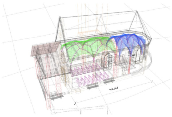
Figure 7.
Extraction of primitives and 3D drawings from primary data sources: the slicing technique applied to the pointclouds and mesh textured model.
On the other hand, BIM technology needs a parametric representation of geometry and not simply a static non-smooth mesh or a semiautomatic B-spline segmentation (2D-3D drawings). The slicing technique and the automatic segmentation have been replaced with novel grades of generations (GOG) to create a model from point clouds. GOG 9 and GOG 10 were fundamental for interpreting and creating complex three-dimensional shapes without manual segmentation and long slicing phases. To understand the benefits and techniques of the applied method the principles and bases of NURBS modelling have been investigated to optimise, finalise and simplify the method for the generation of complex HBIM models. GOGs have been tested and applied on mesh models and dense point clouds to improve the complexity and interactivity of HBIM models and, consequently, support the information mapping and information sharing stages in XR projects.
4.4. Model Generation and Information Mapping
Nowadays, modelling software requires a high knowledge to generate 3D representations capable of communicating various information and numerical values. As briefly mentioned in the previous paragraphs, the creation of geometric elements corresponding to the architectural and structural components of a building allows users to share values such as area, volume, physical and mechanical properties of the materials. At the same time, 3D mapping techniques make it possible to effectively declare the materials used for the construction of the building and provide an appropriate basis for subsequent analyses such as material analysis, identification of historical phases and decay analysis. Thanks to this, it is possible to associate operations, restoration phases, construction sites, and scheduled maintenance at a later stage. The numerical values are associated with actions, moving from an informative 3D representation to a methodological approach capable of supporting the life cycle of the building through shared models, phases, databases, clouds, and many other forms of digital sharing.
Consequently, creating a model must be the most faithful to reality, where the geometric values, the wall partitions and the constructive logic of the building correspond to the real building. For those reasons, the authors’ research in recent years has addressed the paradigm of the complexity of heritage buildings and proposed methods capable of transforming simple points of origin from 3D survey to complex HBIM projects. On the other hand, given the growing need to tell a wider audience the tangible and intangible values of our built heritage, new XR projects have been implemented, requiring specific requirements from the first model generation phase. Thanks to tests and analyses conducted in the digital representation of built heritage, it has been possible to define a sustainable workflow capable of exponentially reducing both the modelling and development phases of HBIM projects for XR environments. As anticipated in the previous paragraph, the modelling phase involved applying the grades of generation GOG9 and GOG 10 defined in an earlier study [3]. In particular, GOG 10 made it possible to automatically transform complex geometric models from 3D surveys into HBIM objects capable of receiving and sharing different types of information. The application of GOG 10 for the Church of San Valentino envisaged, at the basis of the process, the use of the point cloud and the textured mesh model from both terrestrial and aerial photogrammetry. The development of the model involved the following phases:
- Import of point clouds and textured models from digital photogrammetry into NURBS modelling software;
- Integrated application of GOG 9 and GOG 10 for the generation of complex and unique elements such as the complex vaulted system of the church, out-of-plumb walls, structural elements, roof and bell tower;
- Automatic transformation of complex NURBS elements into HBIM objects for the creation and sharing of a BIM project, schedules, two-dimensional drawings;
- Information mapping: insertion of information for each HBIM element created to expand the digital model’s information value.
The model generation phase saw the integrated application of GOG 9 and 10 for the generation of the vaulted system of the Church of San Valentino. Despite being a small building, the church has unique elements of its kind, which required a digitisation process to go beyond the traditional modelling techniques found in BIM software such as Autodesk Revit and Graphisoft Archicad. In particular, the church has two rib vault systems. Rib vaults permitted the construction of much thinner and higher walls and stained glass windows of enormous size, which flooded the cathedrals with light. The rib vault improved upon the earlier Barrel vault, with semicircular arches, widely used by the Romans. An earlier version of the rib vault was used in the 8th century in Islamic Architecture at the Mosque-Cathedral of Cordoba in Moorish Spain.
However, it was decorative, not bearing the structure’s weight. They were also frequently used in later Romanesque and Norman architecture. Beginning in the 11th century, they were used in all of the major Gothic Cathedrals in Europe. Their form gradually changed from a complex sexpartite vault to a simpler but stronger quadripartite vault, allowing much higher cathedrals. By the 13th century, they had again become highly ornamental and complex. The sexpartite vault appeared simultaneously in France and England. The first cathedral to use sexpartite vaults was Durham Cathedral, which begun in 1093. Durham was initially intended to be built with more traditional groin vaults. Early examples of sexpartite rib vaults are found at the Abbaye-aux-Hommes (begun 1066) and Abbaye-aux-Dames at Caen. It then appeared in Noyon Cathedral (begun 1131); the square Gothic porch of the Romanesque Church of Vézelay Abbey in France (1132); Sens Cathedral (begun 1135); the choir of the Abbey of Saint-Denis (begun 1140); Notre-Dame de Paris (begun 1163); Bourges Cathedral; Laon Cathedral. Finally, ribbed vaults were built by William the Englishman at Canterbury Cathedral and in St Faith’s Chapel in Westminster Abbey (1180).
In the vaulted system of San Valentino church, each bay is composed of stone ribs into multiple compartments. The ribs diagonally crossing the structure formed a pointed arch, and there is an intermediate pointed arch, which crossed from side to side. Since the ribs carried the vault’s weight, the panels are made of small pieces of stone and were much lighter than traditional vaults (barrel, groin, etc.). The ribs transmitted the weight downwards and outwards through columns to the piers on the lower level and additional weight of the diagonal traverse arches is supported by massive piers. Since the weight of the vaults is carried by the columns and piers, not the walls, the walls could be higher, and they are filled with more oversized stained glass windows.
Consequently, it is immediate to understand how the geometric complexity of these two structural elements required a scan-to-BIM process capable of respecting the geometric complexity of the elements but at the same time allowed to maintain both high degrees of accuracy (GOA) and levels of detail (LOD) is a sustainable generative process and not too expensive in terms of time and costs related to the modelling itself. For these reasons, the generative method has provided for applying the scan-to-BIM requirements of both GOGs. Following the first phase of identifying the points that define both vaults, the geometric edges of the various components of the vaults were intercepted through automatic extraction and manual 3D drawing. Geometric discretion, at the heart of the scan-to-BIM process and the application of GOG 9 and GOG 10, has made it possible to appropriately identify geometric primitives capable of accurately representing elements such as:
- wedge-shaped pieces called voussoirs which are held in place by the pressure of the neighbouring pieces;
- abutments: a structure to support the lateral pressure of an arch or span;
- imposts: top course of a pillar or a wall that supports the arch;
- intrados: inner curve and surface of an arch or vault;
- estrados: determination of the wall thickness of the vault (through the GOG 10, it is possible to hypothesise the thickness parameter and update it according to subsequent inquiries);
- keystones: the intersection of the ribs of a rib vault. It is structurally important since it marks the apex of the vault;
- diagonal ribs: diagonal elements between two walls to divide a vault into bays. An arch of masonry, often moulded, forms part of the framework on which a vault rests. Ribs generally project from the undersurface of the vault.
Thanks to GOG 10, once the surfaces of the vaults on the intrados were generated through the automatic interpolation of the points of the cloud and of the mesh, it was possible to transform this last time into parametric elements, leaving the pre-established logic of the default BIM libraries which allow the creation of simple elements that are not oriented towards historical buildings. The automatic deformation has allowed to exponentially reduce the modelling phase in the Autodesk Revit software, start the 3D mapping phase, and insert each element’s physical, material, and historical information. Before proceeding with the 3D mapping phase, each generated element was checked from a geometric and metric perspective (AVS). Thanks to the application of an automatic verification system, it was possible to analyse and communicate the model’s reliability [3]. The absence of advanced tools in the BIM software and modelling tools such as the extrusion, the sweep and swept blend, as illustrated in the previous paragraph, do not allow the generation of complex elements characterised by a high number of irregular architectural elements components. The test results laid the foundations for establishing parameters and modelling procedures able to fill this modelling gap. The tests highlighted the possibility of creating HBIM objects without directly modelling it in Autodesk Revit and Graphisoft Archicad, maintaining a high level of interoperability with every type of modelling software (Figure 8). Consequently, before carrying out this transformation from NURBS surfaces to HBIM objects, the surfaces were analysed to improve a system that can certify the model’s quality. For this reason, thanks to the AVS the grade of accuracy (GOA) was calculated and accurately provided the value of the standard deviation between NURBS surface and 3D scan. A quantitative value is provided to quantify the quality of the models produced directly from the acquired point cloud. This provides numerical values representing the standard deviation between point clouds and the whole model without defining parameters’ analysis. This solution is not only an overall indication, but it can be reused to improve model quality over time and, thanks to its direct computation, it results in vast time savings. Finally, the 3D mapping phase made it possible to graphically connote the NURBS model of the church, going beyond the use of generic textures pre-installed in the software architecture. The use and post-production of a large number of orthophotos made it possible to describe every single element materially, identifying areas of decay, materials used, paintings and church furniture elements such as the altar and unique windows such as the rose window above the main entrance and the windows on the south side of the apse area. From an IT point of view, the process involved a mapping technique capable of being automatically recognised by XR development software such as Twinmotion and Unreal Engine. As described in Section 4.5.1, the 3D mapping technique, based on Real-Time Ray Tracing, made it possible to work synchronised with the modelling and mapping phase. The latter started and was controlled in Mc Neel Rhinoceros software and fully recognised in Twinmotion and Unreal Engine. Thanks to using a specific add-in, getting a direct one-click synchronisation of geometry and BIM information from your Revit and NURBS model was possible.

Figure 8.
The scan-to-BIM process applied to the research case study: from digital photogrammetric model (a), NURBS model by GOGs (b), NURBS model (c) to HBIM textured objects (d).
4.5. Information Sharing: Transforming 3D Survey and HBIM Models in XR Projects
Once the 3D mapping phase was completed, it was possible to direct the HBIM model to a subsequent information sharing phase. For the most part, a BIM project requires a high knowledge to interact and understand the information values of each element generated. For this reason, thanks to the application of the main GOGs, it was possible to identify and transfer surfaces and geometric entities such as double curved surfaces, irregular walls, complex wall partitions into elements capable of communicating the physical and mechanical characteristics of some materials.
The next step was to identify the features of the materials and create catalogues capable of storing and sharing textual information and numerical values. Thanks to the HBIM parameter development process, it was possible to develop new descriptive fields, going beyond the basic Autodesk Revit parametric software offer. Thanks to a procedure for implementing BIM parameters and compliance with the bidirectional relationship between object and information, it was also possible to automatically extract schedules and databases of information previously entered in each construction element. Once these types of outputs were generated, it was possible to define new levels of interoperability of the HBIM models with the XR development software.
In particular, the digital flow was supported by the use of new exchange formats capable of appropriately transforming complex architectural and structural elements into static meshes and XR objects ready to accept new forms of IT development and levels of interactivity.
4.5.1. HBIM Interoperability for eXtended Reality (XR): From HBIM Models to Virtual Reality
The need to find forms of VR development capable of creating environments with high LOD, GOA and realistic high-resolution textures led the authors to test a wide range of proprietary and open commercial solutions. Nowadays, most professionals still use highly complex software and spend a lot of time getting realistic settings and simple 3D render images and animations. Thanks to recent developments in computer graphics and VR, it has been possible to go beyond traditional forms of representations of digital models and undertake a development capable of maintaining high levels of interactivity and immersion between the user, machine and developed environment. Thanks to the Twinmotion software that combines an intuitive icon-based interface with the power of Unreal Engine, it has been possible to connect with the major CAD software on the market such as Archicad, Revit, Sketchup Pro and Rhinoceros and animate 3D objects, improving and optimising the textures, accelerating the rendering process reduced to a few seconds and using dynamic elements present within the software library or imported from the main libraries for web objects. Twinmotion was developed by Abvent and then acquired by Epic Games (owner of Unreal Engine) in 2019, becoming the flagship software for Architecture in recent years for the creation of VR environments, 3D animations, renders and panoramas in a completely open logic. The main benefit of this software is the ability to work in complete synchronisation with the leading modelling software and BIM applications. Changes made in modelling software can be synchronised without having to open and close a project each time. Twinmotion is compatible with many 3D formats: 3DS, FBX, SKP, C4D, OBJ and others. Therefore, it can support projects carried out with practically all software currently on the market. In this way, anyone who creates 3D projects can import their works on Twinmotion. Thanks to a wide range of add-ins, the development of the VR project was supported by a modelling and orientation phase of the HBIM model without ever having to close, save and restart the project itself. In this way, it was possible to reduce production times and increase interactivity between the user and the VR project exponentially (Figure 9).
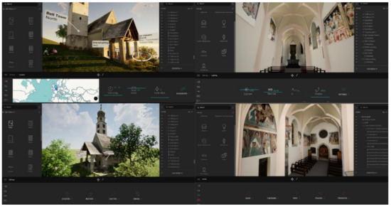
Figure 9.
The VR project of San Valentino church in Twinmotion. On the right external view and on left internal view of the church.
It was found that the Real-Time Rendering available on the market is based on Ray Tracing or a particular calculation technique that allows obtaining realistic lighting of a scene, simulating the physical behaviour of light, taking into account the iterations of the rays produced by one or more light sources with the various objects, before reaching the human eye; this calculation, being very complex, dramatically affects the amount of time taken by the render engine to obtain a photo-realistic final image. The software based on the Unreal Engine engine is called Real-Time Ray Tracing, another image calculation technique that consists of mapping the objects drawn within a scene on a bi-dimensional plane. In particular, through a series of matrices, the information inserted in three dimensions is transformed thanks to an algorithm that determines the colour of each pixel; in this way, the calculation takes place based on the information that is entered and not by calculating the behaviour of the light. Everything is then stored within a mesh which, together with the global lighting of the scene, generates the final render.
The second benefit of this specific logic of development is to take advantage of a real setting. Among the various software innovations, there is the possibility of simulating the seasons and the different environmental climates as long as the digital project is correctly georeferenced concerning the global coordinates: the 2020 version allows varying the time, allowing to change the time of day, thus allowing to obtain a simulation from daylight to authentic night light. In this way, it was possible to insert in the VR project the effect generated by the lights inserted inside the scene, carefully deciding their position and intensity and allowing the final user to perceive not only the geometric context but also the cultural one, the latter decisive for the digital perception of a unique historical and cultural site.
A third benefit was found in 3D mapping. The method proposed and briefly described in the previous paragraph considers a 3D mapping capable of re-elaborating a large number of textures originating from and orthophotos. In this context, the scan-to-BIM process of the San Valentino church includes a post-processing phase capable of transforming simple points into parametric objects. The information value of each 3D object has also been implemented through a mapping capable of maintaining the exact spatial coordinates and 3D geometries previously created in the NURBS modelling software. Consequently, the material connotation of the 3D models through a mapping technique that provided for the timely development of unique textures of their kind involved the following phases: (i) orthophoto production from terrestrial and aerial photogrammetry, (ii) JPG images (including only the geometric extension concerned), adjustment of the RGB values for the VR software, brightness, contrast of every single texture and 3D mapping for non-nonplanar elements. In this context, the 3D mapping provided an automatic update between the Rhinoceros and Twinmotion software. Furthermore, every single modification and 3D mapping procedure was synchronised in real-time with the VR software, taking over the first benefit reported in this paragraph (Figure 10). Finally, the added value of this development logic was found in the interoperability with VR devices.
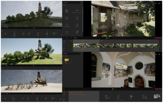
Figure 10.
The level of virtual interactivity of the VR project in Twinmotion allows the user to simulate environmental climates, seasons, lighting, creating 3D animation and discovering information related to the XR objects imported into the scene, such as frescoes and paintings.
Thanks to the development of the VR mode inside the software interface, it is possible to place the end-user in a setting capable of communicating geometric, metric, historical, cultural and environmental values. The user’s interaction with the created 3D reality can take place with different tools such as a mouse, keyboard, joystick, tablet and any other input tool.
In particular, the project in VR mode can support the following devices: Oculus Rift S, Oculus Rift, Oculus Quest 1, Oculus Quest 2, H.T.C. Vive, H.T.C. Vive Pro, H.T.C. Vive Cosmos, H.T.C. Vive Cosmos Elite, Valve Index and Windows MR. Starting from the assumption that VR is a three-dimensional representation produced by the computer similar to reality, the VR project of the Church of San Valentino allowed us to interact with the latest generation VR headsets such as the Oculus Rift and Guest. Therefore, real-time rendering allowed recreating three-dimensional virtual objects and enables the VR to be shown interactively. This is an entirely immersive type of representation in which the user can experience the project, looking at it as if it were already in front of their eyes in real life. The result is greater clarity and unity of purpose between the virtual environment and the user.
The secondary outputs developed and integrated into the VR experience are:
Production of high resolution realistic photographic images: 3D renderings have been developed for indoor and outdoor scenes. The materials are represented in a completely realistic way using a large number of orthophotos. The latter is transformed into textures capable of communicating material aspects that distinguish the body of the building.
Video clips with moving cameras: the rendering engine allows you to create high-resolution video clips to present your projects to customers best. The extra touch can use moving cameras to film indoor and outdoor scenes professionally and at incredible speed or map information panels with documentaries or interactive presentations.
360° panoramas: The plugin has made it possible to produce 360° panoramic images, with the possibility of saving them in an external file or uploading them to the cloud (accessible via a link or QR code). These kinds of images can be viewed on any web browser on both desktop and smartphone and published on social networks. This peculiarity makes it one of the most advanced software thanks to this kind of solution. The integration of 360° panoramas is, moreover, straightforward. Many online services allow you to present better the panoramic images produced and create virtual tours of the projects you are working on. The 360° panoramas are very useful, in any case, because they allow you to recreate a virtual reality despite the use of minimal hardware (such as a smartphone) and at the same time enable non-expert users to view three-dimensional elements without the use of commands, joysticks or non-immediate learning software interface.
A further development phase involved increasing the levels of interactivity between the user and the VR environment. In recent years, thanks to the development of gaming platforms oriented to programming through and visual scripting, it has been possible to increase the information value of HBIM models. As is well known, visual scripting is a Visual Programming Language (VPL) that allows programming through the graphic manipulation of the elements and not through written syntax. A VPL will enable you to program with “visual expressions” and when you need to insert pieces of code (usually, this function is reserved for mathematical formulas). Most VPLs are based on the idea of “boxes and arrows” in which “text boxes” are conceived as functions connected by “arrows”. VPLs can be further classified, depending on how they represent functions on-screen, in icon-based, form-based, or diagramming language. The visual programming environment provides everything you need to “design” a program immediately; concerning written languages, the syntactic rules are practically non-existent. The advantages found through the blueprints (Unreal Engine VPL) are the ease of learning and the ability to view the program status during the debug phases.
Furthermore, parallel programming (if managed by the software) becomes almost “instinctive” and, above all, performed automatically. Blueprints Visual Scripting is based on an interface structured around nodes and allows you to create gameplay elements directly within the Unreal Editor. It is an extremely powerful, easy-to-use system that unfolds the full potential in-game options for video game designers, virtual museums, 3D animations without re-running the code. For this reason, for architects, engineers and professionals in the construction sector, even if they do not possess computer knowledge of programming languages such as C ++, it is possible to give life to the modelled objects and increase their information value by connecting different types of information such as descriptions and multimedia files of all kinds, from video and audio to panoramas, etc. Through Blueprints, the rules of the game were then set and the gameplay conditions changed, creating different variants of interactive virtual objects (IVO), characters and associating them with contents, materials, changing the position of the cameras and their perspective during gameplay, modifying the operation of the control system, managing procedurally generated objects for the scenario.
Therefore, Blueprint is a system built into Unreal Engine 4 that allows you to visually create game scripts by linking nodes, events and functions. The types of Blueprints that were first developed are Level Blueprints and Blueprint Classes, but there are also Blueprint Macros and Blueprint Interfaces (Figure 11).
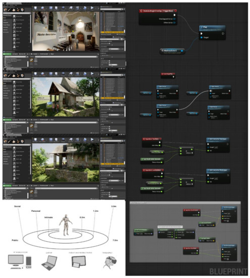
Figure 11.
The main Visual Programming Language (VPL) in Unreal Engine implemented and used for the development of the VR app of the research case study.
Furthermore, for the case study of the Church of San Valentino, it was possible to go beyond the potential offered by the basic architecture of the software, creating and applying a sustainable workflow able to work simulated with Mc Neel Rhinoceros, Autodesk Revit, Twinmotion and Unreal Engine.
Thanks to a completely open development logic, migrating the Twinmotion project to Unreal Engine and increasing the project’s level of interactivity through the VPL. In particular, the user, both in the first and third person and through different devices, can interact with the digitised objects, reading and discovering descriptions and information relating to the paintings of the church, its historical background and the cultural context in which it is situated. Moreover, thanks to the project’s correct georeference, it was possible to tell the surrounding environment in a more interactive form and reach a total immersion where the user, through a VR headset, joystick or keyboard, can freely navigate and interact with IVO. This phase was supported by the development of specific VPLs which can create objects from a scan-to-BIM process (Figure 12). Finally, a further development phase made it possible to increase the level of interactivity of the project to the maximum permitted levels. Thanks to the creation of content associated with a specific QR code, it was possible to connect VR with an AR object library. The implementation phase from VR to AR involved the creation of a library of objects that can be implemented over time, where the end-user, while immersing himself in the VR project, can increase his perception and knowledge of the contents and architectural and structural elements of the church through forms of AR such as mobile and tablet.
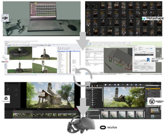
Figure 12.
The level of synchronisation obtained between the various software applications and VR devices.
4.5.2. Augmented Reality for Built Heritage: Towards Augmented Information of Interactive Virtual Object Library
The HBIM approach can be used in AR for many purposes. For example, in the case of the Church of San Valentino, AR tech can serve as a tool that enables the visitors of this place to interact with the church on an immersive level, getting acquainted with the local cultural heritage.
To create an AR experience, one must always prepare the most accurate 3D model possible. Our professional expertise indicates photogrammetry to be the best approach when it comes to choosing the source the 3D models should be built upon. Since the HBIM approach relies on a detailed depiction of a structure, there are multiple rules to follow while the transition of 3D models between an artist and a developer occurs. Such things as Geometry/Topology, 3D Model Scale, 3D Model Centering at Origin, Placement, 3D Model Reset Orientation and Scale Transforms, Scene Organisation, Textures and Materials, Rigging, Source Delivery, and File Formats, Animation should be taken into account.
Moreover, the HBIM approach implies the visualisation of a mathematical model with a vast quantity of data interconnections in it. This abundance of infrastructure inside a model affects its size and makes it a high polygon model. Since most devices with AR capabilities were designed to show low polygon structures, a thorough redrawing of a sophisticated HBIM mesh is in order. In other words, one needs to throw away all unnecessary calculations and over detalisation created by the HBIM approach to put the same model into AR. High polygon meshes require more time to be loaded into the AR.
From our research experience, here are some outtakes of the requirements used for the 3D models to be put in AR:
- Limited amount of poles, at most five edges.
- Polycount for Unity AR: individual model 50K tris max. The whole scene must be 250K tris max.
- The number of materials and textures impact performance significantly more strongly than polycount.
- 3D models should have no extraneous helpers, shapes, splines, or other objects not specifically needed for the model functionality.
- 3D models should include a grouping or hierarchy allowing all objects in the model to be moved together.
Developers use different programs to smoothen the loading as mentioned earlier and automate the whole process in multiple ways. Autodesc is one of them and contains dozens of plugins as well as tools that allow its users to shortcut various sub-processes while the redrawing of an HBIM model takes place.
To increase the level of interactivity and communication of the church, a library of AR objects has been developed for web-based AR apps such as Augmented 3D and Sketchfab, where the user can discover more information on different devices (PCs, mobile phones, tablets). In particular, the developed AR library enables the subject to better visualise some characteristics that would otherwise remain in the background according to the device used (Figure 13).
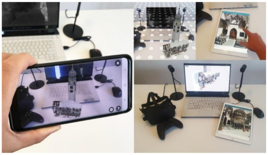
Figure 13.
AR objects developed for a web-based AR platform: user can interact with IVOs and discover different information related to the frescos, painting, decorative apparatus, and architectural and structural element of the church without going directly to the site.
The types of AR developed are:
AR on mobile devices: latest generation smartphone equipped with Global Positioning System (GPS), magnetometer (compass) allowing the visualisation of a video stream in real-time, as well as an Internet connection to receive data online. The smartphone frames the surrounding environment in real-time; content levels are superimposed on the real world, from data from geo-located Points of Interest (POIs) to 3D elements.
AR without markers: the content is the same, but you no longer need to frame any markers. For this reason, this type is more comfortable and usable. It leaves the user freedom of movement. For the insertion of the AR object into the environment, only the first time is required to frame a horizontal plane, for example, the floor, and after a few seconds, the virtual content will appear in position.
5. Discussion
When we talk about BIM, we should speak of a holistic method that allows one to improve different operative and theoretical aspects, from the simple production of drawings to the most advanced building management’s logic. The new era of technologies is defined by developers and computer programming able to support market needs. The open-mindedness between the development and the market needs can encourage the research to create new innovative solutions to enhance the quality of our product, activities and workflows. Thanks to these innovative technological developments, it has been possible to start a phase of development and experimentation in mixed reality (VR-AR), trying to increase the knowledge of information models through a more increased interaction between model, information and user. Generative tests and new immersive environments were developed for the case study of the San Valentino Church, Siusi, (Italy) to increase the sharing of information, laying the foundations for multi-level information environments.
Thanks to the development of new applications such as Twinmotion, Unreal Engine and Unity, it will be possible to automatically migrate the HBIM model into post-production software which, through IT development, will be able to create increasingly interactive virtual environments, increasing, thus, the new paradigm of the utility of BIM also for virtual museums and tourist purposes. An innovative approach is the generation of customised VR objects to exponentially simplify the modelling phase of both the scene and the objects. Thanks to new levels of interoperability between modelling applications, it will be possible to develop more prosperous, more detailed experiences in less time. Table 3 shows the processing times to implement the workflow proposed in Figure 1.
Table 3.
Processing times in relation to the digital tools, software and exchange formats (output–input) to implement the workflow proposed.
Consequently, real-time synchronisation between modelling application and XR development platforms become indispensable factors for the generation of mixed reality experiences (VR-AR) to achieve a strong sense of being presented in a virtual environment enriched by ‘moving’ objects with a high level of contents, details and high resolution textures.
On the other hand, the digital revolution we are witnessing daily requires a continuous and constant update on applications, methods of representation, mapping, and sharing information. BIM is undoubtedly a phenomenon linked to the ongoing progress of IT solutions to support our work and the inclusion of values and information related to a temporal process stratified over time and in culture. For this reason, the definition of technical requirements cannot lead to tangible advantages.
The value of information should be highlighted as much as the model’s accuracy but leaving open the door to future updates and new types of information sharing. Models and methods that simulate the reality will become in everyday use, while the value of built heritage information cannot be contained in a single hub. The proposed method bases the generative process of scan-to-BIM models on the concepts of parametricity, interoperability, orientation and virtual interactivity. Therefore, the centralisation of the BIM process cannot require a single information model but rather the ability to know how to relate in different forms to different types of analyses and uses. Therefore, the approach to these methods, software, and requirements requires specific knowledge and training paths to bring out each potential.
Future developments will be oriented towards the development of new strategies to interact with the model, creating new digital environments able to maximise the experience gathered by the HBIM models and enter into new futuristic digital dimensions where the value of modelling and information will no longer be neglected but will instead become key factors for the investigation of the main international research.
For what concerns the photogrammetry acquisition, further works will be carried out to provide some metric evaluation of the results derived with low-cost sensors both in terms of image parameters (interior/exterior orientation) and quality of the resulting model. Further analysis will involve connecting the indoor and outdoor environment with traditional frame cameras and 360° cameras.
6. Conclusions and Remarks
Floor plans, 3D renderings and HBIM models have always been used to convey a clear idea of how an interior space can be analysed, experienced and inhabited. However, these techniques, perfect on paper, fail to communicate with strength and incisiveness the characteristics of the historical and cultural values linked to the direct discovery of the place. To go beyond the traditional forms of representation and involve the end-user in a real virtual experience with high levels of information and interactivity, it has been decided to implement HBIM models with XR technology in recent years. VR being a purely immersive technology, manages to transport users into a fully interactive 3D environment, allowing them to explore a virtual representation of a particular place, interact with objects and find out if a building, museum or archaeological site can correctly answer all their questions, doubts and curiosities.
For this reason, the case study of the Church of San Valentino made it possible to define a digital method capable of going beyond the scan-to-BIM process, HBIM models and digital photogrammetry. In particular, it was demonstrated that thanks to computer development logics based on visual scripting, it is possible to create static digital models and interact with content with different modes and devices. Thanks to 3D survey and aerial and terrestrial photogrammetry, it was possible to lay the appropriate foundations for the generation of a digital representation with high levels of detail, where the 3D mapping and texturing of objects was favoured by the post-production of orthophotos able to declare the material features of the architectural and structural elements surveyed. The latter was transformed into textures and interactive virtual objects (IVO) and automatically transferred from digital modelling software to XR software.
In particular, the need to maintain and declare the morphological and typological uniqueness of the elements detected allowed us to identify, test and implement a process capable of automatically synchronising complex textured models with software such as Unreal Engine and Twinmotion, thus avoiding the 3D mapping with generic default textures incorporated in the software architecture and immediately pass to the association of complex and straightforward Blueprints.
Thanks to the development of Blueprints, it was shown that an HBIM model derived from digital photogrammetry can come to life in different forms and turn enriched with a large amount of content and information levels, thus allowing an interactive virtual experience remotely or directly on-site through mobile devices. Finally, from the point of view of the interoperability of HBIM models, it was possible to demonstrate how the proposed process is based on the implementation of specific exchange formats, capable in turn of transferring certain geometric, metric and materials to different mobile devices such as tablets and mobile phones.
Tangible and intangible values can thus be shared, discovered and disseminated to the user by developing a real app that can install and orient for different operating systems. In light of this aspect, it was possible to emphasise how new scan-to-BIM-to-XR requirements can be defined in an entirely independent way, trying to achieve specific project objectives by aligning producer and customer through specific qualitative and quantitative parameters.
Author Contributions
Conceptualization, F.B. and M.P.; methodology, F.B. and M.P.; software, F.B. and M.P.; validation, F.B. and M.P.; F.B. and M.P.; investigation, F.B. and M.P.; resources, F.B. and M.P.; data curation, F.B. and M.P.; writing—original draft preparation, F.B. and M.P.; writing—review and editing, F.B. and M.P.; visualization, F.B. and M.P.; supervision, F.B. and M.P.; project administration, F.B. and M.P.; funding acquisition, F.B. and M.P. All authors have read and agreed to the published version of the manuscript.
Funding
This research received no external funding.
Institutional Review Board Statement
Not applicable.
Informed Consent Statement
Not applicable.
Data Availability Statement
Data will be available upon request.
Acknowledgments
The authors would like to express their sincere gratitude the Municipality of Castelrotto and Councillor for culture, Adolf Hofer, for the continuous support during the last year https://www.comune.castelrotto.bz.it/it (accessed on 23 May 2021). A special thanks go to Christoph Gasser, Head of the Civic Museum of Chiusa for the valuable historical information shared in recent months https://www.klausen.eu/de/Gasser_Christoph (accessed on 23 May 2021). The authors thank Fabian Dalpiaz for the crucial support during the terrestrial photogrammetric survey https://www.fabian-dalpiaz.com/ (accessed on 23 May 2021). The authors would like to thank WeAR Studio and BDM Vladyslav Chernykh for their consulting and cooperation in AR implementation https://wear-studio.com/ (accessed on 23 May 2021).
Conflicts of Interest
The authors declare no conflict of interest.
References
- Dore, C.; Murphy, M. Integration of HBIM and 3D GIS for Digital Heritage Modelling. In Proceedings of the Digital Documentation, Edinburgh, UK, 22–23 October 2012. [Google Scholar]
- Brumana, R.; Georgopoulos, A.; Oreni, D.; Raimondi, A.; Bregianni, A. HBIM for documentation, dissemination and management of built heritage. The case study of St. Maria in Scaria d’Intelvi. Int. J. Herit. Digit. Era 2013, 2, 433–451. [Google Scholar] [CrossRef] [Green Version]
- Banfi, F. BIM Orientation: Grades of Generation and Information for Different Type of Analysis and Management Process. Int. Arch. Photogramm. Remote Sens. Spat. Inf. Sci. 2017, 42, 57–64. [Google Scholar] [CrossRef] [Green Version]
- Fai, S.; Sydor, M. Building Information Modelling and the documentation of architectural heritage: Between the ‘typical’ and the ‘specific’. In Proceedings of the 2013 Digital Heritage International Congress (Digital Heritage) IEEE, Marseille, France, 28 October–1 November 2013; Volume 1, pp. 731–734. [Google Scholar]
- Gironacci, I.M. State of the Art of Extended Reality Tools and Applications in Business. In Transdisciplinary Perspectives on Risk Management and Cyber Intelligence; IGI Global: Hershey, PA, USA, 2021; pp. 105–118. [Google Scholar]
- Inzerillo, L.; Lo Turco, M.; Parrinello, S.; Santagati, C.; Valenti, G.M. BIM e beni architettonici: Verso una metodologia operativa per la conoscenza e gestione del patrimonio culturale. DisegnareCon Le Dimens. Del BIM 2016, 9, 161–169. [Google Scholar]
- Chiabrando, F.; Sammartano, G.; Spanó, A.T. Historical Building Models and their handling via 3D survey: From points clouds to user-oriented HBIM. Int. Arch. Photogramm. Remote Sens. Spat. Inf. Sci. 2016, XLI-B5, 633–640. [Google Scholar] [CrossRef] [Green Version]
- Banfi, F.; Chow, L.; Reina Ortiz, M.; Ouimet, C.; Fai, S. Building Information Modeling for Cultural Heritage: The Management of Generative Process for Complex Historical Buildings. In Digital Cultural Heritage; Ioannides, M., Ed.; Lecture Notes in Computer Science; Springer: Cham, Switzerland, 2018; Volume 10605, pp. 119–130. [Google Scholar]
- Diara, F.; Rinaudo, F. From reality to parametric models of cultural heritage assets for HBIM. Int. Arch. Photogramm. Remote Sens. Spat. Inf. Sci. 2019, XLII-2/W15, 413–419. [Google Scholar] [CrossRef] [Green Version]
- Bruno, N.; Roncella, R. A restoration oriented HBIM system for cultural heritage documentation: The case study of Parma cathedral. Int. Arch. Photogramm. Remote Sens. Spat. Inf. Sci. 2018, XLII-2, 171–178. [Google Scholar] [CrossRef] [Green Version]
- Simeone, D.; Cursi, S.; Toldo, I.; Carrara, G. B(H)IM-Built Heritage Information Modelling–Extending BIM approach to historical and archaeological heritage representation. In Proceedings of the 32nd eCAADe Conference, Newcastle upon Tyne, UK, 10–12 September 2014; Volume 1, pp. 613–622. [Google Scholar]
- Costantino, D.; Pepe, M.; Restuccia, A.G. Scan-to-HBIM for conservation and preservation of Cultural Heritage building: The case study of San Nicola in Montedoro church (Italy). Appl. Geomat. 2021, 1–15. [Google Scholar] [CrossRef]
- Bosch, A.; Volker, L.; Koutamanis, A. BIM in the operations stage: Bottlenecks and implications for owners. Built Environ. Proj. Asset Manag. 2015, 5, 331–343. [Google Scholar] [CrossRef]
- López, F.J.; Lerones, P.M.; Llamas, J.; Gómez-García-Bermejo, J.; Zalama, E. Linking HBIM graphical and semantic information through the Getty AAT: Practical application to the Castle of Torrelobatón. In Proceedings of the IOP Conference Series: Materials Science and Engineering, Florence, Italy, 16–18 May 2018; Volume 364, p. 012100. [Google Scholar]
- Pauwels, P.; De Meyer, R.; Van Campenhout, J. Interoperability for the design and construction industry through semantic web technology. In Proceedings of the International Conference on Semantic and Digital Media Technologies 2010, Saarbrücken, Germany, 1–3 December 2010; pp. 143–158. [Google Scholar]
- Roberts, C.J.; Pärn, E.A.; Edwards, D.J.; Aigbavboa, C. Digitalising asset management: Concomitant benefits and persistent challenges. Int. J. Build. Pathol. Adapt. 2018, 36, 152–173. [Google Scholar] [CrossRef]
- Visintini, D.; Marcon, E.; Pantò, G.; Canevese, E.P.; De Gottardo, T.; Bertani, I. Advanced 3d Modeling Versus Building Information Modeling: The Case Study of Palazzo Ettoreo in Sacile (Italy). Int. Arch. Photogramm. Remote Sens. Spat. Inf. Sci. 2019, 42, 1137–1143. [Google Scholar] [CrossRef] [Green Version]
- Terkaj, W.; Šojić, A. Ontology-based representation of IFC EXPRESS rules: An enhancement of the ifcOWL ontology. Autom. Constr. 2015, 57, 188–201. [Google Scholar] [CrossRef]
- Costa, G.; Madrazo, L. Connecting building component catalogues with BIM models using semantic technologies: An application for precast concrete components. Autom. Constr. 2015, 57, 239–248. [Google Scholar] [CrossRef]
- BuildingSMART: Linked DataWorking Group. 2018. Available online: https://technical.buildingsmart.org/standards/ifc/ifc-formats/ifcowl/ (accessed on 3 January 2020).
- Kang, T.; Choi, H. BIM perspective definition metadata for interworking facility management data. Adv. Eng. Inform. 2015, 29, 958–970. [Google Scholar] [CrossRef]
- Allemang, D.; Hendler, J. Semantic Web for the Working Ontologist: Effective Modeling in RDFS and OWL; Morgan Kaufmann: Burlington, MA, USA, 2011. [Google Scholar]
- Brumana, R.; Ioannides, M.; Previtali, M. Holistic heritage building information modelling (HHBIM): From nodes to hub networking, vocabularies and repositories. In Proceedings of the 2nd International Conference of Geomatics and Restoration, GEORES 2019, Milan, Italy, 8–10 May 2019; Volume 42, pp. 309–316. [Google Scholar]
- Niknam, M.; Karshenas, S. A shared ontology approach to semantic representation of BIM data. Autom. Constr. 2017, 80, 22–36. [Google Scholar] [CrossRef] [Green Version]
- Piccoli, E. Volte composte nell’architettura piemontese del Settecento: Le volte planteriane. PALLADIO 1999, VII, 87–100. [Google Scholar]
- Knublauch, H.; Oberle, D.; Tetlow, P.; Wallace, E.; Pan, J.Z.; Uschold, M. A Semantic Web Primer for Object-Oriented Software Developers. W3c Working Group Note, W3C. 2006. Available online: https://www.w3.org/TR/sw-oosd-primer/ (accessed on 3 January 2020).
- Quattrini, R.; Pierdicca, R.; Morbidoni, C. Knowledge-based data enrichment for HBIM: Exploring high-quality models using the semantic-web. J. Cult. Herit. 2017, 28, 129–139. [Google Scholar] [CrossRef]
- Stöcker, C.; Eltner, A.; Karrasch, P. Measuring gullies by synergetic application of UAV and close range photogrammetry—A case study from Andalusia, Spain. Catena 2015, 132, 1–11. [Google Scholar] [CrossRef]
- Besl, P.J.; McKay, N.D. Method for registration of 3-D shapes. In Sensor Fusion IV: Control Paradigms and Data Structures; International Society for Optics and Photonics: Bellingham, WA, USA, 1992; pp. 586–606. [Google Scholar]
- Oreni, D.; Brumana, R.; Georgopoulos, A.; Cuca, B. HBIM for conservation and management of built heritage: Towards a library of vaults and wooden beam floors. In ISPRS Annals of Photogrammetry, Remote Sensing and Spatial Information Sciences; Grussenmeyer, P., Ed.; Copernicus Publications: Göttingen, Germany, 2013; Volume II-5/W1, pp. 215–221. [Google Scholar]
- Altun, M.; Akcamete, A. A method for facilitating 4D modeling by automating task information generation and mapping. In Advances in Informatics and Computing in Civil and Construction Engineering; Springer: Cham, Switzerland, 2019; pp. 479–486. [Google Scholar]
- Brumana, R.; Stanga, C.; Banfi, F. Models and scales for quality control: Toward the definition of specifications (GOA-LOG) for the generation and re-use of HBIM object libraries in a Common Data Environment. Appl. Geomat. 2021, 1–29. [Google Scholar] [CrossRef]
- Brumana, R.; Condoleo, P.; Grimoldi, A.; Landi, A.G.; Attico, D.; Turrina, A.; Banfi, F.; Previtali, M. HBIM Feeding Open Access Vault Inventory Through GeoDB HUB. In Proceedings of the Euro-Mediterranean Conference 2018, Nicosia, Cyprus, 29 October–3 November 2018; pp. 27–38. [Google Scholar]
- Barazzetti, L.; Banfi, F.; Brumana, R.; Previtali, M. Creation of parametric BIM objects from point clouds using NURBS. Photogramm. Rec. 2015, 30, 339–362. [Google Scholar] [CrossRef]
- Chiabrando, F.; Lo Turco, M.; Rinaudo, F. Modeling the decay in an HBIM starting from 3D point clouds. a followed approach for cultural heritage knowledge. Int. Arch. Photogramm. Remote. Sens. Spat. Inf. Sci. 2017, XLII-2/W5, 605–612. [Google Scholar] [CrossRef] [Green Version]
- Cogima, C.K.; Paiva, P.V.V.; Dezen-Kempter, E.; Carvalho, M.A.G.; Soibelman, L. The role of knowledge-based information on BIM for built heritage. In Advances in Informatics and Computing in Civil and Construction Engineering; Springer: Cham, Switzerland, 2019; pp. 27–34. [Google Scholar]
- Ioannides, M.; Magnenat-Thalmann, N.; Papagiannakis, G. Mixed Reality and Gamification for Cultural Heritage; Springer: Cham, Switzerland, 2017. [Google Scholar]
- Lerma, J.L.; Navarro, S.; Cabrelles, M.; Villaverde, V. Terrestrial laser scanning and close range photogrammetry for 3D archaeological documentation: The Upper Palaeolithic Cave of Parpalló as a case study. J. Archaeol. Sci. 2010, 37, 499–507. [Google Scholar] [CrossRef]
- Lo Turco, M.; Calvano, M.; Giovannini, E.C. Data modelling for museum collections. Int. Arch. Photogramm. Remote Sens. Spat. Inf. Sci. 2019, XLII-2/W9, 433–440. [Google Scholar] [CrossRef] [Green Version]
- Jung, K.; Nguyen, V.T.; Lee, J. BlocklyXR: An Interactive Extended Reality Toolkit for Digital Storytelling. Appl. Sci. 2021, 11, 1073. [Google Scholar] [CrossRef]
- Jang, J.; Ko, Y.; Shin, W.S.; Han, I. Augmented Reality and Virtual Reality for Learning: An Examination Using an Extended Technology Acceptance Model. IEEE Access 2021, 9, 6798–6809. [Google Scholar] [CrossRef]
- Pybus, C.; Graham, K.; Doherty, J.; Arellano, N.; Fai, S. New Realities for Canada’s Parliament: A Workflow for Preparing Heritage Bim for Game Engines and Virtual Reality. Int. Arch. Photogramm. Remote Sens. Spat. Inf. Sci. 2019, XLII-2/W15, 945–952. [Google Scholar] [CrossRef] [Green Version]
- Gruber, K. Kunst in der Pfarre Seis am Schlern; Lana Tappeiner: Merano, Italy, 1996; ISBN 88-7073-213-4. [Google Scholar]
- Gleirscher, P.; Nothdurfter, H.; Schubert, E. Das Rungger Egg: Untersuchungen an einem eisenzeitlichen Brandopferplatz bei Seis am Schlern in Südtirol. In Römisch-Germanische Forschungen; DAI: Darmstadt, Germany, 2002; p. 61. ISBN 3-8053-2826-5. [Google Scholar]
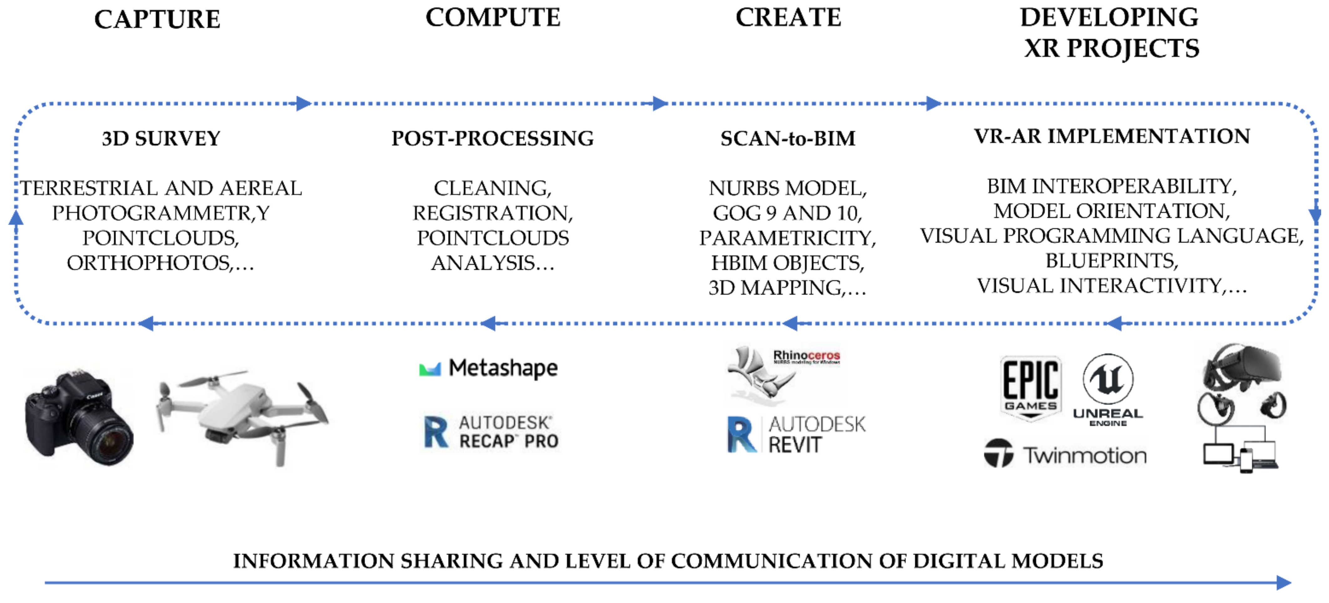
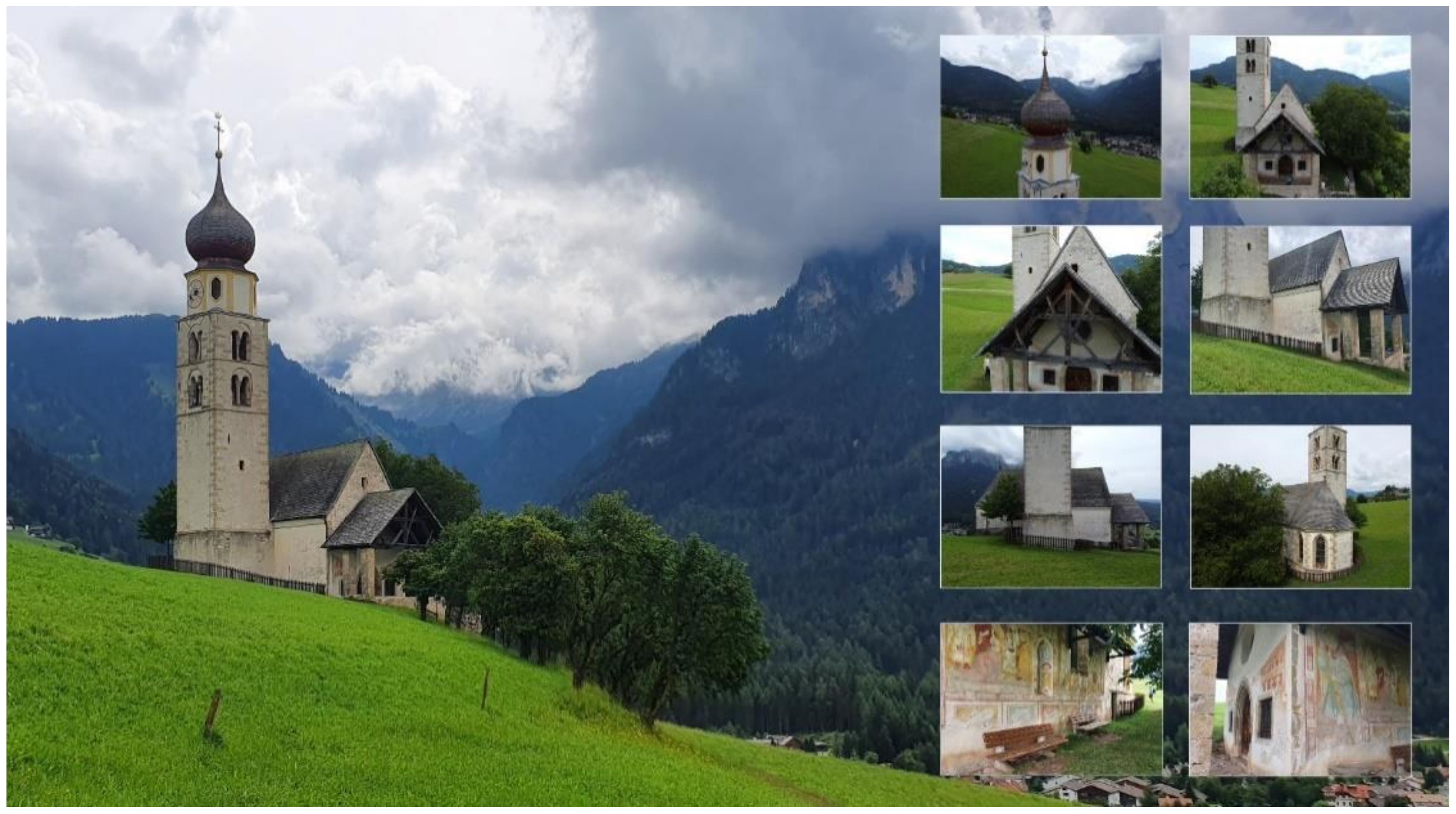
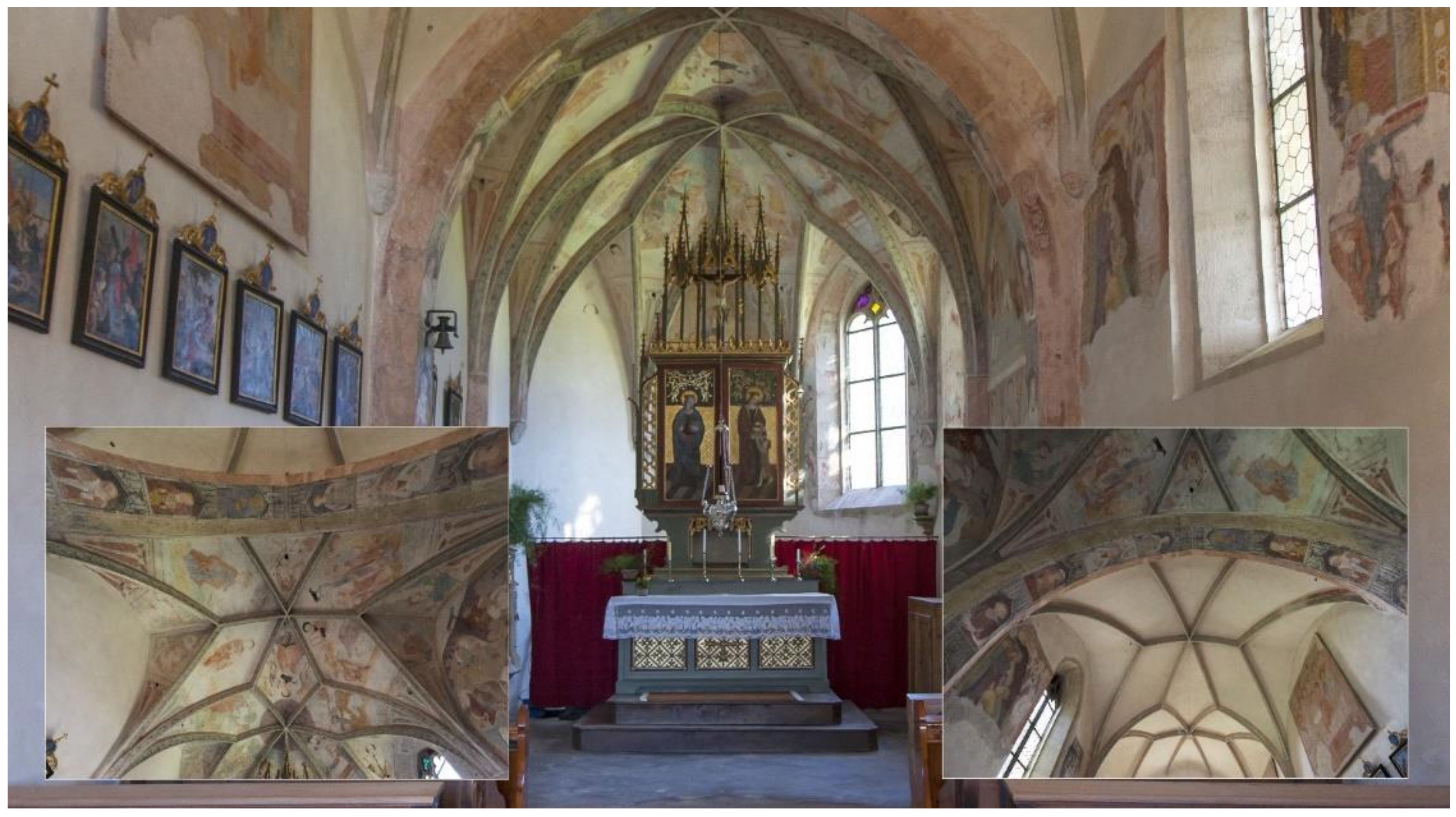
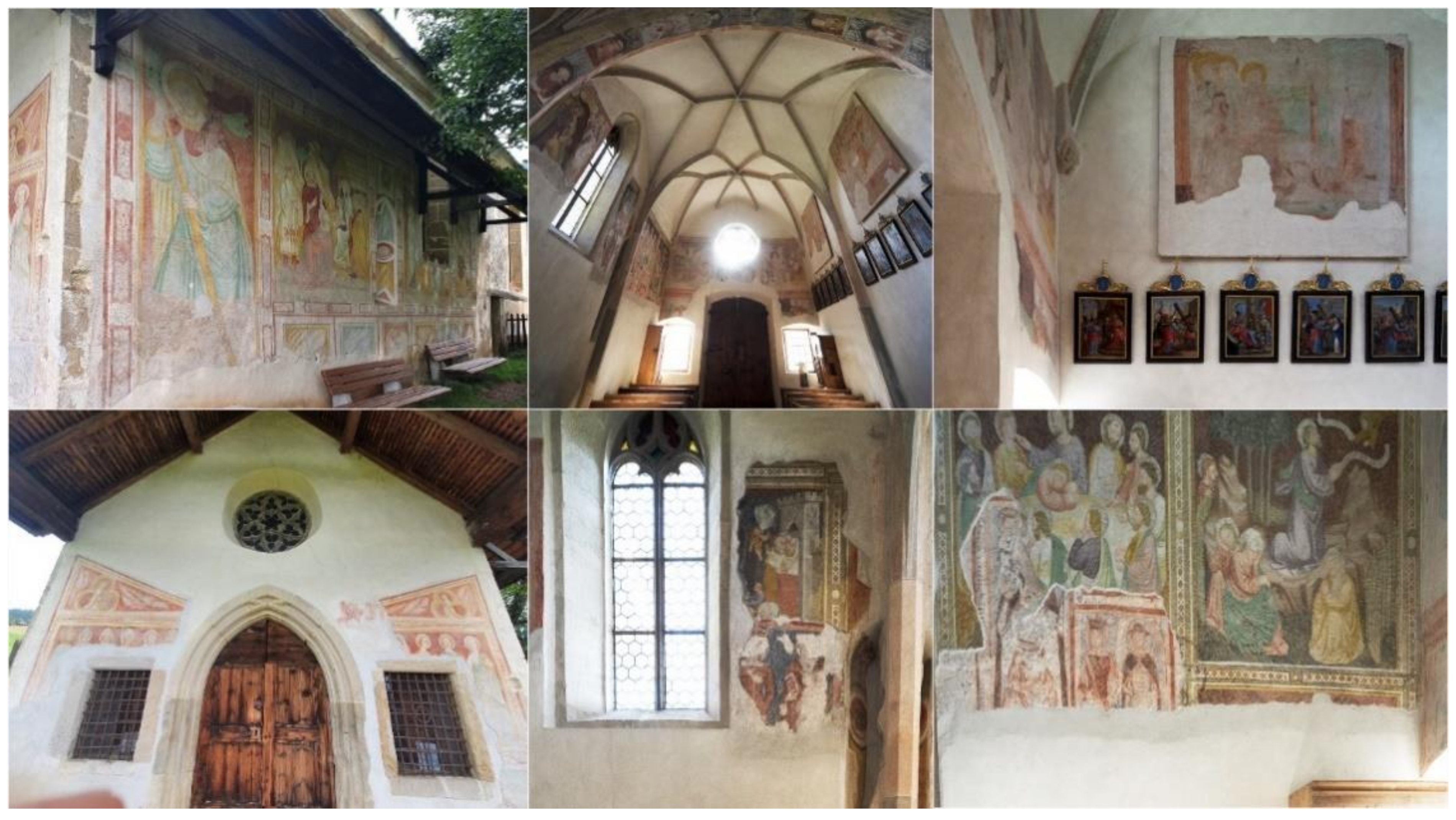
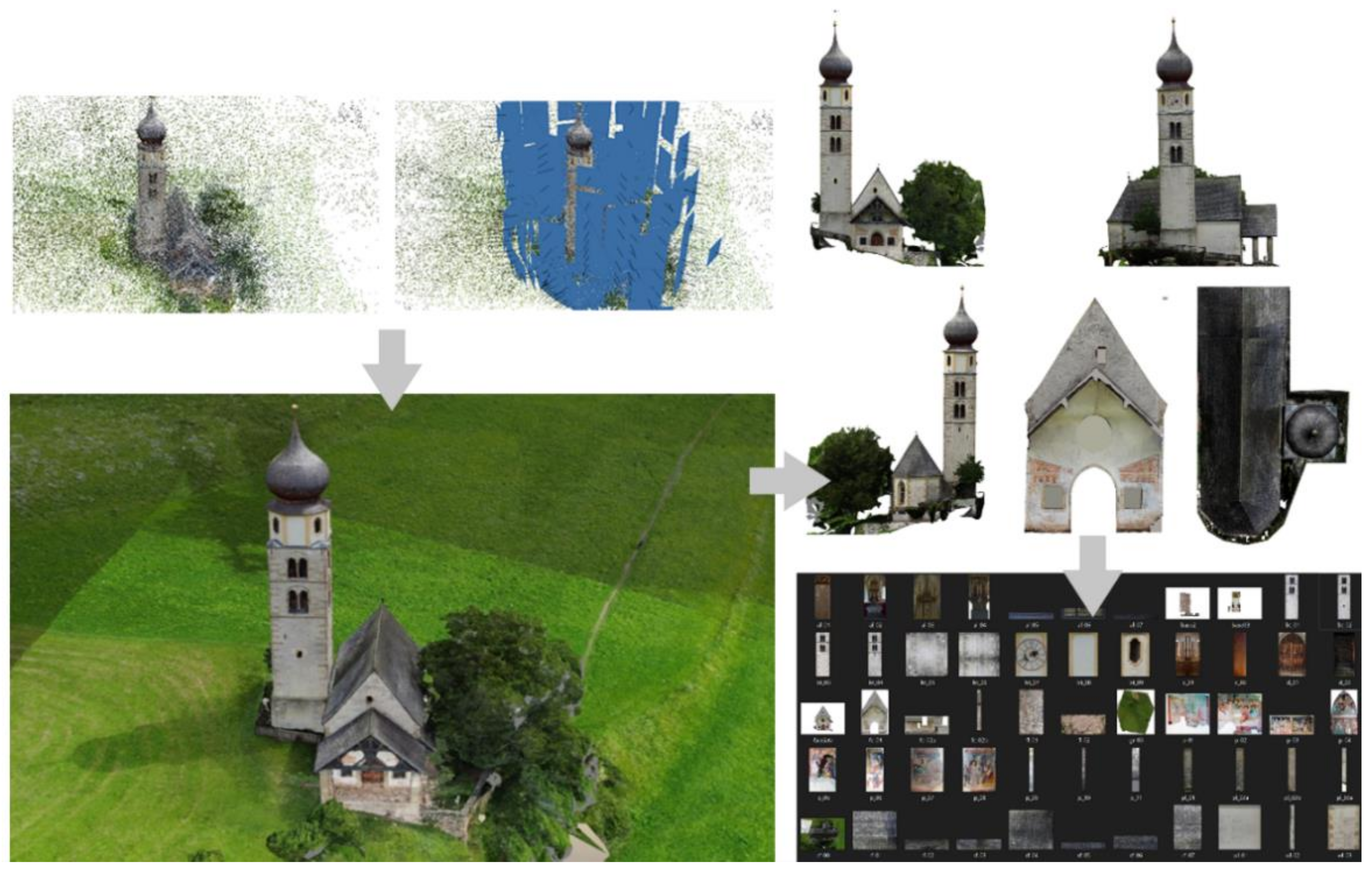
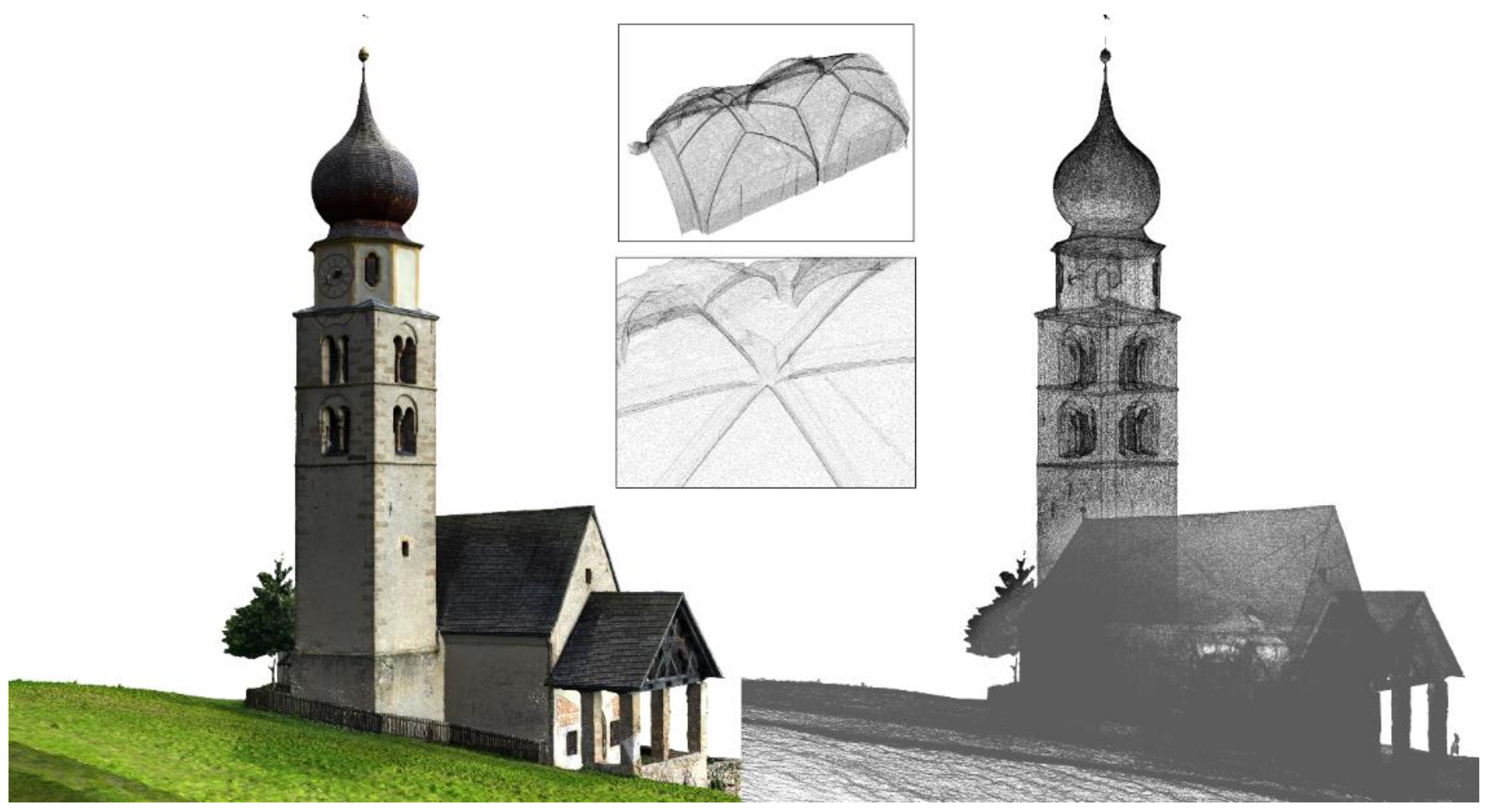
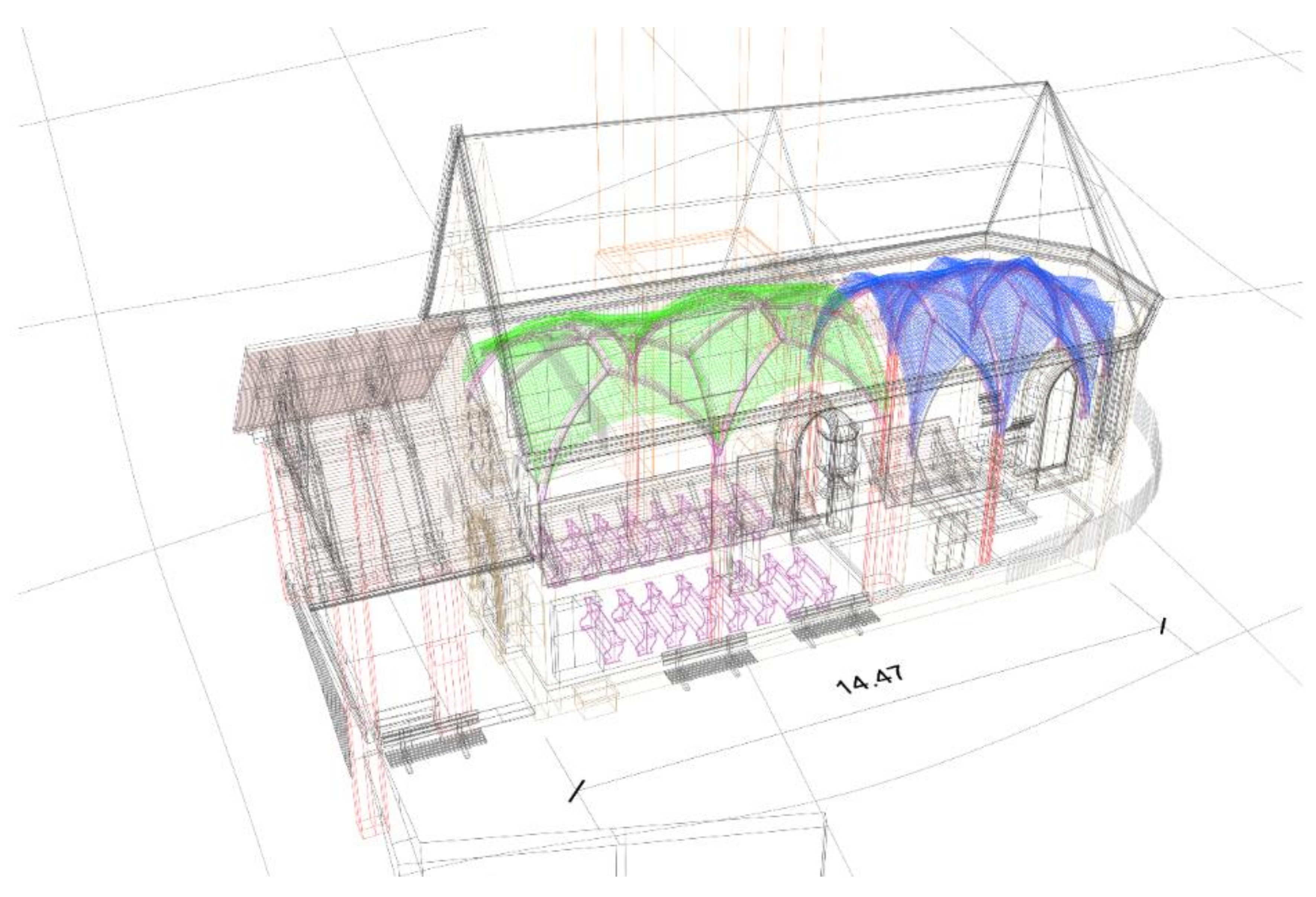
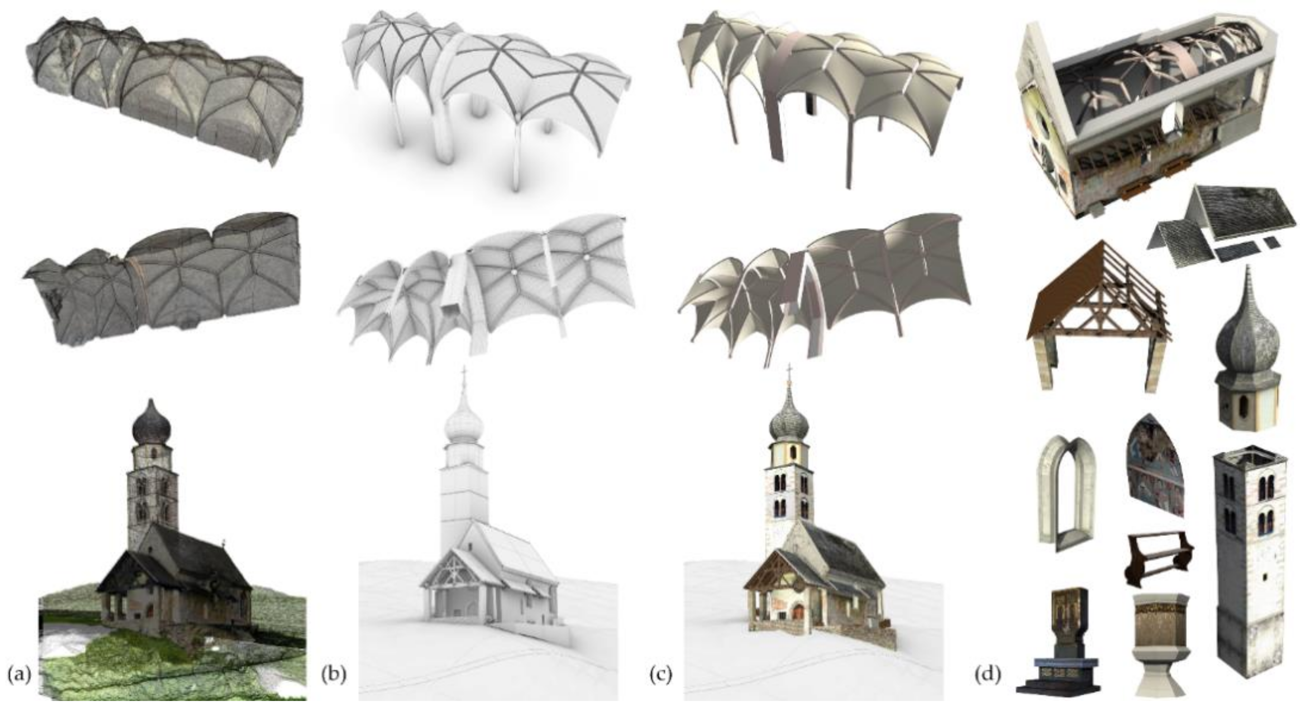
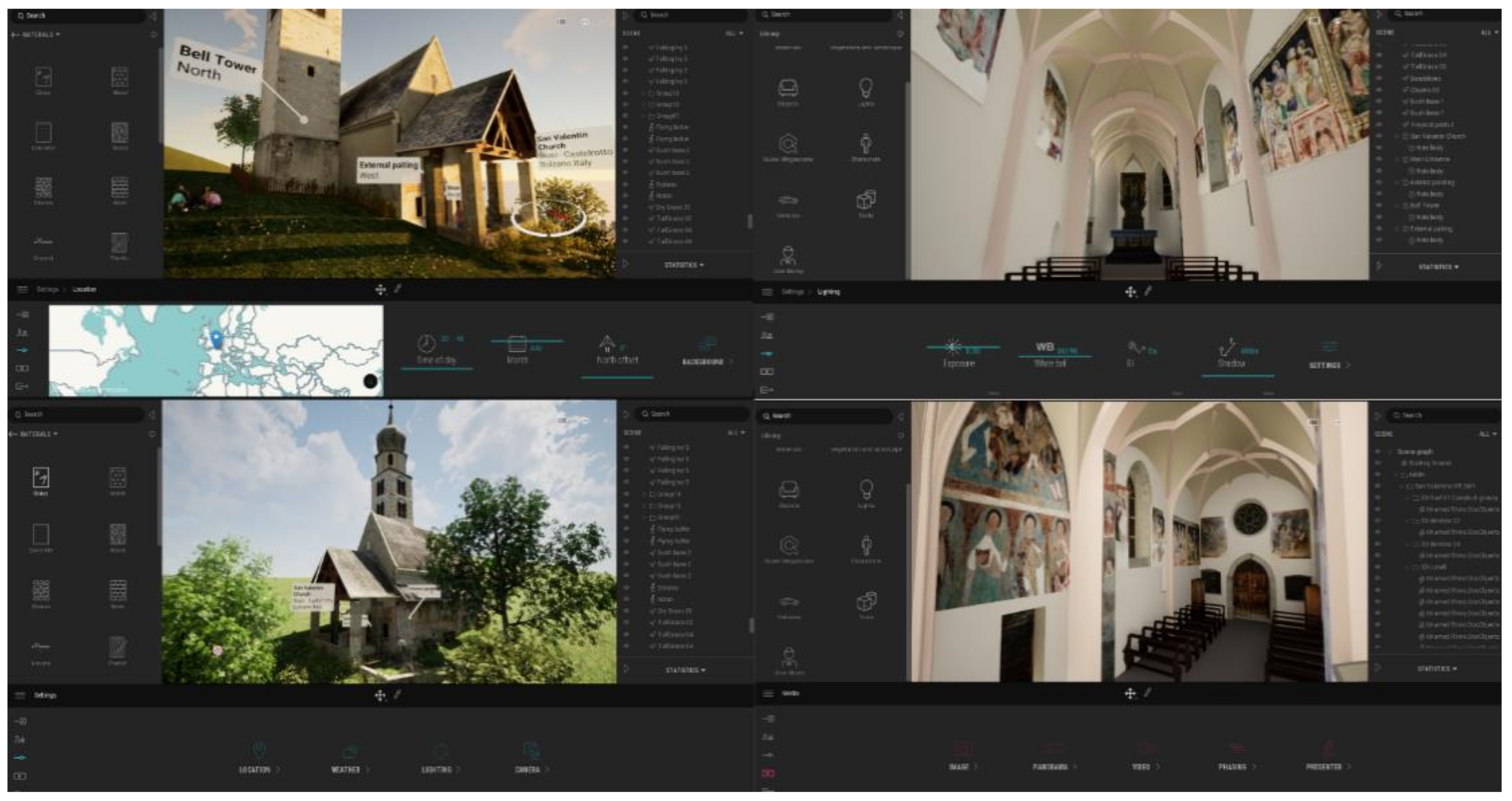
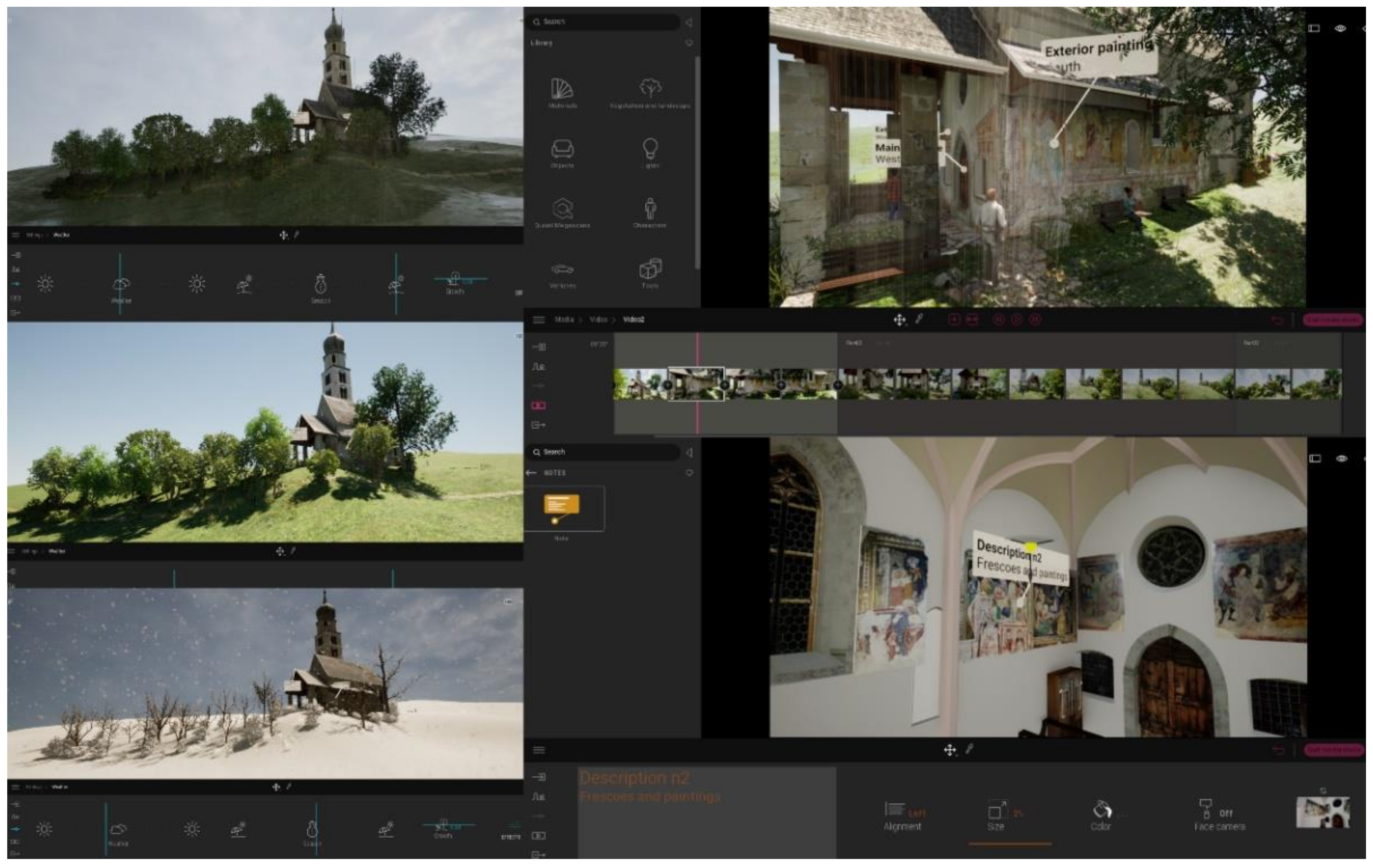
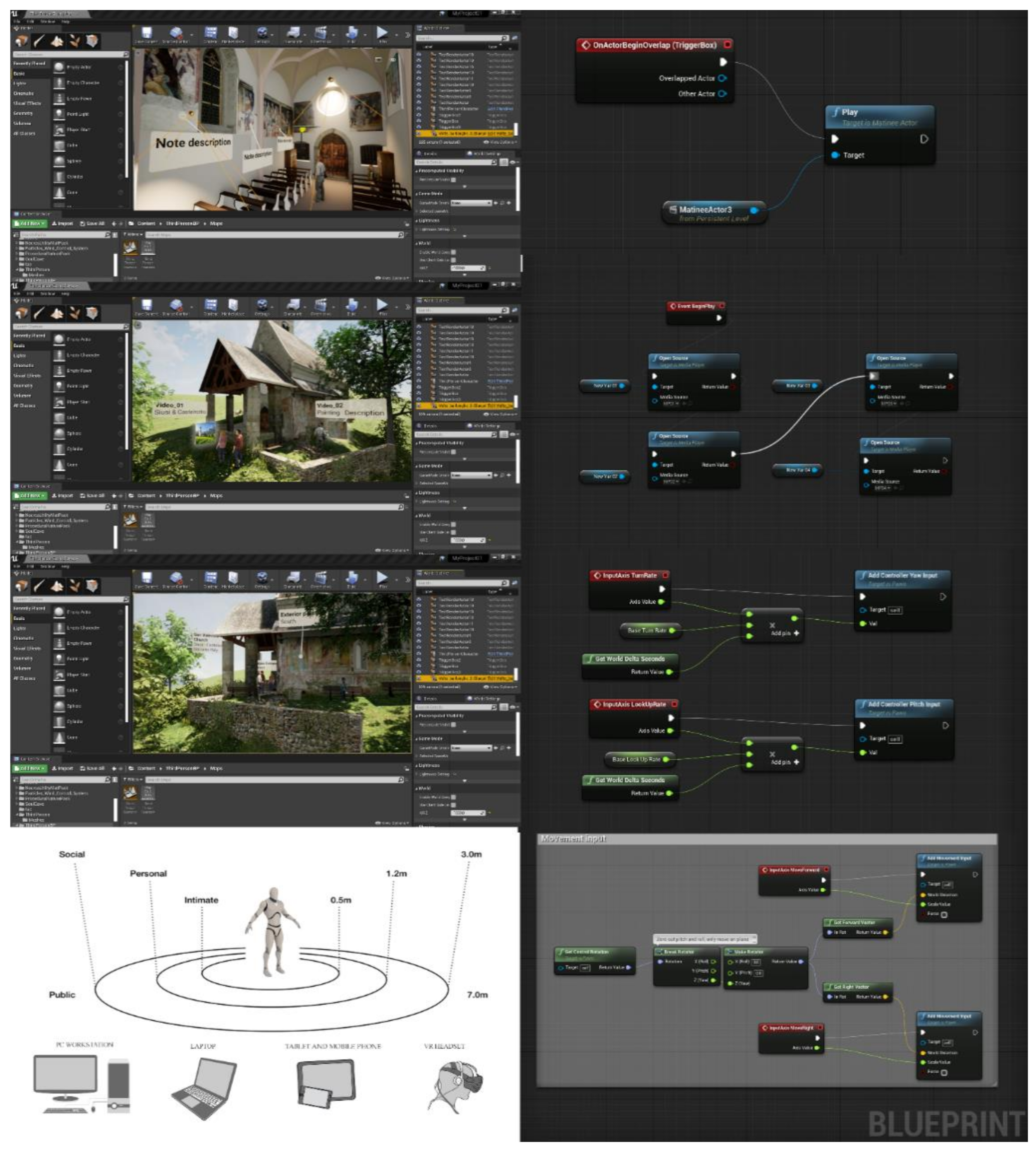
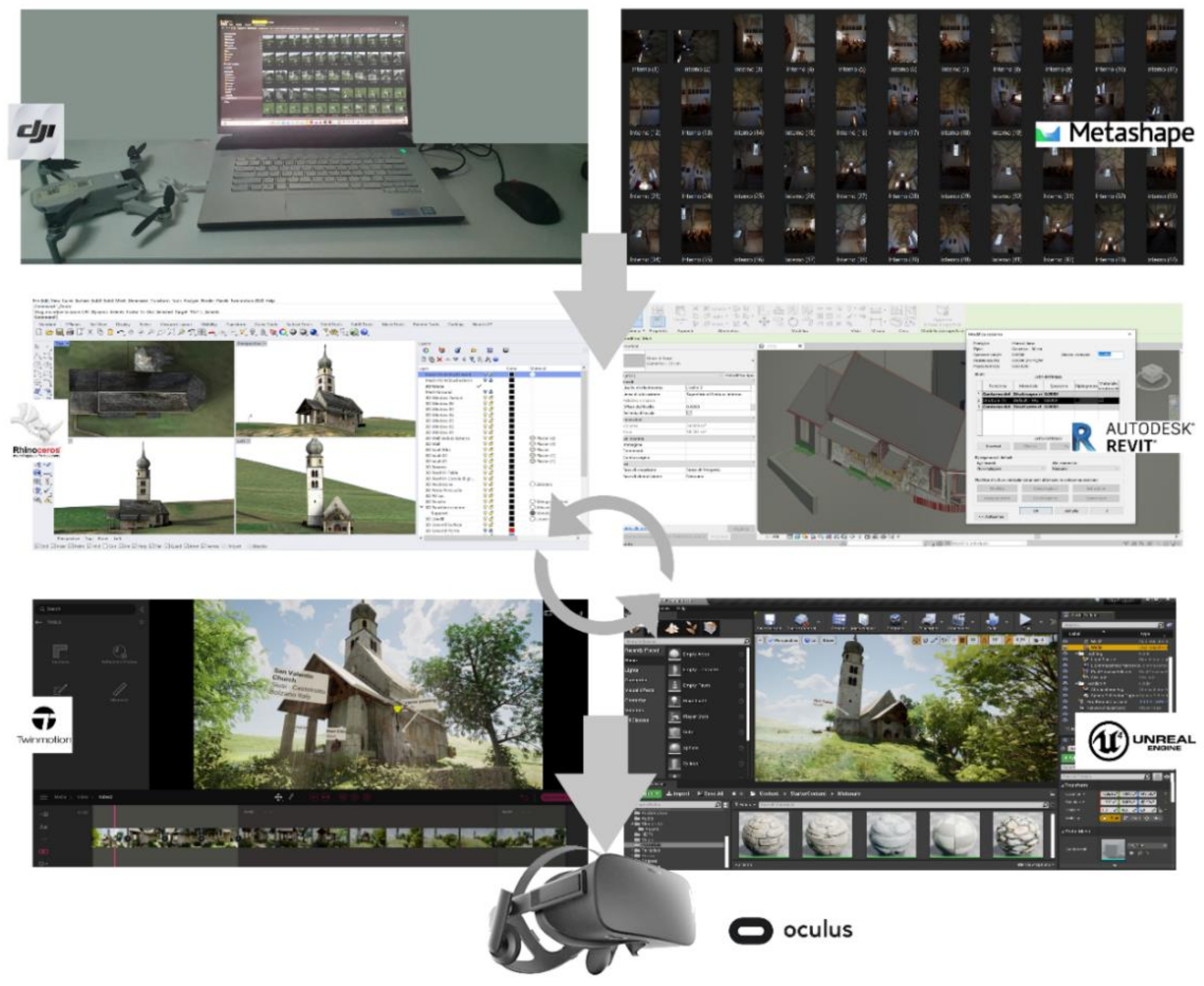
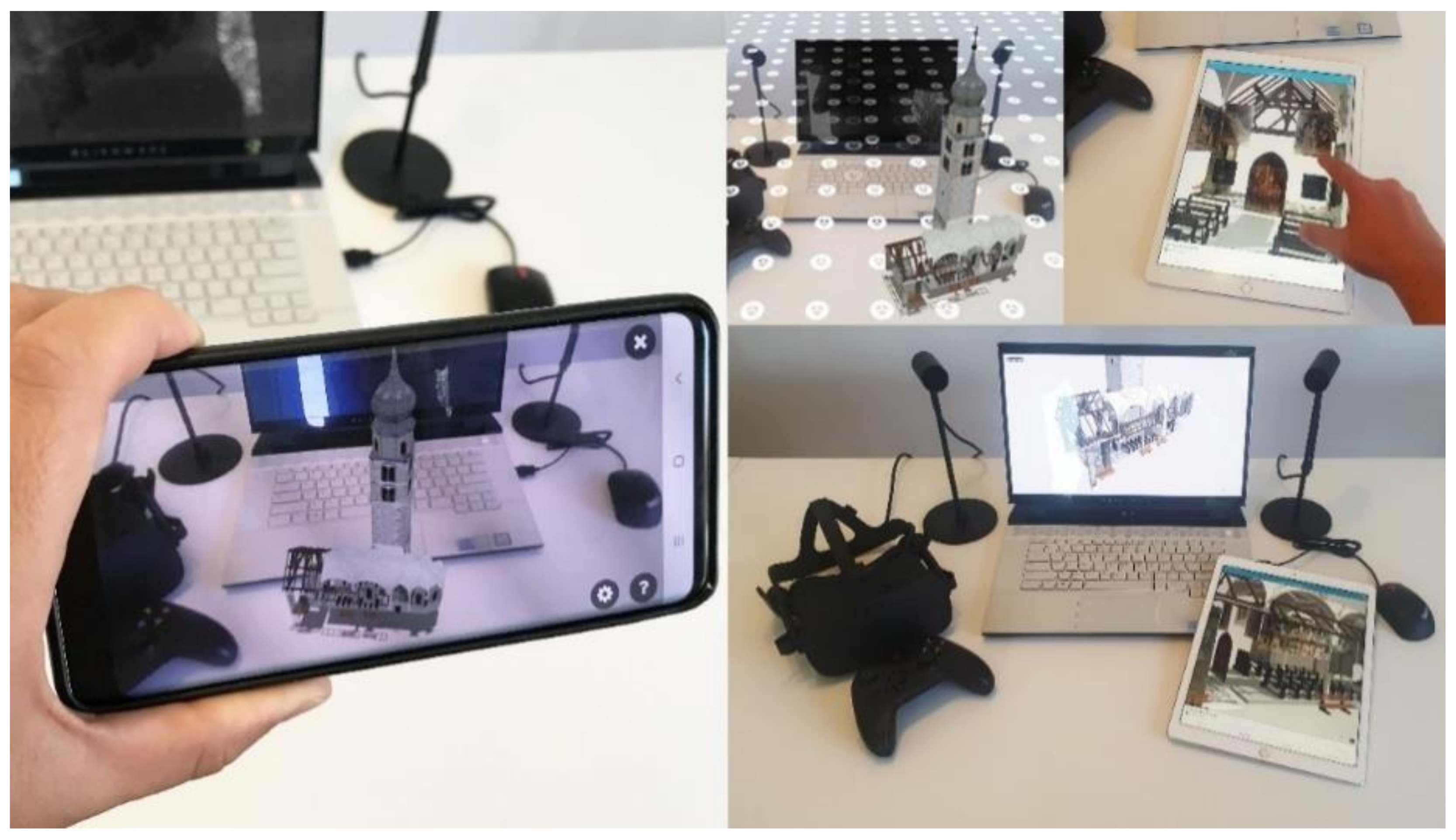
Publisher’s Note: MDPI stays neutral with regard to jurisdictional claims in published maps and institutional affiliations. |
© 2021 by the authors. Licensee MDPI, Basel, Switzerland. This article is an open access article distributed under the terms and conditions of the Creative Commons Attribution (CC BY) license (https://creativecommons.org/licenses/by/4.0/).