Article

Transfer Accuracy of Two 3D Printed Trays for Indirect Bracket Bonding—An In Vitro Pilot Study

1
Department of Orthodontics, University Medical Centre Regensburg, 93053 Regensburg, Germany
2
Department of Prosthetic Dentistry, University Medical Centre Regensburg, 93053 Regensburg, Germany
3
Department of Orthodontics, University Hospital Düsseldorf, 40225 Düsseldorf, Germany
4
Department of Oral Surgery, University Hospital Düsseldorf, 40225 Düsseldorf, Germany
*
Author to whom correspondence should be addressed.
Appl. Sci. 2021, 11(13), 6013; https://doi.org/10.3390/app11136013
Submission received: 11 June 2021 / Revised: 24 June 2021 / Accepted: 25 June 2021 / Published: 28 June 2021
(This article belongs to the Special Issue 3D Printed Materials Dentistry)

Abstract

:
The present study aimed to investigate the impact of hardness from 3D printed transfer trays and dental crowding on bracket bonding accuracy. Lower models (no crowding group: Little’s Irregularity Index (LII) < 3, crowding group: LII > 7, n = 10 per group) were selected at random, digitized, 3D printed, and utilized for semiautomated virtual positioning of brackets and tubes. Hard and soft transfer trays were fabricated with polyjet printing and digital light processing, respectively. Brackets and tubes were transferred to the 3D printed models and altogether digitized using intraoral scanning (IOS) and microcomputed tomography (micro-CT) for assessment of linear and angular deviations. Mean intra- and interrater reliability amounted to 0.67 ± 0.34/0.79 ± 0.16 for IOS, and 0.92 ± 0.05/0.92 ± 0.5 for the micro-CT measurements. Minor linear discrepancies were observed (median: 0.11 mm, Q1–Q3: −0.06–0.28 mm). Deviations in torque (median: 2.49°, Q1–Q3: 1.27–4.03°) were greater than angular ones (median: 1.81°, Q1–Q3: 1.05°–2.90°), higher for hard (median: 2.49°, Q1–Q3: 1.32–3.91°) compared to soft (median: 1.77°, Q1–Q3: 0.94–3.01°) trays (p < 0.001), and torque errors were more pronounced at crowded front teeth (p < 0.05). In conclusion, the clinician should carefully consider the potential impact of hardness and crowding on bracket transfer accuracy, specifically in torque and angular orientation.

1. Introduction

For orthodontic treatment of malocclusions, the insertion of fixed multibracket appliances is a common and reliable treatment option. Since the introduction of the straight-wire technique, ideal positioning of bracket has become of eminent importance [1,2,3,4,5]. Incorrectly positioned brackets can lead to undesirable tooth movement and extended treatment time.
Instead of chairside positioning (direct bonding), ideal bracket positions can be planned prior to treatment (indirect bonding). This approach was first described by Silverman and Cohen in 1972 [6] and has the advantage of unrestricted vision, reduced chair time, and increased patient comfort [7]. With regard to the rate of bracket loss in vivo and shear bond strength in vitro, direct and indirect approaches were reported to be comparable [8,9,10,11]. In the classical indirect bonding technique, brackets are positioned on plaster models and transfer templates are fabricated in the laboratory [12,13], which are frequently made of single- or double-layer silicones, vacuum-formed sheets of various thicknesses or a combination of both [14,15,16,17,18]. Nowadays, computer-assisted processes offer a time efficient alternative. Software tools allow for semiautomated determination of ideal bracket positions and virtual design of transfer trays [19], which are commonly manufactured by means of 3D printing.
Few in vitro studies compared transfer accuracy of CAD/CAM technology for indirect bracket placement to conventional ones and revealed comparable accuracies [20,21,22]. However, it is not yet clear whether severe crowding and the hardness of 3D-printed transfer trays impact on bracket transfer accuracy. Additionally, the workflow to assess potential bracket transfer inaccuracies remains to be validated, as artefacts from intraoral scanning may impair the measurements [23].
Therefore, the present study aimed at investigating the impact of transfer tray hardness and crowding on bracket transfer accuracy, and to validate whether intraoral scanning is an eligible tool to assess potential errors.

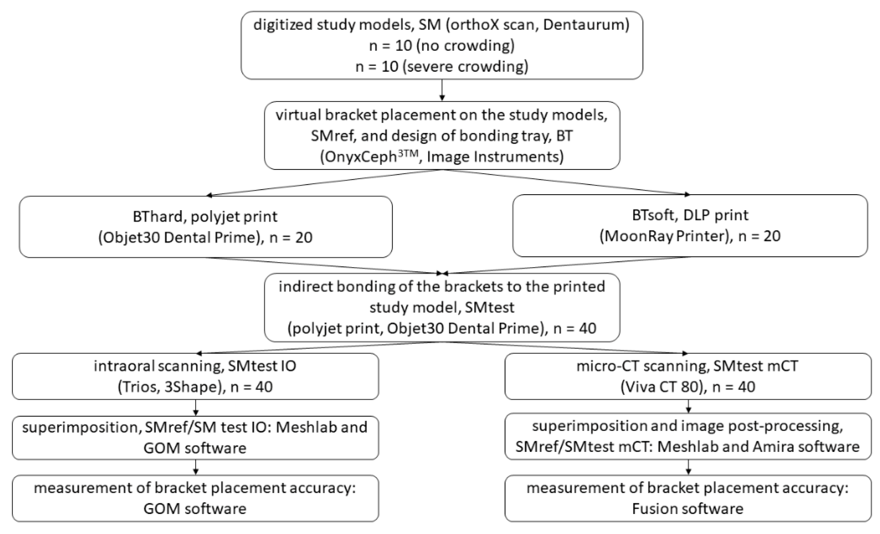
2. Materials and Methods

2.1. Selection of Casts

Twenty pre-treatment plaster models from the lower jaw were selected at random from the archive of the Department of Orthodontics, University Medical Centre Regensburg such that n = 10 models exhibited minor crowding (Little’s Irregularity Index (LII) < 3, “no crowding” group), and another n = 10 showed severe crowding (LII > 7, “crowding group”). The classification was performed with a digital caliper according to the LII, as described previously [24].
The following exclusion criteria were applied: no permanent dentition or second molars not completely erupted, agenesis, previous extractions, dental anomalies, displaced or retained canines, patients with syndromes. The study workflow is provided in detail in Figure 1.

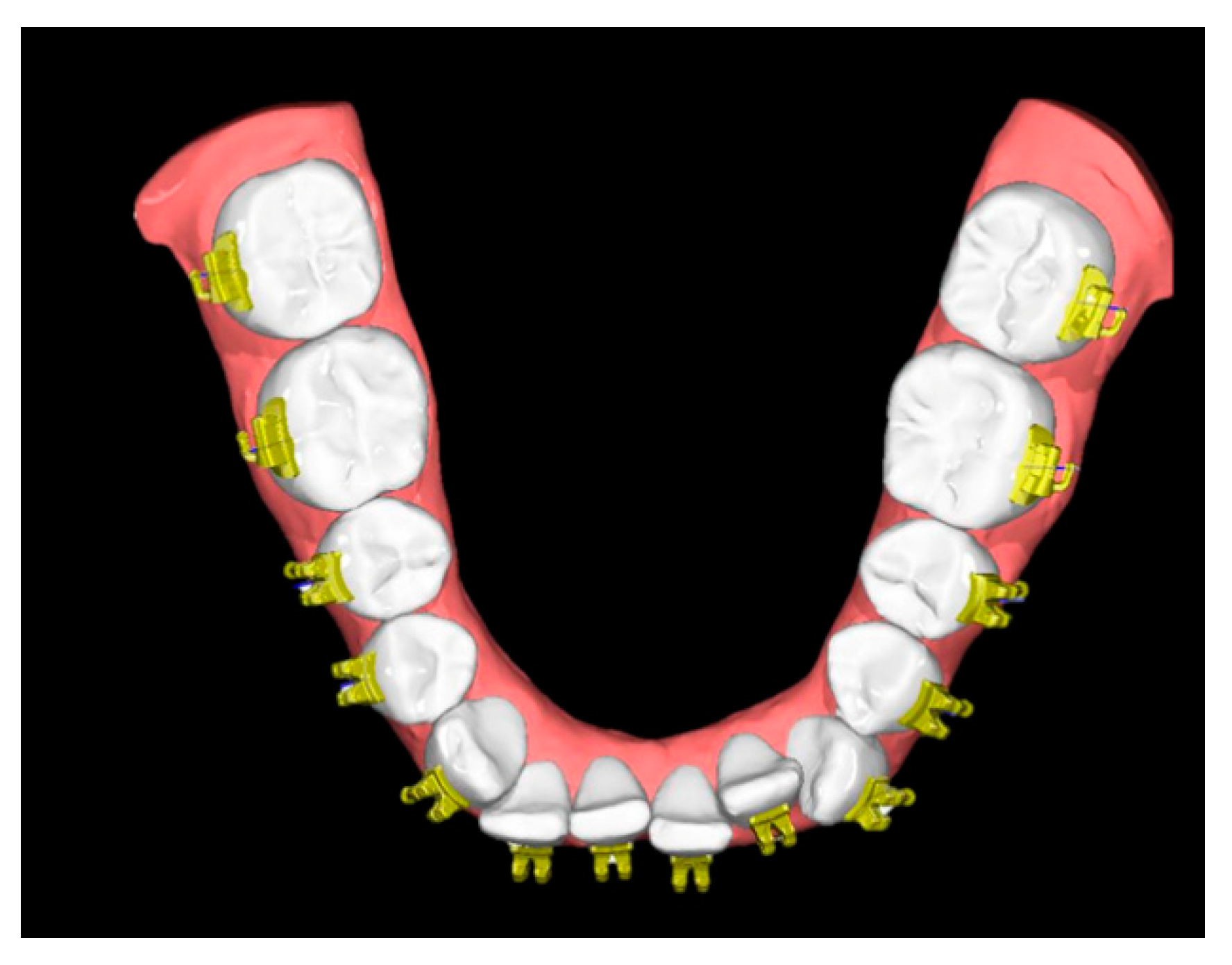
2.2. Model Preparation and Bracket Placement

The original plaster models were digitized using a 3D model scanner (orthoX®scan, Dentaurum, Ispringen, Germany). Each of the generated digital study models (SM) was printed twice using the Objet30 Dental Prime printer (Stratasys, Eden Prairie, MN, USA) using the high-speed mode (28 micron), VeroGlaze MED620 material and SUP705 support material (both Stratasys, Eden Prairie, MN, USA). The models were cleaned with a water jet and served as study models to which the brackets were bonded later (Figure 2A,B). Until usage they were stored in dry rice as reported previously and recommended by the manufacturer [25].
The SM were imported into a proprietary software (OnyxCeph3TM Lab software, Image Instruments, Chemnitz, Germany) for virtual placement of brackets/tubes utilizing the FA-Bonding module as follows: teeth 35–45 (Discovery smart bracket, Dentaurum, Ispringen, Germany), teeth 36, 37, 46, 47 (Ortho-Cast M series buccal tubes, Dentaurum, Ispringen, Germany).
The FA-Bonding module operates semiautomatically and utilizes the facial axis (FA) for automated bracket positioning along the vertical tooth axis. Minor adjustments were performed by one single experienced orthodontist (RJ). The SM together with the virtually placed brackets served as reference models (SMref) (Figure 3).

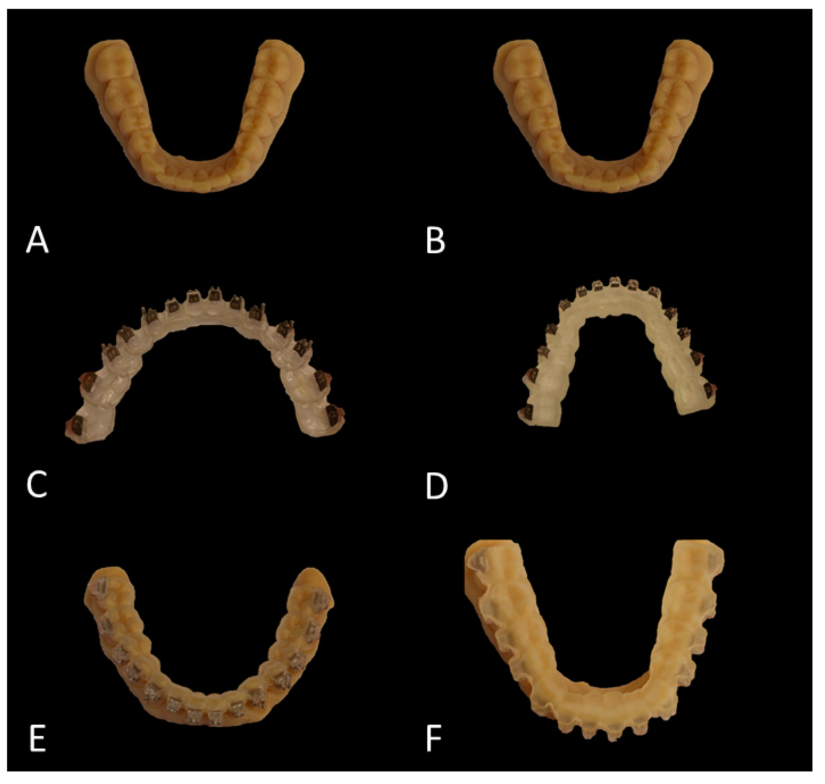
2.3. Planning and Printing of the Transfer Trays

The transfer trays were designed using the Bonding Tray 3D module (OnyxCeph3TM Lab software). A base covering the teeth and molds for the brackets and tubes was designed. In detail, the base had a thickness of 1 mm and covered all the occlusal/incisal surfaces as well as half of the lingual and about 1/3 of the labial surfaces of every tooth. The molds had a 0.6 mm thickness and covered the occlusal part of the brackets/tubes and overlapped the slot by 0.04 mm. Undercutting parts (up to 0.5 mm) were filled by the software.
Each tray was printed twice, one time with a hard and another with a soft printing material (Figure 2C,D): the hard transfer trays were printed horizontally in a polyjet printing process (Objet30 Dental Prime, Stratasys, Eden Prairie, MN, USA) using the high-speed mode (28 micron resolution) and biocompatible MED610 (shore D hardness 83–86; Stratasys, Eden Prairie, MN, USA) with support material SUP705 (Stratasys, Eden Prairie, MN, USA). After printing, the support material was removed by water jet cleaning and a hard toothbrush. The soft transfer trays were printed horizontally by means of a digital light processing (DLP) using the MoonRay Printer (SprintRay, LA, USA) with a 100 micron resolution and the biocompatible NextDent Ortho IBT (shore A 85 hardness; NextDent B.V., Soesterberg, The Netherlands).
After printing, the trays were washed for 20 min with Isopropanol (FormWash, Formlabs, Berlin, Germany) and light cured for 60 min at 45 °C (Curebox, Wicked Engineering, East Windsor, NJ, USA). For those trays that were printed with the DLP technology, an occlusal overlay plane was designed to avoid the need of adding support structures and increase the adhesion to the platform as it became possible to locate them horizontally.

2.4. Bracket Transfer and Bonding

For both types of transfer trays (hard and soft), the brackets and tubes were carefully positioned inside the respective molds (Figure 2C,D). A thin layer of dental wax was placed between the tubes and the tray to enable stable fixation. Then, the facial bases of the brackets and tubes were cleaned with acetone, and a thin layer of TransbondXT adhesive (3M, Monrovia, CA, USA) was applied to the bracket’s base and homogenously dispersed with a microbrush and a thin layer of TransbondXT primer (3M, Monrovia, CA, USA).
The templates were placed on the study models (Figure 2E,F) and gently fixated manually during curing with the Ortholux Luminous Curing Light (1600 mW/cm2, 3M, Monrovia, CA, USA). Curing was performed at each bracket and tube for 6 s at the mesial and distal site, respectively. Afterwards, the transfer trays were carefully removed, and excessive resin was eliminated using a frontal sickle scaler (HuFriedy, Frankfurt am Main, Germany) and adhesive removers at 10.000 rpm (Komet Dental, Lemgo, Germany). Until digitization, all study models with the bonded brackets and tubes (SMtest) were stored in boxes filled with dry rice [25].

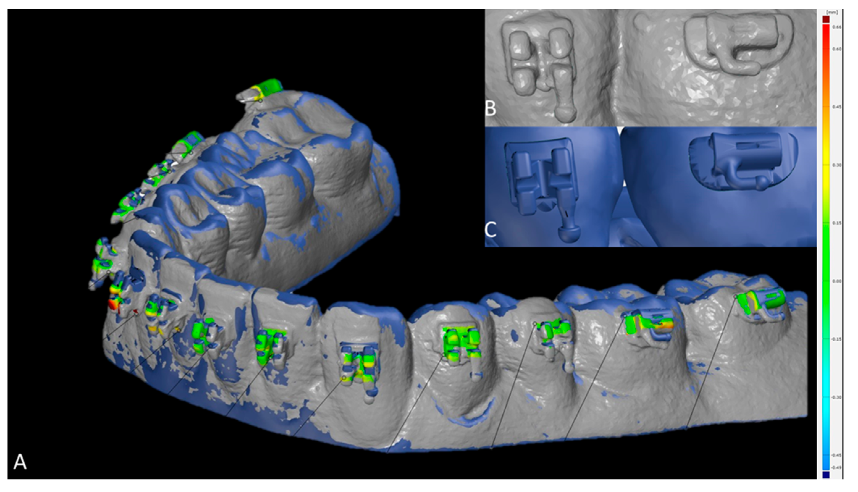
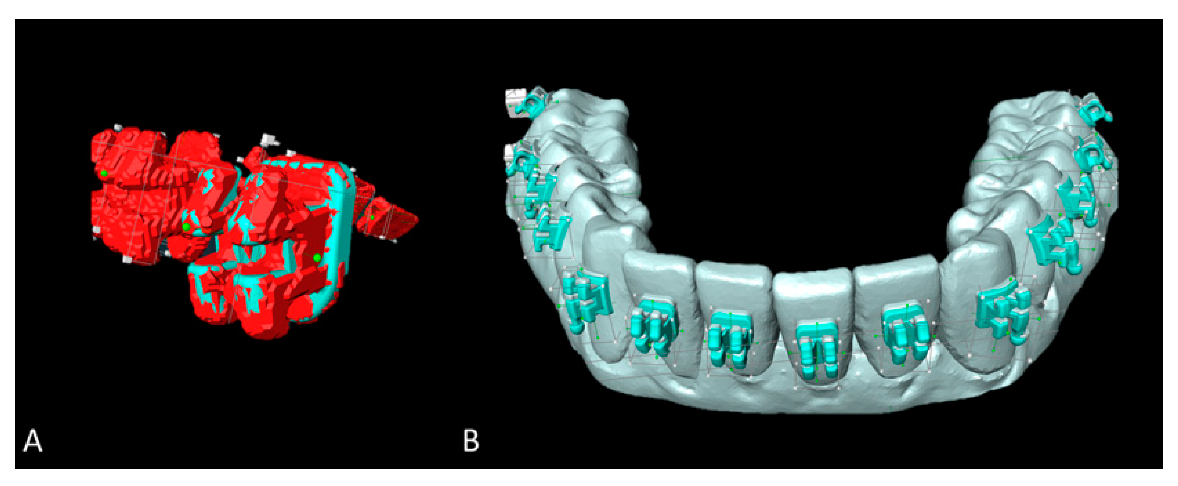
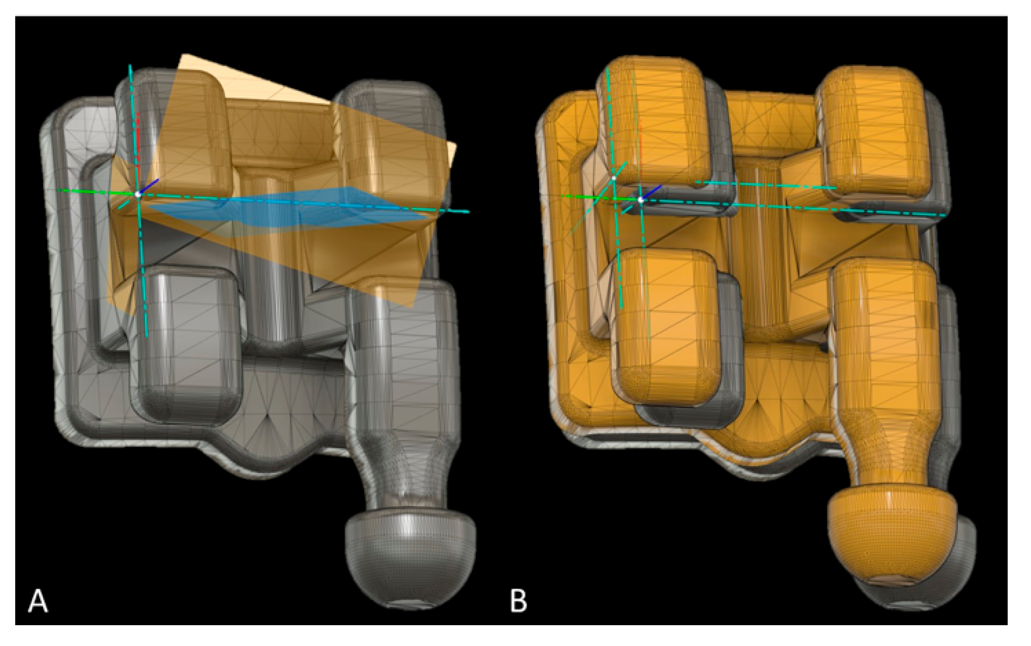
2.5. Digitization, Image Processing and Measurement of Bracket Placement Accuracy

2.5.1. Intraoral Scanning

SMtest models were covered with a thin layer of scanning spray (BlueSpray, Dreve Dentamid, Unna, Germany). The as-prepared models were digitized using an intraoral scanner (Trios 3, 3Shape, Kopenhagen, Denmark; setting: typical clinical setting, full arch scanning mode). Image registration of the SMtest-IO with SMref was achieved in two steps: first, a reference-point based pre-alignment was performed in MeshLab (MeshLab v1.3.3, Visual Computing Lab, ISTI, CNR). Fine registration was realized using the local best fit algorithm implemented in GOM Inspect 2018 software (GOM, Braunschweig, Germany). The fine-registration procedure was repeated until convergence as described earlier [26].
To assess the 3D accuracy of bracket placement, surface comparison was utilized. In case intraorally scanned brackets showed scanning errors (Figure 4B,C), the most likely correct areas were identified by a trained observer, which led to exclusion of the hooks at all brackets and tubes (Figure 4A). The minimum, maximum, mean and standard deviation values between SMtest-IO and SMref were recorded for each bracket and tube.

2.5.2. Micro-CT Scanning (Method Validation)

Digitization of SMtest was also achieved using a micro-CT (Viva CT 80, Scanco Medical, Brüttisellen, Switzerland). The scans were performed at 70 kVp, 114 μA, 535 ms integration time and 2× frame averaging, and reconstructed to a nominal isotropic voxel size of 39 µm. The so achieved SMtest-mCT models were segmented and surfaces were extracted using Amira software (v2019, Thermo Fisher Scientific, Berlin, Germany).
SMtest-mCT surfaces were aligned with the respective SMref models using a landmark-based registration procedure followed by an iterative closest point algorithm (Meshlab software) as described earlier [26]. Owing to metal artefacts on the micro-CT scans, each scanned bracket on the SMtest was replaced with the respective original bracket surface by superimposing the latter on the micro-scanned ones (Amira software). This technique enabled preservation of the true positions of the brackets on the digitized SMtest models (Figure 5A,B).
Bracket placement accuracy on SMtest-mCT models was assessed using Fusion 360 (Autodesk, San Rafael, CA, USA). All brackets and tubes were virtually separated from SMref and oriented along the global Cartesian coordinate system, and an additional local coordinate system was defined for every bracket/tube (Figure 6A). The disagreement between brackets from SMtest-mCT and SMref along the x-, y- and z-axes was recorded as mesial/distal, occlusal/gingival, buccal/oral deviation. The angular deviation between the vertical bracket axes was recorded as torque, and between the horizontal axes as angulation discrepancy (Figure 6B).

2.6. Sample Size Calculation

According to Pottier et al. [21] 91 observations per group would be necessary to detect a moderate effect size at a significance level of 0.05 with a 90% power. Therefore, 10 study models were included in each group.

2.7. Reliability of Measurements

To calculate intra- and interrater reliability, 20 casts were selected at random and all measurements, including the matching process, were performed again by the same investigator after a time interval of 4 weeks, and also by a second experienced investigator. To calculate the systematic error, the intraclass correlation coefficient (ICC; two-way mixed, absolute agreement) was calculated.

2.8. Statistical Analysis

The software IBM SPSS Statistics 25 (IBM, Armonk, NY, USA) and R [27] were used to analyze the data. For descriptive purposes, boxplots were created. According to Kolmogorov–Smirnov tests and visual inspection of boxplots, not all the data showed normal distribution. Thus, non-parametric Mann–Whitney U-test was used to compare brackets/tubes placed at casts with/without crowding, as well as for brackets/tubes bonded with hard/soft trays for linear and angular measurements at the molars, premolars, canines and incisors, respectively. The effect size r was calculated and interpreted in accordance with Cohen likewise to Pearson r, i.e., <0.3: low effect size; 0.3–0.5: medium effect size; >0.5: good effect size) [28].

3. Results

3.1. Reliability of Measurements

When SMtest-mCT models were utilized, the workflow reliability ranged from high to excellent. In detail, mean intra- and interrater reliability amounted to 0.917 ± 0.053 and 0.921 ± 0.045, respectively (Table S1 in Supplementary Materials). Visual inspection confirmed that artefact-impaired brackets from micro-CT scanning could be substituted with artefact-free surfaces from the original brackets by means of surface alignment, thus enabling accurate measurements of the metric and angular deviations.
When SMtest-IO models were utilized, mean intra- and interrater reliability amounted to 0.674 ± 0.341 and 0.785 ± 0.161, respectively, and ranged from −0.073 to 0.979 for intrarater, and from 0.388 to 0.975 for interrater values. A total of 12.5% (intrarater) and 31.3% (interrater) of the measurements indicated moderate reliability (ICC 0.50–0.75) and 25% (intrarater) as well as 6.3% (interrater) of the values demonstrated poor reliability (ICC < 0.5), respectively (Table S1 in Supplementary Materials). The low reliabilities owed to the fact that bracket surfaces digitized with the intraoral scanner presented several artefacts, which impaired identification of reliable areas to assess bracket transfer accuracy. Therefore, the SMtest-IO models were excluded at this point from the study, and only bracket transfer deviations assessed with the SMtest-mCT were reported.

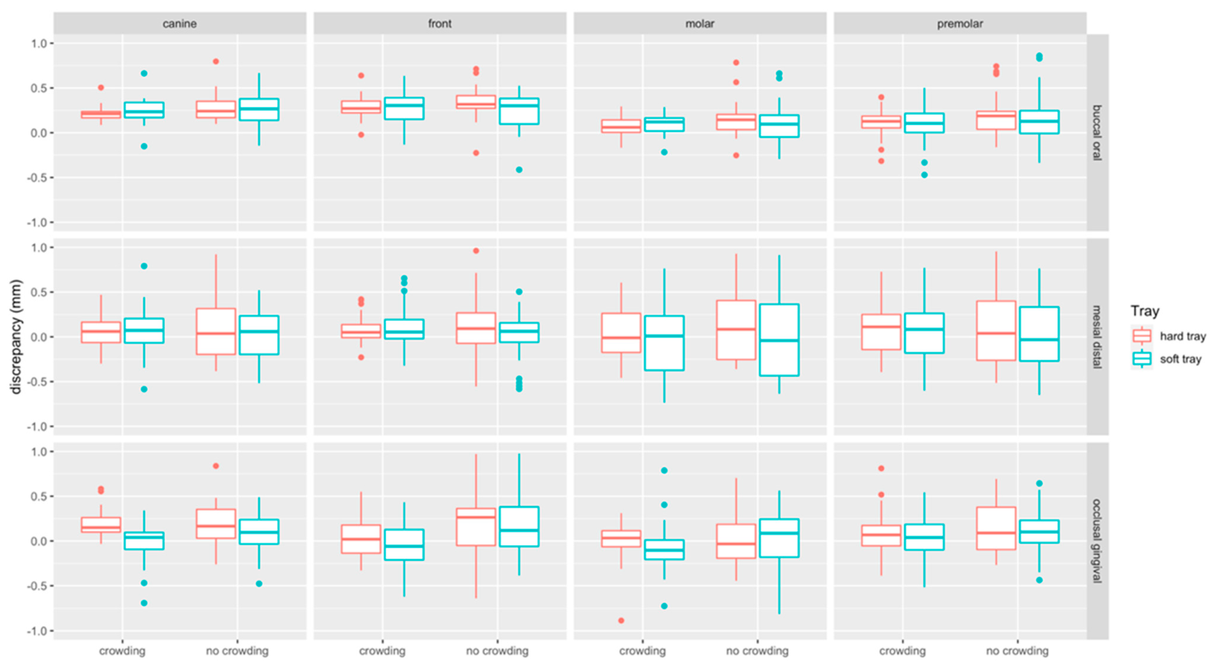
3.2. Bracket Bonding Accuracy (Linear Measurements)

Boxplots of linear measurements are provided in Figure 7. Discrepancies were most pronounced in the buccal/oral (median: 0.18 mm, Q1–Q3: 0.06–0.30 mm) compared to the mesial/distal (median: 0.054 mm, Q1–Q3: −0.18–0.26 mm) and occlusal/gingival direction (median: 0.06 mm, Q1– Q3: −0.11–0.23 mm). Linear discrepancies were more present at incisors (median: 0.15 mm, Q1–Q3: −0.02–0.31 mm) and canines (median: 0.16 mm, Q1–Q3: 0.01–0.23 mm) compared to molars (median: 0.05 mm, Q1–Q3: −0.01–0.21 mm) and premolars (median: 0.10 mm, Q1–Q3: −0.07–0.25 mm).

3.2.1. Impact of Crowding

Linear discrepancies were higher in the no crowding (median: 0.14 mm, Q1–Q3: −0.06–0.30 mm) compared to the crowding (median: 0.10 mm, Q1–Q3: −0.06–0.23 mm) group (p < 0.001). When splitting the data to assess the impact of crowding for the two types of trays and the respective tooth types, significant differences were found in occlusal/gingival direction, i.e., for hard and soft trays at front teeth (p = 0.015, p = 0.001, respectively), and for soft trays in the molar region (p = 0.007). For hard trays, a significant difference was noted in buccal-oral direction at molars (p = 0.029) (Table 1).

3.2.2. Impact of Tray Type

Linear discrepancies were higher for hard (median: 0.13 mm, Q1–Q3: −0.05–0.27 mm) compared to the soft (median: −0.08 mm, Q1–Q3: −0.08–0.26 mm) trays (p = 0.004). When splitting the data, significant differences were only detected in occlusal/gingival direction within the crowding group, i.e., at canines (p = 0.005), where the soft tray performed more accurately, and at molars (p = 0.002), where the soft trays transferred the tubes more gingivally (Table 1).

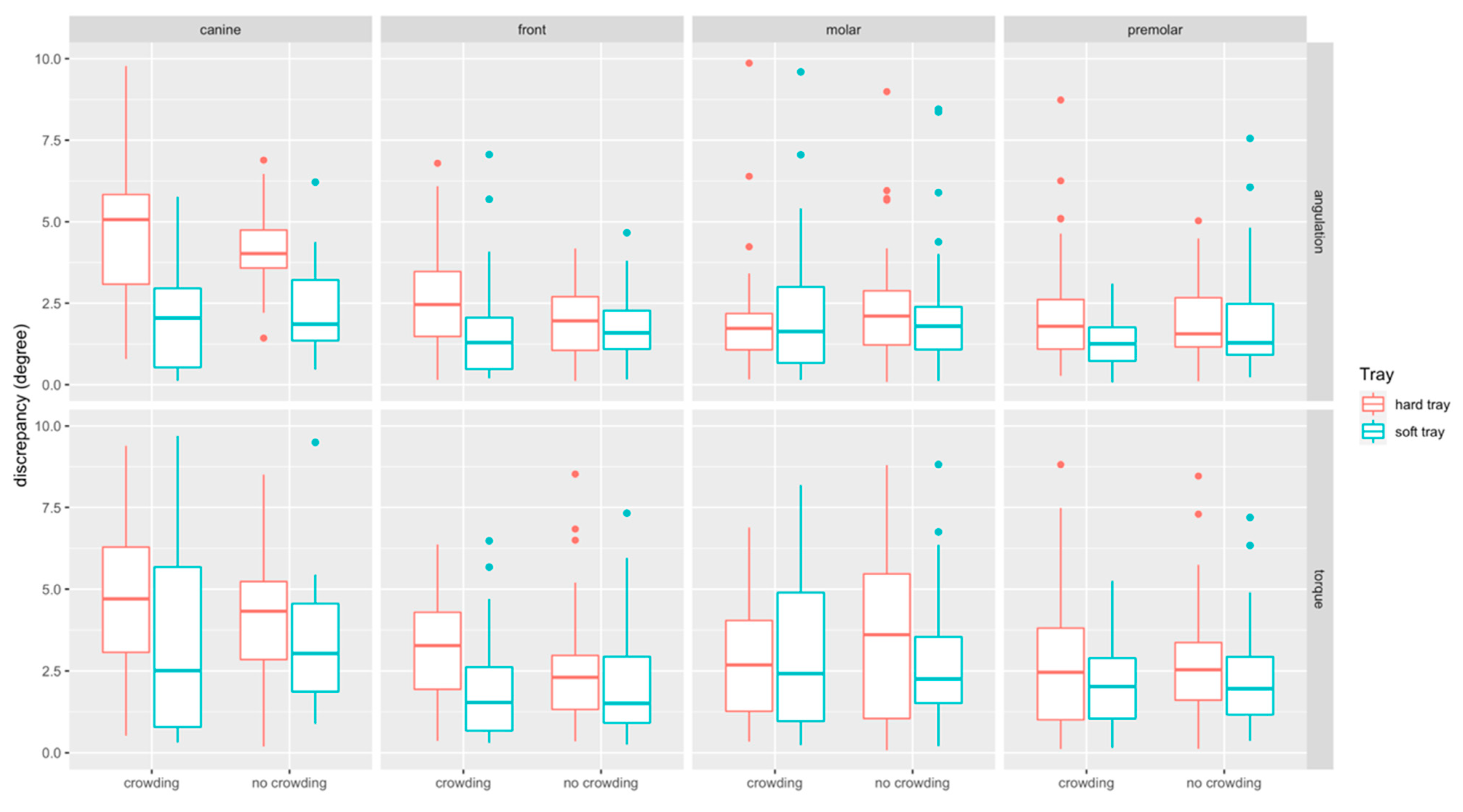
3.3. Bracket Bonding Accuracy (Angular Measurements)

The boxplots of angular measurements are provided in Figure 8. Discrepancies in torque (median: 2.49°, Q1–Q3: 1.27–4.03°) were higher than in angulation (median: 1.81°, Q1–Q3: 1.05–2.90°). Discrepancies were most pronounced at canines (median: 3.50°, Q1–Q3: −1.81–5.15°) and comparable at front teeth (median: 1.96°, Q1–Q3: 1.01–3.02 mm), molars (median: 2.09°, Q1–Q3: 1.09–3.79°) and premolars (median: 1.82°, Q1–Q3: 1.05–2.90°).

3.3.1. Impact of Crowding

Angular discrepancies were by trend higher in the crowding (median: 2.16°, Q1–Q3: 1.21–3.67°) compared to the no-crowding (median: 2.08°, Q1–Q3: 1.01–2.7°) group (p = 0.358). When splitting the data to assess the impact of crowding for the two types of trays and the respective tooth types, significant differences were found for torque at hard trays in the front region (p = 0.028) (Table 1).

3.3.2. Impact of the Tray Type

Angular discrepancies were higher for hard (median: 2.49°, Q1–Q3: 1.32–3.91°) compared to the soft (median: 1.77°, Q1–Q3: 0.94–3.01°) trays (p < 0.001). When splitting the data, significant differences were found in the crowding group, i.e., for angulation at front teeth (p = 0.001), canines (p < 0.001) and premolars (p = 0.009), and for torque at front teeth (p < 0.001), and in the no crowding group for angulation at canines (p < 0.001). For all these differences the transfer with the soft tray was more accurate (Table 1).

4. Discussion

The aim of the present in vitro study was to assess whether the hardness (shore A 85 vs. shore D83 –86) of 3D printed transfer trays and severe crowding impact on bracket bonding accuracy. Additionally, it was aimed to validate the workflow.
In the literature, different procedures for digitizing study models, e.g., intraoral scanners, 3D-model scanners or cone beam computed tomography (CBCT), were described for assessing the accuracy of transfer trays in digital workflows [29,30,31,32]. Matching intraoral scans (IOS) with the virtually planned reference models seems to be used most frequently and has the advantage that this workflow can be easily applied to clinical as well as in vitro settings, whereas microcomputed tomography (micro-CT) is limited to in vitro studies only. Nevertheless, full arch scanning in the presence of brackets might have an impact on scanning accuracy [33,34] and could therefore affect outcomes achieved with this technology. Previous studies did not evaluate the accuracy of workflows for assessing the accuracy of transfer trays or did not indicate whether the whole process including image registration was repeated to assess reliability. In our study, ICC values for intraorally scanned models indicated a very low reliability likely owing to significant artifacts at the scanned metal brackets and tubes. To some extent scanning accuracy may be impeded by the thin layer of scanning powder applied to the brackets, as scanning powder is suspected to increase scanning errors [35]. Nonetheless, distortion of the bracket area in intraoral scans was reported recently [36]. In the present analysis, the references and scanned surfaces showed a visible incongruence. Although only the apparently matching regions from the brackets were utilized for comparison in GOM software as described in [29], the intra- and interrater reliability ranged from excellent to poor in our experiment. Therefore, and despite having been used in the majority of previous experiments, the IOS approach was not found eligible to assess the accuracy of transfer trays in the present investigation. Instead, micro-CT scanning proved to be a highly reliable approach. Therefore, only the deviation measurements performed with this approach were reported.
The micro-CT workflow revealed minor linear discrepancies between planned and achieved bracket positions ranging from −0.06 to 0.28 mm (1st–3rd quartile). Interestingly, linear deviations were slightly but significantly lower in severe crowding situations, whereas no overall impact of crowding was identified. In the subgroup analysis, significant differences were most frequently observed at front teeth, where brackets were bonded more accurately in occlusal/gingival direction when severe crowding was present. In contrast, in crowding groups, tubes were located significantly more gingival when soft trays were utilized.
Angular deviations were by trend higher when crowding was present, and torque discrepancies reached significance at front teeth. Bracket transfer with hard trays resulted in greater angular deviations compared to soft trays. The greatest impact of bracket hardness was noted on canines, where soft trays improved median angular discrepancies by 2.16° and 3.03° in no crowding and crowding situations, respectively.
Regarding the amount of deviations, linear discrepancies ≤ 0.5 mm and angular deviations of ≤2° were considered to be acceptable as suggested by The American Board of Orthodontists (ABO) [37] and further studies [21,32], despite some authors recommending more strict ranges [30,38].
In the present analysis, linear discrepancies were within the ABO range of 0.5 mm, which is also in line with previous findings [20,21,29]. Deviations in torque were greater than in angulation. Especially when brackets were bonded with hard trays, values were frequently greater than 2° and also clearly higher as reported previously [20,21,29]. Besides the digitization method and measurement workflow, reasons for the greater angular deviations may also owe to the design of the trays, handling, crowding, and material properties, as discussed below.
Few studies investigated the transfer accuracy of 3D printed transfer trays. Zhang et al. compared different variants (3D printed trays for each single tooth versus 3D printed trays for the whole dental arch) with two types of double-layer vacuum formed trays and found no significant differences [22]). However, this study performed caliper measurements in a single direction only. Niu et al. found that 3D printed trays provided better transfer accuracy compared to vacuum-formed ones, and in line with the present investigation, linear control was superior to angular control, whereas angular values also exceeded the ABO-ranges [20]. In contrast, satisfactory angular control was reported for an L-type design of 3D printed trays that was employed in an in vivo study by Xue et al. {29]. This approach is of particular interest, as it provided a positioning template. This allowed a combination of direct bonding and a-priori planning of bracket positions. When comparing 3D printed with conventional silicone trays, Pottier et al. reported that conventional silicone enabled a more accurate bracket transfer [24], and accurate bracket transfer using silicone trays was also reported by other authors [18,38]. The high precision of this conventional laboratory workflow may owe to the material properties of silicone. Additionally, brackets are fully covered by the tray which may prevent bracket movement during transfer.
In contrast, due to material properties of the 3D printed transfer trays, no full coverage of brackets was possible, and the trays overlapped the slots by 0.04 mm only. This design resulted in a difficult handling specifically at front teeth and canines in the presence of crowding because brackets were located remarkably close to each other. Additionally, placement in hard trays was particularly challenging as brackets had to be pressed with the fingertips into the tight molds. Whereas bracket placement was easier in the soft tray group, brackets did not remain stable in their position when minor deformations of the soft tray occurred. This might explain the more gingival placement of molar tubes in the presence of severe crowding.
To the best knowledge of the authors, no previous study investigated the impact of crowding and hardness of the bonding tray on bracket transfer accuracy. Against our a-priori assumptions, linear bracket transfer accuracy was slightly but significantly higher in the crowding group. Interestingly, crowded front teeth seemed to improve the vertical fit of the trays, thus prohibiting a gingival bracket displacement. However, when hard transfers were utilized the tight fit of the transfer tray did not prevent deviations in torque, which were most pronounced at front teeth and canines in the present of crowding. The authors suspect that this might be explained by increased tension due to severely crowded incisors resulting in deformation of the lower part of the hard tray. In the presence of crowding bonding with the hard tray further resulted in increased angular deviations at front teeth, canines and premolars.
One of limitations of the present study is that cases with mild crowding (LII 3–7) were not included since the present study aimed at assessing whether crowding has an overall impact. The fact that the present study reports in vitro findings, and that the micro-CT workflow cannot be established for clinical trials, needs to be considered as another limitation. Additionally, the present study did not evaluate different designs in terms of thickness, extension and bracket covering, and further materials. Eventually, the impact of the different resolutions of the two printing technologies could not be assessed.

5. Conclusions

  • The present study found that intraoral scanning may severely impede measurements to assess the accuracy of bracket transfer, whereas micro-CT was shown to be a highly reliable alternative for in vitro settings.
  • We demonstrated that linear discrepancies were below the ABO-range of 0.5 mm, most of the angular discrepancies were not within the clinical acceptable limit of 2°.
  • Severe crowding and transfer tray hardness have an impact on transfer tray accuracy, and bonding with the soft transfer tray was more accurate in cases of severe crowding.
  • Front teeth were most frequently affected by bonding errors, followed by canines and molars.

Supplementary Materials

The following are available online at https://www.mdpi.com/article/10.3390/app11136013/s1. Table S1: Intra- and interrater reliability of the different workflows.

Author Contributions

R.J.: Conceptualization, methodology, investigation, formal analysis, writing—original draft. J.B.: investigation, writing—review and editing. A.S.: methodology, investigation, writing—review and editing. M.H.: investigation, writing—review and editing. R.K.: investigation, writing—review and editing. N.R.: investigation, writing—review and editing. P.P.: resources, supervision, writing—review and editing. D.D.: resources, supervision, writing—review and editing. K.B.: conceptualization, investigation, formal analysis, writing—original draft. All authors have read and agreed to the published version of the manuscript.

Funding

This research received no external funding.

Institutional Review Board Statement

Not applicable.

Informed Consent Statement

Not applicable.

Data Availability Statement

Data will be provided upon reasonable request.

Acknowledgments

The authors thank Dentaurum and C3D.digital for donating the brackets/tubes and the DLP printed transfer trays utilized in the present investigation.

Conflicts of Interest

All authors declare no conflict of interest.

References

  1. Andrews, L.F. The six keys to normal occlusion. Am. J. Orthod. 1972, 62, 296–309. [Google Scholar] [CrossRef]
  2. Andrews, L.F. The straight-wire appliance, origin, controversy, commentary. J. Clin. Orthod. 1976, 10, 99–114. [Google Scholar]
  3. Andrews, L.F. The straight-wire appliance. Explained and compared. J. Clin. Orthod. 1976, 10, 174–195. [Google Scholar] [PubMed]
  4. Andrews, L.F. Straight Wire: The Concept and Appliance; Wells: San Diego, CA, USA, 1989; ISBN 0961625600. [Google Scholar]
  5. Shpack, N.; Geron, S.; Floris, I.; Davidovitch, M.; Brosh, T.; Vardimon, A.D. Bracket placement in lingual vs labial systems and direct vs indirect bonding. Angle Orthod. 2007, 77, 509–517. [Google Scholar] [CrossRef] [Green Version]
  6. Silverman, E.; Cohen, M.; Gianelly, A.A.; Dietz, V.S. A universal direct bonding system for both metal and plastic brackets. Am. J. Orthod. 1972, 62, 236–244. [Google Scholar] [CrossRef]
  7. Sondhi, A. Efficient and effective indirect bonding. Am. J. Orthod. Dentofac. Orthop. 1999, 115, 352–359. [Google Scholar] [CrossRef]
  8. Yi, G.K.; Dunn, W.J.; Taloumis, L.J. Shear bond strength comparison between direct and indirect bonded orthodontic brackets. Am. J. Orthod. Dentofac. Orthop. 2003, 124, 577–581. [Google Scholar] [CrossRef]
  9. Linn, B.J.; Berzins, D.W.; Dhuru, V.B.; Bradley, T.G. A comparison of bond strength between direct- and indirect-bonding methods. Angle Orthod. 2006, 76, 289–294. [Google Scholar] [CrossRef]
  10. Menini, A.; Cozzani, M.; Sfondrini, M.F.; Scribante, A.; Cozzani, P.; Gandini, P. A 15-month evaluation of bond failures of orthodontic brackets bonded with direct versus indirect bonding technique: A clinical trial. Prog. Orthod. 2014, 15, 70. [Google Scholar] [CrossRef] [PubMed] [Green Version]
  11. Swetha, M.; Pai, V.S.; Sanjay, N.; Nandini, S. Indirect versus direct bonding—A shear bond strength comparison: An in vitro study. J. Contemp. Dent. Pract. 2011, 12, 232–238. [Google Scholar]
  12. McLaughlin, R.P.; Bennett, J.C.; Trevisi, H.J. Systemized Orthodontic Treatment Mechanics; Reprinted; Mosby: Edinburgh, UK, 2002; ISBN 0-7234-3171-X. [Google Scholar]
  13. Ciuffolo, F.; Tenisci, N.; Pollutri, L. Modified bonding technique for a standardized and effective indirect bonding procedure. Am. J. Orthod. Dentofac. Orthop. 2012, 141, 504–509. [Google Scholar] [CrossRef]
  14. Hickham, J.H. Predictable indirect bonding. J. Clin. Orthod. 1993, 27, 215–217. [Google Scholar]
  15. Gracco, A.; Tracey, S. The insignia system of customized orthodontics. J. Clin. Orthod. 2011, 45, 442–451. [Google Scholar] [PubMed]
  16. Kalange, J.T. Ideal appliance placement with APC brackets and indirect bonding. J. Clin. Orthod. 1999, 33, 516–526. [Google Scholar] [PubMed]
  17. Matsuno, I.; Okuda, S.; Nodera, Y. The hybrid core system for indirect bonding. J. Clin. Orthod. 2003, 37, 160–168. [Google Scholar]
  18. Castilla, A.E.; Crowe, J.J.; Moses, J.R.; Wang, M.; Ferracane, J.L.; Covell, D.A. Measurement and comparison of bracket transfer accuracy of five indirect bonding techniques. Angle Orthod. 2014, 84, 607–614. [Google Scholar] [CrossRef] [Green Version]
  19. Duarte, M.E.A.; Gribel, B.F.; Spitz, A.; Artese, F.; Miguel, J.A.M. Reproducibility of digital indirect bonding technique using three-dimensional (3D) models and 3D-printed transfer trays. Angle Orthod. 2020, 90, 92–99. [Google Scholar] [CrossRef] [Green Version]
  20. Niu, Y.; Zeng, Y.; Zhang, Z.; Xu, W.; Xiao, L. Comparison of the transfer accuracy of two digital indirect bonding trays for labial bracket bonding. Angle Orthod. 2020. [Google Scholar] [CrossRef]
  21. Pottier, T.; Brient, A.; Turpin, Y.L.; Chauvel, B.; Meuric, V.; Sorel, O.; Brezulier, D. Accuracy evaluation of bracket repositioning by indirect bonding: Hard acrylic CAD/CAM versus soft one-layer silicone trays, an in vitro study. Clin. Oral Investig. 2020, 24, 3889–3897. [Google Scholar] [CrossRef] [PubMed]
  22. Zhang, Y.; Yang, C.; Li, Y.; Xia, D.; Shi, T.; Li, C. Comparison of three-dimensional printing guides and double-layer guide plates in accurate bracket placement. BMC Oral Health 2020, 20, 127. [Google Scholar] [CrossRef]
  23. Koch, P.J. Measuring the accuracy of a computer-aided design and computer-aided manufacturing-based indirect bonding tray. Am. J. Orthod. Dentofac. Orthop. 2020, 158, 315. [Google Scholar] [CrossRef] [PubMed]
  24. Little, R.M. The Irregularity Index: A quantitative score of mandibular anterior alignment. Am. J. Orthod. 1975, 68, 554–563. [Google Scholar] [CrossRef]
  25. Koretsi, V.; Kirschbauer, C.; Proff, P.; Kirschneck, C. Reliability and intra-examiner agreement of orthodontic model analysis with a digital caliper on plaster and printed dental models. Clin. Oral Investig. 2019, 23, 3387–3396. [Google Scholar] [CrossRef] [PubMed]
  26. Becker, K.; Wilmes, B.; Grandjean, C.; Drescher, D. Impact of manual control point selection accuracy on automated surface matching of digital dental models. Clin. Oral Investig. 2018, 22, 801–810. [Google Scholar] [CrossRef]
  27. R Core Team. R: A Language and Environment for Statistical Computing; R Foundation for Statistical Computing: Vienna, Austria, 2018. [Google Scholar]
  28. Cohen, J. Statistical Power Analysis for the Behavioral Sciences, 2nd ed.; Taylor and Francis: Hoboken, NJ, USA, 2013; ISBN 9780805802832. [Google Scholar]
  29. Xue, C.; Xu, H.; Guo, Y.; Xu, L.; Dhami, Y.; Wang, H.; Liu, Z.; Ma, J.; Bai, D. Accurate bracket placement using a computer-aided design and computer-aided manufacturing-guided bonding device: An in vivo study. Am. J. Orthod. Dentofac. Orthop. 2020, 157, 269–277. [Google Scholar] [CrossRef] [Green Version]
  30. Süpple, J.; von Glasenapp, J.; Hofmann, E.; Jost-Brinkmann, P.-G.; Koch, P.J. Accurate bracket placement with an indirect bonding method using digitally designed transfer models printed in different orientations—An in vitro study. JCM 2021, 10, 2002. [Google Scholar] [CrossRef] [PubMed]
  31. Möhlhenrich, S.C.; Alexandridis, C.; Peters, F.; Kniha, K.; Modabber, A.; Danesh, G.; Fritz, U. Three-dimensional evaluation of bracket placement accuracy and excess bonding adhesive depending on indirect bonding technique and bracket geometry: An in-vitro study. Head Face Med. 2020, 16, 17. [Google Scholar] [CrossRef] [PubMed]
  32. Grünheid, T.; Lee, M.S.; Larson, B.E. Transfer accuracy of vinyl polysiloxane trays for indirect bonding. Angle Orthod. 2016, 86, 468–474. [Google Scholar] [CrossRef] [Green Version]
  33. Heo, H.; Kim, M. The effects of orthodontic brackets on the time and accuracy of digital impression taking. Int. J. Environ. Res. Public Health 2021, 18, 5282. [Google Scholar] [CrossRef]
  34. Kim, Y.-K.; Kim, S.-H.; Choi, T.-H.; Yen, E.H.; Zou, B.; Shin, Y.; Lee, N.-K. Accuracy of intraoral scan images in full arch with orthodontic brackets: A retrospective in vivo study. Clin. Oral Investig. 2021. [Google Scholar] [CrossRef]
  35. Quaas, S.; Loos, R.; Sporbeck, H.; Luthardt, R. Analyse des einflusses der puderapplikation auf die genauigkeit optischer digitalisierungen. Dtsch. Zahnarztl. Z. 2005, 60, 96–99. [Google Scholar]
  36. Kang, S.-J.; Kee, Y.-J.; Lee, K.C. Effect of the presence of orthodontic brackets on intraoral scans. Angle Orthod. 2021, 91, 98–104. [Google Scholar] [CrossRef]
  37. Casko, J.S.; Vaden, J.L.; Kokich, V.G.; Damone, J.; James, R.; Cangialosi, T.J.; Riolo, M.L.; Owens, S.E.; Bills, E.D. Objective grading system for dental casts and panoramic radiographs. Am. J. Orthod. Dentofac. Orthop. 1998, 114, 589–599. [Google Scholar] [CrossRef]
  38. Schmid, J.; Brenner, D.; Recheis, W.; Hofer-Picout, P.; Brenner, M.; Crismani, A.G. Transfer accuracy of two indirect bonding techniques-an in vitro study with 3D scanned models. Eur. J. Orthod. 2018, 40, 549–555. [Google Scholar] [CrossRef] [PubMed]
Figure 1. Flow diagram detailing the study workflow.
Applsci 11 06013 g001
Figure 2. Overview of the bracket placement workflow. (A,B) Printed study models (SM). (C,D) Hard (C) and soft (D) tray with brackets placed inside the respective molds. (E,F) Printed casts with the brackets indirectly bonded by means of the hard (E) and soft (F) transfer tray.
Applsci 11 06013 g002
Figure 3. Reference model consisting of a digitized study model and the semiautomatically positioned brackets/tubes (SMref).
Applsci 11 06013 g003
Figure 4. Measurement of the bracket transfer accuracy with GOM software. (A) Superimposed study models scanned with intraoral scanner (SMtest-IO) visualized in grey and reference study models (SMref) visualized in blue; distances are coded by heatmap coloring. (B) Scanned brackets from SMtest-IO in higher magnification. (C) Original brackets from SMref in higher magnification.
Applsci 11 06013 g004
Figure 5. Superimposition and image post-processing with Amira software. (A) Micro-CT scanned brackets (red) and the superimposed original brackets (green). (B) Reference study models (SMref) visualized in grey and corrected brackets from micro-CT scanned study models (SMtest-mCT) visualized in turquoise.
Applsci 11 06013 g005
Figure 6. Measurement of bracket transfer accuracy with Fusion software; (A) reference bracket with the local coordinate system defined through the three planes (yellow and blue). (B) Reference bracket and test bracket (yellow) to measure the linear and angular bracket bonding accuracy (mm, degree).
Applsci 11 06013 g006
Figure 7. Boxplots detailing the accuracy of bracket transfer for lingual measurements. Results are summarized for the canines, front teeth, molars, and premolars and split up into hard/soft trays and no crowding/crowding. A positive/negative value indicates mesial/distal, buccal/oral or occlusal/gingival displacement, respectively.
Applsci 11 06013 g007
Figure 8. Boxplots detailing the accuracy of bracket transfer for angular measurements. Results are summarized for the canines, front teeth, molars, and premolars and split up into hard/soft trays and no crowding/crowding.
Applsci 11 06013 g008
Table 1. Descriptive statistics for the subgroup analysis of the bracket transfer accuracies for linear and angular measurements. Results are summarized for the canines, front teeth, molars, and premolars and split up into hard/soft trays and no crowding/crowding. A positive/negative value indicates mesial/distal, buccal/oral or occlusal/gingival displacement. Medians (MD) and interquartile ranges (IQR), mm or degree are given. Comparison between crowding vs. no crowding groups and hard vs. soft trays was performed using the Mann–Whitney U-test. The p-values for comparison of hard vs. soft trays are presented in the lines, for crowding vs. no crowding in the right column. Pearson-correlation coefficient (r) was calculated in addition to measure the effect size, and was interpreted as follows: <0.3 low, 0.3–0.5 medium, >0.5 good effect size.
Tooth TypeTrayMeasurementMDIQRMDIQRp-Value
No crowding (LII < 3)Crowding (LII > 7)Crowding vs. no crowding
Canine (n = 40)HardAngulation (°)4.021.335.072.880.529
SoftAngulation (°)1.862.072.042.590.445
p-value hard vs. soft tray (r)<0.001 (0.58) ***<0.001 (0.56) ***
HardBuccal/oral (mm)0.240.20.210.090.201
SoftBuccal/oral (mm)0.270.290.230.180.698
p-value hard vs. soft tray (r)0.9680.327
HardMesial/distal (mm)0.040.540.060.240.989
SoftMesial/distal (mm)0.060.450.070.380.678
p-value hard vs. soft tray (r)0.4950.841
HardOcclusal/gingival (mm)0.160.370.150.240.799
SoftOcclusal/gingival (mm)0.100.290.040.210.211
p-value hard vs. soft tray (r)0.3980.005 (0.45) **
HardTorque (°)4.322.634.73.320.461
SoftTorque (°)3.523.042.515.040.341
p-value hard vs. soft tray. (r)0.2890.096
Front (n = 80)HardAngulation (°)1.961.72.462.250.053
SoftAngulation (°)1.591.191.291.640.178
p-value hard vs. soft tray (r)0.3080.001 (0.39) **
HardBuccal/oral (mm)0.320.150.270.140.083
SoftBuccal/oral (mm)0.300.300.30.240.722
p-value hard vs. soft tray (r)0.0650.923
HardMesial/distal (mm)0.090.380.050.150.607
SoftMesial/distal (mm)0.060.220.050.260.624
p-value hard vs. soft tray (r)0.3840.769
HardOcclusal/gingival (mm)0.260.430.020.320.015 (0.27) *
SoftOcclusal/gingival (mm)0.120.45−0.070.370.001 (0.36) *
p-value hard vs. soft tray (r)0.5540.068
HardTorque (°)2.312.013.282.490.028 (0.25) *
SoftTorque (°)1.642.341.542.070.439
p-value hard vs. soft tray (r)0.312<0.001 (0.41) ***
Molar
(n= 80)
HardAngulation (°)2.112.011.731.220.163
SoftAngulation (°)1.81.351.652.80.577
p-value hard vs. soft tray (r)0.3660.773
HardBuccal/oral (mm)0.140.170.060.150.029 (0.24) *
SoftBuccal/oral (mm)0.100.250.120.150.6
p-value hard vs. soft tray (r)0.140.296
HardMesial/distal (mm)0.080.68−0.010.450.788
SoftMesial/distal (mm)−0.040.820.070.660.893
p-value (hard vs. soft tray)0.1590.368
HardOcclusal/gingival (mm)−0.030.40.030.220.61
SoftOcclusal/gingival (mm)0.090.43−0.120.230.007 (0.30) **
p-value hard vs. soft tray (r)0.5830.002 (0.34) **
HardTorque (°)3.614.732.713.040.405
SoftTorque (°)2.262.233.235.270.470
p-value hard vs. soft tray (r)0.1890.7
Premolar
(n= 80)
HardAngulation (°)1.591.71.791.660.707
SoftAngulation (°)1.431.631.31.110.178
p-value hard vs. soft tray (r)0.4410.009 (0.29) **
HardBuccal/oral (mm)0.190.230.130.140.119
SoftBuccal/oral (mm)0.140.290.100.220.56
p-value hard vs. soft tray (r)0.2420.14
HardMesial/distal (mm)0.040.670.110.410.9
SoftMesial/distal (mm)−0.030.610.120.50.669
p-value hard vs. soft tray (r)0.6340.954
HardOcclusal/gingival (mm)0.090.540.070.290.462
SoftOcclusal/gingival (mm)0.10.280.040.290.248
p-value hard vs. soft tray (r)0.7470.488
HardTorque (°)2.602.032.461.940.476
SoftTorque (°)1.961.832.052.030.693
p-value hard vs. soft tray (r)0.0570.163
* p < 0.05 ** p < 0.01. *** p < 0.001.
Publisher’s Note: MDPI stays neutral with regard to jurisdictional claims in published maps and institutional affiliations.

