Article

Recirculated Wave Undulators for Compact FELs

by
Alessandro Curcio
Centro de Laseres Pulsados (CLPU), Edificio M5, Parque Científico, C/Adaja, 8, 37185 Villamayor, Spain
Appl. Sci. 2021, 11(13), 5936; https://doi.org/10.3390/app11135936
Submission received: 28 May 2021 / Revised: 21 June 2021 / Accepted: 23 June 2021 / Published: 25 June 2021

Abstract

:
Particular schemes of Free Electron Lasers (FELs) are designed to exploit wave undulators. We consider a system employing a recirculated electromagnetic undulator provided by a high-power laser in a resonator cavity. The aim is to establish from calculations a set of realizable parameters for such a device. Indeed, novel generation electron accelerators push forward the limits on the accelerating fields, reducing to the sub-meter scale the length over which the electrons can gain enough energy for lasing in the VUV/X-ray region of the electromagnetic spectrum. On the other hand, these innovative technologies do not solve yet the problem associated with the saturation length and therefore of the undulator length, which can be as long as several tens of meters. The option of a FEL based on a wave undulator might provide a valid solution in this respect.

1. Introduction

Free Electron Lasers (FELs) are indeed one of the most interesting devices belonging to the realm of the radiation sources [1,2,3,4,5,6,7,8,9,10,11,12,13,14]. Lasers are presently the most diffuse and best-working radiation sources in terms of brilliance, monochromaticity, coherence, directionality and polarization. A future perspective would be that of realizing FEL facilities in the VUV-X region exploiting compact accelerators and short undulator sections. Novel electron acceleration schemes [15,16,17] can provide high gradient (GV/m) acceleration. Even though the latter might solve the problem of the accelerator length, it still does not solve the issue associated with the saturation length and therefore to the undulator length. Wave undulator-based FELs might provide a valid solution [18,19,20,21,22,23,24,25,26,27]. In the wave undulator scheme the undulator is replaced by a laser, thus the associated period is much shorter than that of conventional undulator magnet in existing FELs, paving the way to the reduction of the saturation length. Another advantage is that the electron beam energy necessary to reach the short wavelength region scales as the square root of the undulator period: a wave undulator would permit the operational beam energy to be reduced by several orders of magnitude, as well as it would lead to a reduction in the accelerator size. The conditions for FEL operation of a wave undulator have been studied [26] without too much attention to the laser and electron beams transport. More focus on the laser beam transport has been given in Ref. [27], where a compact VUV-X FEL device has been proposed consisting of an electron LINAC and a resonator cavity to recirculate the wave undulator, used for multiple interactions with the electron beam. Conversely, in this paper we focus on the electron beam transport in the recirculated undulator, both through the interaction points and in the magnetic chicane, while considering the same design for the optical cavity used in [27]. In particular we study the evolution of the longitudinal phase-space during the beam transport and during the interaction with the wave undulator, leading to the electron microbunching responsible for coherent FEL power emission. The paper first consists of a short introduction to the ring cavity design considered for the recirculated wave undulator. Then, the exact solution of the Liouville equation for the longitudinal dynamics of particle beams is derived concerning the phase-space evolution in magnetic chicanes [28], adding corrections due to the emission of synchrotron radiation. The dynamics of relativistic electrons undergoing oscillations in the wave undulator is developed by means of the Hamilton-Jacobi formalism. The electron trajectories are obtained, from which the 1D FEL equations are derived. Simulation results based on the numerical solution of the 1D FEL equations via an in-house Python script combined with the Liouville analytic theory for the electron beam transport in the chicane are shown, in order to demonstrate the electron microbunching with the subsequent FEL emission, as well as for quantitatively characterizing the output power from the recirculated undulator under analysis. Finally, an analytic approach is presented for the wave undulator scaling laws and the FEL power evolution, showing the pros and cons of exploiting a fully analytic model for the FEL emission while comparing numerical and analytic results relative to the same scientific case.

2. The Optical Cavity

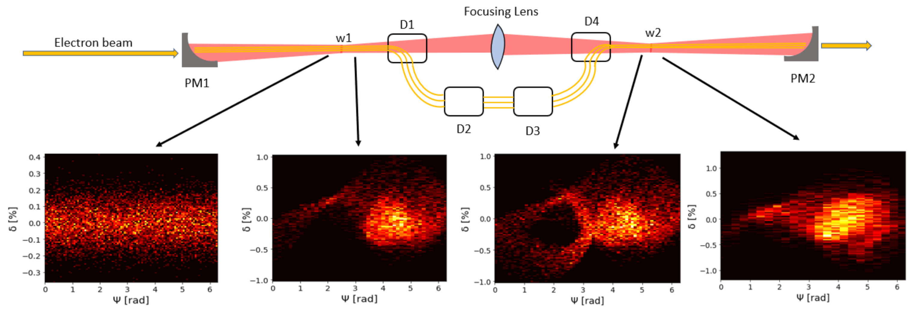
We consider an optical cavity [29] which is the same as in Ref. [27], composed by two Flat Mirrors (FM1, FM2), two Parabolic Mirrors (PM1, PM2) and one focusing lens. The design of such ring cavity is shown in Figure 1.
This design allows obtaining two waists of the laser beam along a straight line, which is as well the direction where an electron beam is injected while counter-propagating with respect to the laser. The electron beam interacts at the first laser waist w 1 and then at the second waist w 2 , with the emission of FEL radiation. The length of the cavity is L c = 2 L l + 2 L s , the long side being L l and the short one L s . A focusing lens is placed between two parabolic mirrors at a distance L l / 2 from both. Denoting with f p the focal length of the parabolic mirrors and with f l the focal length of the central focusing lens, the relative distance between one laser waist and the central focusing lens is d = 2 f l . Furthermore, the following equation must hold L l = 2 f p + 4 f l . After the first interaction the electron beam passes through the magnetic chicane (composed by the four dipoles D1, D2, D3, D4) during the time T m c , finally reaching the second interaction point. This time must be synchronized to the laser pulse in such a way that the two beams can “meet” at the waist w 2 , in formulas we obtain c T m c = 2 f p + 2 L s + L l , with c the speed of light in vacuum. The strength parameter of the wave undulator is defined as:
a 0 = λ 0 e E p 2 π m c 2
where e is the elementary charge, m is the electron’s mass and λ 0 is the period of the wave undulator. The peak electric field E p associated with the laser can be expressed in terms of the laser intensity at the waist:
E p = 2 Z 0 I p
where the vacuum impedance has been denoted as Z 0 and I p is the laser peak intensity calculated as I p = P L / π w 0 2 where P L is the peak power of the laser.

3. Solution of the Liouville Equation for Longitudinal Beam Dynamics in Magnetic Chicanes

In this section, we develop the theory that will be used to calculate the phase-space evolution of the electron beam passing from the first to the second interaction point through the magnetic chicane, as shown in Figure 2 at the end of this section. We study the longitudinal dynamics of relativistic electron beams in magnetic chicanes [28,30]. The traveling direction is denoted by z. The 1D Liouville equation describing the evolution of the longitudinal phase-space of an electron beam is:
ρ d t ( z , p z ; t ) = L ^ ρ ( z , p z ; t )
where ρ is the longitudinal phase-space density, p z is the electron longitudinal momentum and the expression of the Liouville operator is:
L ^ = H z p z H p z z
The Hamiltonian function has been denoted as H and the respective Hamilton equations are:
d p z d t = H z = F z d z d t = H p z = v z
where F z is the longitudinal force acting on the electrons and v z = p z / γ m c the longitudinal velocity, with γ the Lorentz factor of the particle. Equation (3) admits the integral solution:
ρ ( z , p z ; t ) = e 0 t d t L ^ ρ ( z , p z ; 0 )
Equation (6) states that the action of the exponential operator exp ( 0 t d t L ^ ) on the phase-space density ρ at the initial time t = 0 yields the phase-space density at time t. Moreover, using Equation (5), Equation (6) can be further reduced to a more explicit form:
ρ ( z , p z ; t ) = e 0 t d t F z p z 0 t d t v z z ρ ( z , p z ; 0 ) = ρ z 0 t d t v z , p z 0 t d t F z ; 0
Indeed, in Equation (7) we have used the definition of unitary displacement-operator for both the coordinate and the momentum subspaces [30]. The power of this solution lays in the fact that the knowing the single-particle dynamics allows for a complete description of the whole beam in the phase-space at any time. A magnetic chicane consists of dipole magnets usually with the same field-strengths and magnetic lengths. For the study of the recirculated wave undulator under consideration it is preferable to exploit the ponderomotive phase-energy deviation ( ψ δ ) space instead than the coordinate-momentum space ( z p z ), where δ = ( γ γ r ) / γ r with γ r the Lorentz factor of the reference particle (the one with energy equal to the beam average energy). The meaning of the ponderomotive phase ψ will be clearer in Section 5, where the 1D FEL theory is presented. The transformation matrix associated with a magnetic chicane composed by four dipoles, up to the second-order in the energy deviation, reads:
ψ δ = 1 2 π λ 0 R 56 0 1 ψ 0 δ 0
where
R 56 = 4 L sin θ tan θ θ + 2 d tan θ 2 cos θ
is the linear longitudinal dispersion, θ is bending angle, d is distance between the dipoles and L is the dipole length [31]. These transformations are useful to express the dynamical shifts of the phase-space density:
Δ ψ = 2 π λ 0 R 56 δ 0 , Δ δ = 0 ,
The longitudinal phase-space density at the exit of the magnetic chicane, say at the time t, is calculated by means of Equations (7) and (10):
ρ ( ψ , δ ; t ) = ρ ( ψ Δ ψ , δ Δ δ ; 0 ) = ρ ψ 2 π λ 0 R 56 δ 0 , δ ; 0
where t = 0 is the time of entrance into the chicane.

4. Dynamics of Relativistic Electrons Inside an Electromagnetic Undulator

In this section, we calculate the electron trajectories from first principles of relativistic mechanics when they interact with an electromagnetic plane wave. The formalism of Hamilton-Jacobi will be adopted here, as in [32]. The four-dimensional form of Hamilton-Jacobi equation for the interaction of our interest is:
g i k S x i e c A i S x k e c A k = m 2 c 2
where g i k is the Minkowski tensor with ( 1 , 3 ) signature, S the Hamilton function, x i the radius four-vector. We make explicit the planar symmetry in the argument of the four-vector potential by setting A i A i ( ξ ) , with ξ = k i x i = ω 0 ( t + z / c ) , where the sign + in the phase expression stands for the head-on interaction on the z-direction; then we impose the Lorentz gauge condition:
A i x i = A i ξ k i = 0
that is equivalent to A i k i = 0 . To find the Hamilton principal function, we look for a solution of the kind:
S = p i x i + F ( ξ )
where p i is the four-vector who satisfies the condition p i p i = m 2 c 2 , and F ( ξ ) is an unknown function to determine. Substituting (14) into (12) yields:
2 η F ξ + 2 e c p i A i e 2 c 2 A i A i = 0
where η = p i k i . From the above we can infer the expression for F and therefore for S:
S = p i x i e p i η A i d ξ + e 2 2 η A i A i d ξ
Being k i = ( ω 0 / c , 0 , 0 , ω 0 / c ) with ω 0 = 2 π c / λ 0 , we obtain η = ( ω 0 / c ) p 0 + p 3 . Expanding the square of p i , we obtain p 0 2 p 3 2 p 0 2 = m 2 c 2 , where we have denoted by p 0 the modulus of the generalized transverse four-momentum: p 0 is a constant of motion, and it will be naturally interpreted as the electron initial transverse moment just before impacting on the photons. It is straightforward to deduce at this point the following equation:
p 0 p 3 = ω 0 c p 0 2 + m 2 c 2 η
Now, by means of the algebra below:
p 3 x 3 p 0 x 0 = ( p 3 + p 0 ) ( x 3 x 0 ) 2 + ( p 3 p 0 ) ( x 3 + x 0 ) 2
and using Equations (16) and (17), one obtains the following expression for S:
S = p 0 · r c η 2 ω 0 ( c t z ) p 0 2 + m 2 c 2 2 η ξ e p i η A i d ξ + e 2 2 η A i A i d ξ
By equating the S derivatives with respect to the p 0 components and to the η parameter to zero, valid for a suitable choice of reference frame, we achieve the useful results for the electron trajectories:
r = p 0 η ξ + e η A d ξ z = c 2 ω 0 p 0 2 + m 2 c 2 2 η 2 ω 0 c ξ ω 0 e c η 2 p 0 · A d ξ + ω 0 e 2 2 c η 2 A i A i d ξ
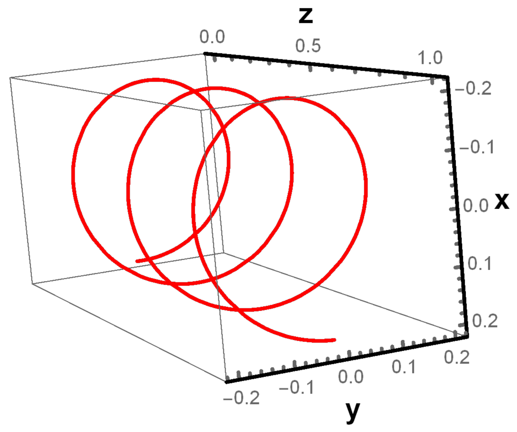
Carrying out the time derivative S / t = γ ( t ) m c 2 , yields an expression for the invariant η , evaluated at the origin of times: η = ω 0 / c γ 0 m c + p z 0 , with γ 0 the initial Lorentz factor. Equations (20) describe the motion of a free electron under the influence of the wave undulator. In the case of a circularly polarized wave undulator the electron trajectory is of the kind shown in Figure 3, obtained plotting Equation (20) for arbitrary parameters to provide a visual example.

5. 1D FEL Equations

In the most of relevant cases p z 0 γ 0 m c , we obtain η = 2 γ 0 ω 0 m . Thus, the electron laws of motion can be recast into:
r = λ 0 4 π θ 0 ξ + λ 0 4 π 1 γ 0 a 0 d ξ z = λ 0 4 π 1 1 + γ 0 2 θ 0 2 2 γ 0 2 ξ λ 0 8 π θ 0 γ 0 · a 0 d ξ + λ 0 16 π 1 γ 0 2 a 0 2 d ξ
where θ 0 is the vector representing the initial divergence of the electron. For sake of simplicity in this paper we focus on the 1D FEL model, justified by the condition θ 0 < < 1 for any electron, i.e., low-divergence beams at the interaction region. Moreover, we consider a 0 < < 1 and γ 0 > > 1 . The laws of motion can be further simplified into:
r λ 0 4 π 1 γ 0 a 0 d ξ z λ 0 4 π ξ
Given the above equations of motion, and choosing a circularly polarized vector potential, the one-dimensional FEL equations are finally (see Appendix A for the derivation):
d E d z = e a 0 4 π ε 0 γ r n e e i ψ j d ψ j d z = 4 π λ 0 δ j d δ j d z = e a 0 4 γ r 2 m c 2 E ( z ) e i ψ j + E * ( z ) e i ψ j
where we have introduced the ponderomotive phase ψ j = ω z / c + ξ j ( ω 0 + ω ) t + ϕ j , i.e., the coordinate identifying the longitudinal position of a particle inside a bucket of physical size determined by the radiation wavelength λ r λ 0 / 2 γ r 2 . ϕ j is an arbitrary initial phase, and we have defined the relative energy deviation δ j of an arbitrary j-particle with Lorentz factor γ j :
δ j = γ j γ r γ r = Δ γ j γ r
The particles’ density of the electron bunch has been denoted as n e . An important quantity has been introduced as well, which is the bunching factor:
b = e i ψ j
where the angular brackets indicate the average over the electron ensemble composing one FEL bucket (more details in Appendix A). The strength parameter K associated with a circularly polarized wave undulator of intensity I p and wavelength λ 0 , in practical units reads:
K = a 0 = 0.85× 10 5 λ 0 [ m ] I p ( W / m 2 )
The choice made in this paper of using a circularly polarized wave undulator is based on the fact that doing so, the strength parameter ( a 0 ) is increased with respect to the case of a linearly polarized wave undulator ( a 0 / 2 ).

6. Discussions on the Recirculated Wave Undulator FEL Scheme

As already discussed and demonstrated in Ref. [27], a CO 2 laser ( λ 0 = 10.6 μm), with an intensity I p = 4.2× 10 18 W/m 2 , corresponding to an energy per pulse of 40 J delivered in 300 p s ( P L = 130 GW) over an effective area Σ 0 = π w 0 2 π × 10 8 m 2 would be enough to provide a wave undulator with sufficiently large K to support the FEL SASE operation [33,34,35]. The value for the strength parameter under these operational conditions is K 0.186 . This K value is too low for standard FEL, but sufficiently high for the emission of coherent radiation in the wave undulator scheme. The energy for the electron beam we consider is around 35 MeV corresponding to a γ r 70 . We choose an electron current value I e = j e Σ e = 3 kA, where Σ e = 0.075 Σ 0 , which means that the electron beam is focused more tightly than the laser beam: this can allow a greater output flux of X-ray photons and eases the spatial overlap of the two beams practically speaking. Moreover, the initial relative energy spread is 10 4 . Even if the considered energy of the electron beam is quite low and the beam focusing rather tight, space charge effects can be neglected. The extension of the interaction region Z i is evaluated as the minimum between two times the Rayleigh length Z R = π w 0 2 / λ 0 and the laser pulse length c τ where τ is the FWHM pulse duration. In formulas:
Z i = m i n c τ , 2 Z R
In our case 2 Z R / c τ < < 1 , so the interaction region is determined by the Rayleigh length. The number of periods per wave undulator both in the waist w 1 and w 2 are 2 Z R / λ 0 , which is many hundreds. As anticipated in the previous section, the working principle of the compact FEL based on the wave undulator is the following: the electron beam is injected into the ring cavity interacting at the laser waists w 1 and w 2 . The electron bunches are microbunched at the radiation wavelength’s period which is in our case λ r 1 nm, falling in the soft X-ray region. When this occurs, coherent radiation power is emitted. A further and important aspect to discuss is the interaction between the electron beams and the wakefields in the machine. The laser can circulate in the ring cavity and interact with the electrons thanks to hollow parabolic mirrors, while the beam passing through the holes generates wakefields (only the first mirror encountered by the electron beam is significant). Given the shortness of the electron bunches considered here, a single bunch of electrons might be not able to efficiently interact with the wakefields. On the other hand, the wakefields might interact with trailing bunches for a certain time structure of the electron bunches in the machine. For facing this issue, the use of dielectric mirrors to suppress the effect of wakefields might be more favorable than metallic-coated optics. Furthermore, for the parameters considered here, the laser diameter at the hollow parabolic mirror is expected to be about 10 cm, therefore the hole would not need to be extremely small.

7. Coherent Synchrotron Radiation

To take into account for the Coherent Synchrotron Radiation (CSR) emitted in the magnetic chicane and to which extent this affects the longitudinal electron beam dynamics, the longitudinal phase-space density at the exit of the magnetic chicane must be expressed with a correction term:
ρ ( ψ , δ ; t ) = ρ ( ψ Δ ψ , δ Δ δ ; 0 ) = ρ ψ 2 π λ 0 R 56 δ 0 , δ κ δ 0 ; 0
which is different than Equation (11) because of the factor κ which explains the relative energy losses due to the emission of CSR. The synchrotron radiation spectrum at low frequencies is proportional to the ω 1 / 3 where ω is the angular frequency of the photons. The total CSR energy E C S R emitted by a bunch with gaussian envelope over one full circle is calculated as:
E C S R = N e 2 e 2 4 π ε 0 c e ω 2 τ e 2 ω R c 1 / 3 d ω = Γ 2 3 N e 2 e 2 8 π ε 0 c τ e R c τ e 1 / 3
where Γ ( x ) is the Gamma function, τ e is the rms electron bunch length, N e is the number of electrons in the bunch and R is the bending radius. The total beam energy is calculated as E b e a m = N e γ r m c 2 . The CSR correction is therefore found to be:
κ = E C S R E b e a m = 4 θ 2 π Γ 2 3 N e e 2 8 π ε 0 τ e γ r m c 3 R c τ e 1 / 3
where the factor 4 θ / 2 π takes into account for the fact that the CSR emitted in the four bending magnets composing the chicane corresponds to a total bending angle which is smaller than the full circle. For a better evaluation of the κ parameter the microbunching should be taken into account beyond the bunch envelope (in this case gaussian), nevertheless this is not relevant for the design considered here since the critical energy of the synchrotron radiation spectrum falls in a range of frequencies much lower than the microbunching frequency.

8. FEL Radiation: Numerical Simulations

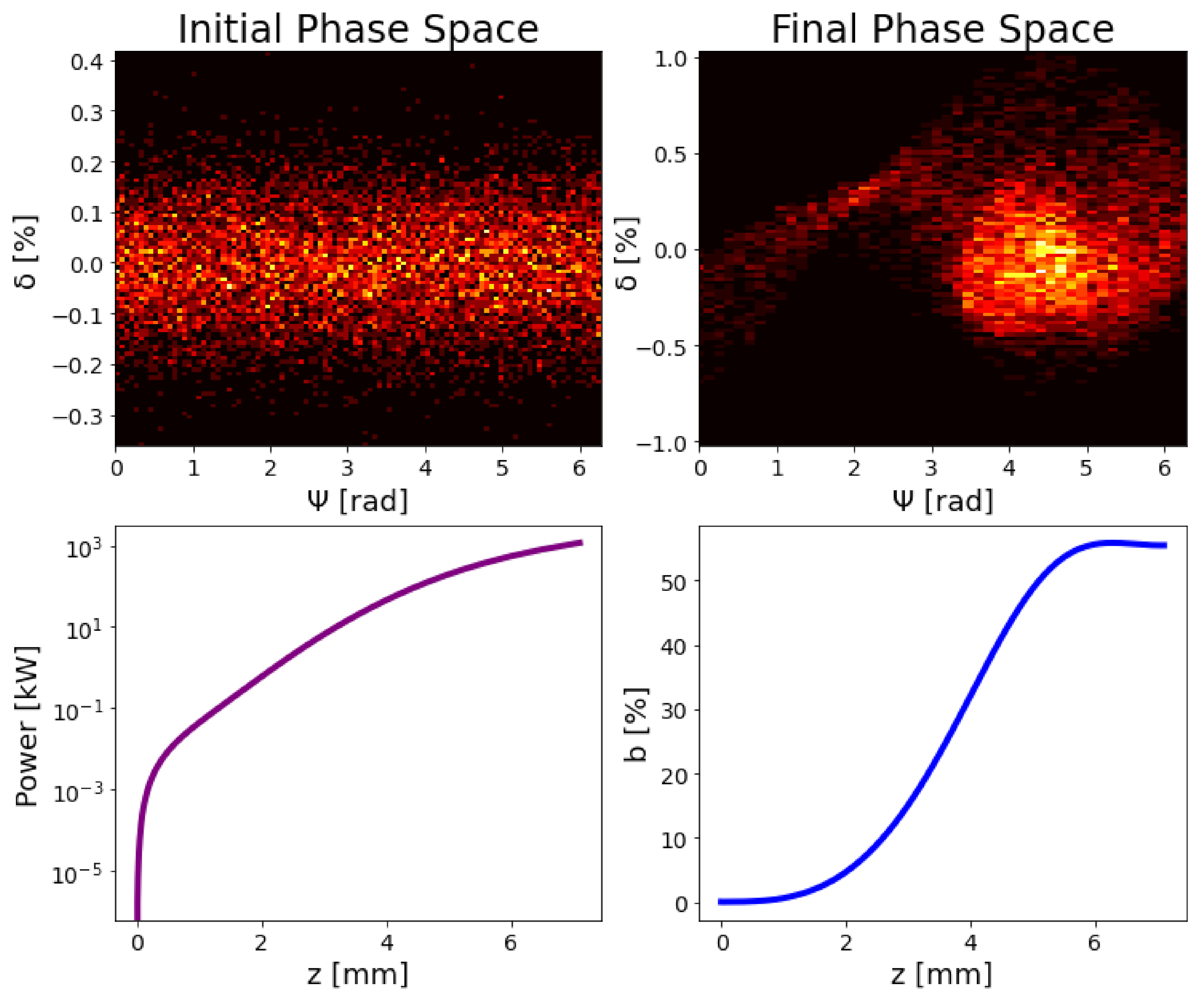
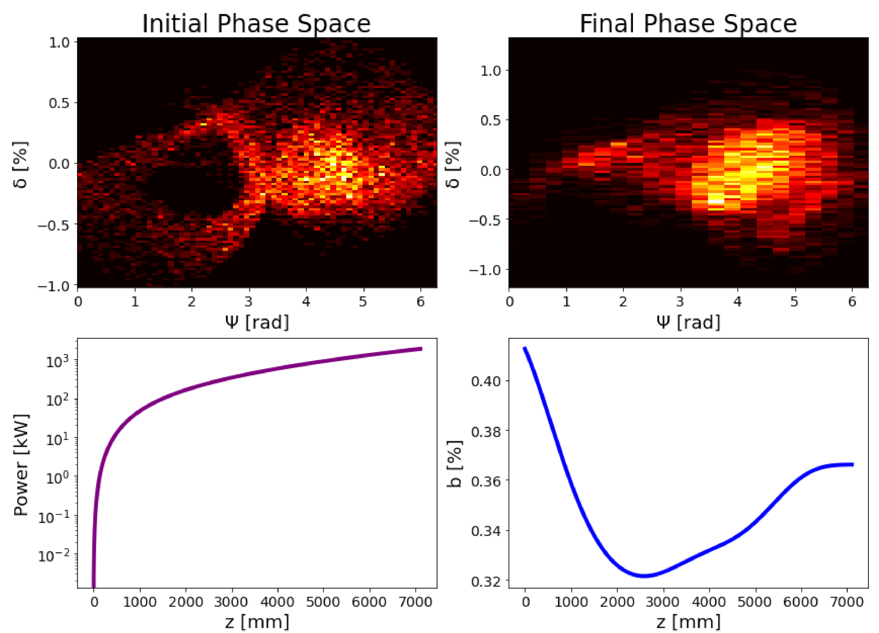
We have developed a numerical code in Python for solving the 1D FEL Equation (23) and to propagate the electron beam from one interaction point to the other self-consistently via Equation (28). This choice has been made (instead of using other available codes) to have more control on the approximations done in the model and in such a way to easily extend it for the forthcoming works where the design will be reconsidered including further effects towards an even more realistic description of the machine. In this section we report on simulation results, in particular showing the longitudinal phase-space evolution of the electron beam while interacting with the electromagnetic undulator and with the magnetic chicane. The parameters used for the chicane considered in this paper are L c = 2.1 m, f p = 150 mm, f l = 300 mm, L s = 150 mm, B = 1.16 T and θ = 72 . The chosen length of the dipoles has been d = 200 mm and the reciprocal distance L = 100 mm. Considering an electron bunch of duration 300 fs and charge 1 n C the correction due to CSR is κ = 1.6% , which is not fully negligible, and it has been implemented in the Python code. The effect of the energy losses due to CSR in the magnetic chicane onto the bandwidth of the wave undulator FEL spectrum is not the main goal of the present paper, but it shall be addressed in a future work. The first result is given in Figure 4, showing the randomly distributed initial longitudinal phase-space relative to one bucket of ponderomotive phase (top-left), the bunched longitudinal phase-space after the interaction with the laser at the waist w 1 of Figure 1 (top-right), the emitted FEL power during the interaction with the CO 2 laser over one Rayleigh length (bottom-left), and finally the evolution of the bunching factor over the same length (bottom-right). The pixel level in the top-left and top-right figure is in arbitrary units but the two plots are normalized on the same scale.
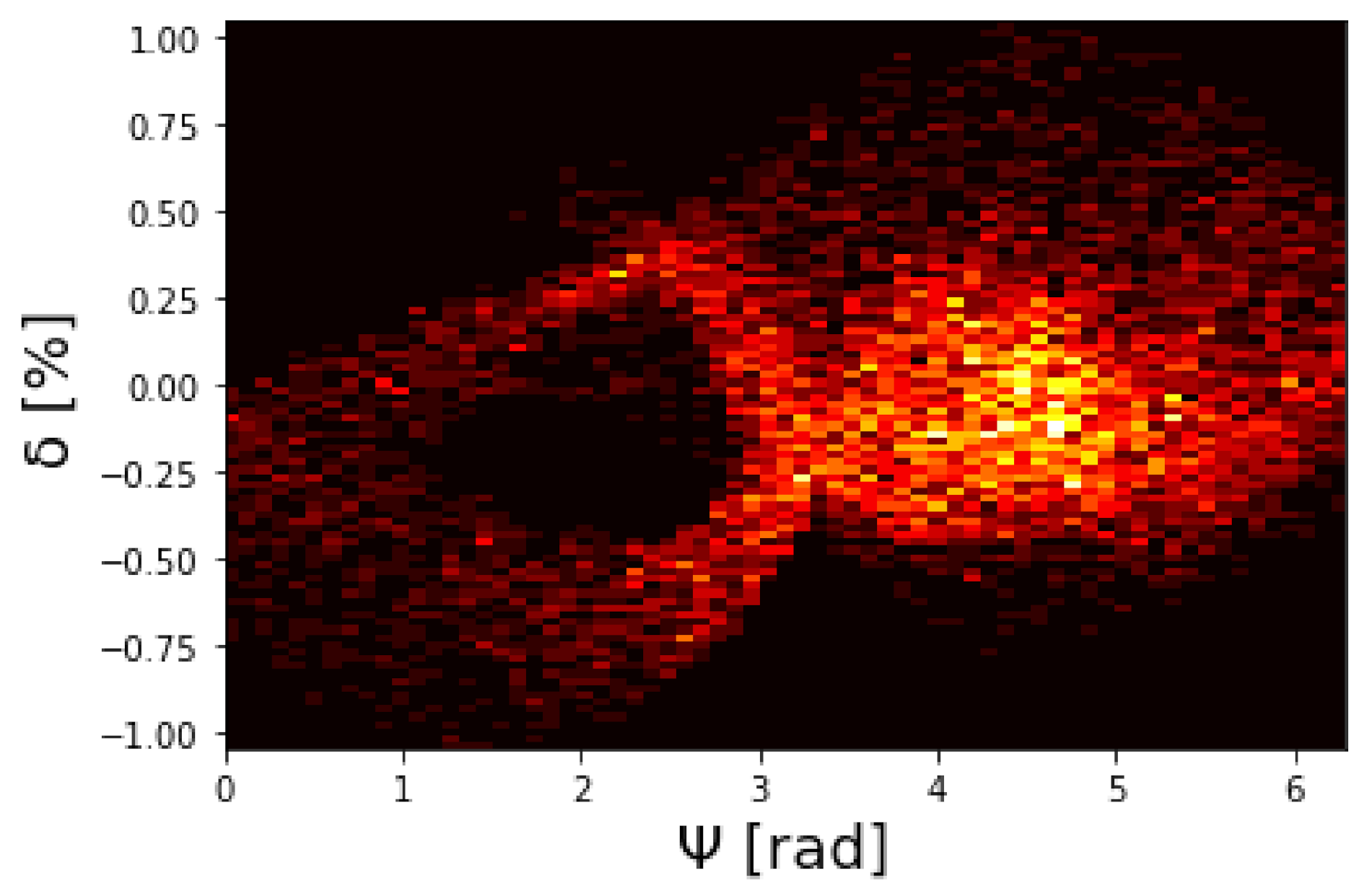
Figure 5 shows the longitudinal phase-space of the electron beam after passing through the magnetic chicane. In order to calculate it, the top-right phase-space of Figure 4 has been propagated according to Equation (28), i.e., for every particle individuated by the pair ( ψ , δ ) the relative energy deviation has been shifted due to CSR and the ponderomotive phase has been shifted by a quantity depending on the element R 56 . The result is shown in Figure 5, where it is possible to observe that the electron microbunching is preserved to some extent. The last simulation result is reported in Figure 6, showing the same distribution in Figure 5 (top-left), the bunched longitudinal phase-space after the interaction with the laser at the waist w 2 of Figure 2 (top-right), the emitted FEL power during the interaction with the CO 2 laser over one Rayleigh length (bottom-left), and finally the evolution of the bunching factor over the same length (bottom-right). The second interaction is evidently more efficient in terms of the FEL power emitted. This is essentially due to the preservation of some order in the longitudinal phase-space after the magnetic chicane which favors the FEL mechanism at the interaction point w 2 even more than at w 1 . The laser is considered essentially not affected by the roundtrip, since the cavity losses are reasonably supposed negligible. Nevertheless, the presence of two interaction points is overall of great advantage since it increases the average output power. Indeed, the time structure of the FEL radiation is a two-pulse structure, and it is worth noting that the fact of having two interaction points does not affect the peak power, but only the average one.

9. FEL Radiation: Comparison with the Analytic Model

In this section, we finally review a fully analytical approach to the FEL power evolution [27], in order to make a comparison with the numerical approach used above while highlighting the main differences. The FEL intensity evolution is ruled by the so-called Pierce parameter, which, for the purposes of this paper, can be cast in the following form:
ϱ = 8.36× 10 3 γ e j e [ A / m 2 ] λ 0 2 [ m ] K 2 1 / 3
where j e is the electron beam density current. The saturation length can be roughly expressed in terms of a few gain lengths. The “full saturation” condition on the emitted power is usually achieved after several times the gain length, the latter given by:
L g = λ 0 4 π 3 ϱ
The saturation power is:
P F = 2 ϱ P e
where P e = γ r m c 2 j e Σ e / e . As a consequence of the previous equations, the FEL saturated power reads:
P F ( M W ) = 1.7× 10 16 ( γ r ϱ ) 4 I p [ W / m 2 ] λ 0 [ m ] 4 Σ e [ m 2 ]
Beside the scaling formulas above, a more complete and analytic description of the SASE intensity growth can be specified by the following logistic-like function:
P ( z ) = P 0 9 B ( z ) 1 + P 0 9 P F B ( z )
B ( z ) = 2 cosh z L g e z / 2 L g cos π 3 + 3 z L g e z / 2 L g cos π 3 3 z L g
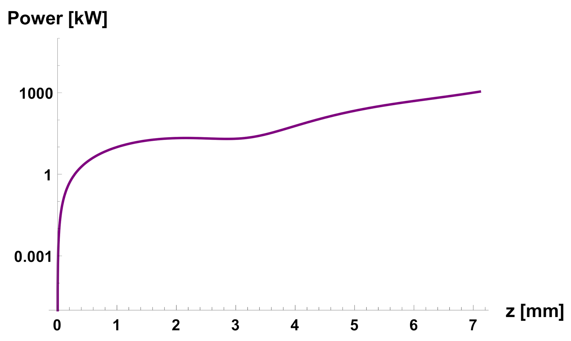
The radiated FEL power analytically calculated by Formulas (35) and (36) under the same operational conditions used for the numerical simulations in Section 8 is shown in Figure 7. For the sake of rigor, Figure 7 should be compared to the bottom-left plot of Figure 4, since it is related to the assumption of no initial correlation (or bunching) in the phase-space. Therefore, the power level and the power trend after the first interaction point analytically calculated is in good agreement with the one numerically simulated. The same cannot be said at the second interaction point, since the pre-bunching preserved after the magnetic chicane makes the analytic model not longer comparable to the bottom-left plot of Figure 6. In conclusion, the above presented analytic model can be used for evaluating the power emitted at the first interaction point, but to be reliable as well at the second interaction point should be generalized to a situation of pre-bunching, which is not in the focus of this paper. In Ref. [27] the FEL emission was studied only analytically and the free parameter P 0 was set to an arbitrarily small value to obtain reasonable output power. On the other hand, in the current paper we have managed to fix this free parameter to a value ( P 0 = 21 kW ) such that the analytic model coincides in terms of final output power with the more rigorous numerical approach. Therefore, here we demonstrate that actually the performance of the proposed design can be higher than the one already shown in [27]. At the same time we show the limitation of the analytic approach, which cannot be used for more than one interaction point (unless for the case that the pre-bunching is completely destroyed by the chicane), since it does not consider the effects related to the pre-bunching.

10. Conclusions

In this paper, we have considered an unconventional scheme of wave undulator FEL. The system we have proposed employs a radiation pulse serving as undulator provided by a high-power laser. A feasibility study has been reported with particular focus on the electron beam dynamics. The device is compact, and the relevant technology will be available in the next future. We have faced the aspects related to the electron beam transport in the wave undulator design previously proposed in Ref. [27]. It has been found that the interaction in the first interaction point is efficient, but the interaction in the second point can be even more efficient provided that the electron beam dynamics in the magnetic chicane is properly controlled to preserve the microbunching to some extent. Conceptual tools for the electron transport have been here provided, also considering losses due to coherent synchrotron radiation. A more realistic design of the whole machine will be topic for a future work, including effects related to the electron beam optics, to the transport of the transverse and longitudinal phase spaces together, to the beam interactions with the wakefields and to the evaluation and optimization of the FEL radiation spectral features.

Funding

This research received no external funding.

Institutional Review Board Statement

Not applicable.

Informed Consent Statement

Not applicable.

Conflicts of Interest

The author declares no conflict of interest.

Appendix A. Derivation of the 1D FEL Equations for the Wave Undulator

The wave equation for the electric field E generated by a current density j is:
1 c 2 2 E t 2 2 E z 2 = μ 0 j t
where the electric field is assumed complex and scalar (this can still cover the case of circular polarization) and the current density is considered along the field polarization direction. With a standard procedure, assuming slowly varying envelope, a forward propagation of the electromagnetic wave and a single-mode oscillation such that t < < c z , Equation (A1) can be reduced to:
E z i μ 0 c 2 ω e i ψ ( t ) j t
In the same framework of assumptions above, we average the current density over a period of rapid oscillation of the radiation field, i.e., within one FEL bucket, while considering γ r > > 1 :
e i ψ ( t ) j t i ω 2 2 π π ω π ω j e i ψ ( t ) d t = i e ω 2 a 0 4 π γ r Σ e j = 1 N e π ω π ω e i ψ ( t ) δ [ z z j ( t ) ] d t i e ω 2 a 0 2 π γ r Σ e j = 1 N e e i ψ ( t j )
where for the last passage we have used the second of Equation (21). We recognize n e = N e ω / Σ e c , therefore:
e i ψ ( t ) j t i ω a 0 n e e c 2 π γ r e i ψ ( t j ) i ω a 0 n e e c 2 π γ r e i ψ j
where N e is the number of electrons in the FEL bucket and the angular brackets denote an average over the particles composing the temporal slice of width 2 π / ω . Thus, the first of Equation (23) is obtained combining Equations (A2) and (A4). The second and third of Equation (23) are the so-called pendulum equations, which are derived as shown below. First, we set the equation for the ponderomotive phase evolution recalling that ω 2 γ r 2 ω 0 :
d ψ j d z = ω c 2 d z j d t + ω 0 c + ω 0 c 2 d z j d t ω 0 + ω c + d ϕ j d z = ( ω + ω 0 ) β j c ω c ω 0 c 1 γ r 2 γ j 2
Since γ r 2 / γ j 2 = ( δ j + 1 ) 2 1 2 δ j for δ j < < 1 , the ponderomotive phase obeys to:
d ψ j d z = ω 0 c 1 γ r 2 γ j 2 2 ω 0 c δ j
which coincides with the second of Equation (23). Concerning the energy deviation:
d δ j d z = 1 γ r d γ j d z = 1 γ r m c 2 d W j d z
Where, by means of the first of Equation (21), the energy exchange rate d W j / d z is given by:
d W j d z = e c d r d t · R e E ( z ) e i ψ j e a 0 2 γ r R e E ( z ) e i ψ j = e a 0 4 γ r E ( z ) e i ψ j + E * ( z ) e i ψ j
Finally, by combining Equation (A8) with Equation (A7) it is possible to obtain the last of Equation (23).

References

  1. O’Shea, P.G.; Freund, H.P. Free-electron lasers: Status and applications. Science 2001, 292, 1853–1858. [Google Scholar] [CrossRef] [PubMed] [Green Version]
  2. McNeil, B.W.; Thompson, N.R. X-ray free-electron lasers. Nat. Photonics 2010, 4, 814–821. [Google Scholar] [CrossRef]
  3. Brau, C.A. Free-electron lasers. Science 1988, 239, 1115–1121. [Google Scholar] [CrossRef] [PubMed] [Green Version]
  4. Barletta, W.A.; Bisognano, J.; Corlett, J.N.; Emma, P.; Huang, Z.; Kim, K.J.; Lindberg, R.; Murphy, J.B.; Neil, G.R.; Nguyen, D.C.; et al. Free electron lasers: Present status and future challenges. Nucl. Instrum. Methods Phys. Res. Sect. A Accel. Spectrometers Detect. Assoc. Equip. 2010, 618, 69–96. [Google Scholar] [CrossRef]
  5. Colson, W.B.; Sessler, A.M. Free electron lasers. Annu. Rev. Nucl. Part. Sci. 1985, 35, 25–54. [Google Scholar] [CrossRef]
  6. Allaria, E.; Badano, L.; Bassanese, S.; Capotondi, F.; Castronovo, D.; Cinquegrana, P.; Danailov, M.B.; D’Auria, G.; Demidovich, A.; Monte, R.D.; et al. The FERMI free-electron lasers. J. Synchrotron Radiat. 2015, 22, 485–491. [Google Scholar] [CrossRef]
  7. Schmüser, P.; Dohlus, M.; Rossbach, J.; Behrens, C. Free-Electron Lasers in the Ultraviolet and X-ray Regime; Springer Tracts in Modern Physics; Springer: Berlin/Heidelberg, Germany, 2014; Volume 258. [Google Scholar]
  8. Pellegrini, C.; Marinelli, A.; Reiche, S. The physics of X-ray free-electron lasers. Rev. Mod. Phys. 2016, 88, 015006. [Google Scholar] [CrossRef]
  9. Feng, C.; Deng, H.X. Review of fully coherent free-electron lasers. Nucl. Sci. Tech. 2018, 29, 1–15. [Google Scholar] [CrossRef]
  10. Pellegrini, C. The history of X-ray free-electron lasers. Eur. Phys. J. H 2012, 37, 659–708. [Google Scholar] [CrossRef] [Green Version]
  11. Margaritondo, G.; Rebernik Ribic, P. A simplified description of X-ray free-electron lasers. J. Synchrotron Radiat. 2011, 18, 101–108. [Google Scholar] [CrossRef] [Green Version]
  12. Curcio, A.; Dattoli, G.; Di Palma, E.; Petralia, A. Free electron laser oscillator efficiency. Opt. Commun. 2018, 425, 29–37. [Google Scholar] [CrossRef]
  13. Honkavaara, K. Status of the FLASH FEL User Facility at DESY. In Proceedings of the 38th International Free Electron Laser Conference, Santa Fe, NM, USA, 20–25 August 2017. [Google Scholar]
  14. Rönsch-Schulenburg, J.; Honkavaara, K.; Schreiber, S.; Treusch, R.; Vogt, M. FLASH-Status and Upgrades. In Proceedings of the 39th International Free Electron Laser Conference (FEL’19), Hamburg, Germany, 26–30 August 2019. [Google Scholar]
  15. Corde, S.; Phuoc, K.T.; Lambert, G.; Fitour, R.; Malka, V.; Rousse, A.; Beck, A.; Lefebvre, E. Femtosecond X rays from laser-plasma accelerators. Rev. Mod. Phys. 2013, 85, 1–58. [Google Scholar] [CrossRef]
  16. Esarey, E.; Shadwick, B.A.; Catravas, P.; Leemans, W.P. Synchrotron radiation from electron beams in plasma-focusing channels. Phys. Rev. E 2002, 65, 056505. [Google Scholar] [CrossRef] [Green Version]
  17. Aschikhin, A.; Behrens, C.; Bohlen, S.; Dale, J.; Delbos, N.; Di Lucchio, L.; Elsen, E.; Erbe, J.-H.; Felber, M.; Foster, B.; et al. The FLASHForward facility at DESY. Nucl. Instrum. Methods Phys. Res. Sect. A Accel. Spectrometers Detect. Assoc. Equip. 2016, 806, 175–183. [Google Scholar] [CrossRef] [Green Version]
  18. Dobsiach, P.; Meystre, P.; Scully, M.O. Optical wiggler free-electron X-ray laser in the 5 Å region. IEEE J. Quantum Electron. 1983, 19, 1812–1820. [Google Scholar] [CrossRef]
  19. Ciocci, F.; Dattoli, G.; Walsh, J. A short note on the wave-undulator FEL operation. Nucl. Instrum. Methods A 1985, 237, 401–403. [Google Scholar] [CrossRef]
  20. Banacloche, J.G.; Moore, G.T.; Schlicher, R.R.; Scully, M.O.; Walther, H. Soft X-Ray freeelectron laser with a laser undulator. IEEE J. Quantum Electron. 1987, 23, 1558–1570. [Google Scholar] [CrossRef]
  21. Tang, C.M.; Hafizi, B.; Ride, S.K. Thomson backscattered X-rays from an intense laser beam. Nucl. Instrum. Methods A 1993, 331, 371–378. [Google Scholar] [CrossRef]
  22. Dattoli, G.; Letardi, T.; Vazquez, L.R. FEL SASE WAVE undulators. Opt. Commun. 2012, 285, 5341–5346. [Google Scholar] [CrossRef]
  23. Bacci, A.; Ferrario, M.; Maroli, C.; Petrillo, V.; Serafini, L. Transverse effects in the production of x rays with a free-electron laser based on an optical undulator. Phys. Rev. Spec. Top.-Accel. Beams 2006, 9, 060704. [Google Scholar] [CrossRef] [Green Version]
  24. Polyanskiy, M.N.; Pogorelsky, I.V.; Yakimenko, V. Picosecond pulse amplification in isotopic CO2 active medium. Opt. Express 2011, 19, 7717–7725. [Google Scholar] [CrossRef] [PubMed]
  25. Bazarov, I.V.; Dunham, B.M.; Sinclair, C.K. Maximum achievable beam brightness from photoinjectors. Phys. Rev. Lett. 2009, 102, 104801. [Google Scholar] [CrossRef] [PubMed] [Green Version]
  26. Dattoli, G.; Petrillo, V.; Rau, J.V. FEL SASE and wave-undulators. Opt. Commun. 2012, 285, 5341–5346. [Google Scholar] [CrossRef]
  27. Curcio, A.; Dattoli, G.; Ferrario, M.; Giulietti, D.; Nguyen, F. An optical cavity design for a compact wave-undulator based-FEL. Opt. Commun. 2017, 405, 197–200. [Google Scholar] [CrossRef]
  28. Curcio, A.; Panas, R.; Knafel, M.; Wawrzyniak, A.I. Liouville theory for fully analytic studies of longitudinal beam dynamics and bunch profile reconstruction in dispersive lines. Nucl. Instrum. Methods Phys. Res. Sect. A Accel. Spectrometers Detect. Assoc. Equip. 2021, 986, 164755. [Google Scholar] [CrossRef]
  29. Svelto, O. Principles of Lasers; Plenum Press: New York, NY, USA, 1976; p. 386. [Google Scholar]
  30. Babusci, D.; Dattoli, G.; Quattromini, M. Relativistic equations with fractional and pseudodifferential operators. Phys. Rev. A 2011, 83, 062109. [Google Scholar] [CrossRef] [Green Version]
  31. Di Mitri, S. Bunch length compressors. CERN Yellow Rep. Sch. Proc. 2018, 1, 363. [Google Scholar] [CrossRef]
  32. Landau, L.D. (Ed.) The Classical Theory of Fields; Elsevier: Amsterdam, The Netherlands, 2013; Volume 2. [Google Scholar]
  33. Dattoli, G.; Ottaviani, P.L.; Pagnutti, S. Nonlinear harmonic generation in high-gain free-electron lasers. J. Appl. Phys. 2005, 97, 113102. [Google Scholar] [CrossRef]
  34. Dattoli, G.; Ottaviani, P.L.; Pagnutti, S. Booklet for FEL Design; ENEA-Edizioni Scientifiche: Frascati, Italy, 2007. [Google Scholar]
  35. Lau, Y.Y.; He, F.; Umstadter, D.P.; Kowalczyk, R. Nonlinear Thomson scattering: A tutorial. Phys. Plasmas 2003, 10, 2155–2162. [Google Scholar] [CrossRef] [Green Version]
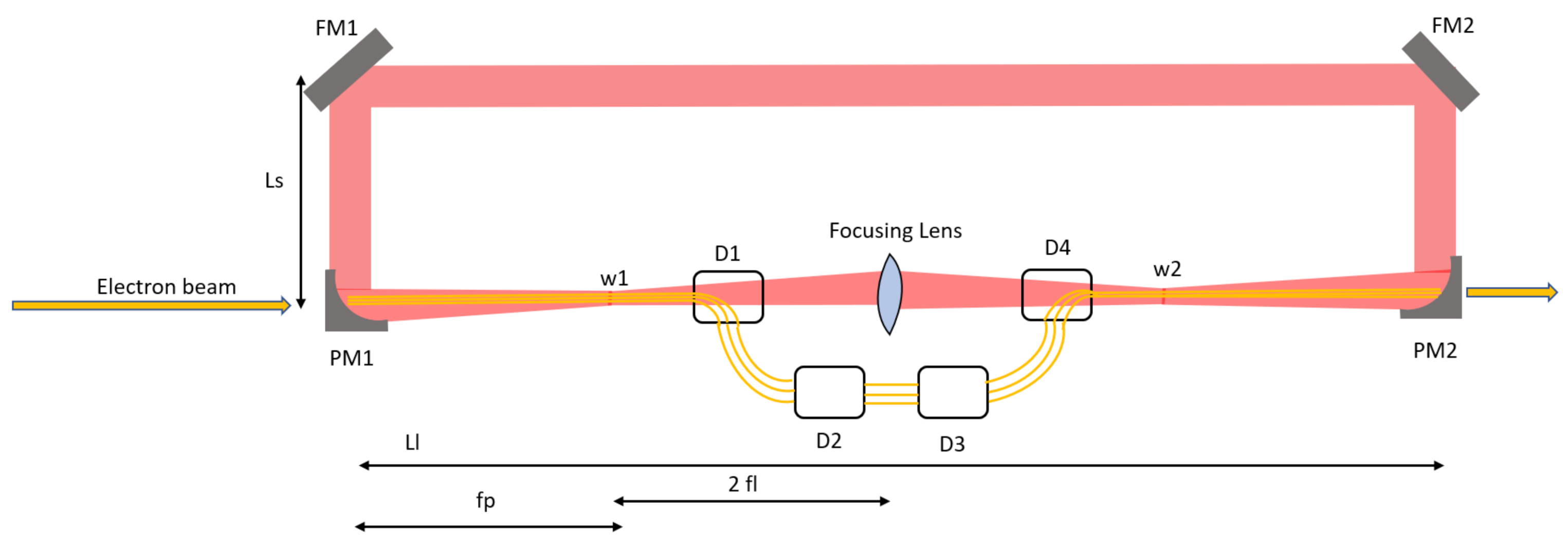
Figure 1. Design of the ring cavity for the wave undulator. The laser circulates clockwise.
Applsci 11 05936 g001
Figure 2. Evolution of the longitudinal phase-space of the electron beam passing from one interaction point to the other. The evolution through the magnetic chicane is calculated via the analytic solution of the Liouville equation. The longitudinal phase spaces shown above will be commented in Section 8.
Applsci 11 05936 g002
Figure 3. Electron trajectory in a circularly polarized wave undulator (arbitrary units).
Applsci 11 05936 g003
Figure 4. Simulation results with FEL1D code in Python, concerning the first interaction point of Figure 2.
Applsci 11 05936 g004
Figure 5. Simulation results with FEL1D code in Python, at the entrance of the second interaction point.
Applsci 11 05936 g005
Figure 6. Simulation results with FEL1D code in Python, after the second interaction point.
Applsci 11 05936 g006
Figure 7. The FEL radiated power versus the propagation distance inside of the wave undulator.
Applsci 11 05936 g007
Publisher’s Note: MDPI stays neutral with regard to jurisdictional claims in published maps and institutional affiliations.