Article

Subcooled Flow Boiling Heat Flux Enhancement Using High Porosity Sintered Fiber

1
Department of Mechanical and Intelligent System Engineering, The University of Electro-Communications, 1-5-1 Chofugaoka, Chofu, Tokyo 182-8585, Japan
2
Central Research Institute, Mitsubishi Materials Co., Ltd., 1-600 Kitabukurocho, Omiya, Saitama 330-0835, Japan
*
Author to whom correspondence should be addressed.
Appl. Sci. 2021, 11(13), 5883; https://doi.org/10.3390/app11135883
Submission received: 19 May 2021 / Revised: 21 June 2021 / Accepted: 23 June 2021 / Published: 24 June 2021
(This article belongs to the Special Issue Sciences and Innovations in Heat Pump/Refrigeration: Volume II)

Abstract

:
Passive methods to increase the heat flux on the subcooled flow boiling are extremely needed on modern cooling systems. Many methods, including treated surfaces and extended surfaces, have been investigated. Experimental research to enhance the subcooled flow boiling using high sintered fiber attached to the surface was conducted. One bare surface (0 mm) and four porous thickness (0.2, 0.5, 1.0, 2.0 mm) were compared under three different mass fluxes (200, 400, and 600 kg·m−2·s−1) and three different inlet subcooling temperature (70, 50, 30). Deionized water under atmospheric pressure was used as the working fluid. The results confirmed that the porous body can enhance the heat flux and reduce the wall superheat temperature. However, higher porous thickness presented a reduction in the heat flux in comparison with the bare surface. Bubble formation and pattern flow were recorded using a high-speed camera. The bubble size and formation are generally smaller at higher inlet subcooling temperatures. The enhancement in the heat flux and the reduction on the wall superheat is attributed to the increment on the nucleation sites, the increment on the heating surface area, water supply ability through the porous body, and the vapor trap ability.

1. Introduction

Several researchers have studied the Boiling heat transfer phenomena due to the large applications on the cooling systems of several industries. In particular, researchers have focused on flow boiling since it presents a high heat transfer rate higher than the pool boiling, promoted by the forced convection. The flow boiling phenomenon is also classified into saturated flow boiling and subcooled flow boiling, where the subcooled flow boiling is characterized by the bulk flow temperature lower than its saturation temperature [1,2,3]. The heat transfer on the subcooled flow boiling is a combination of the single-phase convective and the nucleate boiling. At high heat flux, the heat transfer is essentially attributed by the nucleate boiling and little contribution of the single-phase. The nucleate boiling is identified by the bubble formation [4,5,6,7,8]. In the last decade, the heat flux of new microprocessors, power reactors, fossil boilers, etc., has increased exponentially. High heat flux of between 2 and 3 MW/m2 have been reported, and, in particular, in the case of “on-chip hot spot,” a heat flux of 15 MW/m2 was reported [9]. Due to this increment, researchers have proposed new passive technologies to increase the heat flux on the cooling systems. These techniques include; treated surfaces, rough surfaces, extended surfaces, displaced enhancement devices, swirl flow devices, coiled tubes, surface tension devices, additive for liquids, and additive for gases [10,11]. Copper is the most used material to fabricate the microchannel heat sink due to its higher thermal conductivity, easy machinability, and relatively low production cost [12]. In particular, treated surfaces have been reported to increase the flow boiling heat flux between 20% and 100% in comparison with non-treated surfaces [11,13,14]. Vlachou et al. [15] studied the influence of the channel height, mass flux, and the heated surface roughness, using deionized water as the working fluid. They analyzed the heat transfer rate on an aged copper surface and a polished copper surface, concluding that the heat transfer rate reduces by 10% on the aged copper after 24 h of operation in comparison with the polished surface. They also reported an enhancement between 15–20% on the 3 mm channel height in comparison with the 10 mm channel height at a mass flux of 330 kg/m2s. They attributed the enhancement to the bubble dynamics on the aging surface, the hydrophilic nature on the polished surface and the bubble formation density, and the thermal resistance of the oxidized layer on the aged surface. In 2017, Wang et al. [16] conducted experimental research using a downward face porous honeycomb plate under saturated flow boiling and compared the results with a bare surface and a solid honeycomb plate. Water at saturation temperature under four different flow rates was considered as parameters. The honeycomb is fabricated with stainless steel by a sintering process having a final porosity of 35%. They reported an enhancement of around 2.4 times the critical heat flux (CHF) at a low flow rate (200 kg/m2s) using the porous honeycomb in comparison with the solid honeycomb. However, increasing the flow rate, the critical heat flux tends to reduce. At a flow rate of 1300 kg/m2s, the enhancement was reduced to 1.2 times. The CHF enhancement is attributed to the continuous water supply on the porous honeycomb. On the other hand, on the solid honeycomb, bubbles are generated, and they cover the boiling surface and CHF occurs faster due to the lack of water. At low flow rate conditions, the bubbles generated on the surface coalesce and cover the surface, thus a vapor film would be produced. In general terms, the porous media presents physical characteristics that improve the heat flux on subcooled flow boiling, and three main characteristics are defined. (I) Due to the space between the micro holes or the interconnected fibers, the wetted area and the nucleation sites increase; (II) the lower density and the reduction on the material used on the fabrication, the production cost is reduced; (III) the variety on the fabrication processes make easier to create nano/microstructures [17,18]. Alam et al. [19] conducted a flow boiling heat transfer experiment using deionized water as a working fluid. The flow pattern of the silicon micro gap with three different roughness was analyzed. Results showed that the boiling incipience and bubble formation density increases directly inverse to the roughness. The heat flux on the subcooled flow boiling process is directly related to the inlet subcooling temperature, the flow rate, the system pressure, the physical properties of the working fluid, and the surface conditions. This last parameter has been investigated by several researchers. They studied the bubble behavior and the flow pattern on the porous media and compared with the bare surfaces, recording and analyzing the bubble formation and departure with a high-speed camera [20,21,22,23]. In the last decade, researchers have used copper foam materials to improve heat transfer performance and avoid burning out on heating surfaces. Experimental research using a deep microchannel copper on water flow boiling was performed by Jayaramu et al. [24]. Their results show the influence of the surface characteristics on the amount of heat transfer. The roughness, oxidation, and wettability have a direct relation with the nucleation site density. The wall superheat increased drastically, and the heat flux was reduced on the freshly machined surface. Tang et al. [25] manufactured an interconnected microchannel net with square pores made by copper and tested its flow boiling performance, concluding that the amount of heat transfer in the two-phases region and the pressure drop changes depend on the channel width. In 2020 Manetti et al. [26] performed experimental research using an open-cell copper metal foam with three different thicknesses (3, 2, and 1 mm) on a pool boiling system with HFE-7100 as working fluid. They found that there was not a constant value for the optimum porous thickness, and the enhancement of the porous materials also changed on the low heat flux and high heat flux regions. However, the heat flux performance of the three different porous thicknesses was better in comparison with the plain (bare) surface. They also reported that the bubbles grow and coalescence easily on the high thicknesses porous body, and as a result, the mean bubble diameter increases, covering the heating area. Due to this effect, the heat transfer coefficient decreases. On the other hand, the bubbles on the low porous thickness are concentrated on the top, and they depart easily from the surface, thus the fluid supply keeps constant. In general terms, they found an increment on the heat transfer coefficient of 145% using the porous copper materials in comparison with the bare surface.
The present research describes the experimental investigation on the horizontal subcooled flow boiling using porous media attached to the surface, extending the research and experiments performed by Otomo et al. [27]. The influence of the bubble formation and the flow pattern on the heat flux enhancement is discussed. The goal of the present research is to increase the heat flux using the porous media as a passive method in comparison with the bare surface. Besides, the influence of the mass flux and the inlet subcooling temperature is also discussed.

2. Experimental Setup and Procedure

2.1. Test Loop

The experimental apparatus was similar to that used in [27]. As presented schematically in Figure 1, the experimental apparatus was designed to analyze the subcooled flow boiling heat transfer at a low system pressure. It consisted of a degassing tank with a capacity of 40 L that was installed to store deionized water that was used as the working fluid. A heat exchanger was connected directly to the tank to reduce the working fluid temperature and keep the subcooling conditions. Just after the heat exchanger, a magnetic pump “IWAKI” with a maximum liquid inlet temperature of 80 °C provided the forced convection on the system. A preheater was used to keep constant the inlet subcooling temperature, and the mass flux was regulated by a control valve. An oval Coriolis flow meter monitored the mass flux just before the inlet part of the test section. The water flow was rectified with a porous aluminum body, and the deionized water flowed on the test section. In the inlet and outlet part of the test section, a pressure gauge and a differential pressure gauge were installed, respectively. A proportional integral derivative (PID) controlled the temperature on the test section, and a data logger collected the obtained data. A detailed explanation of the test section was given in Section 2.2.

2.2. Test Section

As shown in Figure 2, the test section was divided into 2 main parts. In the heating section, inside the copper block B, a group of 12 cartridge heaters was installed, and they could provide a maximum heat flux of 2.5 MW/m2. A K-type thermocouple was installed on the center of the copper and connected to the PID controller. Thus, the PID controller keeps the heat flux in steady conditions. Copper block A was assembled to the copper block B using compression screws. The heating surface was also fabricated with cooper, and the final dimension of the block was 50 mm × 100 mm. On the top of the heating surface, a polycarbonate was attached and formed a 10 mm × 10 mm flow channel as shown in Figure 2c. In addition, the properties of the polycarbonate allowed the flow pattern visualization. A total of 10 k-type thermocouples were installed and distributed in 5 groups separated 20 mm between them (Figure 2b), each group of 2 thermocouples had a distance of 9 mm between them, and 1 mm and 10 mm distance concerning the heating surface as shown in Figure 2d. All the thermocouples were connected directly to the data logger to record the temperature on the heating surface. The bubble behavior was recorded with a high-speed camera “Fast mini AX50” at 5000 fps and 1/50,000 shutter speed.

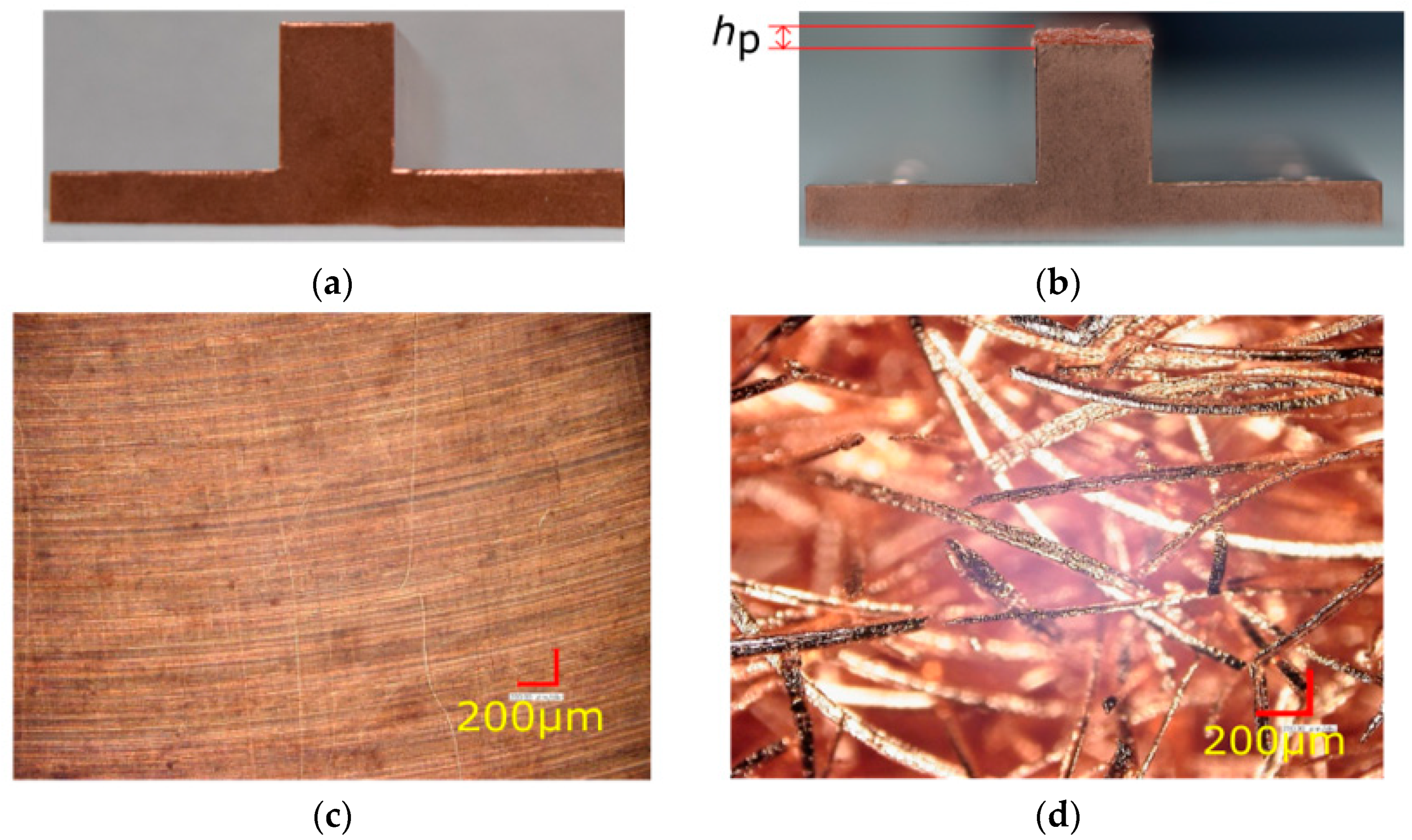
2.3. High Porosity Sintered Fiber

High porosity sintered fiber attached to the surface could both enhance the maximum heat flux and reduce the wall superheat temperature in comparison with the bare surface [24]. Microfibers were attached to the bare surface using the same material by a sintering process, thus, the contact resistance was reduced significantly. The attached sintered fiber created a porous height (hp), as shown in Figure 3b. The bare surface had a roughness of Ra = 0.4 μm. The microfibers had a diameter of 0.06 mm, and the porosity of the porous material was 86%, the highest porosity for this machinated process. A total of 4 different porous height hp, were fabricated (0.2, 0.5, 1, and 2 mm) and 1 bare surface hp = 0 mm. The intertwined fibers increased the wetting area and promoted the nucleation sites. Both the surface and microscopic view are shown in Figure 3.

2.4. High Porosity Sintered Fiber

After 2 h of degassing, the magnetic pump was activated. Deionized water flowed into the channel, then the preheater was activated, and it controlled the inlet subcooling temperature to 50 K and 70 K as parameters. The mass flux was regulated by the control valve and confirmed with the oval Coriolis flow meter. After the mass flux and the inlet temperature became stable, the PID controller was activated, and the group of cartridges provided the heat flux. The copper block B temperature was initially adjusted to 100 °C. Once the temperature measured by the thermocouples became stable, the data were recorded for around 3 min, and a video using the high-speed camera was recorded. Then, the copper block was increased to 40 °C, and the process was repeated until the heat flux limit (around 2.5 MW/m2) provided by the cartridge heaters was reached or the critical heat flux was reached. If the temperature of the heating surface increased abruptly, the CHF conditions were assumed. Detailed information of the experimental parameters is shown in Table 1.

2.5. Uncertainly Analysis

The mass flux measured by the oval Coriolis flow meter was 0.2%. The measurement uncertainly of the k-type thermocouple installed on the copper block B was calculated in 0.05 K and zero contacting point. On the other hand, the group of 10 thermocouples attached to the heating section had a measurement error of 0.2 K.
The heat flux uncertainly measurement was calculated as follows.
q = k c Δ T δ x  
where ΔT is the temperature gradient of each pair of thermocouples, k c is the copper thermal conductivity, and δx represents the distance between the pair of thermocouples. Besides, the uncertainty of the heat flux is calculated as follows.
Δ q = ( q k Δ k ) 2 + ( q δ x Δ δ x ) 2 + ( q T 1 Δ T 1 ) 2 + ( q T 2 Δ T 2 ) 2
Thus, the heat flux error was calculated about 3% and every experiment was conducted twice to confirm the repeatability.

3. Results

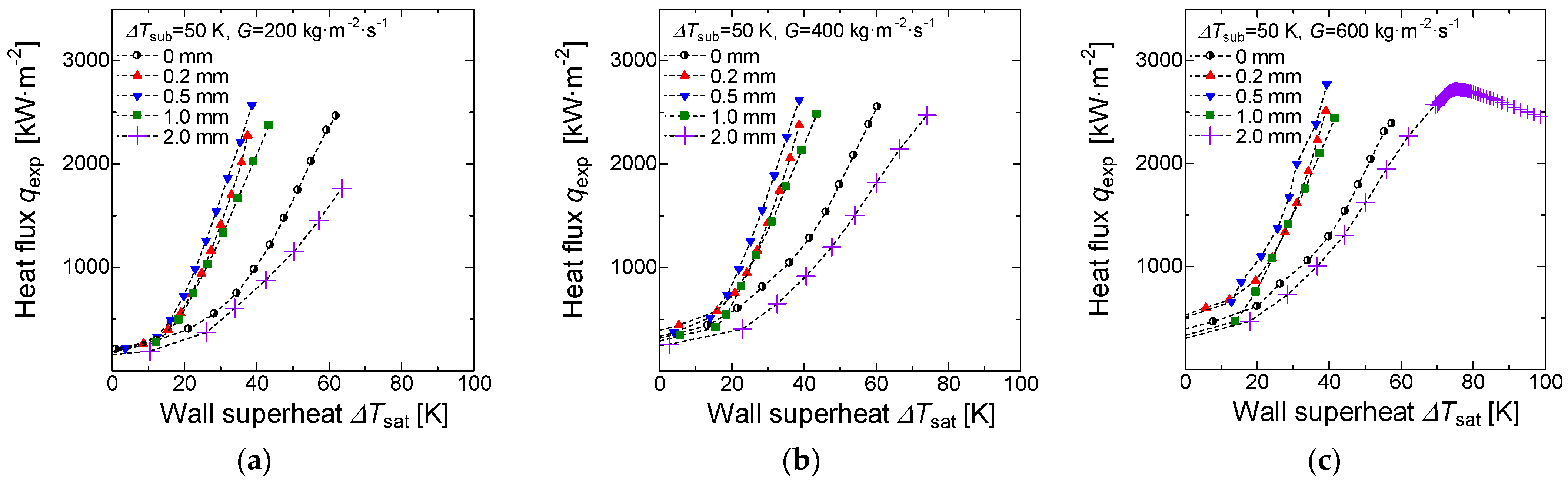
3.1. Boiling Curves under Different Flow Rates and Inlet Subcooling Temperature

Figure 4a–c, show the boiling curve under an inlet subcooling temperature Δ T s u b = 30   K , for all the five different porous thicknesses, at 200, 400, and 600 kg·m−2·s−1, respectively. As expected, the onset nucleate boiling depends on the mass flux and subcooling inlet temperature. For the particular case of the 0 mm at 400 kg·m−2·s−1, the critical heat flux was reached as the increment on the wettability hinders the active nucleation sites and diminishes the vapor trapping ability. In addition, the tendency of the porous effect was visible. The 0.2, 0.5, and 1 mm porous thickness presented an enhancement concerning the 0 mm surface, however, the 2 mm porous thickness performance was lower than the 0 mm. This effect was attributed to the increment in the number of vapor scape channels. The vapor tends to combine and form a big vapor bubble and it hinders the water supply to the heating surface. In Figure 5, convective boiling curves for Δ T s u b = 50   K , and 200, 400, and 600 kg·m−2·s−1are shown. A decrease in the wall superheat was appreciated in comparison with the 0 mm, and the critical heat flux was not reached at low mass fluxes, whereas for the 600 kg·m−2·s−1the critical heat flux on the 2 mm porous thickness was reached at a wall superheat around Δ T s a t = 70   K . For all the three mass fluxes, the 0.5 mm presented the highest heat flux at the same wall temperature. The reduction in the wall superheat was attributed to the increment in the nucleation sites, the number of vapor scape channels, and the wettability. The 2 mm tendency was the same as inlet subcooling temperature Δ T s u b = 30   K , with the difference that a higher inlet subcooling temperature and higher mass flux, the critical heat flux was reached on the 2 mm porous body. Finally, the heat fluxes at inlet subcooling temperature Δ T s u b = 70   K were presented in Figure 6. At high inlet subcooling temperature, the critical heat flux was easily reached on the high thickness body porosity. For the case of the 2 mm thickness, and independently to the mass flux, the critical heat flux was reached. The wall superheat temperature at the critical heat flux was lower at higher mass flux. In Figure 6c, an abrupt increment on the wall superheat was appreciated on the higher porous thickness due to the formation of a vapor blanket inside the porous body.
In general terms, the porous body also increased the heating surface area, the turbulence due to the irregularities on the body, and the thermal resistance was also affected. These three factors need to be considered in the flow boiling process. In addition, the higher thickness porous body increment the number of vapor scape channels, and this effect diminished the water supply to the heating surface. In addition, the bubbles nucleated, departed, and coalesced inside the porous body creating a vapor blanket, thus, the critical heat flux and the vapor film regimen were reached. A lower thickness porous body increased the nucleation sites. Thus the bubble rate formation and departure also increased, meanwhile the working fluid kept the heating surface at a lower temperature.
At low mass fluxes and before the ONB ( Δ T s a t < 20   K ) , the effect of the porous body on the heat transfer was almost marginal. On the other hand, a higher inlet subcooling temperature affects the onset nucleate boiling, and it was shifted to a lower wall temperature.

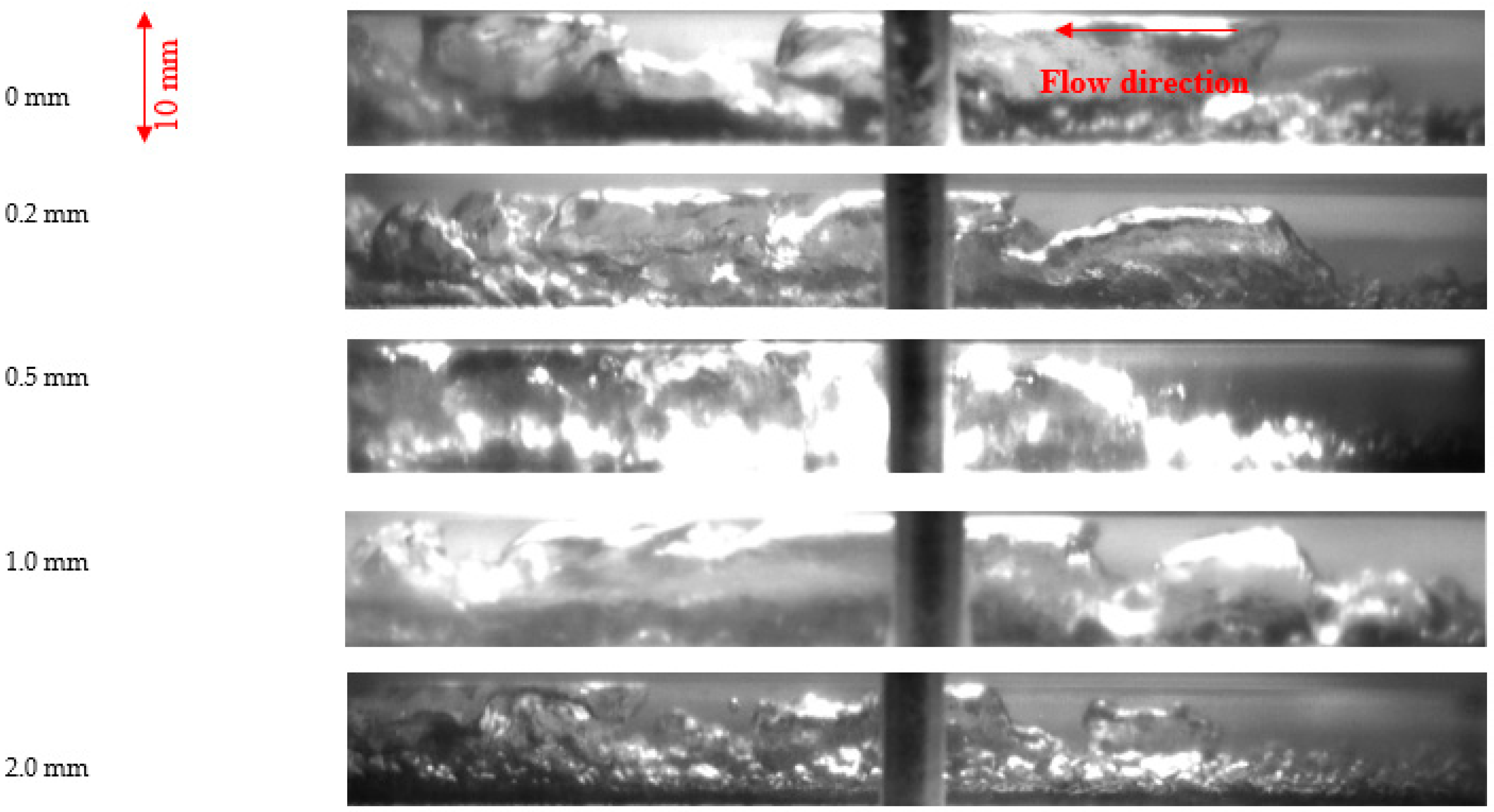
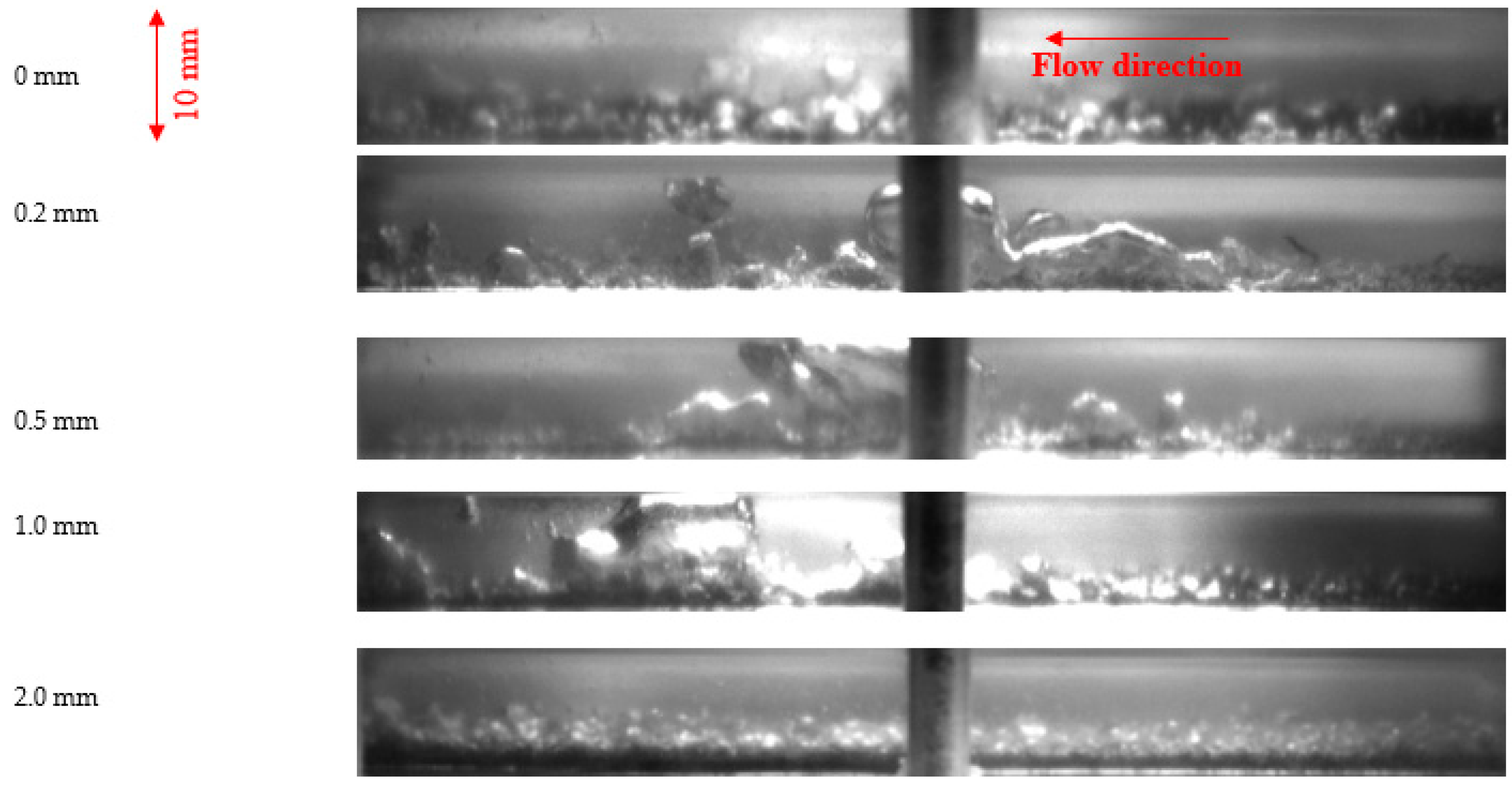
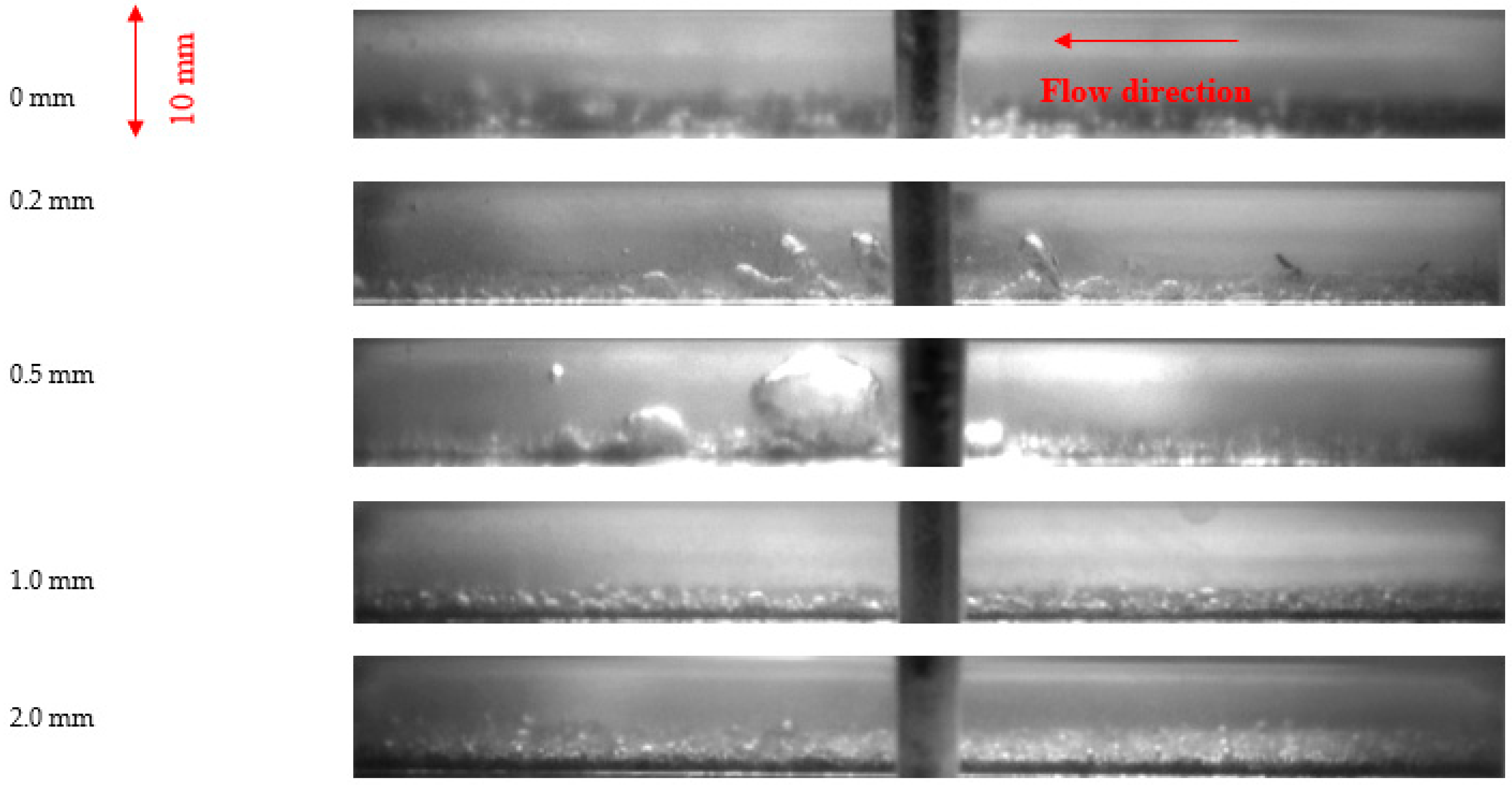
3.2. Flow and Bubble Pattern

Figure 7 shows the boiling flow pattern at the maximum heat flux of each porous thickness, the inlet subcooling temperature Δ T s u b = 30   K , and mass flux 400 kg·m−2·s−1. Except for the 2 mm porous thickness, the small bubbles nucleated, coalescence, and departure forming a big bubble that fully covered the flow channels. In the 2 mm porous thickness, just small bubbles were generated outside the porous body, however, the wall superheat increased considerably. This effect is attributed to the vapor trapping by the microchannels inside the porous body. The critical heat flux was reached on the 0 mm porous thickness. Due to the limited number of cavitation sites, a single big bubble was generated, forming a vapor blanket due to the lack of water supply. The departure rate on the 0 mm surface was lower than that of those on the porous body surfaces. In Figure 8, the flow pattern where the inlet subcooling temperature Δ T s u b = 30   K . In comparison with the inlet subcooling temperature Δ T s u b = 30   K , the flow channels presented a clear reduction in the bubble size formation, and in none of the cases, the CHF was reached. This effect was attributed to the inlet temperature that affects the bulk temperature farthest to the saturation temperature. Under high inlet subcooling temperature, the bubble formation was reduced to small bubbles outside the porous body with a high departure rate. Bubbles rarely coalesce between them, however, the 0.5 mm porous body promoted in higher-level the bubble coalesce and thus, increase the heat flux at lower wall superheat as shown in Figure 9.

4. Conclusions

The present research reports the flow subcooling heat flux enhancement using high porosity sintered fiber as a passive method in comparison with the bare surface under atmospheric pressure. Mass flux and inlet subcooling parameters were taken as parameters. Experiments were stopped if the heat flux was around 2.5 MW/m2 to avoid damage to the experimental setup or if the critical heat flux was reached. The influence of the high sintered fiber thickness porosity presents a direct influence in the amount of heat flux, and the wall superheat temperature as well the onset nucleate boiling was shifted to lower wall superheat temperature using low porosity thickness. In general terms, the amount of heat flux was improved using the high sintered fiber at low porosity thickness. However, in the case of the porosity of 2 mm the heat transfer performance was reduced, and the wall superheat increased at low subcooling inlet temperature. The porous thickness of 0.5 mm presented the best performance for all the cases followed by the 0.2 mm porous thickness. For the specific case of the 1 mm porous thickness, the wall superheat was reduced in comparison with the bare surface, however, the critical heat flux was reached at high inlet subcooling temperature. In addition, the bubble formation and departure rate was higher at high inlet subcooling temperature, and only for the case of the mass flux of 600 kg·m−2·s−1and 2 mm porous thickness the critical heat flux was reached. The following conclusions were obtained:
Low porous thickness increases the heat flux at the same wall superheat temperature around two times, promoting bubble formation and increasing the bubble departure rate. Besides, the abrupt increment on the wall superheat can also be prevented, thus, the critical heat flux and film boiling are avoided.
The inlet subcooling temperature plays an important role to consider in the flow pattern and bubble formation. Higher inlet temperature condenses the small bubbles rapidly outside the porous body. However, inside the high thickness porous body, the vapor trap ability increases, thus a vapor blanket is formed.
The thickness of the porous body is an important parameter to consider 0.2, 0.5, and 1 mm porous body presented an enhancement in comparison with the 0 mm (bare surface). However, the 2 mm porous body presented a reduction in the heat flux at the same wall superheat temperature.

Author Contributions

Data curation, E.S.G., Y.O. and K.E.; Funding acquisition, K.E.; Investigation, E.S.G., Y.O. and K.E.; Project administration, K.E.; Visualization, E.S.G. and Y.O.; Writing—original draft, E.S.G.; Writing—review & editing, E.S.G., Y.O., K.E., T.S., K.T., K.O. All authors have read and agreed to the published version of the manuscript.

Funding

This research received no external funding.

Institutional Review Board Statement

Not applicable.

Informed Consent Statement

Not applicable.

Data Availability Statement

Data openly available in a public repository that issues datasets with DOIs.

Acknowledgments

All sources of funding of the study should be disclosed. Please clearly indicate grants that you have received in support of your research work. Clearly state if you received funds for covering the costs to publish in open access.

Conflicts of Interest

The authors declare no conflict of interest.

References

  1. Zou, L. Experimental Study on Subcooled Flow Boiling on Heating Surfaces with Different Thermal Conductivities. Ph.D. Thesis, University of Illinois at Urbana-Champaign, Champaign, IL, USA, 2010. [Google Scholar]
  2. Jakob, M. Heat transfer in evaporation and condensation. Mech. Eng. Am. Soc. Mech. Eng. 1936, 58, 643–660. [Google Scholar]
  3. Dhir, V. Mechanistic prediction of nucleate boiling heat transfer–achievable or a hopeless task? J. Heat Transf. 2006, 128, 1–12. [Google Scholar] [CrossRef] [Green Version]
  4. Kandlikar, S.G. Heat Transfer Characteristics in Partial Boiling, Fully Developed Boiling, and Significant Void Flow Regions of Subcooled Flow Boiling. J. Heat Transf. 1998, 120, 395–401. [Google Scholar] [CrossRef]
  5. Wang, G.; Cheng, P. Subcooled flow boiling and microbubble emission boiling phenomena in a partially heated microchannel. Int. J. Heat Mass Transf. 2009, 52, 79–91. [Google Scholar] [CrossRef]
  6. Lee, J.; Mudawar, I. Critical heat flux for subcooled flow boiling in micro-channel heat sinks. Int. J. Heat Mass Transf. 2009, 52, 3341–3352. [Google Scholar] [CrossRef]
  7. Maurus, R.; Sattelmayer, T. Bubble and boundary layer behaviour in subcooled flow boiling. Int. J. Therm. Sci. 2006, 45, 257–268. [Google Scholar] [CrossRef]
  8. Steiner, H.; Kobor, A.; Gebhard, L. A wall heat transfer model for subcooled boiling flow. Int. J. Heat Mass Transf. 2005, 48, 4161–4173. [Google Scholar] [CrossRef]
  9. Bar-Cohen, A.; Holloway, C.A. Thermal science and engineering from macro to nano in 200 years. In Proceedings of the 15th International Heat Transfer Conference, IHTC-15, Kyoto, Japan, 10–15 August 2014. [Google Scholar]
  10. Khan, S.A.; Atieh, M.A.; Koç, M. Micro-Nano Scale Surface Coating for Nucleate Boiling Heat Transfer: A Critical Review. Energies 2018, 11, 3189. [Google Scholar] [CrossRef] [Green Version]
  11. Manglick, R.M. Heat transfer Enhancement. In Heat Transfer Handbook; Bejan, A., Kraus, A.D., Eds.; John Wiley & Sons, Inc.: Hoboken, NJ, USA, 2003; pp. 1029–1130. ISBN 0-471-39015-1. [Google Scholar]
  12. Jayaramu, P.; Gedupudi, S.; Das, S.K. An Experimental Investigation on the Influence of Copper Ageing on Flow Boiling in a Copper Microchannel. Heat Transf. Eng. 2020, 41, 333–350. [Google Scholar] [CrossRef]
  13. Fang, X.; Yuan, Y.; Xu, A.; Tian, L.; Wu, Q. Review of correlations for subcooled flow boiling heat transfer and assessment of their applicability to water. Fusion Eng. Des. 2017, 122, 52–63. [Google Scholar] [CrossRef]
  14. Wang, K.; Erkan, N.; Khan, A.R.; Gong, H.; Wang, L.; Okamoto, K. Comparison of pool boiling CHF of a polished copper block and carbon steel block on a declined slope. J. Nuclear Sci. Technol. 2018, 55, 1–14. [Google Scholar] [CrossRef]
  15. Vlachou, M.C.; Lioumbas, J.S.; David, K.; Chasapis, D.; Karapantsios, T. Effect of channel height and mass flux on highly subcooled horizontal flow boiling. Exp. Therm. Fluid Sci. 2017, 83, 157–168. [Google Scholar] [CrossRef]
  16. Wang, L.; Khan, A.R.; Erkan, N.; Gong, H.; Okamoto, K. Critical heat flux enhancement on a downward face using porous honeycomb plate in saturated flow boiling. Int. J. Heat Mass Transf. 2017, 109, 454–461. [Google Scholar] [CrossRef]
  17. Dewangan, A.K.; Kumar, A.; Kumar, R. Nucleate boiling of pure and quasi-azeotropic refrigerants from copper coated surfaces. Appl. Eng. 2016, 94, 395–403. [Google Scholar] [CrossRef]
  18. Sarangi, S.; Weibel, J.A.; Garimella, S.V. Effect of particle size on surface-coating enhancement of pool boiling heat transfer. Int. J. Heat Mass Transf. 2015, 81, 103–113. [Google Scholar] [CrossRef] [Green Version]
  19. Alam, T.; Lee, P.S.; Yap, C.R. Effects of surface roughness on flow boiling in silicon microgap heat sinks. Int. J. Heat Mass Transf. 2013, 64, 28–41. [Google Scholar] [CrossRef]
  20. Sahu, R.P.; Sinha-Ray, S.; Sinha-Ray, S.; Yarin, A.L. Pool boiling of Novec 7300 and self-rewetting fluids on electrically-assisted supersonically solution-blown, copper-plated nanofibers. Int. J. Heat Mass Transf. 2016, 95, 83–93. [Google Scholar] [CrossRef]
  21. Pialago, E.J.T.; Kwon, O.K.; Jin, J.S.; Park, C.W. Nucleate pool boiling of R134a on cold sprayed Cu-CNT SiC and Cu-CNT-AIN composite coatings. Appl. Therm. Eng. 2016, 103, 648–694. [Google Scholar] [CrossRef]
  22. El-Genk, M.S. Nucleate Boiling Enhancements on Porous Graphite and Microporous and Macro–Finned Copper Surfaces. Heat Transf. Eng. 2012, 33, 175–204. [Google Scholar] [CrossRef]
  23. Furberg, R.; Palm, B. Boiling heat transfer on a dendritic and micro-porous surface in R134a and FC-72. Appl. Eng. 2011, 31, 3595–3603. [Google Scholar] [CrossRef] [Green Version]
  24. Jarayumu, P.; Gedupudi, S.; Das, S.K. Influence of heating surface characteristics on flow boiling in a copper microchannel: Experimental investigation and assessment of correlations. Int. J. Heat Mass Transf. 2019, 128, 290–318. [Google Scholar] [CrossRef]
  25. Tang, Y.; Chen, C.; Zhang, S.; Sun, Y.; Zeng, J.; Yuan, W.; Li, Z. Effects of structural parameter on flow boiling performance of interconnected microchannel net. Appl. Therm. Eng. 2017, 112, 164–173. [Google Scholar] [CrossRef]
  26. Manetti, L.L.; Moita, A.S.O.H.; De Souza, R.R.; Cardoso, E.M. Effect of copper foam thickness on pool boiling heat transfer of HFE-7100. Int. J. Heat Mass Transf. 2020, 152, 119547. [Google Scholar] [CrossRef]
  27. Otomo, Y.; Santiago Galicia, E.; Enoki, K. Enhancement of Subcooled Flow Boiling Heat Transfer with High Porosity Sintered Fiber Metal. Appl. Sci. 2021, 11, 1237. [Google Scholar] [CrossRef]
Figure 1. Schematic diagram of the experimental apparatus.
Applsci 11 05883 g001
Figure 2. Test section details: (a) heating cooper block; (b) thermocouples distribution on the heating surface; (c) flow channel, (d) distance between each pair of thermocouples.
Applsci 11 05883 g002
Figure 3. Test section: (a) bare test section, (b) high porosity test section, (c) microscopic view (×100) of the bare test section, (d) microscopic view (×100) of the high porosity test section.
Applsci 11 05883 g003
Figure 4. Maximum heat flux for all the porous thickness, inlet subcooling temperature Δ T s u b = 30   K : (a) G = 200 kg·m−2·s−1, (b) G = 400 kg·m−2·s−1, (c) G = 600 kg·m−2·s−1.
Applsci 11 05883 g004
Figure 5. Maximum heat flux for all the porous thickness, inlet subcooling temperature Δ T s u b = 50   K : (a) G = 200 kg·m−2·s−1, (b) G = 400 kg·m−2·s−1, (c) G = 600 kg·m−2·s−1.
Applsci 11 05883 g005
Figure 6. Maximum heat flux for all the porous thickness, inlet subcooling temperature Δ T s u b = 70   K : (a) G = 200 kg·m−2·s−1, (b) G = 400 kg·m−2·s−1, (c) G = 600 kg·m−2·s−1.
Applsci 11 05883 g006
Figure 7. Flow and bubble formation pattern at the maximum heat flux for all the porous thickness: Δ T s u b = 30   K ; G = 400 kg·m−2·s−1.
Applsci 11 05883 g007
Figure 8. Flow and bubble formation pattern at the maximum heat flux for all the porous thickness: Δ T s u b = 50   K ; G = 400 kg·m−2·s−1.
Applsci 11 05883 g008
Figure 9. Flow and bubble formation pattern at the maximum heat flux for all the porous thickness: Δ T s u b = 70   K ; G = 400 kg·m−2·s−1.
Applsci 11 05883 g009
Table 1. Experimental parameters and conditions.
Mass FluxG [kg·m−2·s−1]200, 400, 600
Inlet subcooling temperatureΔTsub [K]70, 50, 30
Porous thicknessHp [mm]0, 0.2, 0.5, 1.0, 2.0
Publisher’s Note: MDPI stays neutral with regard to jurisdictional claims in published maps and institutional affiliations.

