Article

Compliant Detachment of Wall-Climbing Robot Unaffected by Adhesion State

1
School of Mechatronic Engineering, Nanjing University of Aeronautics and Astronautics, Nanjing 210000, China
2
SDU Biorobotics, The Mærsk Mc-Kinney Møller Institute, The University of Southern Denmark (SDU), 5230 Odense M, Denmark
*
Author to whom correspondence should be addressed.
Appl. Sci. 2021, 11(13), 5860; https://doi.org/10.3390/app11135860
Submission received: 29 May 2021 / Revised: 18 June 2021 / Accepted: 19 June 2021 / Published: 24 June 2021
(This article belongs to the Special Issue Biorobotics and Bionic Systems)

Abstract

:
Adhesion state is a key factor affecting the motion stability of a wall-climbing robot. According to different adhesion states, there is no universal method for compliant detachment. We propose an online impedance strategy for controlling peeling angle to realize compliant movement. Variable compliant motions are achieved by online tuning the stiffness and damping parameters of proportional-derivative control, which realizes compliant detachment with a peeling angle of π , the adhesion strength to adjust to a minimum and basically eliminated the instant change in normal adhesion strength at the detachment end state. The proposed controller was validated using a vertical climbing robot. The results showed that, with the proposed controller, the sudden change in the normal adhesion force during peeling was significantly reduced. Besides, there is no correlation between the sudden change in the normal adhesion force at the detachment end state and the adhesion state. Regardless of the adhesion states, the compliant detachment can be accomplished reliably.

1. Introduction

Geckos are representative of animals with outstanding climbing abilities, and many kinds of wall-climbing robots have been developed to imitate the movement patterns of these animals. Among them, the robots based on dry adhesion have the advantages of low noise and low power consumption compared to the wall-climbing robots based on such things as vacuum suction cups [1], magnetic attraction [2,3], and gripping claws [4] (shown in Table 1). Based on gecko setae, various structures and materials [5,6,7] with high adhesion strength and excellent durability have been developed. The adhesion of wall-climbing robots, such as Tankbot [8], Mini-Whegs [9], Waalbot II [10], and RiSE [11], has been extensively studied. Nevertheless, the wall-climbing ability of these robots is still not on a par with the gecko. To meet the needs of different driving force and load capacity, the adhesion state is different. At the same time, smooth adhesion and low fuselage disturbance are required during detachment, which requires the robot to be capable of flexible detachment under different adhesion states.
Wall-climbing robots, such as Stickybot [12], Stickybot III [13], and CLASH [14], use an anisotropic adhesive. The normal adhesion force can be controlled by adjusting the tangential force to realize stable detachment. Large normal preloading, required for stable adhesion, can be achieved by adding a long tail that exerts normal pressure on the foot. For the symmetrical robots AnyClimb [15] and AnyClimb II [16], the left and right adhesion units perform simultaneous detachment in the detachment stage, so that the rolling moments generated by detachment cancel each other, thus reducing their influence on robot stability. However, this kind of robot has requirements regarding the synchronization of these rolling moments. RiSE [11] uses force tracking to achieve stable vertical climbing on rough, but not smooth, surfaces.
The above studies were limited by the ease of detachment, which can be improved via the online regulation of adhesion strength. Related studies mainly focused on gecko-inspired directional adhesion [6,17,18], micro-vibrations [19], and adjustable peeling behavior [20,21,22,23]. Peeling regulation is a universal solution. But the adhesion state is influenced by many factors, making it difficult to predict, and it places a high requirement on the movement control of the wall-climbing robot.
Based on the variable flexible joint motion of animals, we propose an online impedance adaptive controller to realize the active control of adhesion peeling angle. A gecko-mimetic dry-adhesion robot IBSS–8 is built to validate the proposed strategy. A three-dimensional strain platform for the peeling angle and an adhesion strength test are used to verify the ability of the proposed algorithm to regulate peeling behavior. The vibration performance of the robot on various surfaces with various slope angles and the climbing success rate are used to verify robot movement stability.

2. Strategy of Compliant Detachment

In view of unpredictable adhesion state, it will be very difficult to predict the desired detachment force. So, we propose online impedance adaptive controller to regulate the peeling angle. The following will be described from the two perspectives of detachment force regulation mechanism and control method.

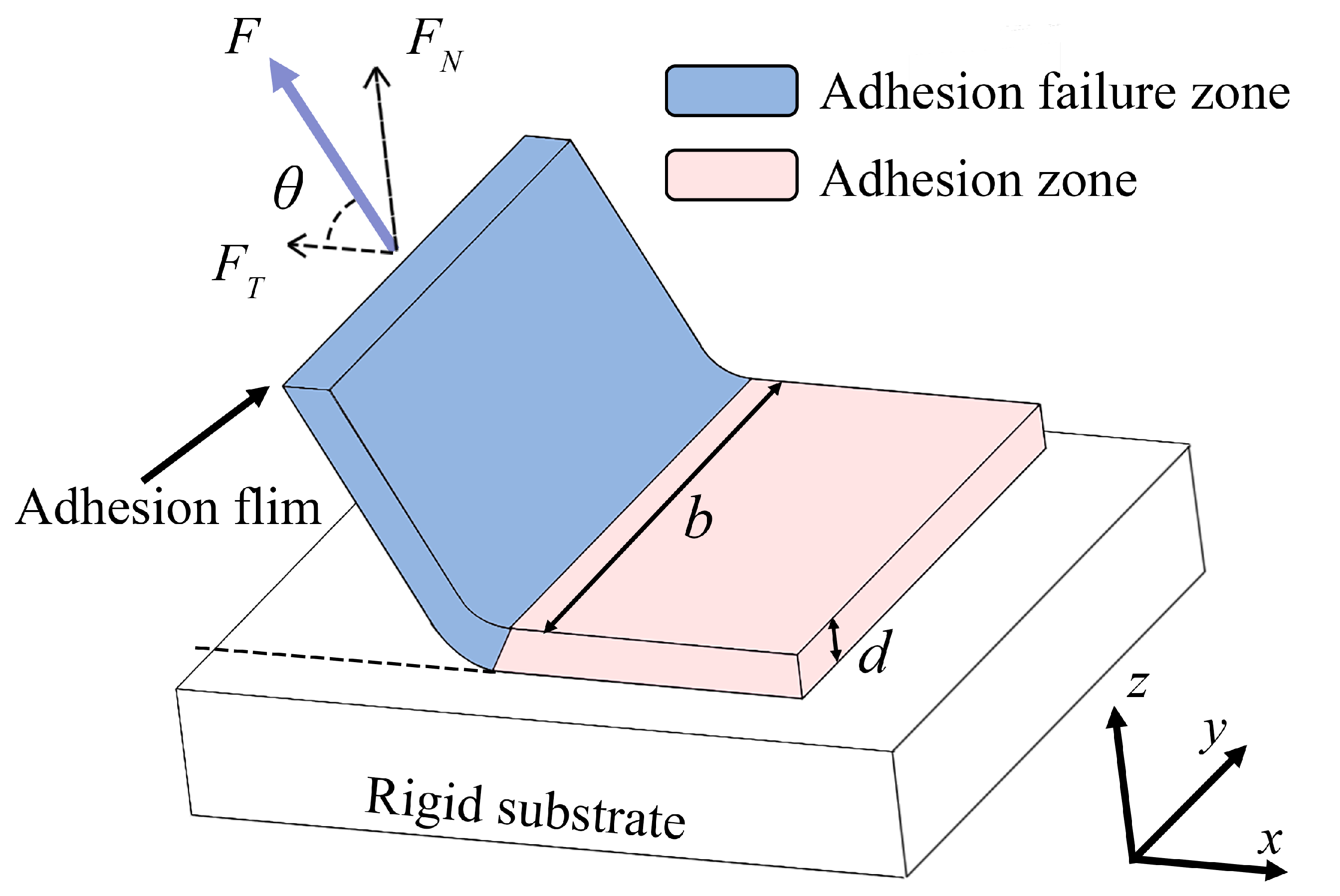
2.1. Mechanism of Detachment Force Regulation

An isotropic adhesive can repeatedly adhere to a surface without leaving a trace and can maintain a certain normal adhesion strength without tangential adhesion strength, which is beneficial for adhesion reliability. However, this can also lead to an instant change in the adhesion force when the adhesion breaks. To reduce the adhesion strength during the detachment of the adhesive, detachment is generally carried out via peeling, where a peeling force in a certain direction is applied to one end of the adhesive. The Kendall model [21], shown in Figure 1 and Equation (1), gives the steady-state relationship among peeling force F, elastic modulus of the adhesive pad E, thickness of the adhesive pad d, width of the adhesive failure area b, peeling angle θ , and peeling energy constant R, which is related to the peeling speed. The influence of peeling speed on adhesion strength has been studied in Reference [23]. The adhesion strength can be regulated mainly via peeling angle θ and R. Because adjusting the peeling speed would prevent rapid peeling, this study regulates adhesion strength by adjusting θ .
F b 2 1 2 d E + F b ( 1 cos θ ) R = 0
because the elastic term is generally small, the normal and tangential adhesion forces F N and F T , respectively, are given by:
F N = b R sin θ 1 cos θ , F T = b R cos θ 1 cos θ ( θ 0 , π ) .
At the detachment end state, the detachment force instantly decreases to 0, which affects the motion state of the robot. Therefore, a smaller adhesion strength of the detachment end state is beneficial for robot motion stability. According to Equation (2), F N and F T are negatively correlated with peeling angle θ . When θ is close to π , F N is close to 0, which is the ideal detachment situation. Therefore, increasing the peeling angle to near π can effectively reduce the probability of instability of the robot during wall climbing. The peel-zone model [20] with friction considered gives a similar conclusion with Kendall model.
In a practical situation, the actual adhesion state (related to R and b) is affected by such factors as the stiffness of the adhesive feet and the size of the adhesion pre-pressure. We conducted experimental verification for this phenomenon. The experiment method and the results are shown in Appendix A.
It is not difficult to find that the above factors both influence the adhesion area. In addition, under the same experimental conditions, the adhesion area will still be slightly different in multiple experiments. So, the attachment process is an unpredictable process for robots, making it difficult to find a desired peeling force or design an optimal foot trajectory online. Therefore, we regulate the peeling angle rather than the unpredictable peeling force.
Most existing wall-climbing robots, such as Stickybot III [13] and AnyClimb [15,16], realize joint motion using position control that tracks a trajectory. With this kind of trajectory tracking control (comparison method in Section 4 and the Supplementary Materials’ Video S1), it is difficult to design an optimal foot trajectory for specific adhesion situations because of the lack of feedback. Because position control can output a large moment, the adhesive sheet at the detachment end state under trajectory tracking control is prone to overall adhesion failure rather than peeling, which leads to uncontrollable adhesion strength. Thus, the traditional trajectory tracking control algorithm is not applicable for wall climbing. This study proposes an online adaptive impedance control where the stiffness and damping are tuned online for adhesive attachment and detachment.
The force exerted by the robot foot is shown in Figure 2a. P j 1 is the current foot position, P j , d is thew expected foot position in the next time step, P j is the actual foot position in the next time step, F a d is the adhesion force, F l i m b is the driving force exerted by the limb of robot, and F r is the resultant force. Under trajectory tracking control, the end of the robot foot moves directly from P j 1 to P j , d , regardless of the magnitude of the detachment force. A joint torque ring can be used to establish proportional-derivative control between P j , d and P j 1 to mitigate this problem. The peeling angle corresponding to P j decreases compared with P j , d obtained by trajectory tracking control.

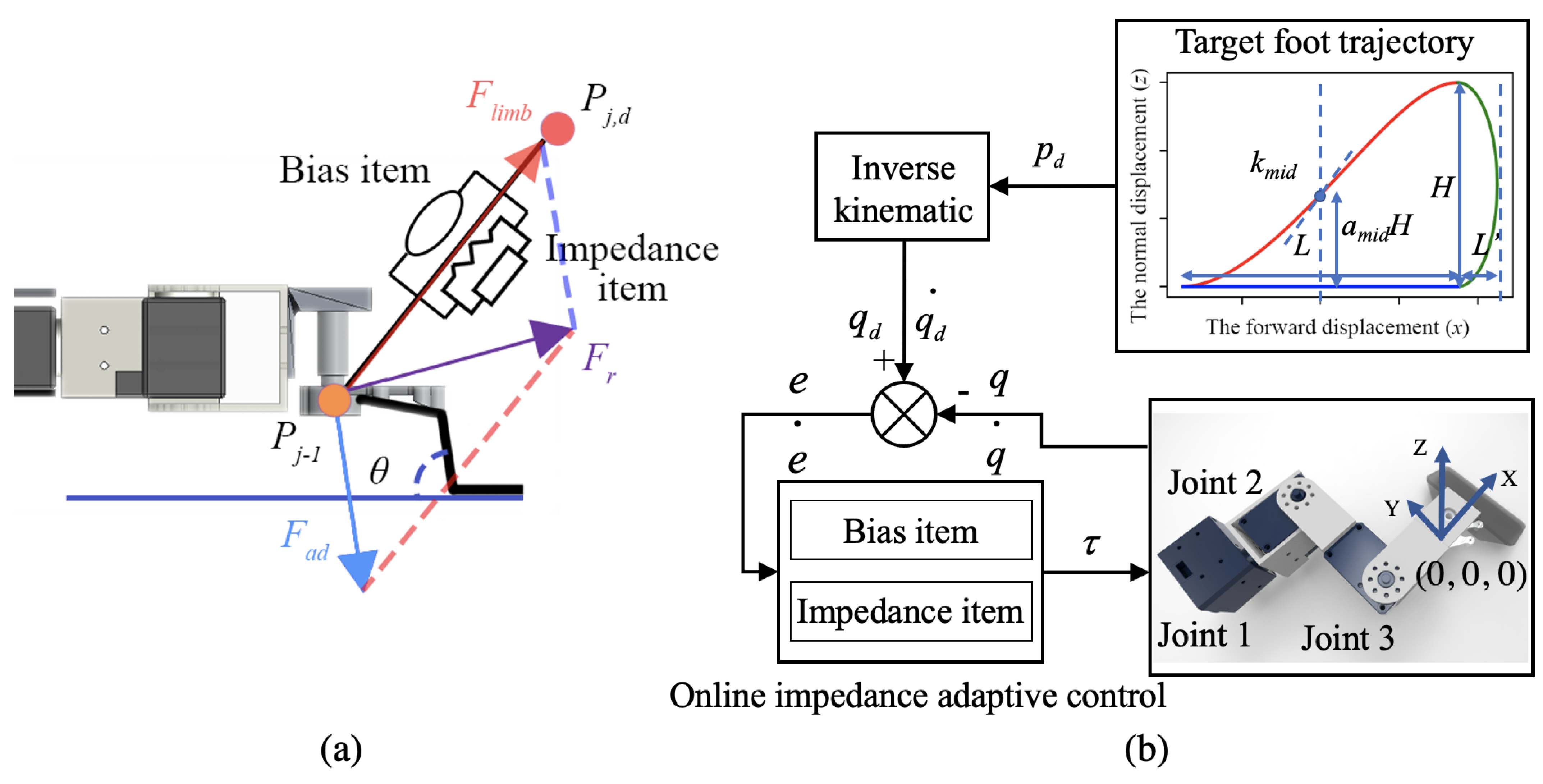
2.2. Online Impedance Adaptation Controller

A simple proportional-derivative control can realize the adjustment of the peeling angle, but it lacks online impedance modulation, leading to a lack of adaptability to the adhesion and non-adhesion states. In addition, due to the lack of a bias term, this control method has poor trajectory tracking performance on non-adhesion state. To address this problem, an online impedance adaptation controller [24] is applied to the variable stiffness control to improve motion stability. The overall control strategy is shown in Figure 2b.
The robot’s target foot trajectory p d ( t ) is shown in Figure 2b. The whole trajectory is divided into three stages, namely detachment (red trajectory), attachment (green trajectory), and stretching (blue trajectory). The foot trajectory of an adhesive wall-climbing robot has been studied in References [13,25]. However, these foot trajectory plannings are both aimed at the anisotropic adhesive materials, and the peeling angle is small in the detachment stage, so they cannot be applied to the isotropic adhesive materials. According to Equation (1), θ directly affects adhesion strength. Thus, peeling angle θ can be initially set to a large value so that the robot can enter the detachment state as soon as possible. In the middle stage, to accelerate detachment, the change rate of the foot on Z direction can be increased to decrease peeling angle θ . There is still a constraint relationship between the climbing surface and the adhesion foot, and, thus, the adhesion force does not change rapidly. In the last stage of detachment, to reduce the influence of the detachment force on robot stability, peeling angle θ is increased.
A semi-elliptic trajectory is a convenient scheme for the attachment stage. It allows the middle section to preload and the last section to stably stretch, making adhesion reliable. This trajectory can be expressed by a trigonometric function in the X and Z directions. The corresponding velocity and acceleration are continuous.
To maintain fuselage stability during climbing, a straight-line function is used in the stretching stage.
The mathematical expressions of the detachment, attachment, and stretching trajectories are, respectively, given by:
z = a m i d H + k m i d x + 4 1 2 a m i d H L 2 x 2 + 2 4 k m i d L + 5 H L 3 x 3 8 1 2 a m i d H L 4 x 4 + 8 2 k m i d L 3 H L 5 x 5 ( x [ L 2 , L 2 ] , y = l 1 ) ,
( x L 2 ) 2 L 2 + ( z H 2 ) 2 H 2 2 = 1 ( x [ L 2 , L 2 + L ] , y = l 1 ) ,
z = 0 ( x [ L 2 , L 2 ] , y = l 1 ) ,
where x , y , z are the three dimensional coordinates of the foot with respect to the base coordinates of the shoulder, L and H are the length and height of a single step, a m i d H and k m i d are the height and slope of the constraint point of detachment trajectory, l 1 is the length of the robot’s thigh, and L is the extra forward distance in semi-elliptic trajectory.
From the designed trajectory, the desired joint angle and angular velocity are obtained via inverse kinematics. To realize impedance adaptation during peeling, an online impedance adaptive controller (OIAC) [24] is used to produce online variable compliant joint motions for adhesive attachment and detachment. This controller has been applied to finger and elbow exoskeletons, leading to stable variable compliant joint motions [26,27]. Taking a 3-DOF limb, for example, the torque of all joints is controlled using the equation:
τ ( t ) = F ( t ) + K ( t ) e ( t ) + D ( t ) e ˙ ( t ) ,
where τ ( t ) R 3 × 1 is the output torque of joint 1–3, F ( t ) R 3 × 1 is the online adjustment bias term, and K ( t ) R 3 × 3 and D ( t ) R 3 × 3 are time-varying impedance parameters adjusted online. The position, velocity, tracking error ( e ( t ) , e ˙ ( t ) , ε ( t ) R 3 × 1 ) are given by:
e ( t ) = q d ( t ) q ( t ) , e ˙ ( t ) = q ˙ d ( t ) q ˙ ( t ) , ε ( t ) = e ( t ) + β e ˙ ( t ) ,
where q ( t ) R 3 × 1 is the current position of the joint, q d ( t ) R 3 × 1 is the target position, and β is the tracking factor in tracking error to adjust the proportion of the damping term. The bias term and impedance parameters are given as follows:
F ( t ) = a 1 ( 1 + b ε ( t ) 2 ) ε ( t ) , K ( t ) = F ( t ) e T ( t ) , D ( t ) = F ( t ) e ˙ T ( t ) ,
where the parameters a , b R 3 × 3 were chosen to perform proper online impedance adaptation, thereby avoiding motor torque saturation. It has been shown that online impedance adaptation control can prevent motor dysfunction, which may result from conventional impedance control [26].
The adaptive law of OIAC over state-of-arts are provided in Appendix B. With OIAC, the robot can converge the direction of the detachment force to the tangential forward. Besides, because all joints have impedance characteristics, the limb joints in the stance phase can absorb an instantaneous impact, thus reducing the influence of various forces, including the detachment instantaneous force, on adhesion in the stance phase.

3. Robot System

The wall-climbing robot used to validate the proposed strategy, IBSS–8, is briefly introduced in this section.

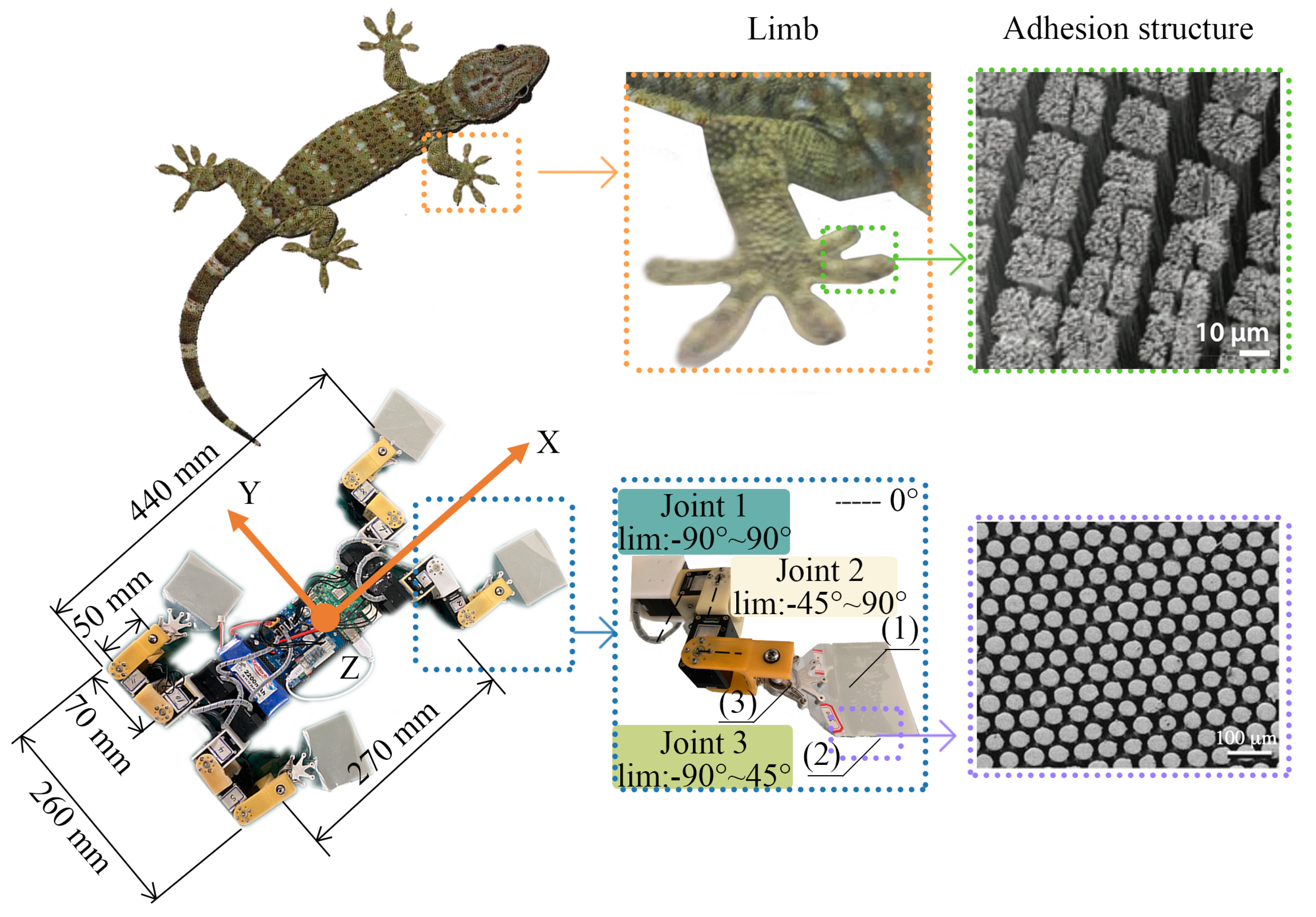
3.1. Mechanical Structure of Wall-Climbing Robot

To emulate the motion performance of a gecko, we designed a gecko-mimetic wall-climbing robot with dry adhesion, called IBSS–8 (dimensions: 440 mm × 260 mm × 45 mm, mass: 1.98 kg with a 2600 mAh 12.1 V battery, center of mass: 18 mm to the robot chassis, battery life: 25 min on full charge), shown in Figure 3, based on the size ratio of a gecko.
A single−limb mechanism, the core unit of robot motion, determines the reliability of adhesion and detachment flexibility. To ensure that the robot can realize flexible three-dimensional single−limb movement without redundant actuation, the single−limb design is based on the gecko limb structure. The hip and the knee active joint are used (the wrist active degree of freedom is not used). This design realizes gecko-like limb movement with flexible switching between attachment and detachment states.
The adhesive unit (see Figure 3) used in the foot is made of polyvinyl siloxane (PVS), which is similar to gecko bristles and can, thus, stably adhere to a smooth surface. The upper surface of the foot is made of polyvinyl chloride (PVC). Foot drive types are important factors affecting the reliability of the detachment, which include active detaching foot, such as stickybot [12], and the passive detaching foot, such as CLASH [14] and Anyclimb [15]. The active detaching foot can make the detachment more reliable, but also need an additional driver to control the toes, which increases the mass of the robot, the passive detaching foot is chosen in robot design. The shape of the sole also greatly affects the adhesion. The common types of the sole include the toe imitating strip foot [14] and the sole-imitating circular foot [15]. The tangential adhesion strength of the strip foot is anisotropic, while the circular foot is isotropic. The circular foot is more suitable for a multi-contact wall-climbing robot because the detachment normal impact may cause adhesion failure. To achieve the smooth detachment of the robot and provide more adhesive force, we expanded the striped foot into a rectangular foot. Combined with a series of parameters, such as the tangent adhesive strength per unit area (2.2 N/cm 2 ) of the adhesive material, the ratio of the actual adhesion area to the foot area (20%), and the mass of the robot, the size of the adhesive foot was determined to be 90 mm × 50 mm. During adhesion contact, the whole foot and the adhesive surface are at a 15° angle, and the PVC surface is forced to bend and deform, thus providing the required pre-pressure for PVS adhesion. The ball bearing on the foot provides a passive degree of freedom for foot posture self-adaptation during the stance phase. The upper part of the foot is connected to a single limb of the robot via a spring to realize the resetting of the soles. PVS provides a reliable adhesion force for robot climbing movement, but the large required detachment force affects the stability of robot climbing.

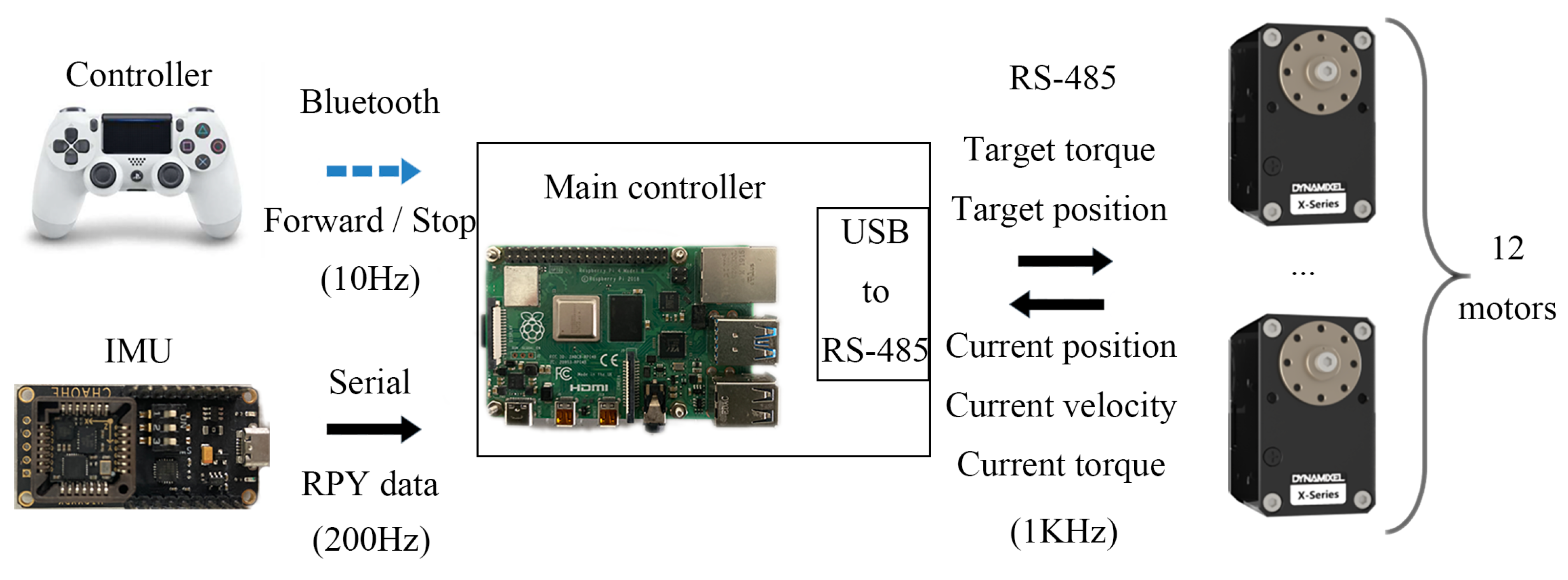
3.2. Control System Setup of Wall-Climbing Robot

An online impedance adaptation controller is proposed to remove the trade-off between PVS attachment strength and ease of detachment. To realize the motion controller, a reproducible control system is adopted in IBSS–8, as shown in Figure 4. The robot’s main controller, a Raspberry Pi 4 Model B, is responsible for motion control, including movement gait planning, joint movement parameter generation, and sensor data acquisition. The main controller communicates with the robot joint motors (Dynamixel XM430-W350), which support position control mode and torque control mode, via RS-485 interface. Depending on the control mode, the target torque or position is sent to the motors, which provide the current position, angular velocity, and torque as feedback. To ensure flexible motion in torque control, the communication frequency is set to 1 kHz (USB transmission limits). This motion control system is stable and efficient in practical operation and meets the requirements of most current control algorithms.
The main controller can receive input information from control peripherals (e.g., handles) via Bluetooth. The communication frequency of this link is 10 Hz to save computing power. Inertial measurement unit data are read through a serial port to obtain robot attitude information. The communication frequency of this link is set to 200 Hz to obtain the robot pose accurately and in real time.
As for the parameter in control method, based on the geometric parameters of the robot’s single leg and adhesion foot, we test the foot trajectories with different lengths and heights and obtain the trajectories of the maximum length of the legs under the condition of stable detachments. Table 2 shows the trajectory parameters selected in this paper.
Equation (9) shows the parameters a , b (see Equation (8)) for joints 1–3 (see Figure 2b). The parameter a of joint 1 is bigger than that of joint 2 and 3, which can make the feet more compliant in the normal direction.
a = 1.6 0 0 0 1.0 0 0 0 1.0 , b = 0.5 0 0 0 0.5 0 0 0 0.5 .

4. Experiments and Results

The evaluation of the online impedance adaptive control in terms of motion stability improvement was conducted using a series of experiments. The detachment force trace of the robot during climbing was obtained to verify whether the online impedance adaptive control (OIAC) can control the adhesion strength of the adhesion comparing to trajectory tracking control (TTC). Then, a robot climbing experiment was carried out on various surfaces with various slope angles. The stability of the robot was characterized by its attitude angle oscillation to verify whether OIAC can effectively improve robot motion stability.

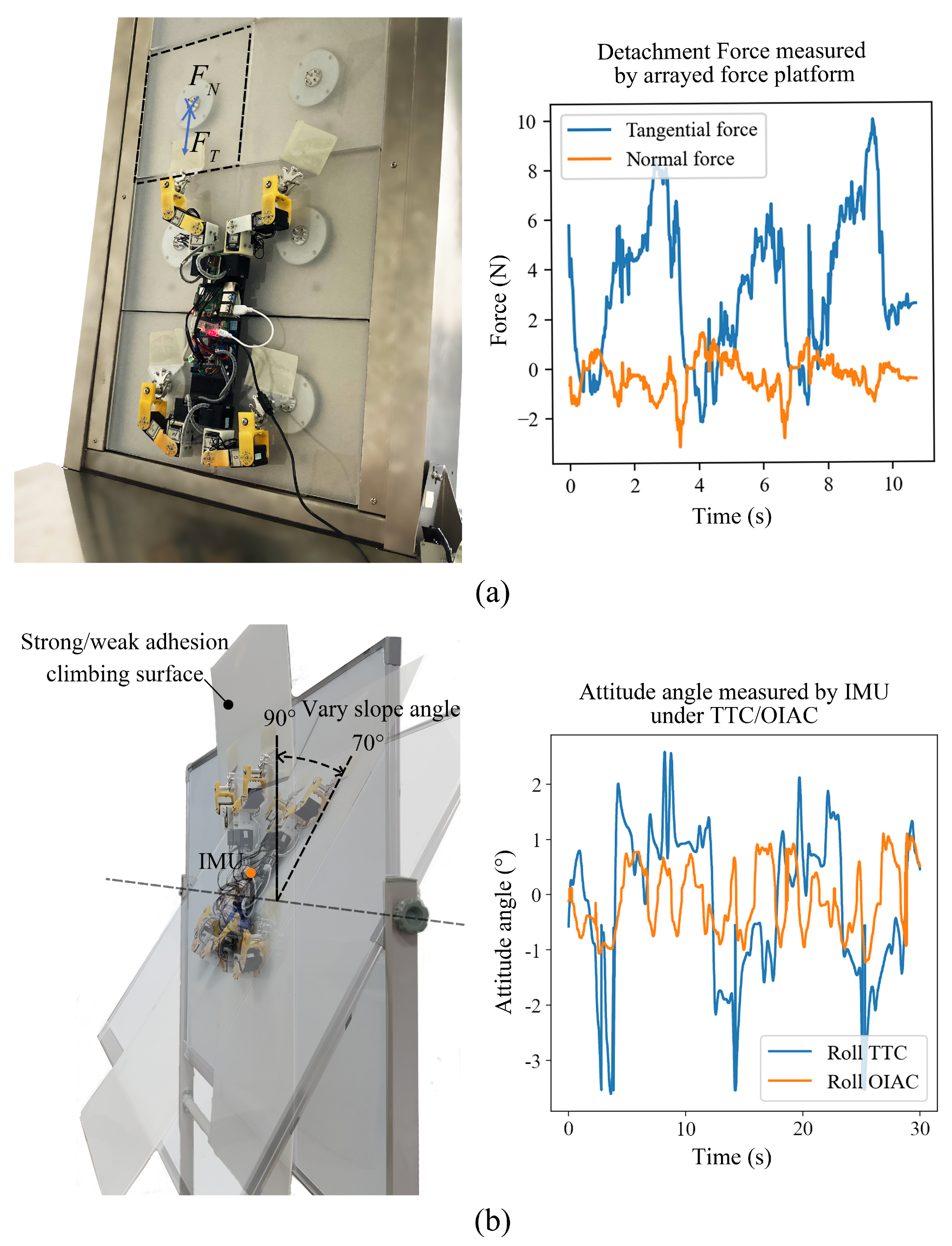
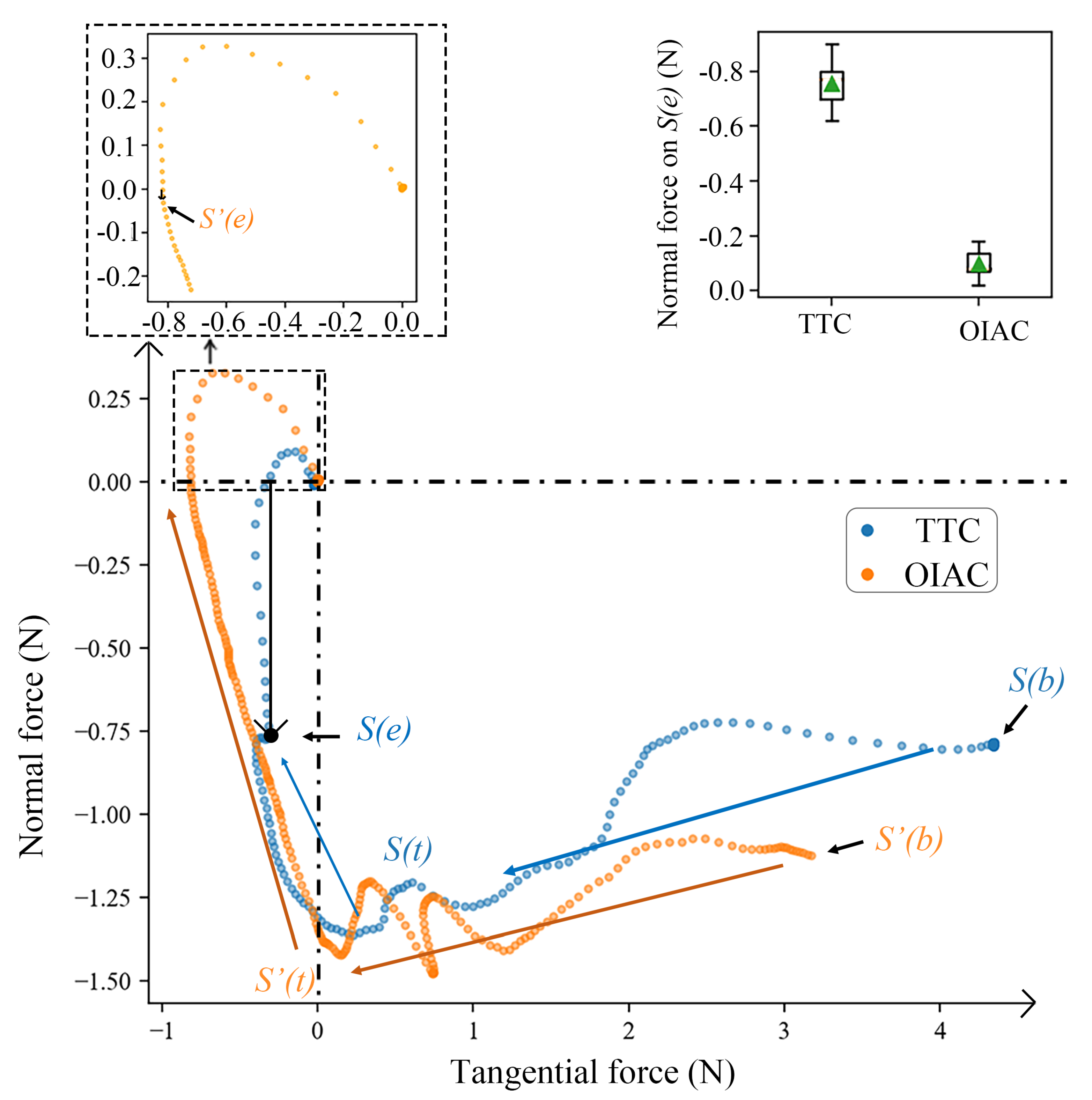
4.1. Detachment Force Trace during Climbing

The detachment force trace can be used to study detachment behavior based on the profiles of the tangential force and the normal force during detachment. Besides, the magnitude of the peeling angle θ can be analyzed, and the variation trend of the adhesive force during peeling can be obtained.
A platform equipped with force sensors, shown in Figure 5a, was used to collect the detachment force trace. Each acrylic plate is a three-dimensional force sensor (precision: +/−0.05 N, frequency: 200 Hz). Each limb was attached to its own force sensors to prevent contamination by other limbs. The slope angle of the test platform was set to 80°. The robot climbed the platform under TTC and OIAC, respectively, and the tangential force and normal force during detachment were recorded. The measured single−limb detachment force trace is shown in Figure 6.
For both TTC and OIAC, in the peeling acceleration stage ( S ( b ) - S ( t ) ), the peeling speed was low; thus, the peel strength was small (see Equation (1)). The peeling angle and speed in this phase increased gradually. In peeling stage ( S ( t ) - S ( e ) ), the peeling speed was at a constant value and the peeling angle increased until complete adhesion failure. The adhesion force then rapidly returned to zero.
The force trace values under the two control methods are quite different, especially the normal force on S ( e ) , which has the greatest influence on robot stability. Based on a statistical analysis of the results of many experiments, under trajectory tracking control, the mean value of normal force on S ( e ) was −0.76 N and the corresponding peeling angle θ was 102.97°; under OIAC, these values were −0.09 N and 174.29°, respectively. These results indicate that the wall-climbing robot with the proposed method exhibits compliant and stable detachment behavior.

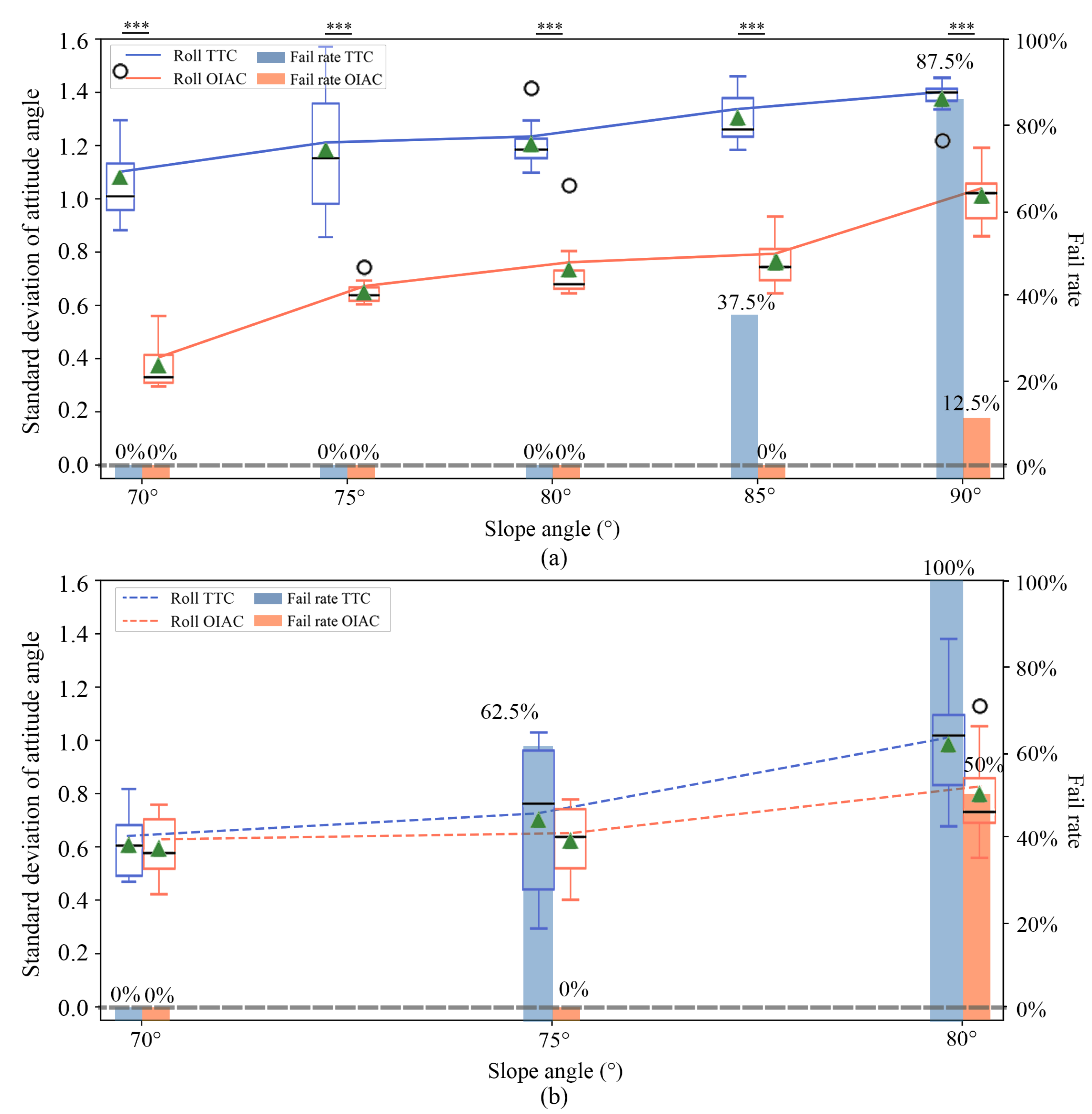
4.2. Robot Stability on Various Surfaces with Various Slope Angles

The most challenging task for a wall-climbing robot is stable operation on a slippery surface with a large slope angle. Motion stability experiments were carried out under these conditions to confirm the ability of OIAC to regulate detachment under different adhesion states.
Teflon is one of the few materials to which geckos cannot stably adhere. PVS, used in this study, produces weak adhesion to a Teflon surface. In this experiment, glass and Teflon were used as climbing substrates with strong and weak adhesion, respectively. The climbing substrates were attached to a platform with an adjustable slope angle, as shown in Figure 5b.
To evaluate the motion stability of the robot, the roll-pitch-yaw ( α - β - γ ) attitude information and the climbing failure rate of IBSS–8 on the glass and Teflon surfaces at various slope angles were recorded several times. The standard deviation of rolling angle α which can best reflect the change of normal force was calculated and used as the quantitative evaluation of the vibrations. The statistical results are shown in Figure 7.
For both surfaces, the support force from the ground decreased and the roll, pitch, and yaw angle oscillation amplitudes increased with increasing slope angle.
From Figure 7, we can see that the rolling angle α oscillation amplitude of IBSS–8 is significantly reduced compared with the TTC method in the process of climbing on the glass surface with different slope angles. In the process of glass surface climbing, the amplitude of rolling angle oscillation under OIAC was significantly different from the amplitude of TTC under different slope angles. Due to the strong adhesive strength of the adhesive material to the glass, the normal force at the detaching end state will directly cause the robot to vibrate at the rolling angle if the peeling process is not regulated. So, comparing the average rolling angle standard deviation when climbing on the glass surface to the value on Teflon surface under the same slope angle, it is not difficult to find that, under the trajectory tracking control, the oscillation amplitude on the glass is greater than the one on the Teflon, and, under our method, the oscillation amplitudes of the two materials are basically the same; this is because, under the help of OIAC, the peeling angle at the detaching end state is close to π , and there is little change in the normal adhesion force. The above data strongly prove that, no matter the size of the adhesion load and the current slope angle, OIAC can effectively regulate the peeling angle and adhesion strength.
During gecko movement, the force increment in the toe detachment process does not change significantly because of the change in the external load, which greatly contributes to movement stability. Under the proposed method, the variation trend of adhesive strength of the robot is similar to that of the gecko.
The success rate of climbing directly confirms the superiority of OIAC. For the glass surface, IBSS–8 started to fail at a slope angle of 85° under TTC and succeeded only once at 90°. Under the proposed method, IBSS–8 failed only once at 90°. For the Teflon surface, IBSS–8 failed completely at a slope angle of 80° under TTC but had a success rate of 50% at this angle under the proposed method. These results confirm that the proposed control method reduces the probability of robot instability during climbing.
Besides, the climbing speed of the robot on the 90-degree glass surface with tripod gait (see Supplementary Materials’ Video S1) is 0.35 cm/s, while that with trot gait is 0.6 cm/s. However, the movement of the robot is unstable under trot gait. The adhesion strength and peeling speed of the sole are the main reasons to limit the speed improvement. Another limitation for the proposed architecture is that it lacks an online trajectory adaptor.

5. Conclusions

The compliant detachment is the key obtained for stable movement of dry-adhesion wall-climbing robots, especially for vary adhesion states. In this study, an online impedance adaptive control algorithm was proposed to remove this trade-off. The control algorithm makes the joints compliant during the peeling process through stable variable compliant joint motion and controls the peeling angle and adhesion strength. This control algorithm does not require additional sensors or mechanical structures and, thus, does not increase the weight of a wall-climbing robot. Controllable adhesion strength is achieved through the characteristics of the motor, which reduces the probability of instability during wall climbing.
The experimental results show that, for various adhesion loads and slope angles, the adhesion strength can be controlled stably under online impedance adaptation control, which removes the trade-off between attachment strength and ease of detachment. This allows compliant detachment under strong adhesion conditions.
Although our method improves the stable movement ability of the wall-climbing robot, it is only the basis for the robot to achieve stable motion. In the near future, we will further optimize the foot structure to enable stable attachment of the robot on the surface of the ceiling and other gravity-reversing surfaces. Online impedance adaptive control will be used in the swing phase, and the distribution of stance phase adhesion force needs to be further studied. With excellent stable movement ability, the wall-climbing robot can be equipped with low weight and low energy consumption of the autonomous navigation system to realize unmanned operation without loss of stability.

Supplementary Materials

The following are available online at https://www.mdpi.com/article/10.3390/app11135860/s1, Video S1: the experimental video of robot motion on vertical glass surface.

Author Contributions

B.W. is responsible for the robot structure designing and code writing, X.X. is responsible for the algorithm designing, J.D. is responsible for the control system scheme designing, Z.W. and Z.D. are responsible for the gecko behavior analysising. All authors have read and agreed to the published version of the manuscript.

Funding

This research was funded by National Key R&D program of China(2019YFB1309600) and the Brødrene Hartmanns Grant (No. A36775, X.X. = Project PI).

Institutional Review Board Statement

Not applicable.

Informed Consent Statement

Not applicable.

Data Availability Statement

The data presented in this study are available on https://github.com/bishopAL/GeRot/tree/master/Experiment_data (accessed on 18 January 2021).

Acknowledgments

The authors would like to thank Poramate Manoonpong for research support, and Adam Przywecki, B.Eng., from Liwen Bianji, Edanz Editing China (www.liwenbianji.cn/ac) (accessed on 28 January 2021), for editing the English text of a draft of this manuscript.

Conflicts of Interest

The authors declare no conflict of interest.

Appendix A

Adhesion area is one of the forms of adhesion state. To show the unpredictability of the adhesion state, we built a test platform for adhesion area of the robot’s single−limb, as shown in Figure A1, to explore the influence of parameters, such as adhesion sheet stiffness and pre-pressure on the actual adhesion area. The robot single−limb was used as the verification mechanism of the platform; meanwhile, LED strips are attached to the edge of surface as light source. When the adhesive foot begins to contact with the surface, the bright spot, as shown in Figure A1, will appear. This bright spot represents the actual adhesion area, and the actual adhesion area will be captured by the camera at the back end.
Figure A1. Adhesion area test platform and adhesion area detection process offline. The adhesion area actual image captured by the camera is uploaded to PC for image processing [28]. The frames containing only markers (non-adhesion) were recorded as f b g , and the frames after adhesion were recorded as f s r c . Through the difference between the two frames (Frame difference), the frame f a d containing only adhesion region was obtained, which was binarized and the total number of pixels of adhesion region in the frame was calculated (Binarization). The actual adhesion area is obtained by the ratio of the number of pixels of the reference object to the actual length.
Applsci 11 05860 g0a1
As the upper surface of the adhesive material to verify the influence of the adhesive stiffness on the adhesion area, 1.5 mm, 2 mm, and 2.5 mm PVC sheets (the adhesive stiffness is affected by the thickness) were selected; the pre-pressing depths of 0 mm, 2 mm, 4 mm, 6 mm, 8 mm (the pre-pressing depth is positively correlated with pre-pressure) were selected as the depth of the foot to continue pressing after contacting the adhesive surface to verify the influence of the adhesive stiffness on the adhesion area. Each experiment was performed several times and the actual adhesion area S a d was statistically analyzed, which was divided by the area of adhesive sheet (45 cm 2 ) to obtain the actual adhesion ratio. The results are shown in Figure A2.
Figure A2. The actual adhesion ratio under different adhesion parameters.
Applsci 11 05860 g0a2

Appendix B

OIAC minimizes mission error and maintains single−limb dynamic stability by:
J ( t ) = J c ( t ) + J p ( t ) ,
where J c ( t ) minimizes bias and impedance item error, and J p ( t ) maintains single−limb dynamic stability. J c is given by:
J c ( t ) = 1 2 t T t vec T ( K ˜ ) Q k 1 vec ( K ˜ ) + vec T ( D ˜ ) Q d 1 vec ( D ˜ ) + F ˜ T Q f 1 F ˜ ,
where Q f , Q k , and Q d are symmetric positive-definite matrices. The derivative of J c is given by:
δ J c = J c ( t ) J c ( t T ) = 1 2 t T t tr K ˜ T ( σ ) Q k 1 K ˜ ( σ ) K ˜ T ( σ T ) Q k 1 K ˜ ( σ T ) + tr D ˜ T ( σ ) Q d 1 D ˜ ( σ ) D ˜ T ( σ T ) Q d 1 D ˜ ( σ T ) + tr F ˜ T ( σ ) Q f 1 F ˜ ( σ ) F ˜ T ( σ T ) Q f 1 F ˜ ( σ T ) d σ = 1 2 t T t δ Φ ˜ T ( σ ) Q 1 δ Φ ˜ ( σ ) d σ t T t γ ( σ ) Φ ˜ T ( σ ) Φ ˜ ( σ ) d σ + t T t ε ( σ ) K ˜ ( σ ) e ( σ ) + ε ( σ ) D ˜ ( σ ) e ˙ ( σ ) + ε ( σ ) F ˜ ( σ ) d σ ,
where tr { · } stands for the trace of a matrix. Φ ˜ ( t ) and Q are given by:
Φ ˜ ( t ) = vec ( K ˜ ( t ) ) T , vec ( D ˜ ( t ) ) T , F ˜ ( t ) T Q = diag I Q k , I Q d , Q f ,
and adaptive parameter γ ( t ) is given by:
γ ( t ) = a 1 ( 1 + b ε ( t ) 2 ) .
Similarly, δ J p and δ J are given by:
δ J p = t T t ε ( σ ) K ˜ ( σ ) e ( σ ) + ε ( σ ) D ˜ ( σ ) e ˙ ( σ ) + ε ( σ ) F ˜ ( σ ) d σ , δ J = 1 2 t T t δ Φ ˜ T ( σ ) Q 1 δ Φ ˜ ( σ ) d σ t T t γ ( σ ) Φ ˜ T ( σ ) Φ ˜ ( σ ) d σ .
To decrease J with time, δ J < 0 is necessary. So, the following formula must be satisfied:
γ ( σ ) > 0 , Φ ˜ T Φ ˜ 0 ,
so the parameter a and b must be positive.

References

  1. Ge, D.; Tang, Y.; Ma, S.; Matsuno, T.; Ren, C. A pressing attachment approach for a wall-climbing robot utilizing passive suction cups. Robotics 2020, 9, 26. [Google Scholar] [CrossRef] [Green Version]
  2. Eto, H.; Asada, H.H. Development of a Wheeled Wall-Climbing Robot with a Shape-Adaptive Magnetic Adhesion Mechanism. In Proceedings of the 2020 IEEE International Conference on Robotics and Automation (ICRA), Paris, France, 31 May–31 August 2020; pp. 9329–9335. [Google Scholar]
  3. Seriani, S.; Scalera, L.; Caruso, M.; Gasparetto, A.; Gallina, P. Upside-Down Robots: Modeling and Experimental Validation of Magnetic-Adhesion Mobile Systems. Robotics 2019, 8, 41. [Google Scholar] [CrossRef] [Green Version]
  4. Liu, J.; Xu, L.; Chen, S.; Xu, H.; Cheng, G.; Xu, J. Development of a Bio-inspired Wall-Climbing Robot Composed of Spine Wheels, Adhesive Belts and Eddy Suction Cup. Robotica 2021, 39, 3–22. [Google Scholar] [CrossRef]
  5. Gorb, S.; Varenberg, M.; Peressadko, A.; Tuma, J. Biomimetic mushroom-shaped fibrillar adhesive microstructure. J. R. Soc. Interface 2007, 4, 271. [Google Scholar] [CrossRef] [Green Version]
  6. Parness, A.; Soto, D.; Esparza, N.; Gravish, N.; Wilkinson, M.; Autumn, K.; Cutkosky, M. A microfabricated wedge-shaped adhesive array displaying gecko-like dynamic adhesion, directionality and long lifetime. J. R. Soc. Interface 2009, 6, 271. [Google Scholar] [CrossRef] [Green Version]
  7. Hawkes, E.W.; Eason, E.V.; Asbeck, A.T.; Cutkosky, M.R. The Gecko’s Toe: Scaling Directional Adhesives for Climbing Applications. IEEE/ASME Trans. Mechatron. 2013, 18, 518–526. [Google Scholar] [CrossRef]
  8. Unver, O.; Sitti, M. Tankbot: A miniature, peeling based climber on rough and smooth surfaces. In Proceedings of the IEEE International Conference on Robotics & Automation, Kobe, Japan, 12–17 May 2009. [Google Scholar]
  9. Daltorio, K.A.; Wei, T.E.; Horchler, A.D.; Southard, L.; Wile, G.D.; Quinn, R.D.; Gorb, S.N.; Ritzmann, R.E. Mini-Whegs TM Climbs Steep Surfaces Using Insect-inspired Attachment Mechanisms. Int. J. Robot. Res. 2009, 28, 285–302. [Google Scholar] [CrossRef]
  10. Murphy, M.P.; Kute, C.; Mengüç, Y.; Sitti, M. Waalbot II: Adhesion Recovery and Improved Performance of a Climbing Robot using Fibrillar Adhesives. Int. J. Robot. Res. 2011, 30, 118–133. [Google Scholar] [CrossRef]
  11. Spenko, M.J.; Haynes, G.C.; Saunders, J.A.; Cutkosky, M.R.; Rizzi, A.A.; Full, R.J.; Koditschek, D.E. Biologically inspired climbing with a hexapedal robot. J. Field Robot. 2008, 25, 223–242. [Google Scholar] [CrossRef] [Green Version]
  12. Kim, S.; Spenko, M.; Trujillo, S.; Heyneman, B.; Santos, D.; Cutkosky, M.R. Smooth Vertical Surface Climbing With Directional Adhesion. IEEE Trans. Robot. 2008, 24, 65–74. [Google Scholar]
  13. Hawkes, E.W.; Ulmen, J.; Esparza, N.; Cutkosky, M.R. Scaling walls: Applying dry adhesives to the real world. In Proceedings of the 2011 IEEE/RSJ International Conference on Intelligent Robots and Systems, San Francisco, CA, USA, 25–30 September 2011; pp. 5100–5106. [Google Scholar]
  14. Birkmeyer, P.; Gillies, A.G.; Fearing, R.S. Dynamic climbing of near-vertical smooth surfaces. In Proceedings of the 2012 IEEE/RSJ International Conference on Intelligent Robots and Systems, Vilamoura-Algarve, Portugal, 7–12 October 2012; pp. 286–292. [Google Scholar]
  15. Liu, Y.; Kim, H.; Seo, T. AnyClimb: A New Wall-Climbing Robotic Platform for Various Curvatures. IEEE-Asme Trans. Mechatron. 2016, 21, 1812–1821. [Google Scholar] [CrossRef]
  16. Liu, Y.; Seo, T.W. AnyClimb-II: Dry-adhesive linkage-type climbing robot for uneven vertical surfaces. Mech. Mach. Theory 2018, 124, 197–210. [Google Scholar] [CrossRef]
  17. Hawkes, E.W.; Hao, J.; Cutkosky, M.R. Three-dimensional dynamic surface grasping with dry adhesion. Int. J. Robot. Res. 2016, 35, 943–958. [Google Scholar] [CrossRef]
  18. Autumn, K.; Dittmore, A.; Santos, D.; Spenko, M.; Cutkosky, M.R. Frictional adhesion: A new angle on gecko attachment. J. Exp. Biol. 2006, 209, 3569–3579. [Google Scholar] [CrossRef] [PubMed] [Green Version]
  19. Shui, L.; Jia, L.; Li, H.; Guo, J.; Chen, X. Rapid and continuous regulating adhesion strength by mechanical micro-vibration. Nat. Commun. 2020, 11, 1583. [Google Scholar] [CrossRef] [PubMed]
  20. Pesika, N.S.; Yu, T.; Zhao, B.; Rosenberg, K.; Zeng, H.; Mcguiggan, P.; Autumn, K.; Israelachvili, J.N. Peel-Zone Model of Tape Peeling Based on the Gecko Adhesive System. J. Adhes. 2007, 83, 383–401. [Google Scholar] [CrossRef] [Green Version]
  21. Kendall, K. Thin-film peeling-the elastic term. J. Phys. D Appl. Phys. 1975, 8, 1449. [Google Scholar] [CrossRef]
  22. Tiwari, A.; Dorogin, L.; Bennett, A.I.; Schulze, K.D.; Sawyer, W.G.; Tahir, M.; Heinrich, G.; Persson, B.N.J. The effect of surface roughness and viscoelasticity on rubber adhesion. Soft Matter 2017, 13, 3602–3621. [Google Scholar] [CrossRef]
  23. Villey, R.; Creton, C.; Cortet, P.P.; Dalbe, M.J.; Ciccotti, M. Rate-dependent elastic hysteresis during the peeling of Pressure Sensitive Adhesives. Soft Matter 2015, 11, 3480–3491. [Google Scholar] [CrossRef] [PubMed] [Green Version]
  24. Xiong, X.; Manoonpong, P. Adaptive Motor Control for Human-like Spatial-temporal Adaptation. In Proceedings of the 2018 IEEE International Conference on Robotics and Biomimetics (ROBIO), Kuala Lumpur, Malaysia, 12–15 December 2018; pp. 2107–2112. [Google Scholar]
  25. Wang, Z.; Dai, Z.; Yu, Z.; Shen, D. Optimal attaching and detaching trajectory for bio-inspired climbing robot using dry adhesive. In Proceedings of the 2014 IEEE/ASME International Conference on Advanced Intelligent Mechatronics, Besacon, France, 8–11 July 2014; pp. 990–993. [Google Scholar]
  26. Xiong, X.; Manoonpong, P. Online adaptive resistance control of an arm exercise exoskeleton. In Proceedings of the 23rd International Conference on Climbing and Walking Robots and the Support Technologies for Mobile Machines, CLAWAR, Moscow, Russian, 24–26 August 2020; pp. 31–38. [Google Scholar]
  27. Xiong, X.; Manoonpong, P. Resistance-as-needed (RAN) control for a wearable and soft hand exoskeleton. Gait Posture 2020, 81, 398–399. [Google Scholar] [CrossRef]
  28. Gagliano, S.; Stella, G.; Bucolo, M. Real-time detection of slug velocity in microchannels. Micromachines 2020, 11, 241. [Google Scholar] [CrossRef] [PubMed] [Green Version]
Figure 1. Adhesion film peeling force analysis.
Applsci 11 05860 g001
Figure 2. (a) Force analysis on the foot, the peeling is driven by F a d and F l i m b . (b) Motion control strategy diagram. Taking a 3-DOF limb, for example: The expected foot end coordinate of the single limb p d is given by the trajectory. The expected angle q d and angular velocity q d ˙ of the joints are obtained through the inverse kinematic of the single limb, and the feedback of the current angle q and angular velocity q ˙ is obtained. The error e is input to online impedance adaptive controller, and the joints torque are output to control the single limb. The origin position (the angles of joints 1–3 are set to 0) of the foot end is set as the coordinate original point (0, 0, 0).
Applsci 11 05860 g002
Figure 3. Bionic structure design of IBSS–8 for the body, limb, and adhesion unit. The workspace limitation and 0° position of each joint can be checked. A gecko’s adhesion unit is the bristles of the sole, and that of the robot is PVS [5]. (1) Upper surface of adhesive (PVC). (2) Gecko-like adhesive material (PVS). (3) Passive ball bearing and reset spring.
Applsci 11 05860 g003
Figure 4. Hardware framework of wall-climbing robot control.
Applsci 11 05860 g004
Figure 5. (a) Force-time data of one motion period measured by force platform ( F T represents tangential force, F N represents normal force). (b) IBSS–8 with trajectory tracking control (TTC) and online impedance adaptive control (OIAC), respectively, climbed the platform and the attitude angle was recorded.
Applsci 11 05860 g005
Figure 6. Single−limb detachment force trace and statistical results S ( b ) and S ( b ) : beginning state of detachment under TTC and OIAC, S ( t ) and S ( t ) : turnning state of detachment under TTC and OIAC, S ( e ) and S ( e ) : end state of detachment under TTC and OIAC). The box chart shows the statistical analysis of normal force on S ( e ) and S ( e ) . The green triangles represent the average position.
Applsci 11 05860 g006
Figure 7. Statistical results of robot rolling angle α and the fail rate for various surfaces with various slope angles. Statistical results for (a) glass and (b) Teflon surfaces. In the box chart, the black lines represent the median position and the green triangles represent the average position. In the statistics, *** indicates a significant difference. The P value between roll under TTC and roll under OIAC on glass is 3.43 × 10 5 for 70°, 4.26 × 10 4 for 75°, 1.1 × 10 5 for 80°, 6.84 × 10 7 for 85°, and 2.82 × 10 5 for 90°.
Applsci 11 05860 g007
Table 1. Adhesion and motion controller of the existing wall-climbing robots.
Applsci 11 05860 i001[1] Applsci 11 05860 i002[2] Applsci 11 05860 i003[4] Applsci 11 05860 i004[13] Applsci 11 05860 i005 Proposed Robot
Suction
Magnetic
Claw
Dry adhesion
Position controller
Online impedance
adaptive controller
Table 2. The parameters for adhesion foot trajectory.
LH L a mid k mid
70 mm60 mm10 mm0.451.2
Publisher’s Note: MDPI stays neutral with regard to jurisdictional claims in published maps and institutional affiliations.

