1. Introduction
Touch sensation occurs with the deformation of the skin under external forces and subsequent stimulation of the mechanoreceptors within the tissue. In the human hand, the fingertips exhibit the highest tactile sensitivity as they are densely innervated with sensory neurons [
1,
2]. Hence, the deformation mechanics of the fingertips has received considerable attention in scientific efforts to understand touch sensation [
3,
4,
5] as well as in the design of interfaces that provide haptic feedback [
6,
7,
8].
The perception of dynamic forces applied on the fingertip significantly differs from sensation under static conditions. Human skin is sensitive to vibrations up to 1000 Hz, with the peak sensitivity observed around 250 Hz [
9]. Many researchers have shown that the mechanical properties of the skin play an important role in its frequency-dependent sensitivity. In the case of fingertips, their intricate geometry and multi-layered internal anatomy restrict the accuracy with which analytical methods can predict deformations under dynamic excitation. Hence, many studies have utilized computational simulations to analyze the dynamic deformation mechanics of the human finger.
For instance, Wu et al. [
10] performed two-dimensional (2D) finite element (FE) analyses to simulate the mechanical response of the human fingertip periodically pressing onto flat surfaces. Their results endorsed the suitability of FE simulations in analyzing finger deformation mechanics since their predictions on contact force histories and fingertip–surface separation periods agreed well with the reported experimental observations. Similarly, Wu et al. [
11] examined the dynamic strains in a 2D finite element model of the fingertip section exposed to harmonic line indentation. Their results matched well with known experimental findings: they showed that excitation frequencies ranging from 63 to 250 Hz produce large dynamic strains in the deep finger tissue that accommodates the high-frequency mechanoreceptors, while frequencies lower than 31.5 Hz cause high strain values within the shallow layers that harbor the low-frequency mechanoreceptors. Later, Shao et al. [
12] measured the propagation of cutaneous vibrations in the hand during interactions with different objects. That study demonstrated that the spatial–temporal pattern of vibrations varies systematically across touch interactions, indicating the possibility of decoding the type of interaction from the recorded vibration data. Recently, Panchal et al. [
13] obtained natural frequencies and mode shapes for a simple FE model in the form of a layered rectangular prism, which represents a slab cut out of the skin. The results of that work show that changes in skin elasticity can notably influence the resonance patterns and corresponding frequencies.
The deformation of continuum bodies under dynamic loads is directly influenced by the object’s natural frequencies and mode shapes. However, these modal features have remained unexplored for the fingertip, despite the high interest in the dynamic analysis of human tissue. To address this gap, we developed DigiTip, a detailed 3D finite element model of the human fingertip based carefully on prior studies of fingertip anatomy and biomechanics. We used our model first to determine the fingertip’s natural modes with associated frequencies up to about 250 Hz. Seven modes were identified for the developed model, with several occurring near the frequency of peak sensitivity. Then, we performed frequency-response analyses to predict the forced vibration responses when distributed harmonic forces were applied at the fingerprint centroid in three principal directions. These analyses show that certain free vibration modes are excited significantly more efficiently than the others for the analyzed load cases. The results offer insights into the probable dynamic behavior of the fingertip in haptic applications involving artificial vibratory feedback or light sliding contact with undulating surfaces. They also demonstrate the convenience of utilizing modal information to predict the forced vibration responses of the skin.
2. Discretized 3D Fingertip Model: DigiTip
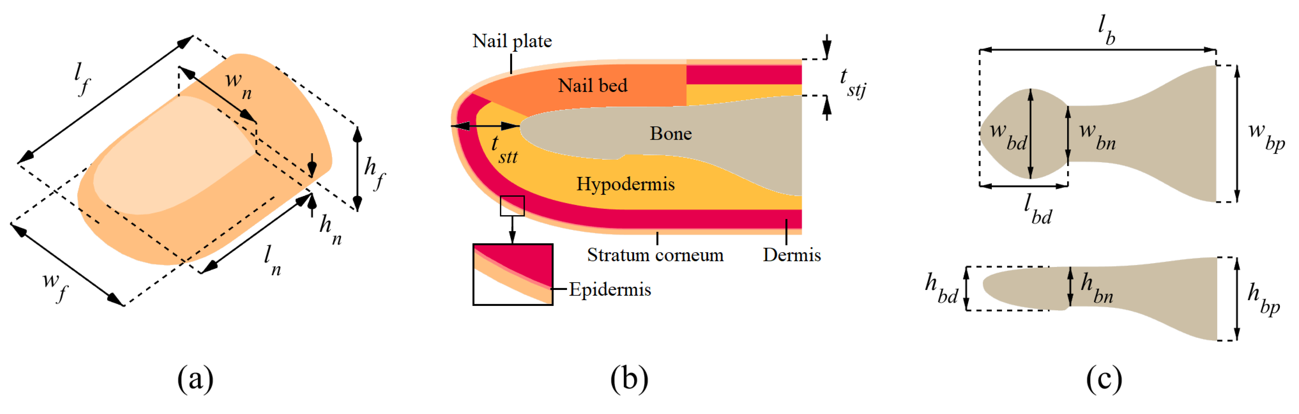
We built a 3D finite element model consisting of six layers: stratum corneum, epidermis, dermis, hypodermis, nail bed, and nail plate. We named this comprehensive model DigiTip since it is a computational model of the tip of a human digit, which is the anatomical designation for a finger or toe.
Figure 1 illustrates the model variables that govern the exterior fingertip dimensions, the thicknesses of the tissue layers, and the dimensions of the distal phalanx. We modeled the surfaces of the finger exterior and bone separately. The upper and lower parts of the front exterior surface were modeled as quarter ellipsoids, which are slightly deflated inward and inflated outward, respectively. This approach resulted in a more realistic fingertip shape. The rear exterior surface was modeled by extruding the front outer surface profile at the fingernail root. The necking of the distal phalanx in the middle section of the bone was included in the modeling. After obtaining the surface profiles for the exterior boundary and bone, we filled the space between the interior soft-tissue layers by preserving their specified thicknesses. The hypodermis has a varying thickness throughout the domain since it is the last soft layer lying over the bone with a variable cross-section.
Table 1 shows the value selected for each DigiTip dimension depicted in
Figure 1; the referenced sources are given in parentheses. When possible, the dimensions were taken for the average adult male index finger, as this case is prevalently reported in the literature. The material properties (elastic modulus, Poisson’s ratio, and density) of the fingertip tissue layers are given in
Table 2. Since we investigate the bulk dynamic behavior of the finger, we did not model the fingerprint ridges, as capturing their surface details would require a vastly increased number of finite elements but would not significantly affect the results of the modal analysis.
We performed the FE analyses using our in-house software developed in MATLAB. The integrated parametric model generator allows the geometric dimensions and mesh density of DigiTip to be easily modified. The generated models consist of solid finite elements whose nodes each have three degrees of freedom, which are the displacements in the
x,
y, and
z directions. Specifically, we employed eight-node hexahedral elements formulated with linear elasticity [
29]. For reference, this 3D FE analysis code was used together with experiments in a previous study by the authors [
30]. The portions of the code related to dynamic analysis were also previously used to compute the free and forced vibrations of shells [
31].
The bone was not explicitly modeled since it was assumed to be rigid due to its significantly higher elastic modulus compared to the other tissue layers [
32]. We numerically imposed this condition by immobilizing the innermost nodes of the hypodermis along the bone’s surface. To allow for tissue deformation, we applied a free boundary condition along the surface where the fingertip would connect with the rest of the finger, and we compared the resulting behavior with the effects of fixing this boundary. Therefore, if we denote the number of nodes within the entire model and on the fixed boundary as
and
, respectively, the system has
total degrees of freedom.
Due to the linear elastic formulation, the developed FE model produces accurate results only for small deformations. We handled this limitation by choosing relatively low excitation magnitudes in the forced vibration analyses (see
Section 5.1).
3. Dynamic Analysis Formulations
3.1. Free Vibration Analysis
This section briefly explains the mathematical basis of free vibration (modal) analysis. In the absence of external forces, the equation of motion for the model can be written as
where
K and
M are the system’s
-by-
global stiffness and mass matrices, respectively. Assuming a complex harmonic displacement solution
, where
is the imaginary unit number, we obtain an eigenvalue equation:
The
are the natural frequencies (in radians per second) that can be obtained by solving det
, which provides nontrivial solutions to the eigenvalue equation. The
are the nodal mode shape vectors corresponding to the
[
33]. These vectors have arbitrary amplitudes and show only the relative displacements of the nodes for each mode, not the absolute displacements that would be expected to occur, as those depend on excitation.
3.2. Forced Vibration Analysis
The steady-state vibration response of the fingertip under external dynamic forces can be computed through frequency-response analysis. In this case, the equations of motion have a nodal force term
f on the right-hand side:
In addition to the stiffness and mass properties, damping can also be incorporated into the system through the complex stiffness matrix
, which is obtained by modifying the stiffness matrix
K with a loss factor
:
[
33]. For a harmonic nodal force vector
with complex amplitude
and frequency
, we can write the steady-state displacement response vector as
. By inserting these terms into Equation (
3), we obtain the following equation, which allows us to solve for the complex displacement amplitude
that results from a particular dynamic force:
The value of the loss factor (
) was determined according to the experimental results given in the literature. When the fingerprint centroid is subjected to harmonic normal indentation with a cylindrical probe of 2 mm radius, the complex part of the effective finger elastic modulus was reported to be 10 times smaller than its real part [
34], which corresponds to a loss factor of 0.1. This value is also consistent with the loss factor calculated using experimentally measured effective fingertip mass (
m), stiffness (
k), and damping (
c) for tangential deformation. Solving the equation
[
33] for the values reported by [
35] yields an average loss factor of 0.11, which is close to 0.1.
4. Modal Analysis
4.1. Convergence Study
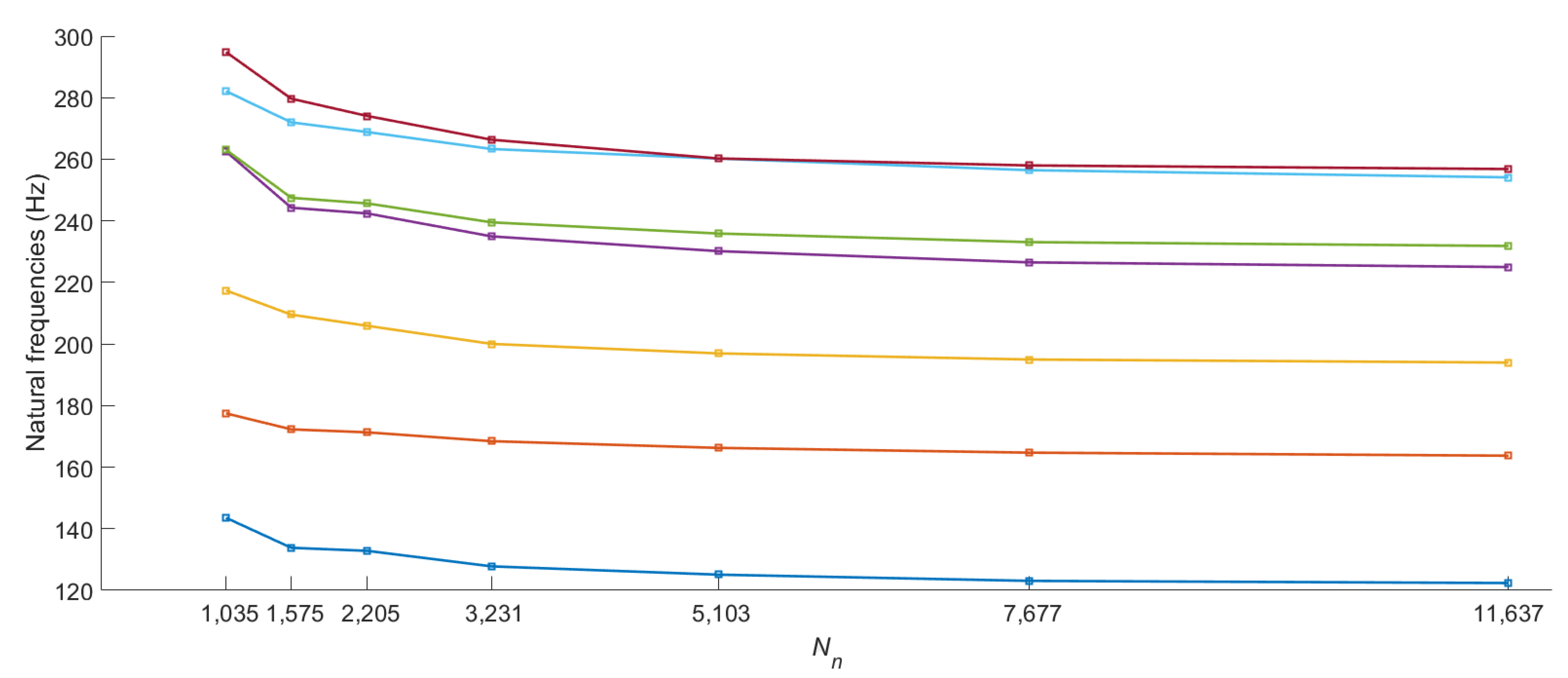
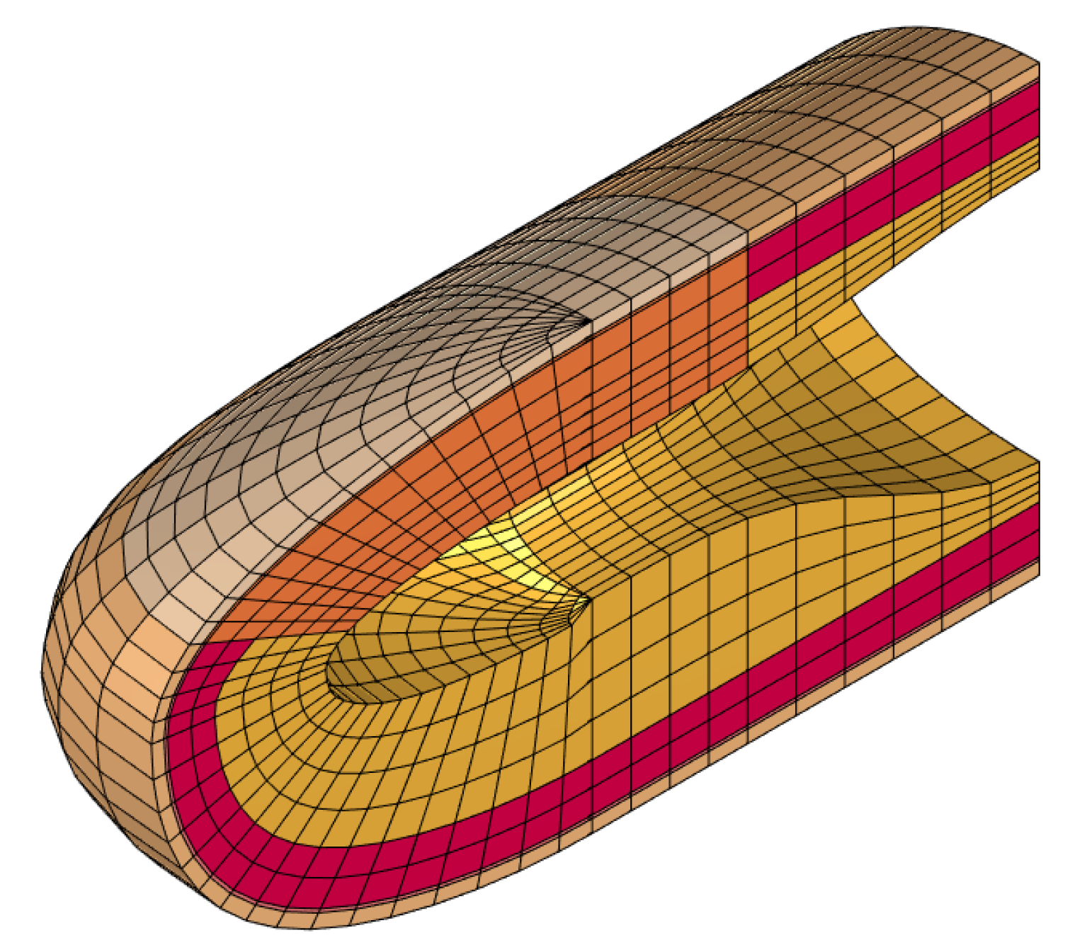
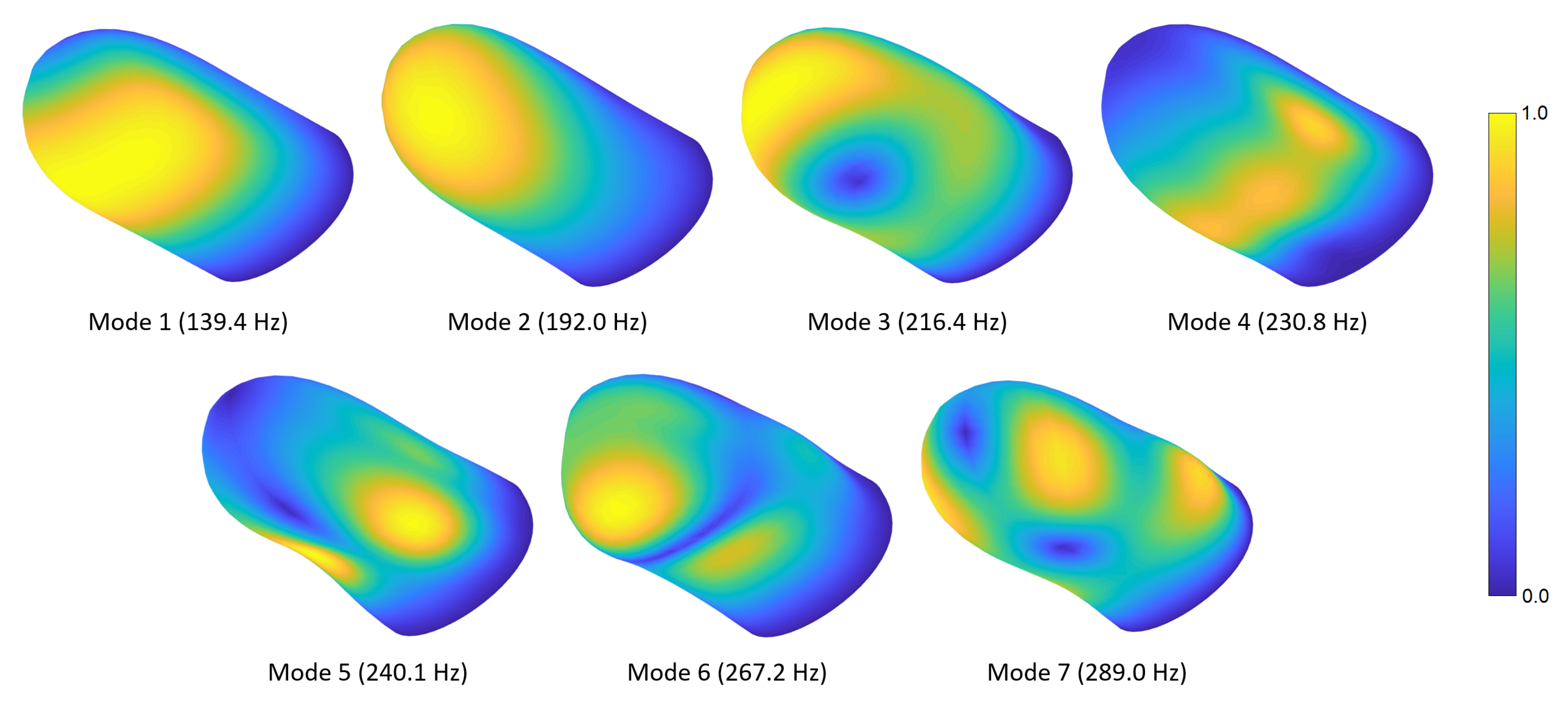
We initially performed a convergence study to determine the minimal mesh resolution required to reach a precise solution. In this analysis, the number of nodes was exponentially increased (by a factor of approximately 1.5 at each step) until the natural frequencies of the relevant vibration modes changed by less than compared to the previous values. For the converged mesh, there are seven modes whose frequencies are below or around 250 Hz. The converged frequency of the eighth mode was computed to be 295.1 Hz, which is relatively distant from the seventh natural frequency of 256.8 Hz. Thus, we considered only the first seven modes in the convergence analysis.
Figure 2 shows the convergence of the first seven fingertip natural frequencies to their final values as we increased the number of nodes in the model. By examining these results, we selected a model with 11,637 nodes and 10,080 elements (see
Figure 3), which satisfies our target tolerance. The volume of the deformable parts of the finger model is 4084.8
; hence, the discretization resolution was approximately 2.47 elements per
, for an average element volume of about 0.405
. There are 1293 nodes on the fixed hypodermis–bone boundary; therefore, the system’s total number of degrees of freedom becomes
when the rear boundary is free. When the other 512 nodes on the rear boundary are also fixed, we have instead
.
4.2. Low-Order Free Vibration Modes
In this section, we present the mode shapes for the natural frequencies computed in
Section 4.1.
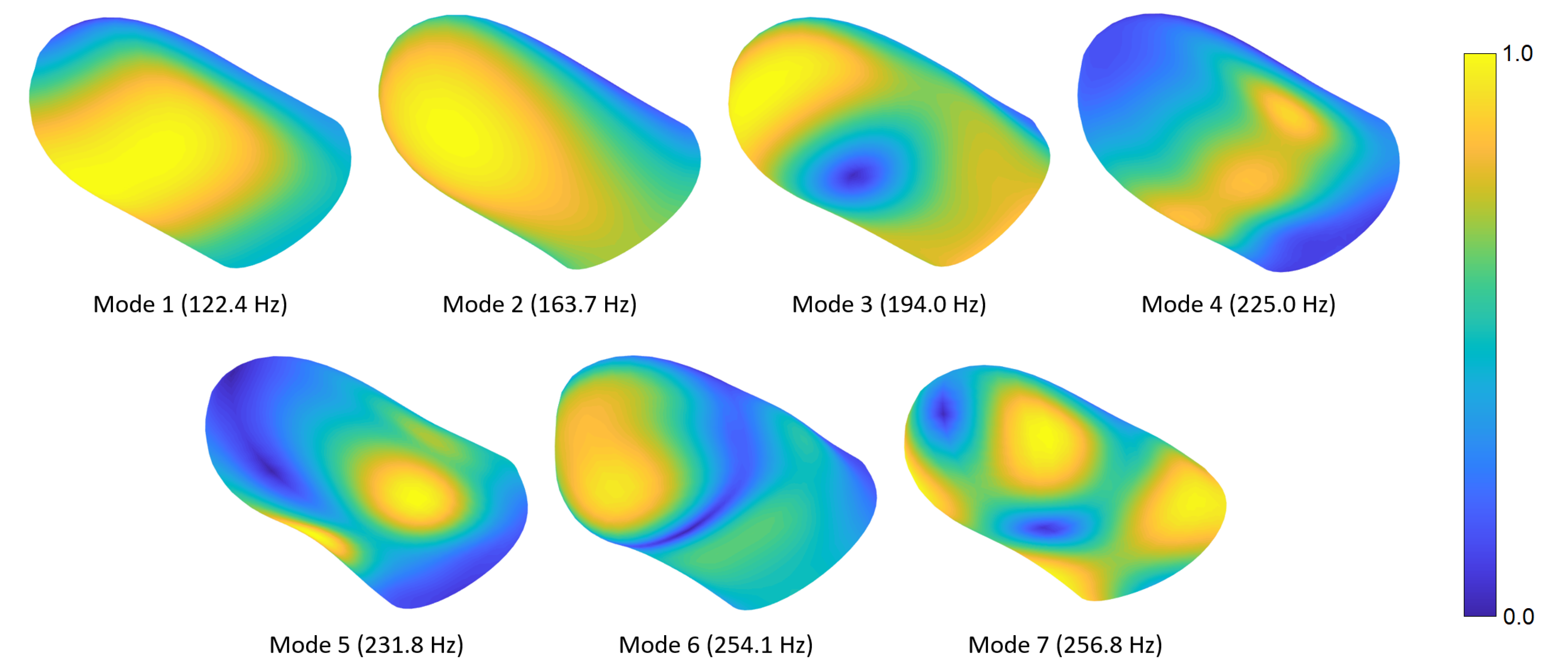
Figure 4 shows the first seven fingertip mode shapes and corresponding natural frequencies. The mesh contours demonstrate relative displacement magnitudes; the blue and yellow colors show the lowest and highest displacement regions, respectively. Readers can refer to
Video S1 provided in the supplementary materials to see the evolution of the modal deformations over time. The first mode primarily exhibits torsional deformation around the distal phalanx. The second mode shape involves a rotational motion around the lateral axis. In the third mode, a lateral movement is observed around the distal section, while some torsional deformation appears at the proximal side. The fourth mode shape includes contraction around the fingerprint centroid and expansion at the sides or vice versa. In the fifth mode, an out-of-phase motion normal to the surface is observed in the lower-left and -right regions of the finger. The sixth mode shape contains out-of-phase vertical motions around the distal and proximal sections. In the seventh mode, distal-left and proximal-right sides contract toward the fingerprint centroid, while distal-right and proximal-left sections expand outward, or vice versa.
As described before, the rear boundary of the modeled fingertip is free to move except the innermost nodes, which are fixed as they are in contact with the bone. We explored the implications of this modeling decision by performing additional modal analyses for the other extreme condition, in which the rear boundary is entirely restrained.
Figure A1 in
Appendix A shows the results, which can be compared with
Figure 4. This investigation shows that immobilizing the nodes at the proximal boundary of DigiTip causes the modal frequencies to rise, but the general shapes and the order of the modes do not change. This boundary condition has a limited influence on the modal dynamics since the bone’s cross-section expands toward the joint and decreases the soft-tissue thickness. The observed insensitivity also supports the simplification of further anatomical details (e.g., tendons) around the interphalangeal joint. However, one should note that a real finger joint might exhibit additional damping mechanisms.
The influence of the presented natural vibration modes depends on the application of interest. For example, the modes that involve normal motion at the skin surface (e.g., the fifth and sixth modes) probably play an essential role in scenarios that provide normal excitation, such as the ultrasonic cues provided during mid-air haptics. The modes that exhibit tangential skin motion are likely to have a major impact in situations where the finger is exposed to lateral vibrations of a contacted object. The first and second modes may be particularly important since the bulk in-phase motion of the skin can cause significant resonances. However, the modal attributes may vary due to prestressing effects, which depend on the magnitude of the pressing force.
5. Frequency-Response Analysis
5.1. Loading
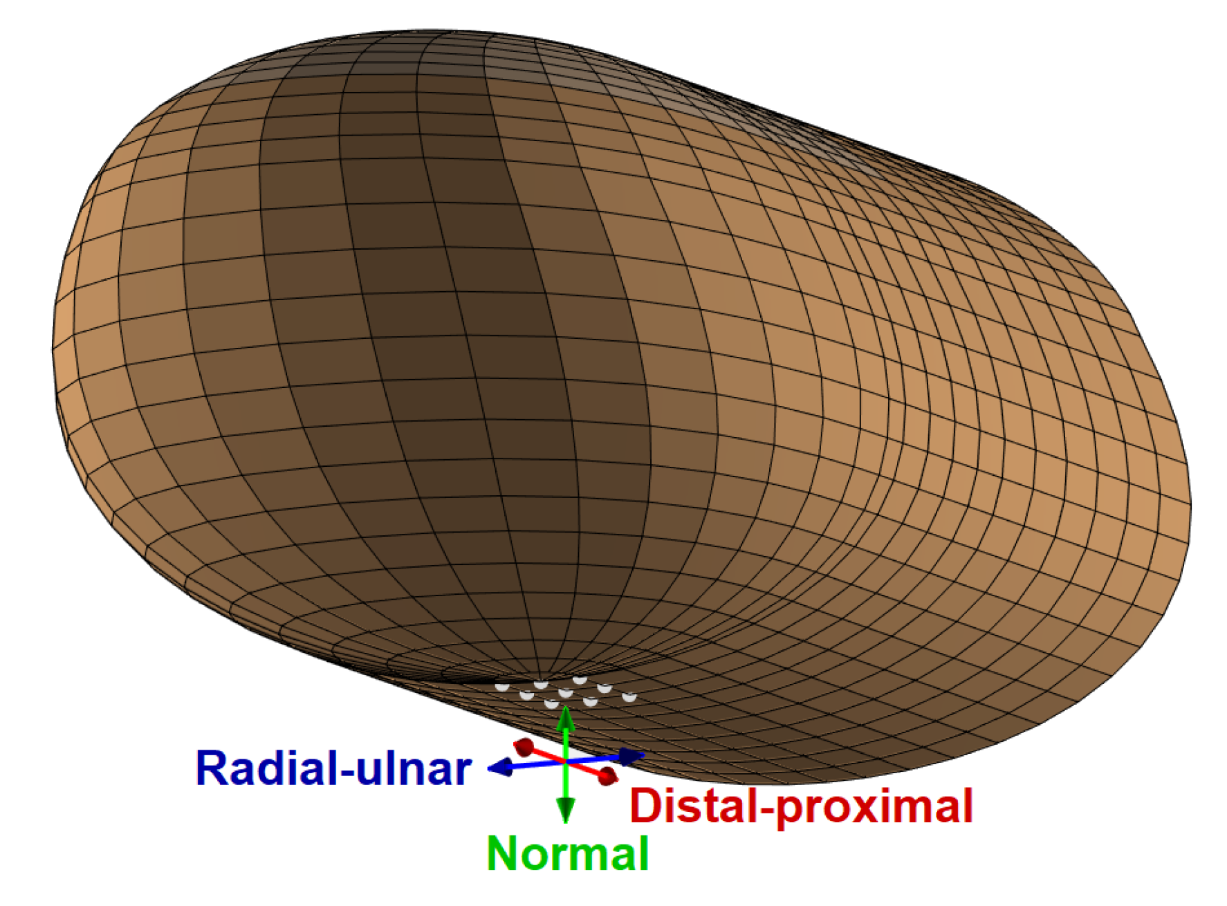
We applied harmonic forces in the region of the fingerprint centroid in three orthogonal directions: normal, radial–ulnar, and distal–proximal, which are shown in
Figure 5. The dynamic force was equally distributed to nine neighboring points selected by considering the nodes of the discretized model in the center of the finger pad, which is a common location for haptic stimulation [
36]. The excitation nodes lay in an approximately rectangular region with edge lengths of 1.92 mm in the radial–ulnar direction and 2.45 mm in the distal–proximal direction, covering an area of about 4.7
. This size is between the tip areas of the cylindrical indenters with 1 and 2 mm radii used in [
34], which is the study that we used to estimate finger pad damping properties (see
Section 3.2). We chose a total force amplitude of 0.1 N assuming a light-touch scenario [
12].
5.2. Displacement FRF Curves
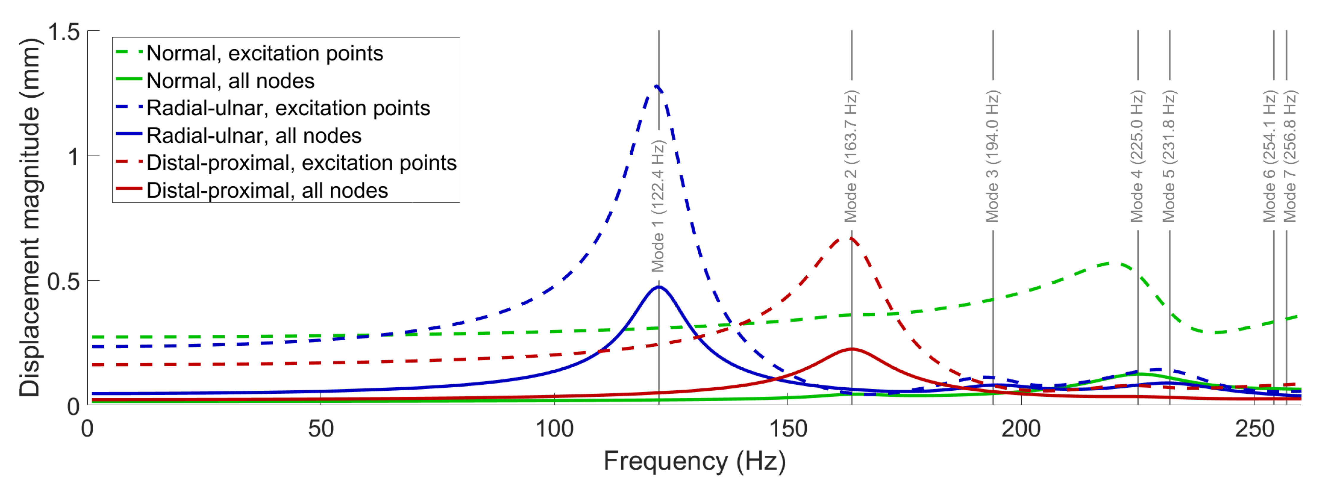
In this section, we present the frequency-response function (FRF) curves for the displacement magnitude () of the fingerprint centroid, computed through the frequency-response analyses. To cover all identified free vibration modes, we swept the loading frequency from 1 to 260 Hz with an increment of 1 Hz.
Figure 6 shows the results of the FRF computations performed for each load type diagrammed in
Figure 5; for each experiment, we separately report the average displacement of the nine nodes where force was applied and the average overall displacement of the entire model. The results show that major resonances occur around the first (122.4 Hz) and second (163.7 Hz) modes under radial–ulnar and distal–proximal vibrations, respectively. Furthermore, the FRF curves for the normal force both have peaks around 225 Hz due to the excitation of the fourth mode. The third, fifth, sixth, and seventh modes are not efficiently excited with normal excitation due to their low displacement magnitudes in the region of the fingerprint centroid. Compared to the normal excitation, dynamic amplification at the resonances is stronger for tangential loading, possibly due to the lack of bone support beneath the skin during lateral deformation.
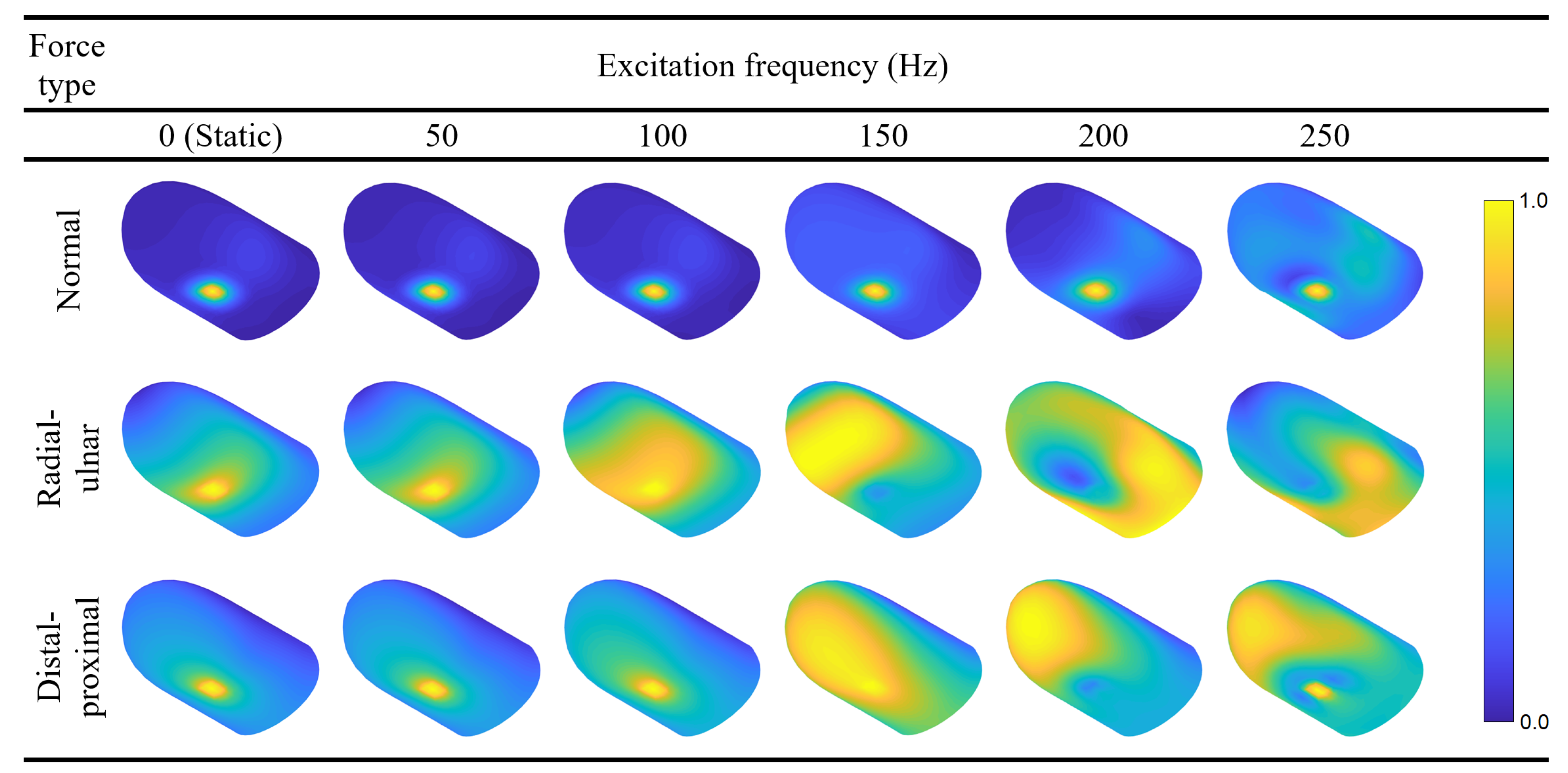
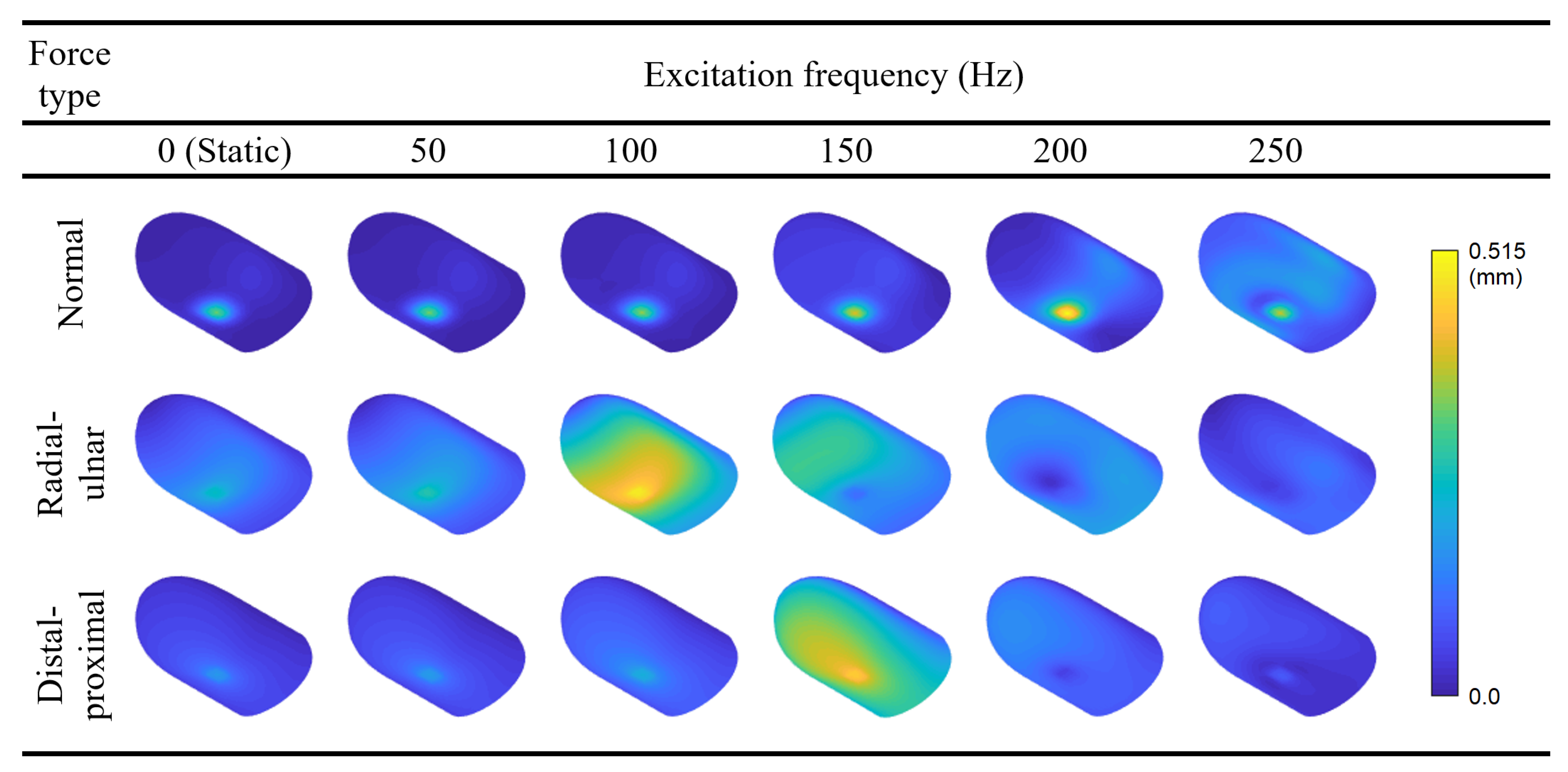
5.3. Forced Vibration Modes at 50, 100, 150, 200, and 250 Hz
Following the FRF calculations, we present the static deflection shape and forced vibration mode shapes at 50, 100, 150, 200, and 250 Hz for each loading direction (
Figure 7). The contours are colored with respect to the relative displacement magnitudes within each mode to ensure the visibility of mode shapes with smaller displacements. Readers may refer to
Video S2 in the supplementary materials and
Figure A2 in
Appendix A to see the animation of the forced vibration modes and the contours colored according to their absolute displacement magnitudes, respectively. The results indicate that the deflection is concentrated around the loading region for the majority of the cases. However, maximum displacement occurs at other locations for radial–ulnar excitation at 150, 200, and 250 Hz. This behavior is caused by the excitation of modes that have their largest relative displacement away from the fingerprint centroid. A similar case is observed for the distal–proximal excitation at 200 Hz. Resonance effects that induce maximum deformations distant from the excitation source have also been reported in the literature [
37].
Interestingly, the FRF curves for the normal force also show a slight increase at around 160 Hz, indicating the weak excitation of the second mode, which involves movement of distal finger tissue in the vertical direction. We believe that the influence of this mode was indirectly observed in a previous investigation by Wu et al. [
38]. In that study, for the fingertip exposed to harmonic plane vibrations around 100 Hz, a resonance is reported to cause the largest displacements close to the tip. We attribute the discrepancy between the two resonance frequencies to the differences between the two FE models. Within DigiTip, we utilized many additional parameters to include the details of the nail bed and the characteristic shape of the distal phalanx. We also used smaller width and height, and a thicker stratum corneum, all of which tend to increase the associated resonant frequencies. When interpreting particular phenomena associated with forced vibration responses such as the aforementioned resonances, it is highly advantageous to possess information about free vibration characteristics.
6. Conclusions
This study focuses on the dynamic analysis of a human fingertip through computational simulations. We developed an inhouse finite element analytical framework capable of generating 3D finger models and performing free and forced vibration analyses. The resulting finite element model of the fingertip, DigiTip, includes the details of six tissue layers (stratum corneum, epidermis, dermis, hypodermis, nail bed, and fingernail) and the characteristic profile of the distal phalanx, which is the bone supporting the fingertip.
We performed modal analyses to determine the free vibration modes with associated frequencies below or around 250 Hz. Seven characteristic vibration patterns were found in the frequency range of interest. Next, we utilized frequency-response analyses to predict forced vibration responses of the fingertip excited by harmonic forces applied on a small patch of skin at the fingerprint centroid in three orthogonal directions. The forced vibration analyses revealed that certain free vibration modes tend to be excited significantly more efficiently than the others under these conditions. The results give valuable insight into the probable dynamic behavior of the fingertip in haptic applications involving vibratory feedback, and they show the usability of modal information in predicting the forced vibration responses of soft-tissue.
In future studies, we plan to conduct experiments with human fingers to analyze the coherence between real measurements and our simulations. We hypothesize that some variations in tactile perceptual capabilities may be caused by differences in the physical structure and properties of the fingertip itself, as these clearly impact the fingertip’s resonant modes. Consequently, the sensitivity of the results to changes in key model parameters (e.g., finger dimensions, elastic moduli of the tissue layers) will be investigated. We also aim to consider scenarios involving multiple excitations at different locations and examine internal strains around the mechanoreceptor locations. As previously demonstrated by [
4] and others, we believe the simulated strains can be used as input for neural models to predict tactile responses of the skin subjected to dynamic forces.
Supplementary Materials
The following are available online at
https://www.mdpi.com/article/10.3390/app11125709/s1:
Video S1. An animation showing the first seven natural modes of the fingertip. One full cycle is shown for each mode, synchronized for comparison, even though their actual frequencies differ.
Video S2. An animation showing the forced vibration modes of the fingertip excited by dynamic forces with different directions and frequencies. One full cycle is shown for each mode, synchronized for comparison, even though their actual frequencies differ. Since the excitation amplitude is 0.1 N, the deformations are small but still observable on close inspection.
Author Contributions
Conceptualization, G.S. and K.J.K.; formal analysis, G.S.; investigation, G.S.; methodology, G.S. and K.J.K.; software, G.S.; supervision, K.J.K.; validation, G.S.; visualization, G.S. and K.J.K.; writing—original-draft preparation, G.S. and K.J.K.; writing—review and editing, G.S. and K.J.K. Both authors have read and agreed to the published version of the manuscript.
Funding
This research received no external funding. The article processing charge was covered by the Max Planck Digital Library.
Institutional Review Board Statement
Not applicable.
Informed Consent Statement
Not applicable.
Data Availability Statement
The data presented in this study are available on request from the corresponding author.
Acknowledgments
The authors thank Yasemin Vardar for recommending useful references.
Conflicts of Interest
The authors declare no conflict of interest.
Abbreviations
The following abbreviations are used in this manuscript:
| 2D | Two-dimensional |
| 3D | Three-dimensional |
| FE | Finite element |
| FRF | Frequency-response function |
Appendix A. Additional Results
Figure A1.
DigiTip’s first seven mode shapes and corresponding natural frequencies for an alternative model configuration, in which the rear boundary is entirely restrained. The contours indicate equivalent displacement magnitudes. In comparison with the results from the free boundary condition in
Figure 4, the nodes along the boundary remain fixed (dark blue color), but the general shapes and the order of the seven modes do not change.
Figure A2.
The recolored contours of the forced vibration mode shapes shown in
Figure 7. Here, the coloring shows the absolute displacement magnitudes so that the plots can be compared to one another.
Figure A2.
The recolored contours of the forced vibration mode shapes shown in
Figure 7. Here, the coloring shows the absolute displacement magnitudes so that the plots can be compared to one another.
References
- Johansson, R.S.; Vallbo, A.B. Tactile sensibility in the human hand: Relative and absolute densities of four types of mechanoreceptive units in glabrous skin. J. Physiol. 2000, 286, 283–300. [Google Scholar] [CrossRef]
- Löfvenberg, J.; Johansson, R.S. Regional differences and interindividual variability in sensitivity to vibration in the glabrous skin of the human hand. Brain Res. 1984, 301, 65–72. [Google Scholar] [CrossRef]
- Srinivasan, M.A. Surface deflection of primate fingertip under line load. J. Biomech. Eng. 1989, 22, 343–349. [Google Scholar] [CrossRef]
- Dandekar, K.; Raju, B.I.; Srinivasan, M.A. 3-D finite-element models of human and monkey fingertips to investigate the mechanics of tactile sense. J. Biomech. Eng. 2003, 125, 682–691. [Google Scholar] [CrossRef] [PubMed]
- Dzidek, B.M.; Adams, M.J.; Andrews, J.W.; Zhang, Z.; Johnson, S.A. Contact mechanics of the human finger pad under compressive loads. J. R. Soc. Interface 2017, 14, 20160935. [Google Scholar] [CrossRef] [PubMed]
- Kurita, Y.; Ikeda, A.; Ueda, J.; Ogasawara, T. A fingerprint pointing device utilizing the deformation of the fingertip during the incipient slip. IEEE Trans. Robot. 2005, 21, 801–811. [Google Scholar] [CrossRef]
- Prattichizzo, D.; Chinello, F.; Pacchierotti, C.; Malvezzi, M. Towards wearability in fingertip haptics: A 3-DoF wearable device for cutaneous force feedback. IEEE Trans. Haptics 2013, 6, 506–516. [Google Scholar] [CrossRef] [PubMed]
- Pacchierotti, C.; Prattichizzo, D.; Kuchenbecker, K.J. Cutaneous feedback of fingertip deformation and vibration for palpation in robotic surgery. IEEE Trans. Biomed. Eng. 2016, 63, 278–287. [Google Scholar] [CrossRef] [PubMed]
- Bolanowski, S.J.; Gescheider, G.A.; Verrillo, R.T.; Checkosky, C.M. Four channels mediate the mechanical aspects of touch. J. Acoust. Soc. Am. 1988, 84, 1680–1694. [Google Scholar] [CrossRef] [PubMed]
- Wu, J.Z.; Dong, R.G.; Smutz, W.P.; Schopper, A.W. Modeling of time-dependent force response of fingertip to dynamic loading. J. Biomech. 2003, 36, 383–392. [Google Scholar] [CrossRef]
- Wu, J.Z.; Krajnak, K.; Welcome, D.E.; Dong, R.G. Analysis of the dynamic strains in a fingertip exposed to vibrations: Correlation to the mechanical stimuli on mechanoreceptors. J. Biomech. 2006, 39, 2445–2456. [Google Scholar] [CrossRef]
- Shao, Y.; Hayward, V.; Visell, Y. Spatial patterns of cutaneous vibration during whole-hand haptic interactions. Proc. Natl. Acad. Sci. USA 2016, 113, 4188–4193. [Google Scholar] [CrossRef] [PubMed]
- Panchal, R.; Horton, L.; Poozesh, P.; Baqersad, J.; Nasiriavanaki, M. Vibration analysis of healthy skin: Toward a noninvasive skin diagnosis methodology. J. Biomed. Opt. 2019, 24, 015001. [Google Scholar] [CrossRef] [PubMed]
- Serina, E.R.; Mote, C.D., Jr.; Rempel, D. Force response of the fingertip pulp to repeated compression-effects of loading rate, loading angle and anthropometry. J. Biomech. 1997, 30, 1035–1040. [Google Scholar] [CrossRef]
- Pejović-Milić, A.; Brito, J.A.; Gyorffy, J.; Chettle, D.R. Ultrasound measurements of overlying soft tissue thickness at four skeletal sites suitable for in vivo x-ray fluorescence. Med. Phys. 2002, 29, 2687–2691. [Google Scholar] [CrossRef]
- Buryanov, A.; Kotiuk, V. Proportions of hand segments. Int. J. Morphol. 2010, 28, 755–758. [Google Scholar] [CrossRef]
- Mintalucci, D.; Lutsky, K.F.; Matzon, J.L.; Rivlin, M.; Niver, G.; Beredjiklian, P.K. Distal interphalangeal joint bony dimensions related to headless compression screw sizes. J. Hand Surg. 2014, 39, 1068–1074. [Google Scholar] [CrossRef] [PubMed]
- Jung, J.W.; Kim, K.S.; Shin, J.H.; Kwon, Y.J.; Hwang, J.H.; Lee, S.Y. Fingernail configuration. Arch. Plast. Surg. 2015, 42, 753–760. [Google Scholar] [CrossRef]
- Wang, L.; Yuan, S. A simple and direct procedure for excision of peripheral skin above the nail root to enable nail lengthening after fingertip amputation. J. Plast. Reconstr. Aesthet. Surg. 2012, 65, e265–e266. [Google Scholar] [CrossRef]
- Bennett, E.A.; Crevecoeur, I.; Viola, B.; Derevianko, A.P.; Shunkov, M.V.; Grange, T.; Maureille, B.; Geigl, E.-M. Morphology of the Denisovan phalanx closer to modern humans than to Neanderthals. Sci. Adv. 2019, 5, eaaw3950. [Google Scholar] [CrossRef]
- Wollina, U.; Berger, M.; Karte, K. Calculation of nail plate and nail matrix parameters by 20 MHz ultrasound in healthy volunteers and patients with skin disease. Skin Res. Technol. 2001, 7, 60–64. [Google Scholar] [CrossRef] [PubMed]
- Fruhstorfer, H.; Abel, U.; Garthe, C.-D.; Knüttel, A. Thickness of the stratum corneum of the volar fingertips. Clin. Anat. 2000, 13, 429–433. [Google Scholar] [CrossRef]
- Darowish, M.; Brenneman, R.; Bigger, J. Dimensional analysis of the distal phalanx with consideration of distal interphalangeal joint arthrodesis using a headless compression screw. Hand 2015, 10, 100–104. [Google Scholar] [CrossRef] [PubMed]
- Usami, S.; Okazaki, M.; Nitta, T.; Uemura, N.; Homma, T.; Akita, K. Histological investigation of common insensate flaps obtained from the hand and forearm regions for use in fingertip reconstruction. J. Plast. Surg. Hand Surg. 2017, 51, 182–186. [Google Scholar] [CrossRef]
- Somer, D.D.; Perić, D.; de Souza Neto, E.A.; Dettmer, W.G. A multi-scale computational assessment of channel gating assumptions within the Meissner corpuscle. J. Biomech. 2015, 48, 73–80. [Google Scholar] [CrossRef]
- Marks, R.M.; Barton, S.P. The Physical Nature of the Skin; MTP Press: Norwell, MA, USA, 1988; pp. 206–207. [Google Scholar]
- Störchle, P.; Müller, W.; Sengeis, M.; Lackner, S.; Holasek, S.; Fürhapter-Rieger, A. Measurement of mean subcutaneous fat thickness: Eight standardised ultrasound sites compared to 216 randomly selected sites. Sci. Rep. 2018, 8, 16268. [Google Scholar] [CrossRef]
- Mckittrick, J.; Chen, P.-Y.; Bodde, S.G.; Yang, W.; Novitskaya, E.E.; Meyers, M.A. The structure, functions, and mechanical properties of keratin. JOM 2012, 64, 449–468. [Google Scholar] [CrossRef]
- Liu, G.R.; Quek, S.S. The Finite Element Method: A Practical Course, 1st ed.; Butterworth-Heinemann: Oxford, UK, 2003; pp. 209–215. [Google Scholar]
- Lee, H.; Park, H.; Serhat, G.; Sun, H.; Kuchenbecker, K.J. Calibrating a soft ERT-based tactile sensor with a multiphysics model and sim-to-real transfer learning. In Proceedings of the 2020 IEEE International Conference on Robotics and Automation (ICRA), Paris, France, 31 May–31 August 2020; pp. 1632–1638. [Google Scholar]
- Serhat, G.; Basdogan, I. Design of curved composite panels for optimal dynamic response using lamination parameters. Compos. Part B Eng. 2018, 147, 135–146. [Google Scholar] [CrossRef]
- Turner, C.H.; Rho, J.; Takano, Y.; Tsui, T.Y.; Pharr, G.M. The elastic properties of trabecular and cortical bone tissues are similar: Results from two microscopic measurement techniques. J. Biomech. 1999, 32, 437–441. [Google Scholar] [CrossRef]
- Harris, C.M.; Piersol, A.G. Harris’ Shock and Vibration Handbook; McGraw-Hill: New York, NY, USA, 2002; pp. 2.3–2.30. [Google Scholar]
- Yildiz, M.Z.; Güçlü, B. Relationship between vibrotactile detection threshold in the Pacinian channel and complex mechanical modulus of the human glabrous skin. Somatosens. Mot. Res. 2013, 30, 37–47. [Google Scholar] [CrossRef]
- Wiertlewski, M.; Hayward, V. Mechanical behavior of the fingertip in the range of frequencies and displacements relevant to touch. J. Biomech. 2012, 45, 1869–1874. [Google Scholar] [CrossRef] [PubMed]
- Pacchierotti, C.; Sinclair, S.; Solazzi, M.; Frisoli, A.; Hayward, V.; Prattichizzo, D. Wearable haptic systems for the fingertip and the hand: Taxonomy, review, and perspectives. IEEE Trans. Haptics 2017, 10, 580–600. [Google Scholar] [CrossRef] [PubMed]
- Wu, J.Z.; Welcome, D.E.; Krajnak, K.; Dong, R.G. Finite element analysis of the penetrations of shear and normal vibrations into the soft tissues in a fingertip. Med. Eng. Phys. 2007, 29, 718–727. [Google Scholar] [CrossRef] [PubMed]
- Wu, J.Z.; Krajnak, K.; Welcome, D.E.; Dong, R.G. Three-dimensional finite element simulations of the dynamic response of a fingertip to vibration. J. Biomech. Eng. 2008, 130, 054501. [Google Scholar] [CrossRef] [PubMed]
| Publisher’s Note: MDPI stays neutral with regard to jurisdictional claims in published maps and institutional affiliations. |
© 2021 by the authors. Licensee MDPI, Basel, Switzerland. This article is an open access article distributed under the terms and conditions of the Creative Commons Attribution (CC BY) license (https://creativecommons.org/licenses/by/4.0/).


