Article

Optimization of Shunted Loudspeaker for Sound Absorption by Fully Exhaustive and Backtracking Algorithm

School of Mechanical & Automobile Engineering, Qingdao University of Technology, No. 777 Jialingjiang Road, Qingdao 266520, China
*
Author to whom correspondence should be addressed.
Appl. Sci. 2021, 11(12), 5574; https://doi.org/10.3390/app11125574
Submission received: 9 May 2021 / Revised: 27 May 2021 / Accepted: 13 June 2021 / Published: 16 June 2021
(This article belongs to the Special Issue Acoustic Properties of Absorbing Materials)

Abstract

:
The shunted loudspeaker with a negative impedance converter is a physical system with multiple influencing parameters. In this paper, a fully exhaustive backtracking algorithm was used to optimize these parameters, such as moving mass, total stiffness, damping, coil inductance, force factor, circuit resistance, inductance and capacitance, in order to obtain the best sound absorption in a specific frequency range. Taking the maximum average sound absorption coefficient in the range of 100–450 Hz as the objective function, the optimized parameters of the shunted loudspeaker were analyzed. Simulation results indicated that the force factor and moving mass can be sufficiently reduced in comparison with that of a typical four-inch loudspeaker available on the market. For a given loudspeaker from the market as an example, the four optimized parameters of the shunted loudspeaker were given, and the sound absorption coefficient was measured for verification. The measured results were in good agreement with the predicted results, demonstrating the applicability of the algorithm.

1. Introduction

Low-frequency sound absorption within a limited space is always a challenge in noise control engineering. Traditional passive acoustic structures usually have the disadvantage of being large in size, but active noise control technology also has drawbacks, such as instability and high cost. In recent years, the semi-active structure of a shunted loudspeaker (SL) for sound absorption has attracted much attention. For an SL with a negative impedance converter (NIC), the circuit parameters, such as resistance, capacitance and inductance, are transformed due to the negative impedance converter. This can effectively adjust the acoustic impedance of the coupled system to match that of the air in a wide frequency range [1]. Initially, Forward [2] proposed a preliminary experiment on the feasibility of using shunted damping in optical systems. Lissek et al. [3,4,5,6] introduced shunt circuits to loudspeakers and used the SL to control the acoustic impedance of walls for indoor sound absorption. Good sound absorption for low frequencies can be achieved in a relatively narrow frequency band. In their later research, analogous analysis, experimental optimization of the SL and active control theory were also carried out. Due to the low-frequency sound absorption properties of the SL, many structures relevant to the SL that have better sound absorption performance have been reported [7,8,9,10].
Some references can be found for the optimal design of an SL. Lissek et al. [5] established a low-order polynomial function and the effect of four parameters on sound absorption was investigated by using the response surface method (RSM). These four parameters were the moving mass of the loudspeaker, the enclosure volume, the filling density of mineral fiber within the enclosure and the electrical load value to which the loudspeaker was connected. Rivet et al. [11] introduced the SL for interior damping optimization and they determined the interior eigenfrequency by using a finite element model established in COMSOL Multiphysics. They also calculated the optimal location and orientation of the loudspeaker by establishing the linear equations of the system. Liu et al. [12] applied the SL to the pipe by means of a polar configuration of the system’s characteristic equations. The optimal resistance, inductance and location of the SL were derived. This method effectively improved the insertion loss of the pipe. Zhang et al. [13] analyzed the effect of the circuit resistance, inductance and capacitance (RLC) on the acoustic impedance and absorption coefficient of the SL in detail. They provided an experimental procedure for achieving effective broadband sound absorption from the low to the middle frequency range. An array of 64 SLs was experimentally investigated by Qiu et al. [14], and the optimal array alignment spacing, to control 100 Hz and 200 Hz tone noise, was also discussed.
The loudspeaker in a reported SL is oriented for sound generation. This means that this type of loudspeaker would not be suitable for optimal sound absorption due to its large force factor and moving mass. Designing a loudspeaker from the perspective of sound absorption has not been reported in the literature. To achieve this task, the loudspeaker and shunt circuit parameters must be taken into account. Since the SL is a coupled field consisting of electrical, mechanical and acoustic components, the system contains a large number of parameters and potential interactions among these parameters. The problem of multi-parameter optimization is rather complex.
The fully exhaustive backtracking algorithm (EBA) is a programming method frequently used in programming design. EBA is often applied to solve the problems that cannot be solved by conventional mathematical methods [15]. The fully exhaustive algorithm allows multivariate functions, with potential interactions, to be solved numerically according to a combined enumeration [16]. After the multi-dimensional database is created by the fully exhaustive method, the backtracking algorithm is then used to search for the target value by using loop traversal according to the optimal conditions [17]. Genetic algorithms (GA) and simulated annealing algorithms (SAA) are stochastic optimization algorithms that are based on probabilistic convergence [18]. In the optimization process of multi-peaked objective functions, GA and SAA may converge to a local optimal solution prematurely, and there is no effective quantitative analysis method for the convergence and reliability of the solution [19,20]. The global search feature of the EBA can effectively avoid these disadvantages. Although the EBA has the advantage of a simple computational process, it usually has the disadvantage of requiring a large amount of computing resources. In SL optimization problems, the amount of computation required is very limited; therefore, the EBA is well suited for SL multi-parameter optimization.
In this paper, six main parameters of the SL, namely moving mass Δ M m , system stiffness Δ K m , force factor B l , total resistance Δ R , total inductance Δ L and capacitance C e , are considered in an optimization algorithm. In the following section, the principle of the SL is introduced briefly; then, an optimized sound absorption algorithm based on a six-dimensional EBA is described, and the simulation and analysis of the loudspeaker parameters suitable for sound absorption are demonstrated. For a given loudspeaker from the market, the experimental method to determine the key parameters of the loudspeaker by an impedance tube is provided, and, finally, the optimization results of the four parameters are verified by an experiment.

2. Theoretical Model of an SL

The layout of a typical SL is shown in Figure 1 and the technical date of the loudspeaker used in the experiment are listed in Table 1. The SL with an NIC is assembled at the end of the impedance tube, and the effective absorption can be achieved after reasonable adjustment of the electrical parameters. From an energy perspective, it can be understood that the sound energy is dissipated in the form of mechanical and electrical energy, reducing the reflected sound energy and achieving the purpose of sound absorption.
When the SL is in an open-circuit state, it can be considered a single-degree-of-freedom, second-order system, which consists of stiffness, mass and damping [21]. The mechanical impedance under the case of an air cavity of depth D can be expressed as:
Z m = δ m + j ω M m + 1 j ω K m + ρ 0 c 0 A i tan ( k D )
where ω is the angular frequency, c 0 is the speed of sound in air, M m , K m , δ m are the moving mass, suspension diaphragm stiffness and damping of the moving-coil loudspeaker, respectively. Z a i r = ρ 0 c 0 A is the acoustic impedance of air, and A is the cross-section area of the impedance tube. k is the wavenumber and D is the cavity depth, where a more specific impedance expression can be obtained after making a second-order approximation to tan ( k D ) 1 [22]:
Z m ( ω ) = δ m + j ω ( M m + ρ 0 A D 3 ) + ( K m + ρ 0 c 0 2 A D ) / j ω
From Equation (2), it can be seen in the acoustic model of the SL with an air cavity that the total stiffness is the sum of the suspension diaphragm stiffness and the air spring of the air cavity, where the second item dominates. For example, a cylindrical cavity with a depth of 10 cm and radius of 5 cm can produce a stiffness of 11 KN/m, while a four-inch loudspeaker’s diaphragm stiffness is generally 1 KN/m. The total vibrating mass is the sum of the mechanical vibrating mass and one-third of the cavity air mass; the latter is usually negligible.
An NIC can generate the equivalent value of a negative electrical parameter between the in-phase input and ground [23]. It can flexibly adjust the impedance caused by a larger resistance and inductance of the loudspeaker itself, enabling impedance of the SL to match with air over a wider frequency band. When connecting the SL with an NIC, the impedance of the circuit is:
Z e ( ω ) = ( R c R ) + j ω ( L c L ) + 1 j ω C
The following is a derivation of the electrical force and impedance analogy. When the sound waves are transmitted to the loudspeaker’s diaphragm, it will produce a vibration with speed of v . The loudspeaker’s coil will cut the magnetic field of the permanent magnet, producing an induced electrical potential B l v . As the induced current is B l v / Z e , the electromagnetic force applied to the coil is F e = B 2 l 2 v / Z e . The equivalent mechanical impedance induced by the circuit can be obtained by Z Δ m ( ω ) = F e / v = ( B l ) 2 / Z e ( ω ) . Here, the total impedance of the SL can be expressed as:
Z s y s ( ω ) = Z m ( ω ) + ( B l ) 2 / Z e ( ω )
The normal incident absorption coefficient of the SL is:
α ( ω ) = 1 | Z s y s Z a i r Z s y s + Z a i r | 2 = 4 Z a i r Re ( Z s y s ) [ Z a i r + Re ( Z s y s ) ] 2 + Im ( Z s y s ) 2
Equation (5) shows that the sound absorption of the SL depends on the acoustic impedance of the system. The impedance matching condition should be satisfied when the sound is completely absorbed:
Re ( Z s y s ) = δ m + ( B l ) 2 Δ R Δ R 2 + ( ω Δ L 1 / ω C ) 2 = ρ 0 c 0 A
Im ( Z s y s ) = ω M m Δ K m ω ( B l ) 2 ( ω Δ L 1 / ω C ) Δ R 2 + ( ω Δ L 1 / ω C ) 2 = 0
where Δ R = R e R , Δ L = L e L and Δ K m = K m + ρ 0 c 0 2 A / D . The connection of the shunt circuit introduces new mechanical resistance and reactance. These parameters are mostly constant for the actual device, but the total impedance of the system changes with frequency. It is impractical to achieve an exact theoretical match, so a comprehensive optimization of sound absorption, based on experimental and theoretical calculation, is needed.

3. Algorithm Model and Simulation of the EBA

3.1. Procedure of the Algorithm Model

Loudspeakers used in the SL are for sound absorption, not sound generation. In contrast, loudspeakers available on the market are always used for sound generation. From the perspective of sound absorption, the loudspeaker in the SL must be redesigned. Through the simple analysis of the loudspeaker parameters, a certain trend of sound absorption can be obtained. However, the parameters influencing the sound absorption are coupled with each other and are difficult to analyze from a numerical point of view. The EBA is a method to obtain the ideal solution by calculating and analyzing all possible scenarios within the constraint. It can be expressed as enumerating all possible combinations of parameters within the boundaries, according to the step size of each variable, and then performing numerical analysis. Therefore, Matlab’s powerful matrix solving capability can be used to perform the EBA. The optimal parameters for Δ R , Δ L , C e , Δ K m , M m , B l can be calculated by the EBA and then used as design values for the SL. The following describes the EBA optimization algorithm for six parameters.

3.1.1. Parameter Boundary

Since the algorithm corresponds to the actual physical system, a realistic boundary condition should be set for Δ R , Δ L , C e , Δ K m , M m , B l . The characteristic equations of this system can be obtained by stability analysis. According to the Rouse criterion, Δ R , Δ L and C e must be positive, which determines the lower boundary of the Δ R , Δ L and C e [24]. Usually, the resistance of a typical four-inch loudspeaker does not exceed 25 Ω . Considering the actual component size, Δ L , C e should be limited to the magnitude of m F and m H , respectively.
The upper boundary of the mechanical parameters can be set reasonably, according to the actual size of the speaker and the assembly model. Here, M m is limited to 10 g , Δ K m is limited to 1.95 × 10⁴ N / m , and B l is limited to 6 T m . It is necessary to set a reasonable step size for these six parameters in this calculation. If the step size is small, it will lead to long computation time or even be impossible to compute. By using multiple iterations of the EBA to improve the computational efficiency of the program, sufficiently accurate solutions can be obtained in a relatively short time.
Under excitation of sound pressure, the SL generates an output voltage. The transfer function of the circuit section is shown in Equation (8). The maximum amplification can be obtained at the resonant frequency of the circuit. The actual output voltage at resonance can be calculated by multiplying the output signal obtained from the experimental test with Equation (9). When the actual transmission voltage can maximize the op-amp saturation value, the balancing resistance R b can be determined [22].
G ( S ) = R b + R + s L R R c + s ( L L c ) 1 s C e ,   ω o = 1 ( L c L ) C e
| G ( ω 0 ) | = ( R b + R ) 2 + L 2 ( L c L ) C R c R

3.1.2. Database Creation

The nonlinearity of the damping δ m is usually difficult to predict accurately after assembly. To obtain an accurate theoretical calculation, the damping corresponding to the open circuit should be sampled for replacing the damping in Equation (2). The absorption coefficient at each frequency in any group within the boundary can be calculated in a nested cycle using Equations (2)–(5). Then, the absorption coefficients of each group are stored after taking the average values, and thus the database of the average absorption coefficients of the six-dimensional parameters of the SL is established.

3.1.3. Optimal Results of Δ R , Δ L , C e , Δ K m , M m , B l

Once the database is created, the optimal average absorption coefficient values, and structural parameters such as Δ R , Δ L , C e , Δ K m , M m , B l , can be searched in the database by the backtracking method. Thus, the circuit parameters R , L , C e , and the equivalent depth D of the air cavity required for the design, can be calculated. Then, the sound absorption performance of the multi-parameter SL can be analyzed.

3.2. Optimal Sound Absorption for a Six-Parameter SL

In this simulation, the frequency range was 100–450 Hz and the inner diameter of the impedance tube was 10 cm. The mechanical damping as a constant was used in calculations and had a value of 1.74 sN / m . The optimized absorption coefficient and acoustic impedance of a six-parameter SL are shown in Figure 2. As observed in Figure 2a, the optimized six-parameter SL had an excellent sound absorption coefficient close to 1 in a wide frequency range of 100–450 Hz. By the EBA optimization search, a matched acoustic resistance close to 1 and a flat acoustic reactance trending toward 0 can be obtained in the specified frequency range, as shown in Figure 2b,c, respectively. In addition, it can be found that the first resonance occurs at 120 Hz, which is due to the resistance being close to 1 and the reactance being close to 0 at this frequency. Similarly, the second resonance is located at approximately 320 Hz.
The optimized mechanical and electrical parameters of the SL by the six-dimensional EBA are listed in Table 2. The optimized results indicated that the moving mass and force factor were smaller than that of a typical loudspeaker available on the market. The decrease in force factor can effectively reduce the cost and the weight of the loudspeaker magnet. This would be an obvious potential benefit for practical applications. The results also revealed that the total stiffness was smaller than that of a typical SL reported in the literature. Lower stiffness suggests that the backing air cavity needs to be larger; for example, when the loudspeaker suspension diaphragm stiffness is 900 N/m, a cubic cavity with a side length of 23.5 cm is needed to provide the remaining stiffness.

3.3. Optimal Sound Absorption for a Five-Parameter SL

The optimization results of the six parameters showed that the loudspeaker suitable for optimal sound absorption has the advantage of smaller B l . In practical applications, the thickness of the loudspeaker should be as small as possible, which means that the B l should be as small as possible. As an example, for the value of B l set to 0.5   T m , is taken into account in the algorithm; thus, the optimization procedure becomes an EBA of the remaining five variables. The optimized mechanical and electrical parameters of the SL by the five-dimensional EBA are listed in Table 3. The theoretical absorption coefficients under this condition are shown in Figure 3, and the average absorption coefficient is up to 0.96.
Below 150 Hz, the system resistance is less than half of that of the air, and the absolute value of sound reactance deviates from the zero point, which together leads to a lower value of the sound absorption coefficient in this frequency band. The peak of sound absorption occurs around 300 Hz, where the system resistance is close to 1 and the system reactance trends towards 0, as shown in Figure 3b,c.
The optimized total stiffness shown in Table 3 is relatively small. In this case, when the loudspeaker’s suspension diaphragm stiffness is 900 N/m, a cubic cavity with a side length of 31.8 cm is required to provide the remaining stiffness. If the volume of the air cavity needs to be sufficiently reduced, the loudspeaker’s suspension diaphragm stiffness must be set relatively low. Compared with Table 2, when the B l becomes smaller, the total resistance and inductance are relatively reduced, and the required capacitance is increased.

4. Experiment of Optimal Sound Absorption for a Four-Parameter SL

Since there were no loudspeakers available that were specifically suitable for optimal sound absorption, a commercial loudspeaker was used for the experimental verification. Thus, only four parameters of the SL, namely Δ R , Δ L , C e , Δ K m , needed to be optimized. The experimental setup is shown in Figure 4 and a photograph of the setup is shown in Figure 5. The inside diameter of the impedance tube (SW422 (BSWA, Beijing, China)) was 100mm, and the noise signal generated by the computer was amplified by a power amplifier (PA50 (BSWA, Beijing, China)). When the loudspeaker is excited to emit a sound source, the end of the impedance tube uses a dual microphone (BSW416 (BSWA, Beijing, China)) to pick up the sound signal. The four-channel digital collector (MC3242 (BSWA, Beijing, China)) samples the signal and sends it to the computer for data processing. The loudspeaker (M4N (HiVi, Zhuhai, China)) was fixed at the end of the pipe by an air cavity equipped with a piston.
For the accurate establishment of an SL absorption model, the exact mechanical and electrical parameters of the loudspeaker need to be known. Generally, the factory-calibrated parameters of the loudspeaker are accurate, but the actual parameters will change after it is assembled due to the coupling influence in the impedance. After assembly, the damping of the loudspeaker is nonlinear and difficult to predict accurately [22]. This will lead to a mismatch between the results of the theoretical predictions and the actual experiments, so, in our experiment, the actual damping was used in the calculation. The following describes how to experimentally determine the values of Δ δ , Δ K m , M m , R c , L c , B L .

4.1. The Experiment of Parameter Determination

4.1.1. Determination of Mechanical Parameters

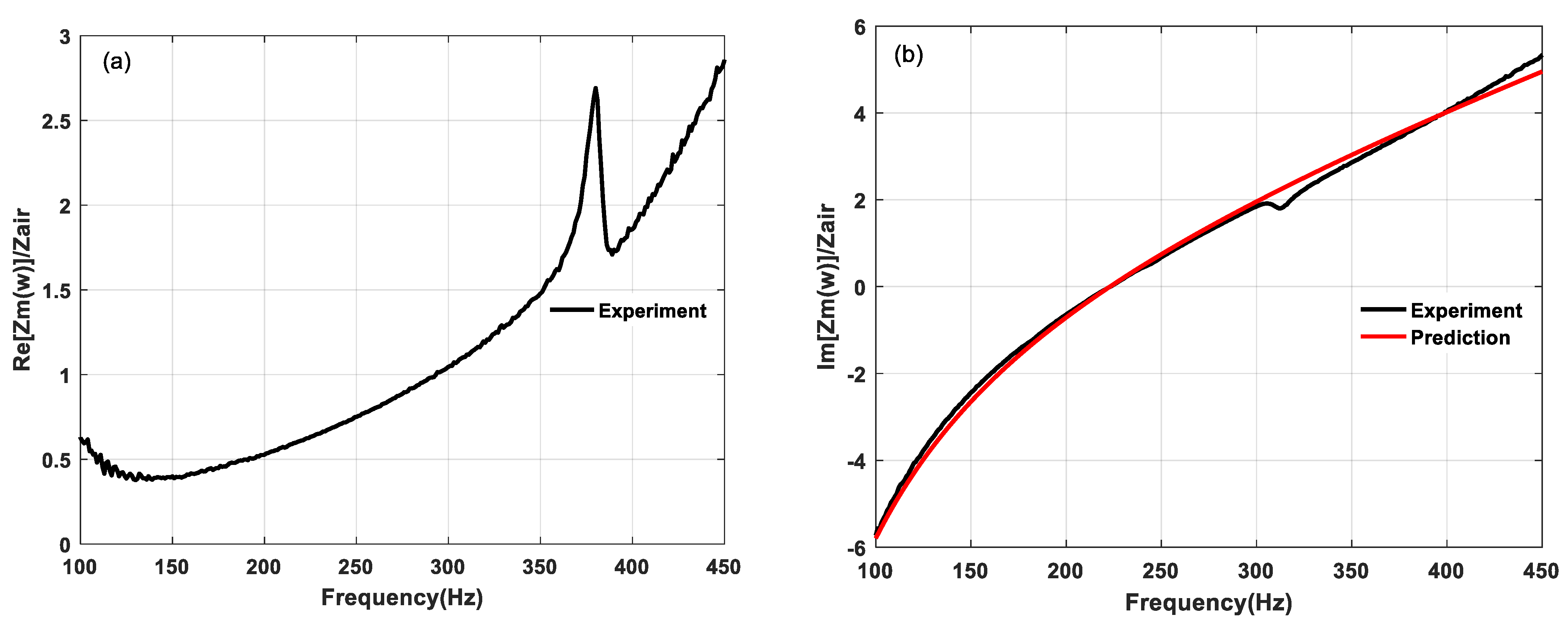
The loudspeaker was assembled at the end of the standing wave tube, in accordance with the open-circuit state. The cylinder piston was placed on the leftmost side. The resistance and reactance diagram is shown in Figure 6a,b. The theoretical equation of acoustic impedance is:
{ (10a) Im [ Z m ( ω ) ] = j ω M m + Δ K m / j ω (10b) Re [ Z m ( ω ) ] = δ m
As shown in Figure 6a, the actual resistance of the system was not a constant value, but a nonlinear function that is dependent on the frequency. There was a damping peak at 380 Hz, which was caused by the resonance of the mechanical system. According to Equation (10a), the reactance of the system was only related to the moving mass and stiffness. Therefore, the equivalent moving mass and stiffness can be calculated by fitting the measured acoustic reactance using the least squares method. The equivalent moving mass of the loudspeaker in this experiment was 7.5 g and the system stiffness was 14,724 N / m ; therefore, the three mechanical parameters of the loudspeaker could be accurately determined.

4.1.2. Determination of Electrical Parameters

The coil resistance R c can be measured directly using a Digital Multi-Meter. In contrast, the coil inductance L c has a frequency-dependent nonlinearity, so its value as determined by multi-meter measurement would be inaccurate. L c can be fitted under short-circuit states, and when the R c , L c , B l are introduced, the system acoustic impedance can be expressed as:
Z s h o r t = j ω [ M m ( B l ) 2 L c R c 2 + ω 2 L c 2 ] + [ δ m + ( B l ) 2 R c R c 2 + ω 2 L c 2 ] + Δ K m j ω
First, according to the frequency at the resonance peak and the absorption coefficient, the B l and the coil L c can be counted out at the resonance frequency f 0 , as shown in Equations (12) and (13).
f 0 = K s y s M s y s / 2 π = Δ K m M m ( B l ) 2 L c R e 2 + ω 0 2 L c 2 / 2 π
α 0 = 1 | Z s y s Z 0 Z s y s + Z 0 | 2 = 1 | j ω 0 ( M m ( B l ) 2 L c R c 2 + ω 0 2 L c 2 ) + ( δ m + ( B l ) 2 R c R c 2 + ω 0 2 L c 2 ) + Δ K m j ω 0 ρ 0 c 0 S j ω 0 ( M m ( B l ) 2 L c R c 2 + ω 0 2 L c 2 ) + ( δ m + ( B l ) 2 R c R c 2 + ω 0 2 L c 2 ) + Δ K m j ω 0 + ρ 0 c 0 S | 2
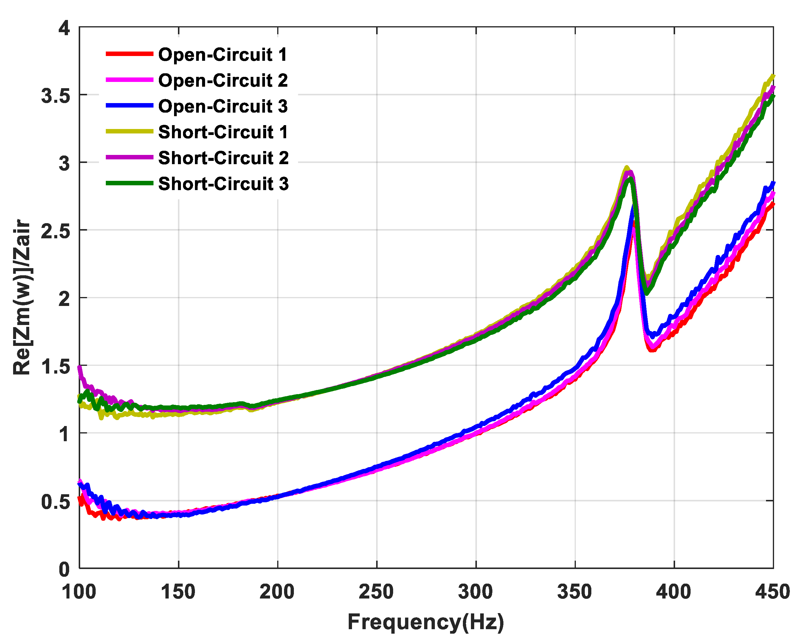
The resistance measured from the three sets of experiments for the short circuit and the open circuit are shown in Figure 7. According to Equations (10b) and (11), the resistance difference between the short circuit and the open circuit is expressed as ( B l ) 2 R e / ( R e 2 + ω 2 L e 2 ) . For a small signal input, B l can be regarded as a constant value. By using least squares method at each frequency, the theoretical value of L c can be calculated. The calculated B l was 4 T m , and L c was 0.68 m H . 
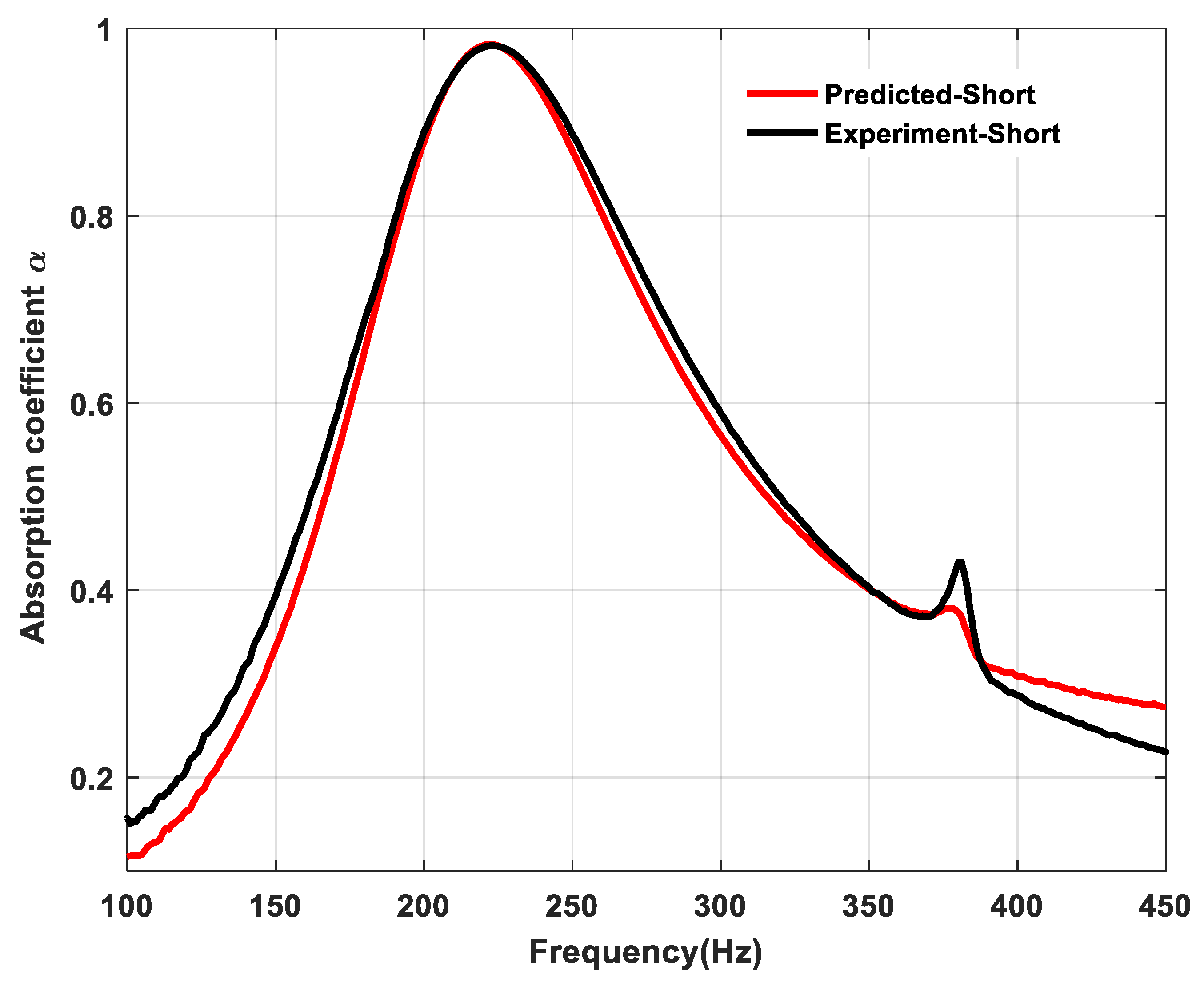
The actual parameters of the loudspeaker were all obtained. In Figure 8, the theoretical calculation results and the actual sound absorption results are shown to match better in the short-circuit state, which verifies the parameters obtained.

4.2. Experimental Results

The resistance obtained from the experiments in the open-circuit state was sampled and used in the optimization program as the actual damping. M m and B l obtained in the previous section were taken as fixed parameters. The optimization procedure thus becomes EBA about Δ R , Δ L , C e , Δ K m . The upper bound settings, step size settings and optimal parameters are shown in Table 4.
The experimental balance resistance R b is 1 Ω , and the selected operational amplifier is O P A 552 P A with a ±15 V 
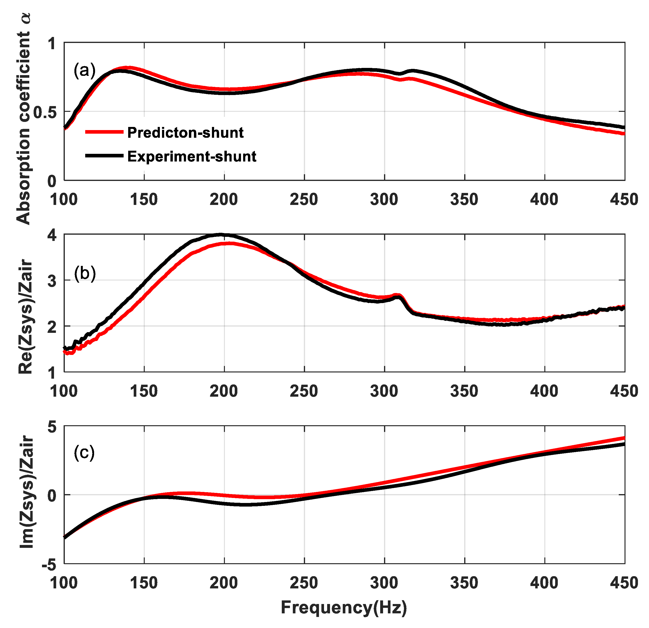
power supply. The experimental and theoretical predictions were in good agreement in the overall frequency band. As shown in Figure 9a, in the target frequency band, the average absorption coefficient was 0.65, and the overall absorption coefficient was improved compared with the short-circuit condition. However, due to the larger M m and B l of the loudspeaker, the SL was less adjustable. Compared with the open-circuit case in Figure 6b, the total reactance of the SL shown in Figure 9c was significantly lower over a wide frequency band, especially in the 150–300 Hz band, where it trended toward zero, which allowed the reactance to better meet the matching conditions. As shown in Figure 9b, the resistance below 450 Hz was much larger than the air acoustic resistance, so the SL over-damping limited further improvement of the sound absorption level.

4.3. Discussion

The experimental results of the four–parameter optimization showed that loudspeakers on the market have large values of moving mass and force factor, which limit the sound absorption performance improvement of the SL. The EBA optimization simulation indicated that a loudspeaker suitable for sound absorption should be characterized by small moving mass and force parameters. This would facilitate the miniaturization and design of a lightweight SL, as well as allowing for innovation in the loudspeaker structure. As shown in Equations (6) and (7), the introduction of the shunt circuit inevitably increases the acoustic resistance, while reducing the system acoustic reactance. Since excessive damping is a disadvantage for sound absorption, designing a loudspeaker with small amounts of linear damping should be the focus of future research. In addition, designing a large-area SL for diffuse field sound absorption would also be worth studying.

5. Conclusions

In order to obtain excellent sound absorption in the frequency range of 100–450 Hz, a fully exhaustive backtracking algorithm was proposed for optimizing the loudspeaker and shunt circuit parameters. For a given loudspeaker, the experimental method to determine its parameters was provided, and the optimal sound absorption algorithm under four parameters was verified by measurement. Through multiple-parameter optimization, it was found that the force factor and moving mass can be sufficiently reduced in comparison with that of a typical four-inch loudspeaker available on the market. The results imply that if an air cavity is properly sized, the SL can be redesigned to achieve good sound absorption, while also significantly reducing the weight and volume of the loudspeaker.

Author Contributions

Conceptualization, Z.L. and B.L.; Methodology, Data curation and Investigation, Z.L.; Validation and Software, Z.L. and X.L.; Resources and Supervision, B.L.; Writing—Original Draft Preparation, Z.L.; Writing—Review and Editing, Z.L. and X.L. All authors have read and agreed to the published version of the manuscript.

Funding

Financial support was given by NSFC through Grant No. 11874034, as well as the Taishan Scholar Program of Shandong (No.ts201712054). Both are highly appreciated.

Institutional Review Board Statement

Not applicable.

Informed Consent Statement

Not applicable.

Data Availability Statement

The data presented in this study are available on request from the corresponding author.

Conflicts of Interest

The authors declare no conflict of interest.

References

  1. Černík, M.; Mokry, P. Sound reflection in an acoustic impedance tube terminated with a loudspeaker shunted by a negative impedance converter. Smart Mater. Struct. 2012, 21, 115016. [Google Scholar] [CrossRef]
  2. Forward, R.L. Electronic damping of vibrations in optical structures. Appl. Opt. 1979, 18, 690–697. [Google Scholar] [CrossRef] [PubMed]
  3. Lissek, H.; Meynial, X. A preliminary study of an isodynamic transducer for use in active acoustic materials. Appl. Acoust. 2003, 64, 917–930. [Google Scholar] [CrossRef]
  4. Lissek, H.; Boulandet, R. Pierre-Jean René. Shunt loudspeakers for modal control in rooms. In Proceedings of the 16th International Congress on Sound and Vibration (ICSV), Krakow, Poland, 5–9 July 2009. [Google Scholar]
  5. Boulandet, R.; Lissek, H. Optimization of electroacoustic absorbers by means of designed experiments. Appl. Acoust. 2010, 71, 830–842. [Google Scholar] [CrossRef]
  6. Lissek, H.; Boulandet, R.; Fleury, R. Electroacoustic absorbers: Bridging the gap between shunt loudspeakers and active sound absorption. J. Acoust. Soc. Am. 2011, 129, 2968. [Google Scholar] [CrossRef] [PubMed] [Green Version]
  7. Tao, J.; Jiao, Q.; Qiu, X. A composite sound absorber with micro-perforated panel and shunted loudspeaker. Proc. Meet. Acoust. 2013, 19, 015068. [Google Scholar]
  8. Jing, R.; Tao, J.; Qiu, X. Sound absorption of a finite micro-perforated panel backed by a shunted loudspeaker. J. Acoust. Soc. Am. 2014, 135, 231. [Google Scholar]
  9. Zhang, Y.; Chan, Y.J.; Huang, L. Thin broadband noise absorption through acoustic reactance control by electro-mechanical coupling without sensor. J. Acoust. Soc. Am. 2014, 135, 2738–2745. [Google Scholar] [CrossRef] [PubMed] [Green Version]
  10. Cong, C.; Tao, J.; Qiu, X. A Multi-Tone Sound Absorber Based on an Array of Shunted Loudspeakers. Appl. Sci. 2018, 8, 2484. [Google Scholar] [CrossRef] [Green Version]
  11. Rivet, E.; Boulandet, R.; Lissek, H. Optimization of electroacoustic resonators for semi-active room equalization in the low-frequency range. J. Acoust. Soc. Am. 2013, 133, 3348. [Google Scholar] [CrossRef] [Green Version]
  12. Liu, W.; Mao, Q. Design of shunt loudspeaker by pole configuration method. Vib. Shock 2018, 37, 97–101. [Google Scholar]
  13. Zhang, Y.; Wang, C.; Huang, L. Tuning of the acoustic impedance of a shunted electro-mechanical diaphragm for a broadband sound absorber. Mech. Syst. Signal Process. 2019, 126, 536–552. [Google Scholar] [CrossRef]
  14. Zhang, P.; Cong, C.; Tao, J.; Qiu, X. Dual frequency sound absorption with an array of shunt loudspeakers. Sci. Rep. 2020, 10, 10806. [Google Scholar] [CrossRef] [PubMed]
  15. Sun, Y.; Feng, N. The application of exhaustive method in programming. Comput. Age 2012, 8, 50–52. [Google Scholar]
  16. Zhang, T.; Zhang, F.; Sheng, J. Study of Exhaustive Algorithm for the Unit Commitment Optimization. J. Qingdao Univ. Technol. 2011, 32, 87–92. [Google Scholar]
  17. Pei, N.; Bi, C. Application of Backtracking Method in Computer Programming. Comput. Knowl. Technol. 2017, 13, 262–264. [Google Scholar]
  18. Yang, H.; Lin, H. Summarization of Optimizations of Genetic Algorithm and Simulated Annealing Algorithm. Mach. Build. Autom. 2010, 73–75. [Google Scholar]
  19. Li, Y.; Yuan, H.; Yu, J.; Zhang, G.; Liu, K. A review on the application of genetic algorithm in optimization problems. Shandong Ind. Technol. 2019, 290, 242–245. [Google Scholar]
  20. Zhu, Y.; Zhong, Y. A Kind of Renewed Simulated Annealing Algorithm. Comput. Technol. Dev. 2009, 19, 32–35. [Google Scholar]
  21. Eargle, J. Loudspeaker Handbook, 2nd ed.; Kluwer Academic: Boston, MA, USA, 2003; Chapters 1–4; pp. 1–63. [Google Scholar]
  22. Zhang, Y. Dynamic Mass Modification by Electric Circuits. Master’s Thesis, University of Hong Kong, Pokfulam, Hong Kong, 2012. [Google Scholar]
  23. Yu, C. Negative impedance converter and its application in circuit experiments. Teach. Electr. Courses High. Educ. 1982, 54–57. [Google Scholar]
  24. Zhang, Y.; Chan, Y.; Huang, L. Low-frequency noise absorption by a shunted loudspeaker. In Proceedings of the 20th International Congress on Sound and Vibration (ICSV), Bangkok, Thailand, 7–11 July 2013. [Google Scholar]
Figure 1. Schematic of the shunted loudspeaker with an NIC.
Applsci 11 05574 g001
Figure 2. Optimized sound absorption of the SL by a six–dimensional EBA, (a) the sound absorption coefficient, (b) the specific acoustic resistance, (c) the specific acoustic reactance.
Applsci 11 05574 g002
Figure 3. Optimized sound absorption of the SL by a five–dimensional EBA, (a) the sound absorption coefficient, (b) the specific acoustic resistance, (c) the specific acoustic reactance.
Applsci 11 05574 g003
Figure 4. Experimental setup of the SL.
Applsci 11 05574 g004
Figure 5. Photograph of the experimental setup.
Applsci 11 05574 g005
Figure 6. Experimental impedance of the open circuit: (a) the specific acoustic resistance; (b) the specific acoustic reactance.
Applsci 11 05574 g006
Figure 7. Short-circuit and open-circuit resistance comparison.
Applsci 11 05574 g007
Figure 8. Short-circuit absorption coefficient comparison.
Applsci 11 05574 g008
Figure 9. Comparison of the four–dimensional EBA simulation and measurement: (a) the sound absorption coefficient, (b) the specific acoustic resistance, (c) the specific acoustic reactance.
Applsci 11 05574 g009
Table 1. Technical data for the loudspeaker Hivi–M4N.
B l R c L c M m K m δ m
3.1   T m 6.5   Ω 0.5   m H 4.8   g 926   N / m 1.74   s N / m
Table 2. Parameter upper bounds and step size settings.
ParameterUpper BoundStep SizeOptimal
Δ R 20   Ω 0.2   Ω 2   Ω
Δ L 5   m H 50   μ H 0.85   m H
C e 5   m F 50   μ F 0.7   μ F
Δ K m 1.95 × 10 4   N / m 390   N / m 1560   N / m
M m 10   g 0.2   g 1   g
B l 6   T m 0.2   T m 2.2   T m
Table 3. Parameter upper bounds and step size settings.
ParameterUpper BoundStep SizeOptimal
Δ R 20   Ω 0.2   Ω 0.2   Ω
Δ L 5   m H 50   μ H 0.15   m H
C e 5   m F 50   μ F 2   m F
Δ K m 1.95 × 10 4   N / m 390   N / m 1170   N / m
M m 10   g 0.1   g 0.5   g
Table 4. Parameter upper bounds and step size settings.
ParameterUpper BoundStep SizeOptimal
Δ R 25   Ω 0.1   Ω 1.6   Ω
Δ L 5   m H 50   μ H 1.6   m H
C e 5   m F 50   μ F 0.4   m F
Δ K m 1.8 × 10 4   N / m 360   N / m 11,880 N / m
Publisher’s Note: MDPI stays neutral with regard to jurisdictional claims in published maps and institutional affiliations.

