Abstract
In order to study the spallation phenomenon of titanium alloy under the shock of nanosecond laser, the Neodymium-Yttrium-Aluminum Garnet laser was used to carry out laser shock experiments on the surface of titanium alloy. By observing and measuring the surface morphology of the target material, the forming factors and the changes of the surface morphology under different parameter settings, the forming criteria of the titanium alloy were obtained. The results show that under the single variable method, the change of laser energy can affect the target shape variable, and there is a positive correlation between them. When the thickness was greater than or equal to 0.08 mm, no obvious cracks were found in the targets. Moreover, the number of impact times was the key factor for the target deformation; with the growth of impact times, the target deformation gradually became larger until the crack appeared. The larger the diameter of the spot, the more likely the target was to undergo plastic deformation. The surface of titanium alloy with a thickness of 0.08 mm appeared to rebound under specific laser shock condition. The changes in the back of the target material were observed in real time through a high-speed camera, and the plasma induced by the laser was observed in the process. This study is based on the results of previous studies to obtain the titanium alloy forming criteria, which provides a basis for the setting of laser parameters and the thickness of the target when the nanosecond laser impacts the Ti-6AL-4V target.
1. Introduction
Titanium alloy material is an important structural metal developed in the 1950s. The industrial production of titanium began in 1948, and the development of the aviation industry has led to rapid growth of the titanium industry. Countries are also developing new low-cost and high-performance titanium alloys, and strive to have titanium alloys enter the civil industry with huge market potential. In this context, higher requirements are put forward for the research into titanium alloy processing technology.
Laser shock forming is developed on the basis of laser shock processing technology. The interaction between laser and material produces high-pressure plasma. The plasma blast wave maintained by the laser energy propagates into the target material to form a shock wave, and the shock wave strikes the metal target. The effect of the shock wave causes the target material to undergo plastic deformation [1]. Different from ordinary stamping molding technology, laser impact forming technology makes small-scale metal material molding processing production more economical, not only saving human resources and production costs, but is also more widely applicable than ordinary stamping molding technology, suitable for ordinary metal materials and some non-processable metal materials. In recent years, researchers have conducted a lot of research on the material modification and plastic deformation of commonly used metals such as copper, aluminum and stainless steel under laser shock technology [2,3,4]. The Zhou Jianzhong team of Jiangsu University studied the influence of laser parameters and material selection on forming quality through a large number of experiments [5,6]. The study found that the deformation of the target material is positively correlated with the laser pulse energy, as well as the number of laser shocks. For different materials, the effect of laser shock on the surface hardness and microstructure of the material was analyzed experimentally. Cao Ziwen of Beijing Institute of Aeronautical Manufacturing Engineering [7] conducted experiments to study the bending deformation law and surface characteristics of aluminum alloy under laser-induced shock wave loading, and the study found that laser power density and coverage affect the size and distribution of plastic strain on the surface of the sample, which affected its bending deformation. Jiang Yinfang’s team from Jiangsu University [8] studied the thickness reduction rate criterion of aluminum alloy sheet under laser shock through simulation and experiment, and applied the fracture criterion to study the forming law of different sheet sizes under laser shock, and obtained the rule by studying the thickness reduction limit and forming depth limit of the sheet metal. Zhang Yan [9], from Anhui University of Technology, studied the semi-membrane multi-impact forming process of 2024 aluminum alloy sheet under laser loading through a combination of experiment and simulation, and discussed the impact of shock wave pressure, sheet thickness and other factors on plate forming. Xie Baohua [10] of Nanchang Aviation University used binary optics to change the distribution of laser spot light intensity, and discussed the forming limit and forming effect of 0.1 mm thickness titanium plates under different laser process parameters. However, the experimental research on these aspects of Ti-6AL-4V(TC4) titanium alloy is somewhat insufficient.
In this paper, TC4 titanium alloy is taken as the research object. The back deformation of the target material is measured by profilometer, and the influence of different laser parameters on the impact forming of the target material is compared. In addition, the whole process of laser impact is observed by a high-speed camera, and the causes of various phenomena at different times are analyzed. Moreover, the forming rules of TC4 titanium alloy under laser loading are obtained.
2. Materials and Methods
2.1. Experimental Scheme and Device
Laser shock uses high power density (109 W/cm2 magnitude) and short pulse width (10~30 ns magnitude) to irradiate the surface of the material through the transparent constrained overlay, so as to produce mechanical effects on the surface of the material. If the material has significant plastic deformation, it is called laser shock forming. In contrast, if there is no significant plastic deformation found on the surface of the target, and only the surface structure and mechanical properties of the target material are changed, it is called laser shock processing. According to the principle of laser shock processing [11], the authors of this research designed the experimental scheme shown in Figure 1.
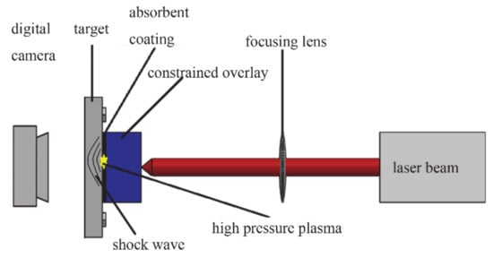
Figure 1.
Experimental scheme diagram.
In the experiment, the Neodymium-Yttrium-Aluminum Garnet laser produced by the French company Thales was used as the high-intensity pulse output device. The laser output a flat-topped distributed beam, and the laser beam was focused on the surface of the target through the focusing lens. The laser system parameters are shown in Table 1. The experimental sample material was TC4 titanium alloy with a size of 40 mm × 40 mm and a thickness ranging from 0.01 mm to 1.5 mm. Before the experiment, all targets were polished, and the polished targets were treated with anti-oxidation. The target material was clamped on the workbench; in order to facilitate the observation of the deformation of the target material during the experiment, a square hole fixture was selected in the experiment. The surface of the polished TC4 titanium alloy was covered with a layer of black tape approximately 130 μm as an absorption layer. Before the experiment, the distance between the laser head and the target surface to be processed was adjusted, to ensure that the surface of the target material to be processed was in the focus position of the laser, and by this method we manually adjusted the laser spot diameter of 5 mm and 7 mm, respectively [12]. A laser beam was focused on the surface of the target through a focusing lens, and a water curtain with a thickness of 2 mm was set to flow on the surface of the target. The water flow acted as a confinement layer, and the expansion of the high-pressure plasma was restricted by the water flow, which increased the shock wave between the confinement layer and the target material. The multiple reflections increased the impact force on the target material, and at the same time extended the effective time of the laser shock wave acting on the target material [13]. In the experiment, the pulse width of the laser was 10 ns.

Table 1.
Work parameters of the laser system.
In the experiment, a v2511 high-speed digital camera was used to record the morphological change process of the back of the target during the entire laser impact process. The high-speed digital camera was mounted on the back of the target, and the height and focal length of the high-speed digital camera were adjusted to ensure a clear view of the back of the target. Based on the situation, the highest shooting rate obtained was 8000 frames per second. The LJ-V7000 ultra-high-speed profile measuring instrument was used to measure and observe the two-dimensional topography of the back of the target after the experiment.
2.2. Numerical Simulation
The plastic deformation of metal materials under laser shock loading is an instantaneous, high-speed and nonlinear dynamic process. The characteristics of plastic forming of metal materials under high strain rates need to be considered in the simulation. ABAQUS/Explicit is a purpose-specific analysis module ideal for simulating short, instantaneous shocks and other highly discontinuous problems such as drop tests, ballistic shocks, explosions and other highly discontinuous problems [14].
During the simulation process, the TC4 titanium alloy target with a thickness of 0.08 mm was calculated. The laser spot diameter was 5 mm, combined with the principle of the action of laser and material, considering that the laser’s action area on the target was generally near the spot diameter, the photomagnetic diameter of 3–5 times the area of the laser action area. In order to simplify the model, a square TC4 titanium alloy with a side length of 20 mm was selected as the model. The response time in the model was set to be more than 100 times the pulse width [15], and the time increment step selected 1/10 of the pulse width [16]. Since the deformation process of the target material needs to be specifically observed, the interval in the analysis step was set to 100.
The Johnson-Cook damage model is suitable for the plastic deformation of metals at high strain rates. Therefore, the numerical simulation used this model to characterize the material parameters [17]. The peak pressure under the constrained layer was calculated using the classic R.Fabbro model [18], and the laser pulse in the model could be calculated at 2.8868 Gpa. Table 2 shows the Johnson-Cook model parameters of the TC4 titanium alloy, wherein ρ is the material density, E is the elastic modulus, v is the Poisson’s ratio, and A, B, C, n, and m are the material constants.
Table 2.
Johnson-Cook parameters of Ti-6AL-4V.
3. Results and Discussion
3.1. Influence of Thickness on Forming Effect
The spot diameter was selected to be 7 mm, and a 10 J single pulse laser was used to impact TC4 titanium alloy targets of different thicknesses. The target thicknesses were 0.01 mm, 0.03 mm, 0.05 mm, 0.08 mm, 0.3 mm, 0.5 mm, 0.8 mm, 1.0 mm, 1.2 mm and 1.5 mm respectively. The thickness of TC4 titanium alloy targets ranging from 0.01 mm to 0.5 mm had obvious plastic deformation, whereas the targets larger than 0.5 mm had no visible deformation. Figure 2a shows the back outline of targets with different thicknesses under the impact of 10 J laser pulses. Figure 2b exhibits the morphologies of the target material after a single impact deformation.
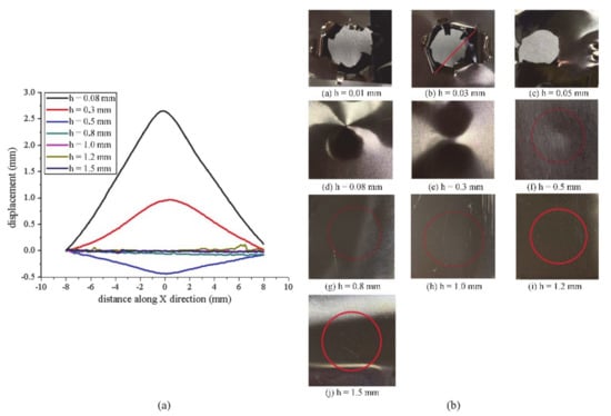
Figure 2.
(a) The outline of targets with different thicknesses. (b) The morphologies of target material with different thicknesses.
As shown in Figure 2, when the thickness of the target material was 0.01 mm, the target underwent plastic deformation and a petal-shaped small hole was present on the back of the target. As the laser spot was not placed at the center of the target material during experimental operation, the target material only presented its shape, and the specific value could not be measured. For 0.03 mm thickness target, there was a petal-shaped hole appearing on the back of the target, and the maximum tear size was about 20.1 mm. Compared with the target with 0.01 mm and 0.03 mm thickness, the 0.05 mm TC4 alloy target seemed to be different; it had a 6.4 mm aperture circle hole after laser impact, and the size was almost equal to the laser spot diameter. When the thickness of the target material was 0.08 mm, 0.3 mm and 0.5 mm respectively, the deformation profile curve of the target showed a gradually shrinking trend, and the corresponding maximum deformation decreased from 2.6915 mm to 0.9675 mm to 0.4334 mm. Since there was no deformation behind the target with a thickness of 0.5 mm, the deformation profile of the impact surface was measured. As is demonstrated in Figure 2, no plastic deformation occurs when the thickness of the target material is greater than 0.5 mm.
The laser irradiates the absorption layer on the surface of the target. The absorption layer quickly absorbs the laser energy and then vaporizes quickly. In the process of continuing to absorb the laser energy, the steam is easily heated and ionized into plasma, and the plasma propagates into the target to form a shock wave. As the thickness of the target material increases, the propagation distance of the laser-induced shock wave in the radial direction of the target material rises, causing the time for the shock wave to reach the free surface of the target material to increase. Then the attenuation of the shock wave in the process of propagation inside the target material increases, resulting in a gradual decrease in the deformation of the target material. Therefore, for the TC4 titanium alloy target, it is more difficult for the surface of the target to undergo plastic deformation with the increase of the target thickness, and when the thickness reaches a certain value, no significant plastic deformation is found on the surface of the target.
3.2. Influence of Spot Diameter on Forming Effect
Different spot diameters of 5 mm and 7 mm were selected, and a 10 J single pulse laser was used to impact TC4 titanium alloy targets with the same thickness. The target thicknesses were 0.08 mm and 0.3 mm. Figure 3 shows the back morphology of the target under different spot diameters.
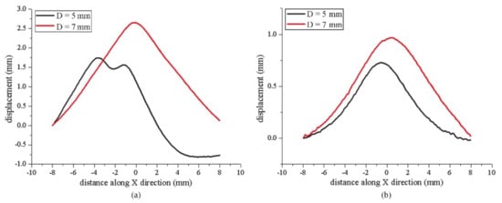
Figure 3.
(a) The outline of targets with 0.08 mm thickness. (b) The outline of targets with 0.3 mm thickness.
When h = 0.08 mm, the maximum deformation of the target under 5 mm spot diameter was 1.7406 mm, and the maximum deformation of the target under 7 mm spot diameter was 2.6519 mm. When h = 0.3 mm, the maximum deformation of the target material was 0.7282 mm under the 5 mm spot diameter and 0.9675 mm under the 7 mm spot diameter. The results show that when other experimental conditions stay constant, the laser spot diameter affects the load applied by the laser pulse on the target surface, which in turn affects the plastic deformation of the target material, and the deformation of the target grows with the increase of the spot diameter. The area where the laser acts on the surface of the target will increase with the rise of spot diameter, and that means the spalling area of the target material will become larger. The cracks and holes formed and grown under laser loading, when combined, will merge to form one or more consecutive fracture surface which penetrates the material, resulting in failure damage. At this time, the increase of the spot diameter will accelerate the failure damage behavior of the material. It is necessary to choose the appropriate laser process according to material characteristics. From the above results, a larger laser spot diameter can be selected for TC4 titanium alloy with high yield strength, whereas a smaller laser spot diameter selected for materials with low yield strength [19,20].
When h = 0.08 mm, it was found that the surface of the target material rebounded. For the titanium alloy target material with a thickness of 0.08 mm, the laser energy of 10 J is slightly low, although the target material can be deformed under this energy. However, due to the large range of the laser-induced impact force and the short deformation time, the target material rebounds at the center of the impact, and the deformed back of the target material presents a “concaving in the middle and protruding at both ends” shape. When the thickness of the target material increases, because the laser energy is low, the range of impact force is small, and the forming depth is shallow, so there will be no rebound. The following chapter will elaborate on this phenomenon.
3.3. Influence of Energy on Forming Effect
The experimental parameters in Test 1: TC4 titanium alloy with a thickness of 0.03 mm was selected as the experimental object, the diameter of nanosecond laser spot was adjusted to 7 mm. Black tape was pasted on the surface of the target as the absorbent coating, and the impact position of the target was fully covered by water flow through manipulator. The single energy was 3 J, 4 J, 5 J, 6 J, 7 J, 8 J, 9 J and 10 J respectively. Figure 4a shows the back morphology of TC4 titanium alloy target with 0.03 mm thickness under different laser energies. In Test 2, the thickness of the target material was 0.08 mm, the diameter of the laser spot was 7 mm, and the pulse energy was 3 J, 5 J, 6 J, 7 J, 8 J, 9 J and 10 J. Figure 4b shows the deformation curves of the target material at different energies.
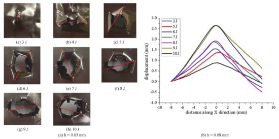
Figure 4.
(a) The morphologies of target material with different energies. (b) The outline of targets with different energies.
Table 3 shows the experimental results of Test 1 and Test 2, from which the relationship between the surface morphology change of the target and the laser pulse energy can be summarized. The laser impacted a TC4 titanium alloy target with a thickness of 0.08 mm, under the conditions of one impact time and a laser spot diameter of 7 mm, the plastic deformation degree of the target gradually grew with the upward trend in the energy of laser. When the laser energy is in a lower range, the percentage of its energy loss in the total energy decreases with the gradual growth of the laser pulse energy, and the effect of the laser-induced shock wave on the free surface of the target is more obvious. The maximum deformation was almost at the center of the laser impact, and as the distance from the center of the spot became larger, the deformation of the target material would be relatively reduced. When the thickness was 0.03 mm, the back of the target was not a smooth surface with varying degrees of deformation. The increase of laser energy resulted in larger and larger irregular holes. Holes came in diverse shapes, such as thin lines, windmills, petals and so on, and the measured aperture was positively correlated with the pulse energy of the laser.
Table 3.
Measurement of experimental data in Test 1 and Test 2.
The destruction of materials is a dynamic process that gradually accumulates: the formation of micro-cracks and micro-holes, the growth of cracks and holes, the growth of micro-cracks and micro-holes merges into large cracks and holes, large holes form one or multiple continuous fracture surfaces which penetrate the material, and the material fails and damages. When the laser spot diameter is 7 mm, the thickness of the titanium alloy target material is 0.03 mm. Because the target material is too thin, under the single pulse laser energy of 3 J to 10 J, the target material does not undergo the first three processes, and directly breaks under the laser shock. On the surface, failure damage occurs through the target material. For the titanium alloy target material with a thickness of 0.08 mm, under a single pulse laser energy of 3 J to 10 J, the target material shows a complete dynamic damage process, and finally it turns out to be deformed.
3.4. Influence of Shock Times on Forming Effect
The laser shock experiments on TC4 titanium alloy target with thickness of 0.08 mm were carried out under the following conditions: the laser energy was 6J, the spot diameter was 7 mm, and the impact time ranged from 1–7. The outline and morphologies of targets with different impact times are shown in Figure 5. Table 4 shows the changes in the target spalling deformation degree from 1 shock time to 7 shock times.
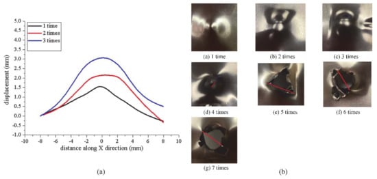
Figure 5.
(a) The outline of targets with different impact times. (b) The morphologies of target material with different impact times.
Table 4.
Measurement of experimental data of different impact times.
Figure 5 provides some interesting data regarding the maximum deformation of the target, and the graph also describes the trend of spallation degree. The nanosecond laser impacted a TC4 titanium alloy target with a thickness of 0.08 mm; under the conditions of 6 J laser pulse energy and a laser spot diameter of 7 mm, the plastic deformation degree of the target gradually increased with the upward trend in the number of impacts. This occurred until cracks were generated to finally penetrate the target material, forming holes with varying degrees of tearing. This experiment presents a complete fracture process of the titanium alloy target: during the first to the third impact, the target undergoes plastic deformation under laser loading, and micro-cracks and micro-holes are generated internally, and gradually expand and merge into larger cracks and holes. After the fourth laser impact, the combined cracks and holes form a continuous fracture surface and transition the entire material, after which the fracture surface continues to develop under constant laser loading, gradually forming petal-shaped holes. Therefore, in the laser shock processing of TC4 titanium alloy of this size, the appropriate number of laser pulse shocks should be selected according to the demand.
3.5. Resilience
It can be seen from Figure 3, when the thickness of the target was 0.08 mm, the spot diameter was 5 mm, the laser pulse energy was 10 J, and the pulse width was 10 ns, the back of the target appeared to exhibit the rebound phenomenon. The simulation results and experimental results under this impact condition are shown in Figure 6. At the end of the simulation process, the maximum shape variable of the target with this thickness was 0.582 mm, and the maximum limit of deformation was set to 0.590 mm in the software. As shown in Figure 6a, with the increase of the number of frames, the target deformation gradually increased from the maximum value of 0.590 mm to the maximum value of 0.655 mm. At this point, frames 77, 78 and 79 were all in the same state, and the displacement of the impact center of the target material was more than 0.590 mm and less than 0.655 mm. Figure 6b quantitatively verified the correctness of the above conclusion. As shown in the Figure 6b, when the number of frames was gradually increased from 66 to 100, the maximum displacements were 0.581 mm, 0.591 mm, 0.650 mm, 0.650 mm, 0.649 mm, 0.648 mm, 0.618 mm, 0.598 mm, 0.589 mm and 0.577 mm, respectively. After the shape variable reached the maximum value, it gradually decreased, forming a rebound. The laser-induced shock wave acts on the surface of the target material, which will be deformed under the influence of the shock wave pressure, and the deformation of the target material gradually increases over time. After the laser action, the shock wave pressure will gradually attenuate, and the target will continue to deform under the attenuated shock wave until the deformation reaches its maximum value, at which time the shock wave reaches the back of the target. When the laser energy and the thickness of the target material reach the corresponding conditions, under the action of the reverse stretching wave, the target material will go through a reverse deformation effect and the target material will rebound. Figure 6c is the surface topography of the target material after the experiment, and it can be clearly seen that the target material appears to rebound in the convex area.
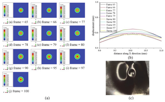
Figure 6.
(a) Displacement cloud map of target under different frames. (b) Target displacement curve under different frames. (c) The experimental result of the target.
4. Results of High-Speed Digital Camera
Dynamic monitoring experiments were applied by a high-speed digital camera to observe the entire laser shock experiment process and analyze the causes of various phenomena at different times, so as to effectively change the laser shock forming process and improve the quality of the impact forming.
The laser spot diameter of this experiment was 5 mm, and the target material with thickness from 0.01 mm to 0.08 mm used 4 J laser pulse energy. In order to better demonstrate the experimental results, 0.3 mm thickness of the target material used 10 J of laser energy. The experiments all chose a single pulse for impact. In Figure 7 and Figure 8, the changes in the morphology of the target back at different moments are displayed clearly, when the thickness of the target is 0.01 mm, 0.03 mm, 0.08 mm and 0.3 mm.
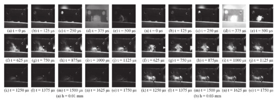
Figure 7.
(a) Changes in the morphology of the target back at different moments when h = 0.01 mm. (b) Changes in the morphology of the target back at different moments when h = 0.03 mm.
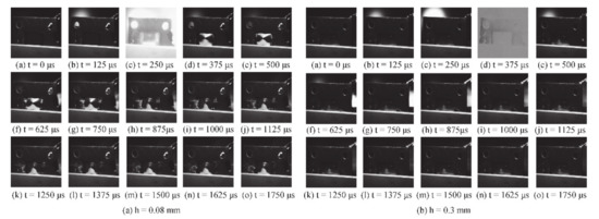
Figure 8.
(a) Changes in the morphology of the target back at different moments when h = 0.08 mm. (b) Changes in the morphology of the target back at different moments when h = 0.3 mm.
Owing to the choice of the experimental light source, the time interval of each frame of the picture under this experimental scheme was 125 μs. From Figure 7, it can be observed that there was white light not far from the target, and the brightness of the white light gradually increased with time, and finally the laser reached the front of the target. The plasma blast wave that expanded and burst was maintained by the laser energy and propagated into the target to form a shock wave [9]. In the experiment, it can be observed that the blast wave reached the back of the target. At this moment, a white bright area can be seen on the back of the target. Similar to the shape of the “mushroom cloud” produced by the explosion, it was guessed that this is the plasma of the expansion explosion. During the laser shock forming process, the laser irradiates the absorption layer on the surface of the target; then the absorption layer quickly absorbs the laser energy and vaporizes quickly. In the process of continuing to absorb the laser energy, the vapor is easily heated and ionized into plasma, and the plasma is directed to the target. The internal propagation forms a shock wave, and the shock wave acts on the surface of the material to cause plastic deformation. The next step was to find that under the action of the shock wave, the target was penetrated, and the water as the constrained overlay passed through the hole to reach the back of the target. The amount of water that passed through the hole increased as time passed. It is considered that there may still be some shock waves at this time; when it is observed that the amount of water passing through the hole gradually decreases and presents a fixed value, the change in the deformation of the target material is related to the impact of the water flow instead of continuing to deform under the action of the remaining shock wave.
The target material in Figure 8a underwent plastic deformation under the action of laser pulse energy but is not broken down by the laser. When t = 0 μs, no changes were found in the entire area. The phenomenon before the laser reached the front surface of the target was similar to the above results. When the laser reached the front surface of the target, it could be observed that with the generation of the plasma detonation wave, the white light intensity at the front surface of the target reached the maximum value. At the same time, plastic deformation could be seen behind the target and the conical appearance was found. The next step was to find that under the action of the residual shock wave, the plastic deformation degree of the target was slightly different from the previous step. With the increase of time, the plastic deformation of the target back did not change significantly, and the water flow did not affect the deformation of the target as in the previous two experiments.
As can be seen from Figure 8b, the graphs showed the changes in the morphology of the target at different times when the target thickness was 0.3 mm. The experimental results before 375 μs were similar to the above experiments. At 375 μs, it was found that the brightness of the white light generated by the plasma blast wave was too strong and the back surface of the target material under this experimental condition was not as obvious as the previous experimental results. Hence it was difficult to see the specific morphologies of the target material back at this moment. In the next step, it could be observed that there was a slight plastic deformation on the back of the target material, and no obvious change in the amount of deformation on the target back was observed with the naked eye after this moment. Due to the high cracking strength of TC4 titanium alloy material, the water flow acted as a constrained overlay and was not found to affect the deformation of the target.
5. Conclusions
Overall, the experimental results give a preliminary presentation of the forming criteria for titanium alloy sheets. During the laser loading process, the thickness of the target material, the diameter of the laser spot, the pulse energy and the number of impacts will all affect the forming effect of titanium sheet. It is concluded that the laser-induced plasma detonation wave impacts the material surface to achieve the purpose of plastic deformation. The plasma detonation wave was observed through a high-speed digital camera; meanwhile, the change of target morphology under the shock wave at different times could also be observed. The presented studies allow for a better basis for the future research on the role of the blast wave on the material.
The results provide evidence that the study of the forming criteria of titanium alloy material provides the basic data for laser processing of titanium alloy thin material in industrial production. In practice, the suitable laser parameters and target thickness can be selected according to the experimental results to optimize the laser impact forming effect. In the course of experiments, it is found that under the impact condition of 5 mm diameter and pulse energy of 10 J, the 0.08 mm thickness of TC4 titanium alloy target material will rebound; in order to obtain a better titanium alloy workpiece forming effect, the actual laser impact forming application process should avoid the rebound phenomenon. The research results not only provide a large amount of experimental data for laser processing of titanium alloy materials, but also improve the applicability of nano-laser in the impact forming of TC4 titanium alloy.
Author Contributions
Conceptualization, F.Y. and H.Y.; investigation, X.W.; resources, Y.T.; data curation, F.Y.; writing—original draft preparation, F.Y.; writing—review and editing, F.Y. and H.Y.; visualization, F.Y.; supervision, X.Y. and P.W.; funding acquisition, J.C. and H.Y. All authors have read and agreed to the published version of the manuscript.
Funding
This work has been supported by the National Natural Science Foundation of China (No. 51775253), the Fundamental Research Funds for the Central Universities (No. 2019B02614), China Postdoctoral Science Foundation (2017M611725).
Institutional Review Board Statement
Not applicable.
Informed Consent Statement
Not applicable.
Data Availability Statement
Data is contained within the article.
Conflicts of Interest
The authors declare no conflict of interest.
References
- Wang, Y.; Gan, F.; Fan, S.X. Theoretical analysis of impact force in laser impact molding. Laser J. 2013, 34, 54–56. [Google Scholar]
- Ji, K.K.; Zhang, X.Q.; Deng, L. Numerical Simulation on Deformation Velocity of 316L Stainless Steel Target Driven by Intense Lasers. Chin. J. Lasers 2016, 43, 110–117. [Google Scholar]
- Peyre, P.; Berthe, L.; Scherpereel, X. Laser-shock processing of aluminum-coated 55C1 steel in water-confinement regime, characterization and application to high-cycle fatigue behavior. J. Mater. Sci. 1998, 33, 1421–1429. [Google Scholar] [CrossRef]
- Tong, Y.Q.; Yao, H.B.; Zhang, Y.K. Experimental Research of High-Speed Plate Deformation Process Shocked by Strong and Short Pulsed Laser. Chin. J. Lasers 2011, 38, 122–126. [Google Scholar]
- Wu, J.; Zhou, J.Z.; Meng, X.K. Effect of laser shock strengthening on surface properties of W6Mo5Cr4V2 high speed steel. Surf. Technol. 2017, 46, 232–237. [Google Scholar]
- Ren, X.D.; Zhang, Y.K.; Zhou, J.Z.; Zhang, X.Q.; Lu, J.Z. Influence of laser parameters on laser shock forming of Ti6Al4V titanium alloy. Chin. J. Nonferrous Met. 2006, 16, 1850–1854. [Google Scholar]
- Cao, Z.W.; Zou, S.K.; Che, Z.G. Study on bending deformation and surface characteristics of aluminum alloy under laser-induced shock wave loading. Laser Optoelectron. Prog. 2015, 52, 130–134. [Google Scholar]
- Shi, C.Y. Study and Exploration on Fracture Criterion of Metal Sheet by Laser Shock Forming. Master’s Thesis, Jiangsu University, Zhenjiang, China, 2016. [Google Scholar]
- Zhang, Y. Numerical Simulation and Experimental Study of Laser Semi-Mode Multi-Point Shock Forming for Sheet Metal. Master’s Thesis, Anhui University of Technology, Ma on Shan, China, 2016. [Google Scholar]
- Xie, B.H. Study on Laser Shock Forming Process of Binary Optical Titanium Sheet. Master’s Thesis, Nanchang Hangkong University, Nanchang, China, 2016. [Google Scholar]
- Ren, X.D. High Temperature Service Material Laser Shock Technology; Science Press: Beijing, China, 2014; pp. 1–4. [Google Scholar]
- Fu, Y.; Liu, Q.; Ye, Y.; Hua, X.; Kang, Z.; Fu, H. Research on Laser Surface Micro Texturing Processing of Single Pulse Intervals. Chin. J. Lasers 2015, 42, 106–113. [Google Scholar]
- Gu, Y.Y.; Zhang, Y.K.; Zhang, X.Q. Theoretical study on the influence mechanism of confinement layer on shock wave pressure of laser drive. ACTA Phys. Sin. 2006, 11, 5885–5891. [Google Scholar]
- Zou, H.; Zhang, K.; Cao, X. Research of microstructure and residual stress of copper foils processed by laser shock forming. Laser Technol. 2018, 42, 94–99. [Google Scholar]
- William, B.; Robert, B. Finite element simulation of laser shock peening. Int. J. Fatigue 1999, 21, 719–724. [Google Scholar]
- Lian, Z.C. Numerical Study on Femtosecond Laser Shock Forming of Metallic Foil. Master’s Thesis, Jiangsu University, Zhenjiang, China, 2015. [Google Scholar]
- Johnson, G.R.; Cook, W.H. A constitutive model and data for metals subjected to large strains, high strain rates and high temperatures. In Proceedings of the Seventh International Symposium on Ballistics, Hague, The Netherlands, 19–21 April 1983. [Google Scholar]
- Fabbro, R.; Fournier, J.; Ballard, P. Physical study of laser-produced plasma in confined geometry. J. Appl. Phys. 1990, 74, 2268–2273. [Google Scholar] [CrossRef]
- Fan, N.; Yao, H.B.; Ye, X. Failure behavior of TC4 titanium alloy under strong laser loading. Laser Optoelectron. Prog. 2019, 56, 150–154. [Google Scholar]
- Yao, H.; Zhou, Z.; Xing, B.; Ding, G.; Tong, Y.; Ping, J.; Li, L.; Zhang, Y. Measurement of dynamic characteristics of metal sheet under laser shock. Chin. Opt. Lett. 2012, 10, 3201. [Google Scholar]
Publisher’s Note: MDPI stays neutral with regard to jurisdictional claims in published maps and institutional affiliations. |
© 2021 by the authors. Licensee MDPI, Basel, Switzerland. This article is an open access article distributed under the terms and conditions of the Creative Commons Attribution (CC BY) license (https://creativecommons.org/licenses/by/4.0/).