Article

Numerical Implementation of a Hydro-Mechanical Coupling Constitutive Model for Unsaturated Soil Considering the Effect of Micro-Pore Structure

1
Key Laboratory of Urban Underground Engineering of Ministry of Education, Beijing Jiaotong University, Beijing 100044, China
2
School of Civil Engineering, Beijing Jiaotong University, Beijing 100044, China
*
Author to whom correspondence should be addressed.
Appl. Sci. 2021, 11(12), 5368; https://doi.org/10.3390/app11125368
Submission received: 19 February 2021 / Revised: 18 April 2021 / Accepted: 26 April 2021 / Published: 9 June 2021
(This article belongs to the Section Mechanical Engineering)

Abstract

:
An unsaturated soil constitutive model considering the influence of microscopic pore structure can more accurately describe the hydraulic–mechanical behavior of unsaturated soil, but its numerical implementation is more complicated. Based on the fully implicit Euler backward integration algorithm, the ABAQUS software is used to develop the established hydro-mechanical coupling constitutive model for unsaturated soil, considering the influence of micro-pore structure, and a new User-defined Material Mechanical Behavior (UMAT) subroutine is established to realize the numerical application of the proposed model. The developed numerical program is used to simulate the drying/wetting cycle process of the standard triaxial specimen. The simulation results are basically consistent with those calculated by the Fortran program, which verifies the rationality of the developed numerical program.

1. Introduction

The hydro-mechanical coupling characteristics of unsaturated soils are closely related to many geotechnical engineering problems, such as the collapse of unsaturated soil slopes, the uneven settlement of unsaturated subgrade soil, and the movement of landfill leachate. Different from saturated soil, unsaturated soil is a three-phase mixture of solid, pore water and pore air, and its hydraulic–mechanical properties are complex. It is of great significance to establish a constitutive model to accurately describe the hydro-mechanical coupling characteristics of unsaturated soils.
Many scholars have conducted research on unsaturated hydro-mechanical coupling constitutive models and obtained valuable results: Wheeler et al. [1] found that the change in the degree of saturation S r will have an important effect on the unsaturated soil mechanical properties in the case of the same matric suction and mean net stress. At the same time, the effective stress p and modified suction s are used as stress variables, the conjugate variable volumetric strain ε v and the degree of saturation S r are used as strain variables, a coupled elastic–plastic model (the Glasgow coupled model, GCM) of the stress–strain behavior and liquid phase lag of unsaturated soil under isotropic stress state was proposed, and the coupling mechanism of the deformation characteristics and water retention characteristics was analyzed. Marti et al. [2] extended Wheeler’s model above to a three-dimensional stress state and elaborated several coupling mechanisms under a three-dimensional stress state. Sun et al. [3] established a three-dimensional unsaturated soil hydro-mechanical coupling elastoplastic model. This model considers the effect of suction on the hydraulic and mechanical properties of unsaturated soil, the influence of the S r on the stress–strain relationship and strength, and the effect of soil deformation on the soil–water characteristic curve (SWCC). Sheng et al. [4] first discussed coupled hydro-mechanical models from the perspective of thermodynamics and proposed a coupled hydro-mechanical model that can smoothly transition from an unsaturated state to a saturated state. In the framework of the constitutive model of continuous soil mechanics, Liu et al. [5] established an unsaturated hydro-mechanical coupling constitutive model: the generalized effective stress, modified suction and gas pressure are used as state variables. Zhou et al. [6] established a new unsaturated hydro-mechanical coupling constitutive model by using the degree of capillary saturation and the effective inter-particle stress. Li et al. [7] introduced the uploading surface to establish the hydro-mechanical coupling constitutive model of overconsolidated, unsaturated soil. Mahmoodabadi et al. [8] established an unsaturated hydro-mechanical coupling constitutive model by redefining the hysteresis and elastic shear strain components of the Sheng, Fredlund, Gens (SFG) model. Dat et al. [9] established a new unsaturated hydro-mechanical coupling constitutive model based on the generic thermodynamics.
Most of the existing constitutive models do not consider the influence of pore structure on the unsaturated soil’s hydro-mechanical coupling characteristics. Some scholars [10,11] found that the pore structure of unsaturated soil will change under loading or during a drying/wetting cycle, which is more obvious for soils with pore structures at two scales. Compared with intra-aggregate pores, the inter-aggregate pores in a soil with two pore structures are more sensitive to the interaction of water and force. Based on the GCM model proposed by Wheeler, a modified unsaturated hydro-mechanical coupling constitutive model, considering the influence of microscopic pore structure (the modified Glasgow coupled model, MGCM), was established for the isotropic state by Cai et al. [12]. In this model, the influence of macro- and micro-pores on the hydro-mechanical characteristics is considered by replacing S r with S e .
When using the constitutive model to solve the problem—that is, the boundary value problem—it is necessary to use a suitable integration algorithm to numerically implement the model at the Gaussian point scale. According to different integration modes, the integral algorithm of the unsaturated soil constitutive equation can be divided into implicit integrals and explicit integrals. The explicit constitutive integral algorithm adopts the forward Euler integral method to calculate the yield surface and the plastic potential gradient by using the stress at the starting point of each incremental step, which can be directly given by the constitutive matrix. Generally, an incremental step in the display algorithm will be divided into smaller substeps, and appropriate error control technology is used to ensure that the error is within the allowable range. Sheng et al. [13], Sánchez et al. [14], Sołowski et al. [15] and Zhou et al. [16] adopted an explicit algorithm to analyze constitutive models of unsaturated soil. For the implicit algorithm, the yield surface and plastic potential gradient are calculated by using the stress of the unknown stress point in the current step, and the constitutive matrix is also unknown. Therefore, numerical iteration is required to solve the constitutive equation. The implicit algorithm has a faster convergence speed and produces a more accurate calculation than an explicit algorithm. Zhang et al. [17,18], Hoyos et al. [19], Liu et al. [20], Sołowski et al. [21], Enrico [22], Barbara [23] and Ma [24] adopted an implicit algorithm to analyze unsaturated soil. Hu et al. [25] and Sołowski et al. [26] used the two algorithms mentioned above to numerically implement a constitutive model of unsaturated soil and then compared and analyzed the performance of the two algorithms. At present, there are few reports on the numerical implementation of the constitutive model, considering the influence of the unsaturated soils’ micro-pore structure. Considering the influence of the micro-pore structure of unsaturated soils is of great significance for improving the accuracy of the numerical analysis of related engineering problems.
In this paper, the established MGCM [8] is summarized first. Then, based on Euler’s backward implicit integration algorithm, the Fortran calculation program of the proposed model is imported into ABAQUS for secondary development. The numerical application of the model is implemented. The developed numerical program is used to simulate the wetting–drying–wetting paths test of a triaxial sample, and the rationality of the developed numerical program is verified by comparison with the calculation results of the Fortran program.

2. Modified Glasgow Coupled Model (MGCM) Overview

Considering the interaction between the changes in the microscopic pore structure and the soil behavior of unsaturated soil with two pore structures, Cai. et al. [12] introduced the S e into the p in the GCM. Cai et al. established an unsaturated hydro-mechanical coupling constitutive model considering the influence of microscopic pore structure for an isotropic stress state and extended the model to the three-dimensional stress space. The model is described as follows.

2.1. Effective Degree of Saturation Considering the Influence of the Microscopic Pore Structure

The S e can be defined as follows to consider the effect of the microscopic pore structure [27]:
S e = S r S r m 1 S r m = S r S res 1 S res
where S r m is the S r of the intra-aggregate pores, which is numerically equal to the residual degree of saturation S res of the unsaturated soil. The S e essentially reflects the degree to which the macropores are filled by water, and its value range is (0,1). For a soil with a single pore structure, there is no difference in the saturations between the large and small pores—that is, S r m = 0 , S e = S r m . For soil with two pore structures, the pores at each scale account for a certain proportion of the total pore volume. With the increase in clay content, the degree of micro-pore saturation increases gradually, the large pores are gradually replaced by small ones, and the saturation limit is reached. At this time, S r m = S r , S e = 0 .
Using the S e instead of the S r to establish the model can distinguish the contribution of different types of pores to the soil deformation.

2.2. Constitutive Variables
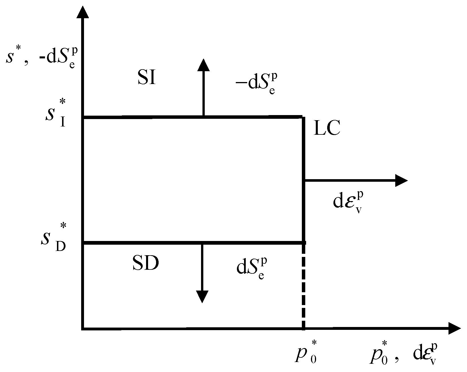
Based on the energy equation, taking into account the conjugation of the stress and strain variables into energy, the effective stress [28] p considering the micro-pores and the modified suction s are used as the two stress variables:
p = p ¯ + S e s = ( p u a ) + S e ( u a u w )
s = n s = n ( u a u w )
where p ¯ is the mean net stress, p is the total stress, s is the matric suction, and n is the porosity. Regardless of whether the suction is zero, as long as the sample is saturated, p can always return to the effective stress expression of the saturated soil.
From Equations (2) and (3), the stress variable increments can be obtained as follows:
d p = d p ¯ + S e d s + s d S e
d s * = n d s + s ( n 1 ) d ε v
where d ε v and d S e are the conjugate strain increments corresponding to the p and s , respectively.

2.3. Yield Curves

The LC, SI and SD yield curves for isotropic stress states are considered approximately straight lines, as shown in Figure 1. LC is the loading collapse yield curve in p * s * plane, SI is the suction increase yield curve and SD is the suction decrease yield curve. Only elastic strains occur in the rectangular region enclosed by the three yield curves.
The LC, SI and SD yield curve equations are given as follows:
p = p 0
s = s I *
s = s D *
where p 0 , s I * and s D * are hardening parameters, which define the current locations of the LC, SI and SD yield curves.

2.4. Hardening Law

Under hydro-mechanical coupling, the evolution law of each yield curve—namely, the hardening law—can be obtained through the interaction of solid and liquid phases. Assume that the coupling mechanism can be expressed as the following three cases.
Plastic volumetric strain occurs only when the stress point reaches the LC yield curve, causing the coupling of the SI and SD curves to move up. k 2 is the coupling parameter, and the coupled movements equations of the SI and SD yield curves are given as follows:
d s Ι / D s Ι / D = k 2 d p 0 p 0
The plastic S r decreases when the stress point reaches the SI yield curve, causing the coupling of the SD curve to move up and the LC curve to move out. The plastic S r increases when the stress point reaches the SD yield curve, causing the coupling of the SI curve to move down and the LC curve to move in. k 1 is the second coupling parameter. The coupling relationship can be given by:
d p 0 p 0 = k 1 d s I s I   a n d   d p 0 p 0 = k 1 d s D s D
In general, the movement of the LC yield curve is determined by its own direct movement and the coupled movement of the SI or SD curves. The hardening equation of the solid phase is given by:
d p 0 p 0 = ν d ε v p ( λ κ ) k 1 d S e p ( λ w κ w )
where λ is the saturated normal compression line slope and λ w is the SWCC boundary line slope. κ is the saturated elastic swelling line slope in the ν ln p * plane. κ w is the slope of the scanning line of the SWCC. d ε v p is the incremental form of the plastic volumetric strain, and d S e p is the incremental form of the plastic effective degree of saturation.
Similarly, the liquid phase hardening equation is given by:
d s I / D s I / D = d S e p ( λ w κ w ) + k 2 ν d ε v p ( λ κ )

2.5. Flow Rule

One or more plastic mechanisms are activated during the yield process. The flow rule for the LC, SD and SI yield curves corresponds to the associated flow rule. We assume that only plastic volumetric strain occurs when yielding on the LC yield curve but causes no changes in the S e p .
d S e p d ε v p = 0
Similarly, we assume that only plastic S e p occurs when yielding on the SI or SD yield curves but causes no changes in the plastic volumetric strain. The associated flow rule applied on the SD or SI yield curve is given as follows:
d ε v p d S e p = 0

2.6. Stress–Strain Relationship

The incremental expressions of the elastic strain are as follows:
d ε v e = κ ν d p p
where ν is the specific volume:
d S e e = κ w d s s
According to the solid-phase hardening equation and liquid-phase hardening equation defined in the MGCM, the plastic strain increment relationship of unsaturated soil can be derived:
d ε v p = ( λ κ ) ν ( 1 k 1 k 2 ) ( d p 0 p 0 k 1 d s I / D s I / D )
d S e p = ( λ w κ w ) ( 1 k 1 k 2 ) ( d s I / D s I / D + k 2 d p 0 p 0 )
The total strain increment equation is as follows:
d ε v = d ε v e + d ε v p = κ ν d p 0 p 0 + ( λ κ ) ν ( 1 k 1 k 2 ) ( d p 0 p 0 k 1 d s I / D s I / D )
d S e = d S e e + d S e p = κ w d s I / D s I / D + ( λ w κ w ) ( 1 k 1 k 2 ) ( d s I / D s I / D + k 2 d p 0 p 0 )

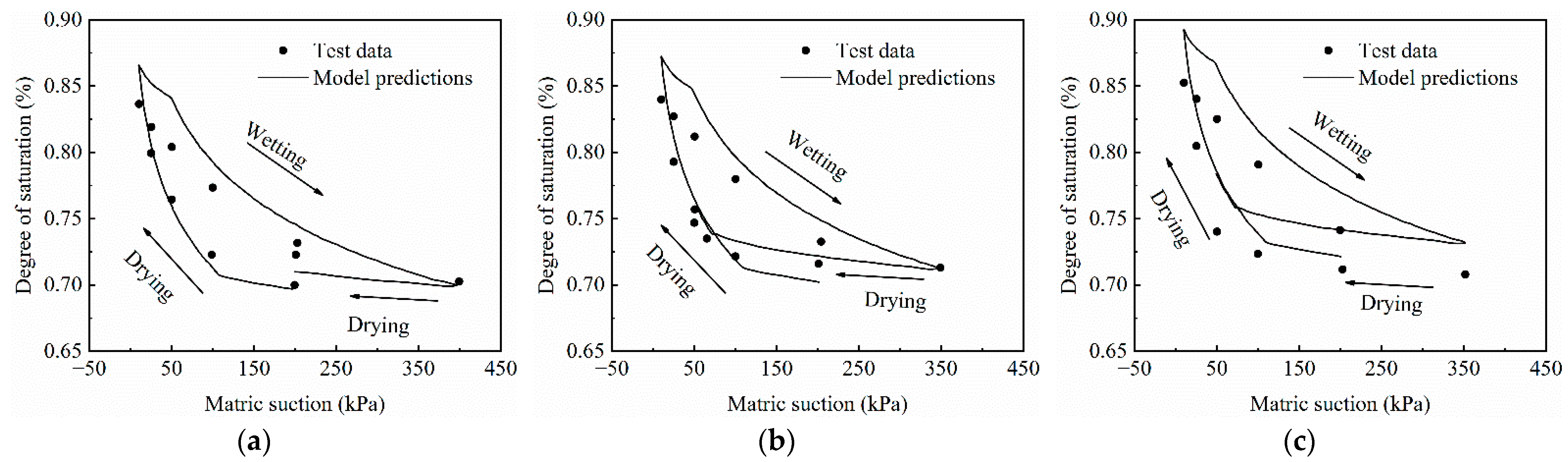
3. Fortran Program Prediction and Validation

Cai et al. have verified the predictive ability of the model under isotropic compression conditions, and the predictive ability of the proposed model during a drying–wetting cycle will be verified in this paper. Chen [29] carried out a number of constant mean net stress drying–wetting tests of Wuhan Zaoyang expansive soil by using a computer-controlled triaxial stress-path testing system inherited from Zhan [30]. The triaxial cell is a Bishop and Wesley stress-path cell for testing up to 100 mm diameter cylindrical specimen. The change in suction is achieved by varying pore water pressure. Three sets of drying–wetting test data were selected for model validation. For test A, the constant mean net stress is p ¯ = 40   kPa , and the suction path of the sample is 200 kPa→10 kPa→400 kPa→200 kPa. For test B, the constant mean net stress is p ¯ = 70   kPa , and the suction path of the sample is 200 kPa→10 kPa→350 kPa→50 kPa. For test C, the constant mean net stress is p ¯ = 100   kPa , and the suction path of the sample is 200 kPa→10 kPa→350 kPa→50 kPa. The model parameters of Zaoyang expansive soil and the initial state parameters of the three sets of tests are listed in Table 1 and Table 2.
Figure 2 shows the comparison between the model predictions and the test data. The proposed model can reasonably predict the hydro-mechanical coupling characteristics of unsaturated soils for drying–wetting cycles. The specific volume of the soil gradually increases due to the decrease in the p * in the soil during the wetting process, which results in elastic expansion deformation. However, the modified suction in the soil decreases, which results in yielding on the SD and causes the LC curve to move inward. The S r increase rate increases. The modified suction in the soil changes without yielding on the SI curve during the drying process. The S r change is elastic. The effective stress of the soil increases, and yielding occurs on the LC curve. The change rule of the specific volume during drying is more complex and different from that during wetting. The proposed model can reflect not only the influence of the liquid deformation on the soil skeleton deformation but also the influence of the soil deformation on the SWCC.

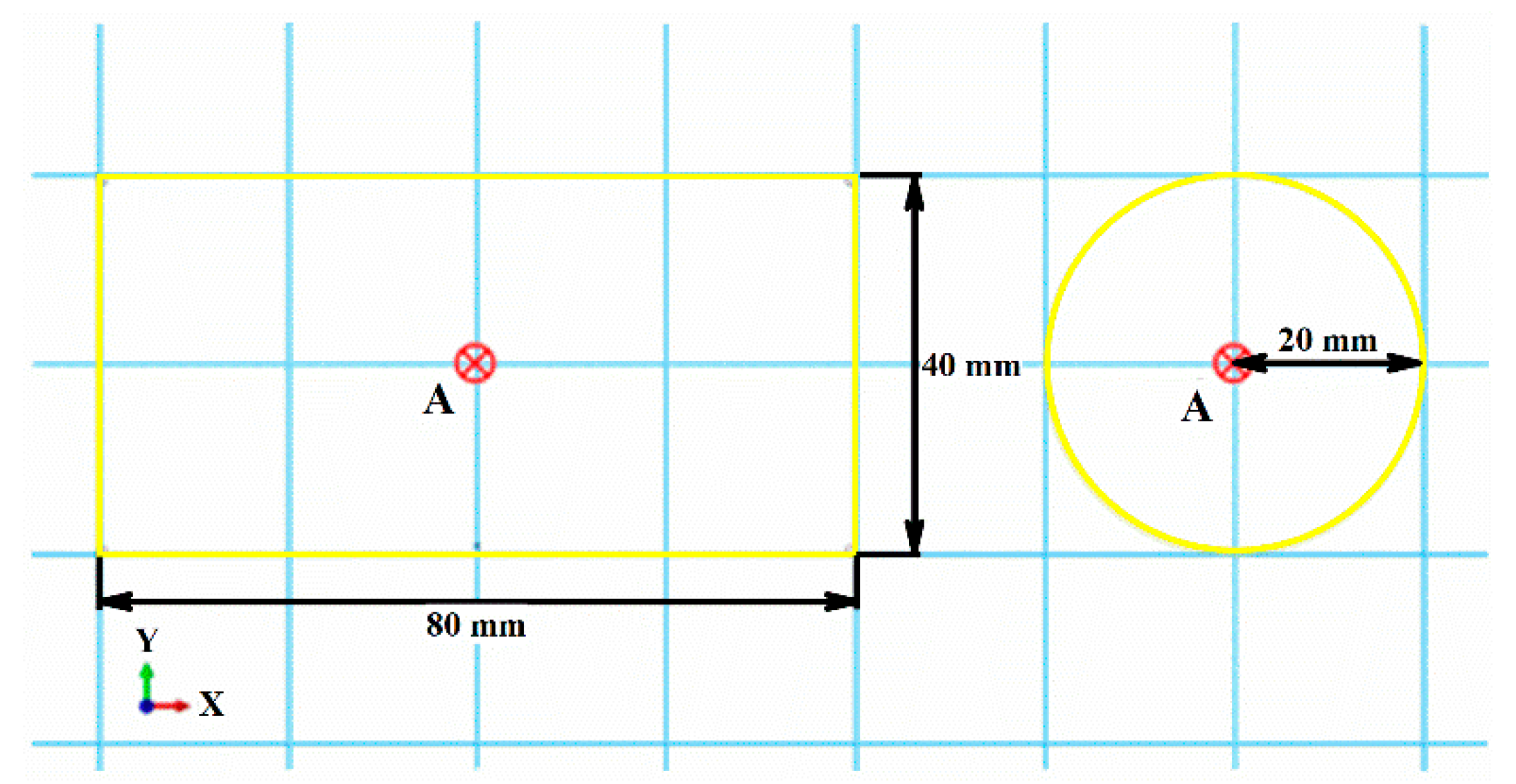
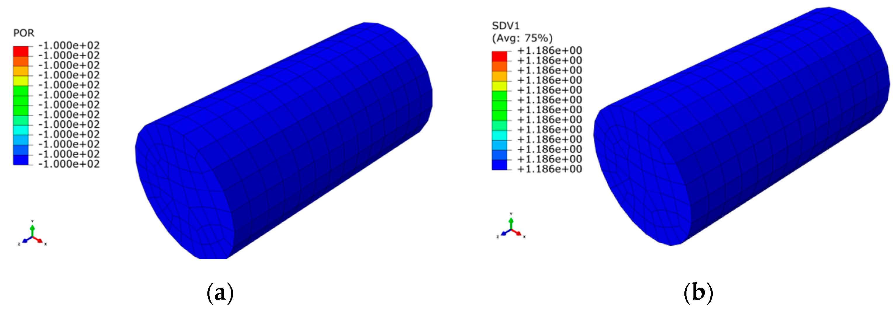
4. Numerical Implementation

4.1. Solid-Phase and Liquid-Phase Yield Equations

To develop the UMAT subroutine, the stress state of unsaturated soil must be considered. Under natural conditions, most soils will be subjected to effective or net stress, so it is necessary to define a solid-phase yield equation in the p * q stress plane. In this paper, the modified Cambridge Clay model [31] is defined as the yield equation:
F LC = q 2 M 2 p ( p 0 p ) = 0
where q is the deviator stress, and M is the critical state line slope.
This paper mainly considers the soil deformation behavior caused by water–force coupling during wetting–drying processes, so it is also necessary to define a liquid-phase yield equation in the p * s * stress space. In this paper, Equation (8) is used to defined the yield equation:
F SD = s D s = 0

4.2. Matrix Form Stress–Strain Relation

To better realize secondary development in the ABAQUS finite element platform, the modified suction is regarded as a stress component, and the S e is regarded as a strain component. Three positive stress components, three shear components and the modified suction component are combined into a 1 × 7 generalized stress vector. Three positive strain components, three shear components and the effective degree of saturation component are combined to form a 1 × 7 generalized strain vector. Therefore, the stress and strain tensors are given as the following vectors:
σ ˜ * = ( σ 11 , σ 22 , σ 33 , τ 12 , τ 13 , τ 23 , s ) T
ε ˜ = ( ε 11 , ε 22 , ε 33 , γ 12 , γ 13 , γ 23 , S e ) T
The incremental expression of the stress–strain relationship is given by:
d σ ˜ * = D e * d ε ˜ e = D e * ( d ε ˜ d ε ˜ e ) = D e p * d ε ˜
where d σ ˜ * is the increment form of the stress vector, D e * is the 7 × 7 generalized elastic matrix, d ε ˜ e is the increment form of the elastic strain vector, d ε ˜ is the increment form of the total strain vector, and D e p * is the 7 × 7 elastic–plastic matrix. The D e p * form is determined by the plastic mechanism of the loading process. The plasticity mechanism is divided into yielding on LC only, yielding on SI/SD only and yielding on LC and SI/SD at the same time.

4.3. Implicit Integration Algorithm

In each iteration, after obtaining the displacement increment Δ u , suction increment Δ s and degree of saturation increment Δ S r , the steps to determine the new stress state are as follows.
(1) Elastic trial calculation
The geometric equation is used to calculate the increment of the solid deformation, and the trial value of the stress is calculated according to the pure elastic stress–strain relationship.
{ [ Δ ε ] = [ B ] [ Δ u ] [ Δ σ ˜ e ] = [ D e ] [ Δ ε ˜ ] [ σ ˜ ] t + Δ t = [ σ ˜ ] t + [ Δ σ ˜ e ]
where [ Δ σ ˜ ] t + Δ t is the stress value at the end of the last iteration step.
(2) Yield determination
According to the stress test value, the yield function value is calculated: f ( [ σ ˜ ] t + Δ t ) . If f ( [ σ ˜ ] t + Δ t ) 0 , the Gaussian point will maintain the elastic state under the obtained strain increment; if f ( [ σ ˜ ] t + Δ t ) > 0 and f ( [ σ ˜ ] t ) < 0 , the Gaussian point will change from the elastic state to the plastic state under the obtained strain increment.
(3) Plasticity correction
If f ( [ σ ˜ ] t + Δ t ) 0 , then [ Δ σ ˜ ] = [ Δ σ ˜ e ] , and no plastic correction is needed; if f ( [ σ ˜ ] t + Δ t ) > 0 and f ( [ σ ˜ ] t ) < 0 , the test stress value is outside the yield surface, and this state is not allowed. A stress value outside the yield surface should be corrected to coincide with the yield surface. According to the actual yield situation, the plasticity correction should be carried out using Equation (18).

5. Model Validation

In this section, we use the UMAT subroutine of the MGCM to simulate drying–wetting cycle tests of unsaturated soil triaxial samples for the model verification. By comparing the pore water pressure and void ratio changes in the simulation process with the prediction results of the Fortran program, the practicability of the UMAT subroutine is verified.
The sample is a triaxial sample with a diameter of 40 mm and a height of 80 mm. The cell type is selected as a three-dimensional pore water pressure element with 8 nodes (C3D8P). Figure 3 shows a schematic diagram of the triaxial sample model. The sample material parameters are as follows: λ = 0.11 , κ = 0.02 , λ w = 0.125 , κ w = 0.063 , k 1 = 0.012 , k 2 = 1.8 , M = 1.2 . The initial hardening parameter of effective stress is p 0 = 200   kPa , and the permeability coefficient of the sample model is 3.6 × 10⁻⁵ m/s. In this experiment, we set the displacement boundary condition at the initial analysis step to constrain the axial degree of freedom of the bottom surface. The pore water pressure boundary condition is set to a uniform pore water pressure of −100 kPa, and its corresponding S r is 0.1. The e 0 is 1.186, the three initial normal stresses are −100 kPa, and the three initial shear stresses are zero (tension is positive in ABAQUS). In the consolidation analysis step, an equivalent pressure load of 100 kPa is set to balance the initial stress. During the drying–wetting cycle, a negative pore water pressure (matric suction) is applied on the top of the sample by using the Amplitude function in ABAQUS. The distribution laws of the pore water pressure and void ratio in the initial equilibrium state, wetting process and drying process are shown in Figure 4, Figure 5 and Figure 6.
The initial equilibrium process of the sample model is similar to the triaxial consolidation process of triaxial samples of the same size under 100 kPa of confining pressure. According to the pore water pressure distribution result and void ratio distribution obtained in the equilibrium analysis step, the applied pressure boundary, displacement boundary, pore water pressure boundary and initial stress are well balanced. During the wetting process, the pore water pressure gradually decreases from the bottom of the sample model upward, and the S r also decreases. At the same time, due to wetting, the matric suction inside the sample model gradually decreases, which causes the effective stress to decrease, so the specific volume of the sample model also increases. During the drying process, the pore water pressure gradually increases from the bottom of the sample model upward, and the S r also increases. At the same time, due to drying, the internal matric suction of the sample model gradually increases, which causes the effective stress to increase, so the specific volume of the sample model continues to decrease.
The relationship between the void ratio and matric suction during the drying–wetting cycle is shown in Figure 7. A comparison between the UMAT subroutine and the Fortran program calculation results is also shown. The calculation results of the UMAT subroutine and Fortran program are basically the same: the sample model produces elastic expansion deformation during the wetting process, and drying process causes the plastic deformation. Therefore, the UMAT subroutine can accurately simulate the unsaturated soil hydro-mechanical coupling characteristics during a drying–wetting cycle.

6. Conclusions

In this article, we summarize the established unsaturated hydro-mechanical coupling model considering the effect of microscopic pore structure and the drying–wetting test data are used for the model verification. Based on Euler’s backward implicit integration algorithm, the Fortran program of the model is imported into ABAQUS to create a UMAT subroutine for secondary development to realize the application of the model. The drying–wetting cycle test of a triaxial sample model is used to demonstrate the simulation performance of the developed numerical program. The results indicate that the developed program can reasonably describe the distribution of pore water pressure and void ratio during the wetting–drying process of a sample model. The prediction results of matric suction and void ratio during the drying–wetting process from the developed program are basically consistent with the prediction results from the Fortran program, indicating that the developed program can effectively describe the unsaturated soil hydro-mechanical coupling characteristics during a drying–wetting cycle.

Author Contributions

Data curation, B.H. and K.D.; Formal analysis, K.D. and J.L.; Funding acquisition, G.C.; Investigation, B.H. and Y.L.; Software, K.D.; Validation, K.D. and T.W.; Writing—original draft, M.L.; Writing—review and editing, B.H. All authors have read and agreed to the published version of the manuscript.

Funding

This research was financially supported by the Fundamental Research Funds for the Central Universities (2020CZ002), the National Natural Science Foundation of China (51722802, 51678041, U1834206), Beijing Natural Science Foundation (8202038) and Beijing Nova Program (Z181100006218005).

Institutional Review Board Statement

Not Applicable.

Informed Consent Statement

Not Applicable.

Data Availability Statement

Not Applicable.

Conflicts of Interest

The authors declare no conflict of interest.

References

  1. Wheeler, S.J.; Sharma, R.S.; Buisson, M.S.R. Coupling of hydraulic hysteresis and stress-strain behaviour in unsaturated soils. Géotechnique 2003, 53, 41–54. [Google Scholar] [CrossRef]
  2. Marti, L.C.; Sanchez, M.; Wheeler, S.J. Formulation of a three-dimensional constitutive model for unsaturated soils incorporating mechanical-water retention couplings. Int. J. Numer. Anal. Met. 2013, 37, 3008–3035. [Google Scholar] [CrossRef]
  3. Sun, D.A.; Sheng, D.C.; Sloan, S.W. Elastoplastic modelling of hydraulic and stress-strain behaviour of unsaturated compacted soils. Mech. Mater. 2007, 39, 212–221. [Google Scholar] [CrossRef]
  4. Sheng, D.C.; Sloan, S.W.; Gens, A. A constitutive model for unsaturated soils: Thermo-mechanical and computational aspects. Comput. Mech. 2004, 33, 453–465. [Google Scholar] [CrossRef]
  5. Liu, Y.; Zhao, C.G.; Cai, G.Q.; Huang, L. Constitutive modeling for unsaturated soils considering gas hardening effect. Chin. Sci. Bull. 2011, 56, 1739–1745. [Google Scholar] [CrossRef] [Green Version]
  6. Li, W.G.; Yang, Q. Hydromechanical constitutive model for unsaturated soils with different overconsolidation ratios. Int. J. Geomech. 2018, 18, 04017142. [Google Scholar] [CrossRef]
  7. Zhou, A.N.; Wu, S.S.; Li, J.; Sheng, D.C. Including degree of capillary saturation into constitutive modelling of unsaturated soils—ScienceDirect. Comput. Geotech. 2018, 95, 82–98. [Google Scholar] [CrossRef]
  8. Mahmoodabadi, M.; Bryson, L.S. Constitutive Model for describing the fully coupled hydromechanical behavior of unsaturated soils. Int. J. Geomech. 2021, 21, 04021027. [Google Scholar] [CrossRef]
  9. Dat, G.P.; Giang, D.N.; Ha, H.B.; Terry, B. Constitutive modelling of partially saturated soils: Hydro-mechanical coupling in a generic thermodynamics-based formulation. Int. J. Plast. 2021, 136, 102821. [Google Scholar]
  10. Alonso, E.E.; Romero, E.; Hoffmann, C. Hydromechanical behaviour of compacted granular expansive mixtures: Experimental and constitutive study. Géotechnique 2011, 61, 329–344. [Google Scholar] [CrossRef]
  11. Nowamooz, H.; Masrouri, F. Suction variations and soil fabric of swelling compacted soils. J. Rock. Mech. Geotech. 2010, 2, 129–134. [Google Scholar] [CrossRef] [Green Version]
  12. Cai, G.Q.; Wang, Y.N.; Zhou, A.N.; Zhao, C.G. A microstructure-dependent hydro-mechanical coupled constitutive model for unsaturated soils. Chin. J. Geotech. 2018, 40, 618–624. [Google Scholar]
  13. Sheng, D.C.; Sloan, S.W.; Gens, A.; Smith, D.W. Finite element formulation and algorithms for unsaturated soils. Part I: Theory. Int. J. Numer. Anal. Met. 2003, 27, 745–765. [Google Scholar] [CrossRef]
  14. Sánchez, M.; Gens, A.; Guimarães, L.; Olivella, S. Implementation algorithm of a generalised plasticity model for swelling clays. Comput. Geotech. 2008, 35, 860–871. [Google Scholar] [CrossRef]
  15. Sołowski, W.T.; Gallipoli, D. Explicit stress integration with error control for the Barcelona basic model. Part I: Algorithms formulation. Comput. Geotech. 2010, 37, 59–67. [Google Scholar] [CrossRef]
  16. Zhang, H.W.; Heeres, O.M.; Borst, R.D. Implicit integration of a generalized plasticity constitutive model for partially saturated soil. Eng. Comput. 2001, 18, 314–336. [Google Scholar] [CrossRef]
  17. Zhang, H.W.; Zhou, L. Implicit integration of a chemo-plastic constitutive model for partially saturated soils. Int. J. Numer. Anal. Met. 2008, 32, 1715–1735. [Google Scholar] [CrossRef]
  18. Hoyos, L.R.; Arduino, P. Implicit algorithms in modeling unsaturated soil response in three-invariant stress space. Int. J. Geomech. 2008, 8, 266–273. [Google Scholar] [CrossRef]
  19. Liu, C.Y.; Muraleetharan, K.K. Coupled hydro-mechanical elastoplastic constitutive model for unsaturated sands and silts. II: Integration, calibration, and validation. Int. J. Geomech. 2012, 12, 248–259. [Google Scholar] [CrossRef]
  20. Solowski, W.T.; Gallipoli, D. A stress-strain integration algorithm for unsaturated soil elasto-plasticity with automatic error control. In Numerical Methods in Geotechnical Engineering-Proceedings of the 6th European Conference on Numerical Methods in Geotechnical Engineering; Taylor and Francis Group: Graz, Austria, 2006; pp. 113–119. [Google Scholar]
  21. Zhang, Y.; Zhou, A.N.; Nazem, M.; Carter, J. Finite element implementation of a fully coupled hydro-mechanical model and unsaturated soil analysis under hydraulic and mechanical loads. Comput. Geotech. 2019, 110, 222–241. [Google Scholar] [CrossRef]
  22. Enrico, S. Experimental and Numerical Investigations of face Stability of Shallow Tunnels in Partially Saturated Soil. Ph.D. Thesis, University of Natural Resources and Life Sciences, Vienna, Austria, 2014. [Google Scholar]
  23. Barbara, M.S. Analysis of Slope Stabilization by Soil Bioengineering Methods. Ph.D. Thesis, University of Natural Resources and Life Sciences, Vienna, Austria, 2016. [Google Scholar]
  24. Ma, T.T.; Wei, C.F.; Chen, P.; Wei, H.Z. Implicit scheme for integrating constitutive model of unsaturated soils with coupling hydraulic and mechanical behavior. Appl. Math. Mech. 2014, 35, 1129–1154. [Google Scholar] [CrossRef]
  25. Hu, C.; Liu, H.X. Implicit and explicit integration schemes in the anisotropic bounding surface plasticity model for cyclic behaviours of saturated clay. Comput. Geotech. 2014, 55, 27–41. [Google Scholar] [CrossRef] [Green Version]
  26. Sołowski, W.T.; Hofmann, M.; Hofstetter, G.; Sheng, D.C.; Sloan, S.W. A comparative study of stress integration methods for the Barcelona Basic Model. Comput. Geotech. 2012, 44, 22–33. [Google Scholar] [CrossRef]
  27. Alonso, E.E.; Pereira, J.M.; Vaunat, J.; Olivella, S. A microstructurally based effective stress for unsaturated soils. Géotechnique 2010, 60, 913–925. [Google Scholar] [CrossRef] [Green Version]
  28. Bishop, A.W. The principle of effective stress. Tek. Ukebl. 1959, 106, 859–863. [Google Scholar]
  29. Chen, R. Experimental Study and Constitutive Modelling of Stress-Dependent Coupled Hydraulic Hysteresis and Mechanical Behaviour of an Unsaturated Soil. Ph.D. Thesis, The Hong Kong University of Science and Technology, Kowloon, Hong Kong, 2003. [Google Scholar]
  30. Zhan, L.T. Field and Laboratory Study of an Unsaturated Expansive Soil Associated with Rain-Induced Slope Instability. Ph.D. Thesis, the Hong Kong University of Science and Technology, Kowloon, Hong Kong, 2003. [Google Scholar]
  31. Roscoe, K.H.; Burland, J.B. On the generalized stress-strain behaviour of wet clay. Eng. Plast. 1968, 3, 539–609. [Google Scholar]
Figure 1. Yield curves for isotropic stress states.
Applsci 11 05368 g001
Figure 2. Comparison between model predictions and test data: (a) Test A; (b) Test B; (c) Test C.
Applsci 11 05368 g002
Figure 3. Triaxial sample model.
Applsci 11 05368 g003
Figure 4. Distributions of the pore water pressure and void ratio in the initial equilibrium state: (a) Pore water pressure distribution; (b) Void ratio distribution.
Applsci 11 05368 g004
Figure 5. Distributions of the pore water pressure and void ratio during the wetting process: (a) Pore water pressure distribution; (b) Void ratio distribution.
Applsci 11 05368 g005
Figure 6. Distributions of the pore water pressure and void ratio during the drying process: (a) Pore water pressure distribution; (b) Void ratio distribution.
Applsci 11 05368 g006
Figure 7. Comparison between the predictions of the UMAT subroutine and Fortran program.
Applsci 11 05368 g007
Table 1. Model parameters for Zaoyang expansive clay.
λ κ λ s κ s k 1 k 2 M μ
0.110.020.080.020.40.90.870.3
Table 2. Initial state for different samples of Zaoyang expansive clay.
Number λ SrSres S D * /KPa S I * /KPa p 0 * /KPa
A1.7130.6900.1545.7228.6430
B1.7180.681
C1.7150.688
Publisher’s Note: MDPI stays neutral with regard to jurisdictional claims in published maps and institutional affiliations.

