Featured Application
Development of novel microprocessor-controlled prosthetic knee.
Abstract
The key technology of the prosthetic knee is to simulate the torque and angle of the biological knee. In this work, we proposed a novel prosthetic knee operated in semi-active mode. The structure with ball-screw driven by the motor and the passive hydraulic damping cylinder was presented. A four-bar linkage was adapted to track the instantaneous center motion of human knee. The mathematical models of hydraulic cylinder damping and active torque were established to simulate the knee torque and angle. The results show that the knee torque symmetry index is smaller than 10% in the whole gait. The knee angle symmetry index value is 34.7% in stance phase and 11.5% in swing phase. The angle in swing phase is closer to the intact knee. The semi-active prosthetic knee could provide similar torque and angle of the biological knee in the simulation. It has shown good potential in improving the gait symmetry of the transfemoral amputee.
1. Introduction
Thousands of people lose their lower limbs due to circulatory and vascular problems, diabetes complications, cancer, or trauma every year. Among them, some people lost part or all of their lower limbs and the ability to walk need to be restored by lower limb prosthesis []. Transfemoral amputees often face more difficulty in the walking ability reconstruction since both the knee and ankle joints are lost. The prosthetic knee is the most important joint components of the lower limb prosthesis for transfemoral amputee [].
The gait parameters are important for the safe design of prosthetics and orthotics [,]. The transfemoral amputees often more relied on intact side due to the distrust of prosthetic limb. The daily ambulation requires the prosthetic knee to accommodate for force, speed, or terrain alterations. The limited and abnormal gait, decreased safety, and higher energy expenditure were observed of transfemoral amputees. The performance of the prosthetic knee decides the life quality of the transfemoral amputee.
The prosthetic knee can be divided into three categories according to structures and knee torque realization methods. They are mechanical passive, variable damping, and dynamic active prosthesis []. The performance of conventional mechanical passive knee joints is limited due to the lack of sensing and driving. Transfemoral amputees often have asymmetrical gait and have to walk more slowly than able-bodied people. This leads to more metabolic energy being consumed [].
The major commercial microprocessor-controlled prosthetic knees are variable damping. The typical damping types are pneumatic, hydraulic, and magnetorheological []. Chin et al. conducted a comparative study of energy expenditure and walking speeds between able-bodied people and young users of pneumatic Intelligent Prosthesis (IP). This study showed that the pneumatic IP could improve the walking performance of the users. However, the pneumatic IP just had electronic control of the swing phase and the energy expenditure of users increased by 24% compared to able-bodied people []. Lura et al. determined the differences in knee flexion between the Genium and C-Leg microprocessor-controlled hydraulic knees while walking on level ground and ramps []. The Genium and C-Leg are able to electronically control the hydraulic damping in both swing and stance phase. However, they still could not provide active torque during upstairs or stance extension. Bellmann et al. conducted comparative biomechanical evaluation of Rheo Knee with magnetorheological damper and C-Leg []. Although the passive variable damping prosthetic knees have advantages in weight and clinical application, the common defect of variable damping prosthetic knees is difficult to extend the leg during active knee torque phase due to its lack of any active actuator. Their performance is difficult to improve during stair ascent or upslope because of the lack of active knee torque [].
Many researchers have focused on the research of active prosthesis which can inject power to the knee joint. A powered knee-ankle prosthesis was developed by the team of Vanderbilt University. The motor and ball-screw were adapted to transmit the active torque [,]. Elery et al. presented the design of a powered knee-ankle prosthetic leg, which implements high-torque actuators with low-reduction transmissions []. Mendez et al. presented a powered knee and ankle prosthesis with indirect volitional swing control enables level-ground walking and crossing over obstacles []. However, the powered prosthesis is often heavy and consumes significant energy []. The weight of active knee-ankle prostheses is still over the clinically acceptable level due to the large motor and heavy transmission mechanism.
Compared with the mechanical passive knee joint, the variable damping prosthetic knee has the advantages of providing different damping torque, enhancing the stability, adapting to environmental changes, and the walking speed adaption []. It improves gait symmetry and reduces musculoskeletal degeneration of transfemoral amputees to a degree []. The power prosthetic knee enables amputees to perform activities such as walking up stairs and standing from a sitting position. However, the active prosthetic knee is energy-intensive and requires a large actuator, which increases the weight of the prosthetic knee and reduces the battery life. The biological knee provides active and passive torque during walking []. Active or passive microprocessor-controlled prosthetic knees cannot simulate the hybrid work mode. The prosthetic knee with active-passive control is a solution to solve the problem. Thus, the prosthetic knee combines the advantages of powered and variable damping prosthetic knees—namely semi-active prosthetic knee, which has shown good potential for improving the walking performance and ensuring wearability. Lambrecht et al. proposed the design of a semi-active knee prosthesis. The power was added to a hydraulic knee by a pump driven by an electric motor. The active torque and passive damping were adjusted by a hydraulic pump and variable position valve. A compact, low power system while providing the benefits of an active device was achieved by the hybrid design []. Pillai et al. presented a design for a knee-ankle prosthesis which ultimately controlled two linear hydraulic actuators using a single pump. The hydraulic nature of the prosthetic allows it to function in a semi-active mode []. Awad et al. characterized the dynamic coupling interaction between the thigh and an electrical semi-active above knee prosthesis. The prosthetic knee worked as a passive knee in part of the gait cycle phases and as an active knee prosthesis during other parts []. Park et al. presented a prosthetic knee operated in the semi-active and active modes. The semi-active mode is achieved from a flow mode magnetorheological (MR) damper, while the active mode is obtained from an electronically commutated (EC) motor []. These studies provided a helpful method to the design of semi-active prosthetic knee.
Our team proposed several designs of hydraulic damping prosthetic knees and tested their performance in different walking conditions [,,]. In this work, we proposed a prosthetic knee for transfemoral amputees operated in semi-active and variable damping modes. A four-bar structure was used to simulate the instantaneous center motion of the human knee joint. The active torque was provided by the ball-screw driven by the motor and the variable damping was provided by a hydraulic cylinder. In the passive mode, the adjustable hydraulic damping is used for the control of swing flexion and extension. The active torque is provided to realize the stance extension and ascending stairs in the active mode. By the hybrid drive mode, the knee joint can better simulate the torque changes of the knee joint and improve gait symmetry.
The major contributions of this work are as follows:
- (1)
- A novel prosthetic knee structure operated in semi-active mode was presented.
- (2)
- The semi-active prosthetic knee could provide similar torque and angle of the biological knee in the simulation.
- (3)
- The gait symmetry of the prosthetic knee was realized by simulation.
2. Materials and Methods
2.1. The Division of Human Gait Cycle
A complete gait cycle of normal people during level walking is shown in Figure 1. It usually begins with the heel striking the ground and ends with the heel striking the ground again. When the heel strikes the ground, the knee angle is approximately 4° from the time the heel strikes the ground until the knee stops flexing. This is called initial standing or stance flexion. The middle standing is from the toe of the side leg off the ground to the heel landing. The end of standing is from the maximum knee flexion to the full extension of the knee. The power source of the knee during stance extension is the hip or the opposite lower limb push or forward body impulse. When the knee is standing and straightened, it is flexed again to prepare for the swing phase. From flexing again until the toe is off the ground, this is called pre-swing. The pre-swing phase of one leg usually begins after the opposite leg hits the ground with its heel. The period when both legs touch the ground and support the body is called the bipedal support phase.
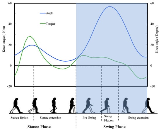
Figure 1.
A complete gait cycle. The relationship of knee angle and torque.
The main purpose of the prosthetic knee is to restore the motor function of the amputated knee by mimicking the behavior of the biological knee. Figure 1 shows the knee angle and torque curve of a normal person during a gait cycle. In this figure, the stride cycle begins and ends when the heel strikes the ground. As shown in the figure, toe off the ground occurs approximately 62% of the stride period. The initial flexion and extension of the knee joint keeps the center of gravity of the body relatively vertical and horizontal. The net power during the swing phase is basically negative, but the positive power output of the prosthesis is needed during the stance extension phase of the natural gait. The positive power output occurs in about 14% to 30% of the gait cycle, whereas the active torque cannot be provided by mechanical passive or variable damping prosthetic knee.
The key design objectives of the semi-active prosthetic knee are as follows:
- (1)
- The structure should have the ability to simulate the biological knee motion.
- (2)
- The active torque and passive damping should be provided alternately.
- (3)
- The weight, size, and energy consumption should be reduced compared to powered prostheses.
2.2. Bio-Inspired Design of the Knee Joint
The biological structure of the human knee joint is shown in Figure 2a. It consists of medial and lateral femoral condyle, tibial plateau, patella, anteriorly crossed ACL ligament, and PCL ligament. The shape of the contact surface between the lower end of femur and the upper end of tibia is irregular, and there is rolling and sliding between the two surfaces during flexion and extension. The trajectory of the curvature center of the horizontal rotation axis of the knee (Instantaneous Centre of Rotation (ICR)) is a J-shaped curve. The rotation center of single axial prosthetic knees cannot simulate the motion of the natural knee. In normal walking, the feet and the ground need a certain gap to avoid collision. To maintain this distance, many patients have to tilt their body during the swing phase, allowing the prosthesis to draw an arc on the horizontal plane. There is a tendency for prostheses to be shorter than healthy human legs when assembled with transfemoral amputees, and these methods not only affect the symmetry of the human gait but also have a significant impact on the stability of the human body. To solve this problem, the prosthetic knee joint designed in this paper adopts a four-bar mechanism. Due to the change of the ICR of the four-bar mechanism, the effective leg length of the prosthetic limb is shortened when the knee joint is bent, as shown in Figure 2b. Thus, amputees with intelligent bionic legs improve stability when walking on uneven surfaces, ramps, or stairs. The instantaneous center trajectory of the knee joint was the optimization objective; the multiaxis knee joint structure was optimized by using the multivariable optimization design method. The structural characteristics of the multiaxis knee joint, the swing angle range of the knee, and the requirements of the flexibility in the swing period were considered. The J-curve motion, which was the same with biological knee, was realized by the four-bar mechanism.
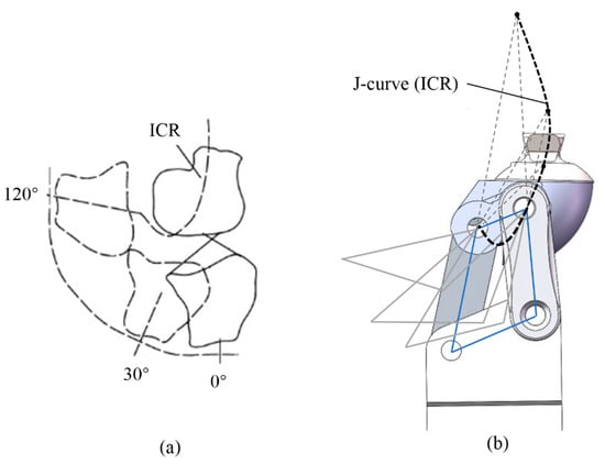
Figure 2.
Bio-inspired design of the knee joint. (a) The biological structure of the human knee; (b) Four-bar mechanism.
2.3. Design of the Semi-Active Prosthetic Knee
The active and passive structures of the prosthetic knee are shown in Figure 3. The thigh connector is connected to thigh socket in the upper side. The lower side is connected with the four-bar linkage. The upper piston rod is connected with the four-bar linkage by a drive link. For the variable damping control, the provided hydraulic system (Figure 3b) had one fan rotation valve, namely designed throttle valve, to generate joint resistance for the flexion and the extension movement. The position of the fan valve plate was controlled by the motor 1. The flow resistance could be continuously adjusted from low to high values by the rotation of the fan valve plate. When the piston rod moved down during knee flexion, the oil flowed through the throttle valve and one-way valve 1a in the flexion channel. The oil could not flow through the extension channel due to the unidirectional cutoff characteristic of the one-way valve 1b. The knee flexion damping could be regulated by the position change of the fan valve plate. The steel spring was stretched during knee flexion by the displacement of the upper piston. For the knee extension, the piston rod moved up and the oil flowed through the throttle valve and one-way valve 1b in the extension channel. The oil could not flow through the flexion channel due to the unidirectional cutoff characteristic of the one-way valve 1a. The knee extension damping was also adjusted by the position change of the fan valve plate. The energy stored by stretch of steel spring was released. This could provide assistance for knee extension. For the powered mode, the throttle valve is completely open. This means the passive hydraulic damping is free. The lower piston rod is driven by the ball screw. The vertical displacement of the ball screw is controlled by the synchronous belt connected to the motor 2. When the lower piston moved up, the upper piston was pushed up and the active knee torque was provided by the four-bar linkage. A hole exists on the lower piston rod to ensure that the oil flow is not affected by the up and down motion of the lower piston rod. The detailed structure of the hydraulic system and the prototype are shown in Figure 4.
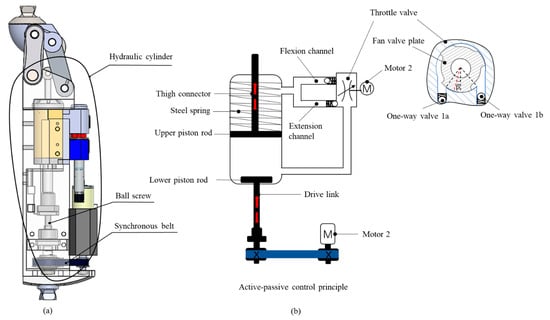
Figure 3.
The active and passive structures of the prosthetic knee. (a) The 3D model of the prosthetic knee; (b) The active and passive working principle.
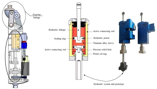
Figure 4.
The detailed structure of the semi-active system and the prototype.
The work scheme of the semi-active prosthetic knee is shown in Figure 5. At the beginning of stance in the human gait, the heel touches the ground. The calf quadriceps need to concentric contraction to increase the center of gravity and prevent the lateral foot in the swing phase from touching the ground. The knee joint provides positive work. We connect the motor 2 with the synchronous belt to output the active torque and transfer it to the ball screw. The transmitted torque of the ball screw is controlled by adjusting the speed of the motor 2. Therefore, the torque needed by the human body to do positive work is outputted by the motor 2. When the knee joint enters the swing flexion phase, the side leg touches the ground and the hip joint begins to flex. At this time, the hydraulic damping cylinder works. The pressure between the upper and lower oil chambers of the hydraulic cylinder is changed by the position change of the fan valve plate. The real-time damping torque was provided by this operation. During the swing extension phase, the extension damping torque was provided to slow the foot movement to the initial velocity of contact with the ground. Due to the fact that the prototype is currently in the processing state, the sensor system is not completely determined. In terms of control, the design mentioned in this paper will mainly use angle sensor, IMU, and force sensor to identify the gait cycle and control the position of the rotating valve. The sensor system can consider our previous work [].
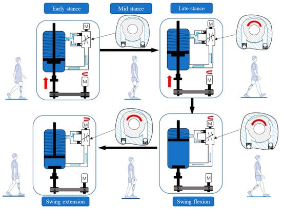
Figure 5.
The work scheme of the semi-active prosthetic knee.
2.4. Mathematical Model of the Hydraulic Damping and Active Torque
The damping of the hydraulic system of the prosthetic knee is composed of spring damping and hydraulic fluid damping. The adjustment of the hydraulic damping is the core of the control of the prosthetic knee. In order to obtain the ideal hydraulic damping force, it is necessary to establish the calculation model of the hydraulic damping system to determine the relationship between the output damping force and the flow area of the throttle valve. In the case that the structure of the hydraulic damping cylinder and the nature of the hydraulic fluid are certain, the output damping force is related to the velocity of the upper piston in the cylinder and the flow area of the throttle valve []. When the prosthetic knee joint rotates, the hydraulic damping cylinder produces the real-time changed damping force. The prosthetic knee provides appropriate hydraulic damping force for the knee flexion and extension in the different gait phases of the transfemoral amputee.
The actual knee joint damping torque generated by the hydraulic damper is M
K is the elastic coefficient of the extensor spring, ∆x is the compression of the spring, L is the length of the real-time moment arm, ∆P is the pressure difference between upper and lower chamber, and the effective acting area of the piston is A.
The force transmission of the prosthetic knee is shown in Figure 6.
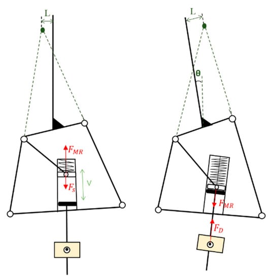
Figure 6.
The force transmission of the prosthetic knee.
The hydraulic damping force can be calculated as
The velocity of the damper piston is V, the effective flow area of the hydraulic oil flow through the valve is , the flow coefficient is , and the hydraulic oil density is ρ, then
and
When the active torque is provided by the prosthetic knee joint, the throttle valve of the hydraulic cylinder is in a fully open state. According to the torque change curve of the human knee joint, it can be seen from Figure 1 that the torque change is nonlinear. Thus, the torque provided by the motor to the ball screw should be accelerated in variable motion.
When the ball screw mechanism accelerates, the axial load of the ball screw mechanism in the operation process comes from the movement resistance or external axial force of the guide surface of the inverted rod mechanism (such as linear guide rail and linear bearing). Axial load of ball screw can be calculated as
where is the external axial force acting on the nut (e.g., cutting force, etc.). When the system is only used for the reciprocating movement of the workpiece, there is no external axial force acting on the workpiece. is the mass of the load slider (including the workpiece). is the motion resistance of linear guide pair without load. is the friction coefficient of linear guide pair.
The driving torque required by a motor in constant speed motion is
where, is the lead of the lead screw. is the transmission efficiency of the ball screw pair, and is the deceleration ratio of the motor to the screw.
The torque required to accelerate the motion
The formula for calculating the torque provided by the ball screw and the motor speed n is:
where is motor power; is the transmission efficiency of synchronous belt
In the active stage, the damping cylinder cannot provide the active torque. In order to better adapt to the movement of human body, the adjusting valve of the hydraulic cylinder is fully open in the stage when the active torque is needed. The movement of the piston is driven by the lower piston connected by the ball screw to provide the active torque of the upper piston to the knee joint, and the moment is
In the passive stage, the lower piston is separated from the upper piston, and the valve opening of the hydraulic cylinder is adjusted according to the damping torque provided. The hydraulic cylinder only acts as a damping cylinder to provide passive damping torque for the knee joint, and the moment is
2.5. Simulation Process
The ADAMS software was used to conduct the simulation. The parameters and values of the hydraulic cylinder are shown in Figure 7 and Table 1. To obtain the torque provided by the prosthetic knee, the piston velocity V and arm L in a gait cycle should be calculated by simulation firstly. The angular velocity curve of the knee joint in the normal gait [] was transformed into spline curve to add driving force to the prosthetic knee for motion simulation. The velocity curve of the upper piston in the prosthetic knee joint, V (mm/s), and the real-time moment arm L (mm) of the prosthetic knee joint were obtained, as shown in Figure 8. The piston rod speed was smooth and the length change of the knee moment arm was in the range. The torque simulation process in the ADAMS and human body parameters setting are shown in Figure 9 and Table 2.
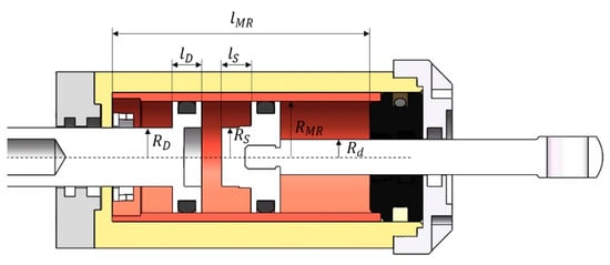
Figure 7.
The parameters of the hydraulic cylinder.

Table 1.
The values of the parameters in simulation.
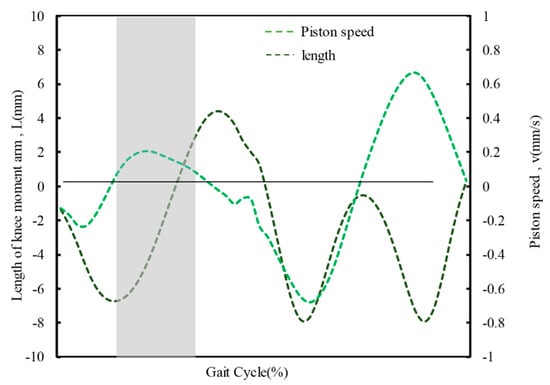
Figure 8.
The velocity of the upper piston and the real-time moment arm of the prosthetic knee.
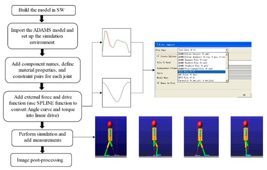
Figure 9.
The torque simulation process in the ADAMS.

Table 2.
Human body parameters setting in ADAMS.
2.6. Performance Evaluation Parameters
Normal gait is a cyclic and symmetric process depending on the continuous and complex transfer of energy among the body segments []. Symmetry appears to be a relevant aspect for differentiating a normal and pathologic gait; lower limb amputees experience pathological gaits which are often asymmetric and less stable than non-amputees. The gait symmetry compares the kinematics and kinetics of the intact side and prosthetic side. It is a key index of the performance of the prosthetic knee []. The gait symmetry quantification used three indices introduced by Karaharju-Huisman et al. [].
- (1)
- Symmetry Index (SI)
- (2)
- Ratio I
- (3)
- Ratio II
3. Results
3.1. Symmetry of Knee Torque
Combined with MATLAB software solution and the mathematical model, the torque provided by the prosthetic knee was calculated (Figure 10). The active torque and passive torque could be provided alternately. The active phase is about from 15% to 30% and the other is passive phase. The work mode was similar to the normal knee joint. The symmetry indices data calculated of the knee torque are shown in Table 3. The number values of SI were smaller than 10% in the whole gait. The knee torque symmetry of swing phase was higher than the stance phase. The dominance was prosthetic knee in stance phase while it was the intact knee in swing phase. It means the active torque and hydraulic damping can simulate the active-passive working principle of the biological knee.
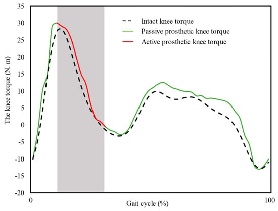
Figure 10.
The prosthetic knee torque and intact knee torque.

Table 3.
The knee torque symmetry.
3.2. Symmetry of Knee Angle
The knee angle was also obtained by simulation. The knee angle acquirement scheme is shown in Figure 11. The equivalent model was established in Adams (MSC software). The normalized hip angle (θ) and the prosthetic knee torque obtained by simulation were set as the driving source in the Adams simulation environment. The active torque and passive torque provide corresponding drivers for simulation model in the active and passive stages in the gait cycle, respectively.
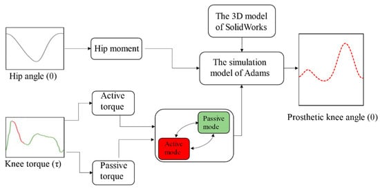
Figure 11.
The knee angle acquirement scheme.
Figure 12 shows the normalized angle and the prosthetic knee angle during a gait cycle. The angle change trend of the prosthetic knee is basically consistent with the normal knee in the hybrid drive mode. The symmetry indices data calculated were shown in Table 4. The SI value is 34.7% in stance phase and 11.5% in swing phase. The angle in swing phase is closer to the intact knee. The prosthetic knee angle is smaller than the intact knee in stance phase. This means the angle range of stance extension is smaller than that of the prosthetic knee.
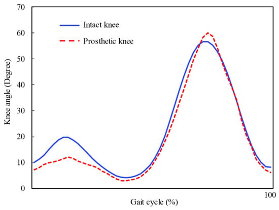
Figure 12.
The intact knee angle and the prosthetic knee angle.

Table 4.
The knee angle symmetry.
4. Discussion
This work presented a novel semi-active prosthetic knee with ball-screw driven by the motor and variable hydraulic damping cylinder. The model established can be applied to simulation for the performance estimation of the prosthetic knee. The torque and angle symmetry were realized of the proposed prosthetic knee in simulation. The semi-active mode is biological of intact knee and beneficial for energy saving.
The pneumatic IP just adjusted damping in swing phase [], while both the stance and swing phases were controlled by the motor and variable hydraulic damping cylinder alternately for the proposed semi-active knee. Compared with the structures of the typical hydraulic damping prosthetic knees Genium and C-leg [], the proposed semi-active knee can provide active torque, which is important for the stair ascent and slope up. The active knee-ankle prosthesis proposed in [,,,] are too heavy for clinical use. The energy consumption of purely active prosthetic knees [,,,] is also higher than the proposed semi-active prosthetic knee in this work. Although the prosthetic knees in [,,] were semi-active by hydraulic system, the hydraulic pumps were still too heavy. The work [] presented a semi-active knee with a magnetorheological damper and a motor. The active torque was provided by the motor coaxial to the knee joint, while the ICR motion was simulated by four-bar mechanism in this work.
Although the semi-active prosthetic knee is novel, a number of limitations of this work exist. The work was conducted in simulation. The physical prototype is currently in the processing state. The physical experiment data has not been tested yet. The human test will be done in the following work. The evaluation parameter was not enough. We will test the speed adaption ability of the semi-active prosthetic knee.
5. Conclusions
In this work, a prosthetic knee for transfemoral amputees that can be operated in semi-active and variable damping modes was proposed. The instantaneous center motion of the human knee joint is reproduced by the four-bar structure design. The active torque and the variable damping can be adjusted by the semi-active prosthetic knee. The control of swing flexion and extension is realized by the variable hydraulic damping cylinder. The stance extension torque is provided by the ball-screw driven by the motor. By the hybrid drive mode, the knee joint can better simulate the torque changes of the knee joint and improve gait symmetry. It has good potential to improve the life quality of the transfemoral amputee.
Author Contributions
Conceptualization, Z.Z. and X.W.; methodology and software, Z.Z.; formal analysis and investigation, W.C.; writing—original draft preparation, Z.Z.; writing—review and editing, W.C. and H.Y.; writing—revision and response, Q.M. and C.C.; supervision, H.Y.; funding acquisition, H.Y. and W.C. All authors have read and agreed to the published version of the manuscript.
Funding
This research was funded by the National Natural Science Foundation of China, grant number 62073224, 62003327, the National Key R&D Program of China, grant number 2018YFB1307303, Guangdong Basic and Applied Basic Research Foundation, grant number 2021A1515011699, 2019A1515110576.
Institutional Review Board Statement
Not applicable.
Informed Consent Statement
Not applicable.
Data Availability Statement
The readers can obtain the data from authors.
Acknowledgments
We are supported by the Shenzhen Institute of Artificial Intelligence and Robotics for Society.
Conflicts of Interest
The authors declare no conflict of interest.
References
- Bekrater-Bodmann, R. Factors Associated With Prosthesis Embodiment and Its Importance for Prosthetic Satisfaction in Lower Limb Amputees. Front. Neurorobot. 2021, 14, 604376. [Google Scholar] [CrossRef]
- Cao, W.J.; Yu, H.L.; Zhao, W.L.; Li, J.; Wei, X.D. Target of physiological gait: Realization of speed adaptive control for a prosthetic knee during swing flexion. Technol. Health Care 2018, 26, 133–144. [Google Scholar] [CrossRef] [PubMed]
- Chaparro-Rico, B.D.M.; Cafolla, D. Test-retest, inter-rater and intra-rater reliability for spatiotemporal gait parameters using SANE (an eaSy gAit aNalysis systEm) as measuring instrument. Appl. Sci. 2020, 10, 5781. [Google Scholar] [CrossRef]
- Chaparro-Rico, B.D.M.; Cafolla, D.; Castillo-Castaneda, E.; Ceccarelli, M. Design of arm exercises for rehabilitation assistance. J. Eng. Res. Kuwait 2020, 8, 203–218. [Google Scholar] [CrossRef]
- Hutabarat, Y.; Ekkachai, K.; Hayashibe, M.; Kongprawechnon, W. Reinforcement Q-Learning Control with Reward Shaping Function for Swing Phase Control in a Semi-active Prosthetic Knee. Front. Neurorobot. 2020, 14, 565702. [Google Scholar] [CrossRef] [PubMed]
- Kaufman, K.R.; Frittoli, S.; Frigo, C.A. Gait asymmetry of transfemoral amputees using mechanical and microprocessor-controlled prosthetic knees. Clin. Biomech. 2012, 27, 460–465. [Google Scholar] [CrossRef]
- Hafner, B.J.; Askew, R.L. Physical performance and self-report outcomes associated with use of passive, adaptive, and active prosthetic knees in persons with unilateral, transfemoral amputation: Randomized crossover trial. J. Rehabil. Res. Dev. 2015, 52, 677–699. [Google Scholar] [CrossRef]
- Chin, T.; Sawamura, S.; Shiba, R.; Oyabu, H.; Nagakura, Y.; Takase, I.; Machida, K.; Nakagawa, A. Effect of an intelligent prosthesis (IP) on the walking ability of young transfemoral amputees—Comparison of IP users with able-bodied people. Am. J. Phys. Med. Rehabil. 2003, 82, 447–451. [Google Scholar] [CrossRef]
- Lura, D.J.; Wernke, M.M.; Carey, S.L.; Kahle, J.T.; Miro, R.M.; Highsmith, M.J. Differences in knee flexion between the Genium and C-Leg microprocessor knees while walking on level ground and ramps. Clin. Biomech. 2015, 30, 175–181. [Google Scholar] [CrossRef]
- Bellmann, M.; Kohler, T.M.; Schmalz, T. Comparative biomechanical evaluation of two technologically different microprocessor-controlled prosthetic knee joints in safety-relevant daily-life situations. Biomed. Eng. Biomed. Tech. 2019, 64, 407–420. [Google Scholar] [CrossRef]
- Clarke, L.; Dillon, M.P.; Shiell, A. A systematic review of health economic evaluations in orthotics and prosthetics: Part 1-prosthetics. Prosthet. Orthot. Int. 2020, 45, 62–75. [Google Scholar] [CrossRef] [PubMed]
- Lawson, B.E.; Mitchell, J.E.; Truex, D.; Shultz, A.; Ledoux, E.; Goldfarb, M. A robotic leg prosthesis: Design, control, and implementation. IEEE Robot. Autom. Mag. 2014, 21, 70–81. [Google Scholar] [CrossRef]
- Khademi, G.; Simon, D. Toward Minimal-Sensing Locomotion Mode Recognition for a Powered Knee-Ankle Prosthesis. IEEE Trans. Biomed. Eng. 2021, 68, 967–979. [Google Scholar] [CrossRef] [PubMed]
- Elery, T.; Rezazadeh, S.; Nesler, C.; Gregg, R.D. Design and Validation of a Powered Knee-Ankle Prosthesis With High-Torque, Low-Impedance Actuators. IEEE Trans. Robot. 2020, 36, 1649–1668. [Google Scholar] [CrossRef] [PubMed]
- Mendez, J.; Hood, S.; Gunnel, A.; Lenzi, T. Powered knee and ankle prosthesis with indirect volitional swing control enables level-ground walking and crossing over obstacles. Sci. Robot. 2020, 5, eaba6635. [Google Scholar] [CrossRef] [PubMed]
- Stolyarov, R.; Carney, M.; Herr, H. Accurate Heuristic Terrain Prediction in Powered Lower-Limb Prostheses Using Onboard Sensors. IEEE Trans. Biomed. Eng. 2021, 68, 384–392. [Google Scholar] [CrossRef] [PubMed]
- Lansade, C.; Chiesa, G.; Paysant, J.; Vicaut, E.; Cristina, M.C.; Menager, D. Impact of C-LEG on mobility, satisfaction and quality of life in a multicenter cohort of femoral amputees. Ann. Phys. Rehabil. Med. 2021, 64, 101386. [Google Scholar] [CrossRef]
- Thiele, J.; Schollig, C.; Bellmann, M.; Kraft, M. Designs and performance of three new microprocessor-controlled knee joints. Biomed. Eng. Biomed. Tech. 2019, 64, 119–126. [Google Scholar] [CrossRef] [PubMed]
- Elery, T.; Rezazadeh, S.; Reznick, E.; Gray, L.; Gregg, R.D. Effects of a Powered Knee-Ankle Prosthesis on Amputee Hip Compensations: A Case Series. IEEE Trans. Neural Syst. Rehabil. Eng. 2020, 28, 2944–2954. [Google Scholar] [CrossRef]
- Lambrecht, B.G.A.; Kazerooni, H. Design of a Semi-Active Knee Prosthesis. In Proceedings of the IEEE International Conference on Robotics and Automation (ICRA), Kobe, Japan, 12–17 May 2009; pp. 4097–4103. [Google Scholar] [CrossRef]
- Pillai, M.V.; Kazerooni, H.; Hurwich, A. Design of a Semi-Active Knee-Ankle Prosthesis. In Proceedings of the IEEE International Conference on Robotics and Automation (ICRA), Shanghai, China, 9–13 May 2011; pp. 5293–5300. [Google Scholar] [CrossRef]
- Awad, M.; Dehghani, A.; Moser, D.; Zahedi, S. Dynamic Coupling Characteristics of a Semi-Active Knee Prosthesis. In Proceedings of the Conference on Climbing and Walking Robots (CLAWAR), Sydney, Australia, 14–17 July 2013; pp. 43–50. [Google Scholar]
- Park, J.; Yoon, G.H.; Kang, J.W.; Choi, S.B. Design and control of a prosthetic leg for above-knee amputees operated in semi-active and active modes. Smart Mater. Struct. 2016, 25, 085009. [Google Scholar] [CrossRef]
- Cao, W.; Yu, H.; Chen, W.; Meng, Q.; Chen, C. Design and evaluation of a novel microprocessor-controlled prosthetic knee. IEEE Access 2019, 7, 178553–178562. [Google Scholar] [CrossRef]
- Cao, W.; Yu, H.; Meng, Q.; Li, S. Plantar pressure analysis of Above-knee Amputee with a Developed Microprocessor-controlled Prosthetic Knee. Acta Bioeng. Biomech. 2018, 20, 33–40. [Google Scholar] [CrossRef] [PubMed]
- Cao, W.; Zhao, W.; Yu, H.; Chen, W.; Meng, Q. Maximum swing flexion or gait symmetry: A comparative evaluation of control targets on metabolic energy expenditure of amputee using intelligent prosthetic knee. BioMed Res. Int. 2018, 2018, 2898546. [Google Scholar] [CrossRef] [PubMed]
- Jason HMKahle, J.T.; Wernke, M.M.; Carey, S.L.; Miro, R.M.; Lura, D.J.; Sutton, B.S. Effects of The Genium Knee System on Functional Level, Stair Ambulation, Perceptive and Economic Outcomes in Transfemoral Amputees. Technol. Innov. 2016, 18, 139–150. [Google Scholar] [CrossRef]
- Sutherland, D.H. The evolution of clinical gait analysis: Part II Kinematics. Gait Posture 2002, 16, 159–179. [Google Scholar] [CrossRef]
- Aslani, N.; Noroozi, S.; Yee, K.S.; Chao, A.O.Z.; Maggs, C. Simulation of gait asymmetry and energy transfer efficiency between unilateral and bilateral amputees. Sports Eng. 2016, 19, 163–170. [Google Scholar] [CrossRef][Green Version]
- Pagel, A.; Arieta, A.H.; Riener, R.; Vallery, H. Effects of sensory augmentation on postural control and gait symmetry of transfemoral amputees: A case description. Med. Biol. Eng. Comput. 2015, 54, 1579–1589. [Google Scholar] [CrossRef] [PubMed]
- Karaharju-Huisnan, T.; Taylor, S.; Begg, R.; Cai, J.; Best, R. Gait symmetry quantification during treadmill walking. In Proceedings of the Seventh Australian and New Zealand Intelligent Information Systems Conference, Perth, Australia, 18–21 November 2001; pp. 203–206. [Google Scholar]
Publisher’s Note: MDPI stays neutral with regard to jurisdictional claims in published maps and institutional affiliations. |
© 2021 by the authors. Licensee MDPI, Basel, Switzerland. This article is an open access article distributed under the terms and conditions of the Creative Commons Attribution (CC BY) license (https://creativecommons.org/licenses/by/4.0/).