Article

HP-SFC: Hybrid Protection Mechanism Using Source Routing for Service Function Chaining

1
Department of Electrical and Computer Engineering, Sungkyunkwan University, Suwon 16419, Korea
2
Defense Security Institute, Korea Ministry of National Defense, Seoul 04383, Korea
3
Department of IT Convergence Software, Seoul Theological University, Bucheon 14754, Korea
4
Department of Computer Science and Engineering, Sungkyunkwan University, Suwon 16419, Korea
*
Authors to whom correspondence should be addressed.
Appl. Sci. 2021, 11(11), 5245; https://doi.org/10.3390/app11115245
Submission received: 3 May 2021 / Revised: 26 May 2021 / Accepted: 1 June 2021 / Published: 4 June 2021
(This article belongs to the Special Issue Cloud Computing Beyond)

Abstract

:
Service Function Chaining (SFC) is an emerging paradigm aiming to provide flexible service deployment, lifecycle management, and scaling in a micro-service architecture. SFC is defined as a logically connected list of ordered Service Functions (SFs) that require high availability to maintain user experience. The SFC protection mechanism is one way to ensure high availability, and it is achieved by proactively deploying backup SFs and installing backup paths in the network. Recent studies focused on ensuring the availability of backup SFs, but overlooked SFC unavailability due to network failures. This paper extends our previous work to propose a Hybrid Protection mechanism for SFC (HP-SFC) that divides SFC into segments and combines the merits of local and global failure recovery approaches to define an installation policy for backup paths. A novel labeling technique labels SFs instead of SFC, and they are stacked as per the order of SFs in a particular SFC before being inserted into a packet header for traffic steering through segment routing. The emulation results showed that HP-SFC recovered SFC from failure within 20–25 ms depending on the topology and reduced backup paths’ flow entries by at least 8.9% and 64.5% at most. Moreover, the results confirmed that the segmentation approach made HP-SFC less susceptible to changes in network topology than other protection schemes.

1. Introduction

Network softwarization technologies such as Network Function Virtualization (NFV) and Software-Defined Networking (SDN) have enabled the provisioning of dynamic end-to-end services in 5G, Internet of Things, Industry 4.0, and other emerging trends. Traditionally, a service used to be a combination of various functions, statically deployed at a single or multiple locations. With NFV, functions in a service are separated and virtualized through Virtual Machines (VMs) or containers and are termed Virtual Network Functions (VNFs) or Service Functions (SFs). An orderly connected list of SFs, known as Service Function Chaining (SFC), delivers a specific service [1]. This not only enables operators to dynamically scale services, but also quickly provision new services by changing the order of SFs in SFC [2]. To satisfy the demand for uninterrupted high-quality services, in particular after the COVID-19 pandemic, the high availability of SFC is of paramount importance for operators under ever-increasing traffic load [3].
High availability for SFC requires an instant protection mechanism from the failure of network infrastructure (i.e., links, switches, servers) or software (i.e., VMs, containers). The protection mechanism for SFC stipulates that backup paths and SFs are installed at the initiation time of SFC. In the case of any failure event, the traffic is rerouted to the pre-installed backup path towards pre-deployed backup SFs. The protection mechanisms in conventional SDNs [4,5] are not applicable to SFC, because the traffic in SFC needs to be routed through multiple intermediate destinations (i.e., SFs) in a given order before reaching the final destination. Additionally, the locations of backup SFs are not fixed as they are dynamically deployed after SFC creation depending on available resources and the proximity to the primary SFs. These SFC characteristics make the protection mechanism more complex than in conventional SDN.
The protection of SFC consists of three sub-tasks: placement of backup SFs, decision regarding individual or shared backup SFs and their selection criteria, and proactive installation of backup paths and a traffic rerouting mechanism. Intuitively, the cost of backup path installation and end-to-end transmission delay become significant if the backup SFs are deployed at distant servers. On the contrary, the probability of the backup SFs’ inaccessibility increases if they are placed in close proximity to their respective primary SFs. Most of the SFC recovery-related studies focused on this and increased SFC survivability by optimizing different parameters related to the placement of backup SFs [6,7,8]. Another concern related to the backup SFs’ placement is the additional resource footprint, which is maximum in the case of a 1:1 mapping between primary and backup SFs. Sharing of backup SFs through M:N mapping between primary and backup SFs reduces the additional resource footprint, where M > N [9,10]. These studies increased the network utilization and reduced end-to-end delay, but lacked a strategy for backup path setup with minimal installation cost and rerouting delay.
Proactive installation of backup paths and a traffic rerouting mechanism for SFC protection seems trivial, but can result in high recovery delay and an increased number of control messages and flow entries, if not designed diligently. Approaches such as global and local protection from conventional networks either cause significant resource under-utilization or a critical increase in end-to-end transmission delays. This entails a backup path installation and traffic rerouting mechanisms (here onwards, the backup path installation and traffic rerouting mechanism are termed SFC protection for brevity),which benefit from the minimum end-to-end transmission delay and rapid recovery characteristics of global and local protection approaches, respectively, while avoiding their drawbacks. Moreover, the use of many flow entries by the SFC protection mechanism results in increased control messages between the SDN controller and switches and flow table overflows in software-defined switches. Hence, it must use the minimum number of flow entries for rerouting the traffic to and from the backup SF to reduce the flow table occupancy problem. Our previous study used source routing to route traffic through SFC and presented failure recovery as a use-case to show its effectiveness, but it exhibited some limitations in terms of flow table design [11]. To address the aforementioned SFC protection requirements and limitations of [11], this paper extends our previous work to a hybrid SFC protection mechanism that provides more robust traffic steering through a refined flow entry update mechanism.
The proposed hybrid SFC protection mechanism (HP-SFC) segregates SFC into segments, where a segment is defined as a path from one primary SF to the next ( S F i , S F ( i + 1 ) ] . Each segment is covered by a single backup SF, and the failure of the primary SF or any network element in the path to it is taken as the failure of the whole segment. HP-SFC reroutes the traffic from the starting point of the failed segment to the backup SF, and from there, it uses the new segment to route traffic to the next primary SF in SFC. The proposed approach resembles global protection from the segment perspective, and from the SFC point of view, it is similar to local protection; hence, it is termed the hybrid protection mechanism. Moreover, flow entry updates required by HP-SFC to reroute the traffic from failed SF to backup SF are reduced through a novel per-SF labeling technique. The contributions of this paper can be summarized as follows:
  • A novel SF labeling technique for traffic steering and rerouting in SFC that reduces the flow table occupancy in the software switches and Service Function Forwarders (SFFs) and improves network capacity;
  • A new and simplified flow entries’ update process for traffic re-routing, which parallelizes the sending of update messages and requires fewer flow entry updates, consequently reducing the recovery delay and control overhead;
  • A hybrid protection approach that combines the merits of local and global protection to balance the tradeoff between end-to-end transmission delay and the cost of a protection mechanism in terms of additional resources in network entities;
  • A comprehensive evaluation and analysis of HP-SFC in Mininet with two distinct topologies representing a data center and enterprise networks.
The remainder of paper is as follows. Section 2 defines SFC creation, operation, and routing techniques and discusses current protraction approaches in the literature for SDNs and SFC. Section 3 presents the HP-SFC architecture and describes the hybrid protection mechanism through the proposed per-SF labeling technique. A proof-of-concept emulation environment is discussed in Section 4 along with the detailed evaluation results based on different topologies. The concluding discussion on the merits and limitations of HP-SFC is presented in Section 5 along with future directions for improvement.

2. Failure Recovery in SFC and Challenges

This section is structured into three parts to define the scope of this study, discuss background technologies, and present a review of recent studies. SFC failure recovery consists of multiple sub-tasks such as the placement of backup SFs, deployment, and path setup, which are incorporated into different phases of the SFC creation process. The first part of this section describes the creation and management of SFC to define the scope of the proposed protection mechanism. The latter part of the section explains segment routing and convention failure recovery approaches that play a fundamental role in the proposed HP-SFC. The last part presents recent studies related to different aspects of failure recovery in SFC in the context of the proposed protection mechanism.

2.1. SFC Creation and Operation

A new service request triggers the creation of SFC at the service overlay layer, which is later embedded into the underlay network layer through an embedding function. The overlay layer creates a directed graph of logical connections among SFs in a specific order to logically represent SFC for the requested service. This graph representation of SFC is called the Virtual Network Function Forwarding Graph (VNF-FG), and we take each hop in the VNF-FG, from one SF to the next, as a segment in the overlay layer. The underlay network is defined as the topology of physical links connecting different network elements. The embedding function maps each segment in the VNF-FG to one or more hops in the underlay network. Hence, SFC is a logical VNF-FG in the overlay layer that is then embedded into the physically interconnected underlay network [12].
The SFC creation process is defined in the NFV management and orchestration (MANO) reference architecture by ETSI [12]. It consists of the NFV Orchestrator (NFVO), VNF Manager (VNFM), and Virtualized Infrastructure Manager (VIM). Service requests are received by the NFVO, and it creates a representative SFC model for the service to define the VNF-FG. Based on the available capacity of the physical servers and current usage of the network resources, the NFVO determines the optimal sites in physical servers for SFs’ deployment using VMs/containers [13] or selects the best-suited SF from already deployed instances [14]. SFs’ deployment and traffic routing information is then passed onto the VNFM and VIM for resource allocation, placement, and path selection in the physical infrastructure and underlay network. After deployment completion, the SDN controller installs the entries for traffic routing through SFC based on the received paths and policies.
The protection of SFC from failure requires the NFVO to create a backup VNF-FG with backup SFs. The VNFM and VIM take care of the placement and deployment of the backup SFs in the physical servers, and the SDN controller handles the setup of backup paths and traffic re-routing in the case of failure. The focus of this paper was to reduce the resource footprint of backup paths and expedite the traffic re-routing functionalities of the SDN controller while taking the locations of backup SFs as the input.

2.2. Segment Routing

Network traffic flows must traverse ordered segments in SFC, where a segment is a route from one SF to the next. Conventional routing approaches create a path between a single source and destination; on the contrary, SFC has multiple sources and destinations as the starting and ending SFs of each segment are treated as the source and destination. The Network Service Header (NSH) protocol is designed to route traffic flows through SFC [15], where packets are encapsulated by outer transport encapsulation. The Service Path Header (SPH) is the main part of the NSH, and it stores the SFC path. The SPH consists of a 24-bit Service Path Identifier (SPI) indicating which path in SFC is to be used and an eight-bit Service Index (SI) that defines the number of SFs traversed in the SPI. Together, the SPI and SI values define the current path and the SF the packet is traversing. A major drawback of the NSH is that the SPI is per path and not per SFC; this means that a new SPI must be created when part of the SFC path is changed. This increases the flow entries to distinguish new SPI and SI combinations and requires the update of both the SPI and SI for re-routing due to failure.
Segment Routing (SR) resembles source routing where a complete path is added in the packet through an additional header at the ingress node. The path in the additional header is defined by an ordered list of labels representing network elements (i.e., SFs) to be traversed. Multi-Protocol Label Switching (MPLS) [16] is one of the protocols that can be used to implement SR. The MPLS header with the ordered labels is added to the packet by the ingress router of the network, and each label represents one segment in SFC. The core routers in the network use these labels to route the packets to appropriate destinations, and the label of a segment is popped out once it is traversed. Due to the limitations of the NSH, this paper defined SFC traffic routing and failure recovery mechanism through SR and implemented them in underlay network by using stacked labels in the MPLS header.

2.3. Limitations of Conventional Failure Recovery Mechanisms in SFC

Three kind of failures can occur in SFC: (1) the failure of a link or a network entity in a path from one SFF to the next SFF; (2) the failure of the SFF; and (3) the failure of the SF [15]. We can replace the case of SF failure with the link to the SF failure, because a fully functional SF is useless if it is not accessible. SFF failure is more serious, as it can disrupt many of the SFC due to the relatively high number of links connected to it. However, network link failures are 155% more likely to happen than network node failures, as per [17]. Therefore, this study focused on protection from the failure of the link between two SFFs (Type 1) and the link between the SFF and SF (Type 3).
Traditional local and global failure recovery methods can be applied to failure cases in SFC. The local detouring techniques set a backup path for each individual link in the network. In the underlay network, the connection between two consecutive SFFs may consist of a single hop or multiple hops. It is sufficient to provide a local detouring path in the case of a single hop; however, in the case of multiple hops, the cost of setting up individual local detouring paths for the link in each hop is very high in terms of initial setup and idle resource occupancy. Switches at the either end of the link store a separate backup path for every link to which it connects. Moreover, local failure recovery techniques cannot recover the failure of the SFF to SF link, as a single link connects the SFF to SF and has to detour traffic to backup the SF. In summary, local failure recovery techniques cannot cover all types of failures in SFC and cause resource under-utilization with a high initial setup cost.
Global failure recovery is simpler than local failure recovery, as a shortest disjoint backup path is installed at the time of the initial path setup. This causes computational overhead at the controller at the time of initialization along with high idle resource occupancy, but shows better performance in terms of end-to-end transmission delay. In SFC, global recovery can be applied in multiple ways. Either a global backup SFC can be deployed with all backup SFs or a backup path for each segment can be installed. However, none of these approaches are efficient at recovering from all types of failures in SFC. The limitations of local and global failure recovery mechanisms for Type 1 and Type 3 failures in SFC are further explained through Figure 1a,b, respectively. SFC in Figure 1 is given as { S F 1 , S F 2 } with backups { S F 1 , S F 2 }, respectively. The proposed HP-SFC utilizes the strengths of local and global recovery mechanisms in a hybrid approach and reduces their weaknesses.

2.4. Software-Defined Failure Recovery Studies’ Review

Studies related to SFC protection can be divided into two categories. The first category consists of studies that focus on reducing the probability of failure by observing the state of network elements and virtualized resources during the placement and deployment phases of SFC creation. One such study calculated the probability of failure by modeling the deterioration of network nodes and links under specific conditions [6]. It proposed the R-SFC-MCTS algorithm, which constructs the SFC path by avoiding nodes or links with a high probability of failure through the decision tree. As a result, the probability of SFC failure is lowered, and in the case of failure, the decision tree must be reconstructed to select a new path. Another work focused on the placement of SFs based on the different characteristics of the network infrastructure [18]. The number of SFs and their placements were modeled using the availability of links and physical/virtual infrastructure through various algorithms. However, if the calculated availability of a network element satisfied the requirement set by the user, the backup path was not created to counter potential failure.
The second category consists of studies that focus on implementing an SFC failure recovery mechanism during the SFC path setup phase, and the proposed HP-SFC belongs to this category. Prompt and efficient SFC recovery requires a simplified traffic rerouting technique that is implemented through SR in the SFC environment by using protocols such as MPLS and IPv6 [19]. SR uses edge routers, directly connected to the hosts, to classify traffic and add the header with the ordered label stack. The order of labels represents the order of the SFs in SFC and the core router traffic using the label stack. SR-based traffic steering is extended for failure recovery in a multi-domain network environment [20], where each switch stores an alternative routing table for each segment. In the event of link failure, it changes the entire table to the alternate table to detour traffic to the backup path. However, the backup path does not make sure that all the segments in the original path are traversed, and this makes it inapplicable to SFC. Another study used SR and the labeling technique to propose a Segment-based SFC Protection (SSP) scheme that split SFC into different service segments [21]. It used input and output port numbers along with group tables to configure backup paths instead of labels, and that made it inflexible in software-defined network infrastructures, where the topology can be easily changed through the deployment of software switches. Moreover, due to the combined use of labels and port numbers for traffic forwarding, this results in additional flow entry installations in SSP.
Traffic detouring techniques for network protection are more thoroughly studied in SDNs, and parts of them can be transformed to become applicable to SFC protection. A local failure recovery scheme for both link and switches was implemented using the fast-failure group functionality of OpenFlow, which is the de facto protocol for communication between the SDN controller and softwarized switches [21]. At network initialization, the flow entries are proactively installed in the fast-failure group table of switches to establish backup paths based on the local recovery approach. In the case of failure, the status of the active port in the fast-failure group changes to down, and traffic is automatically forwarded to the failover port, representing the backup path. This approach was further extended for multi-link failures in a network with different levels of resiliencies [5]. These schemes cannot be directly applied to failure cases in SFC, because SFC consists of multiple intermediate destinations. Contrary to the proactive backup path setup, a hybrid method proactively calculates the backup paths, but installs them only when the failure occurs [22]. Although this saves flow table resources, it increases the recovery delay.

3. Hybrid Protection Mechanism for SFC

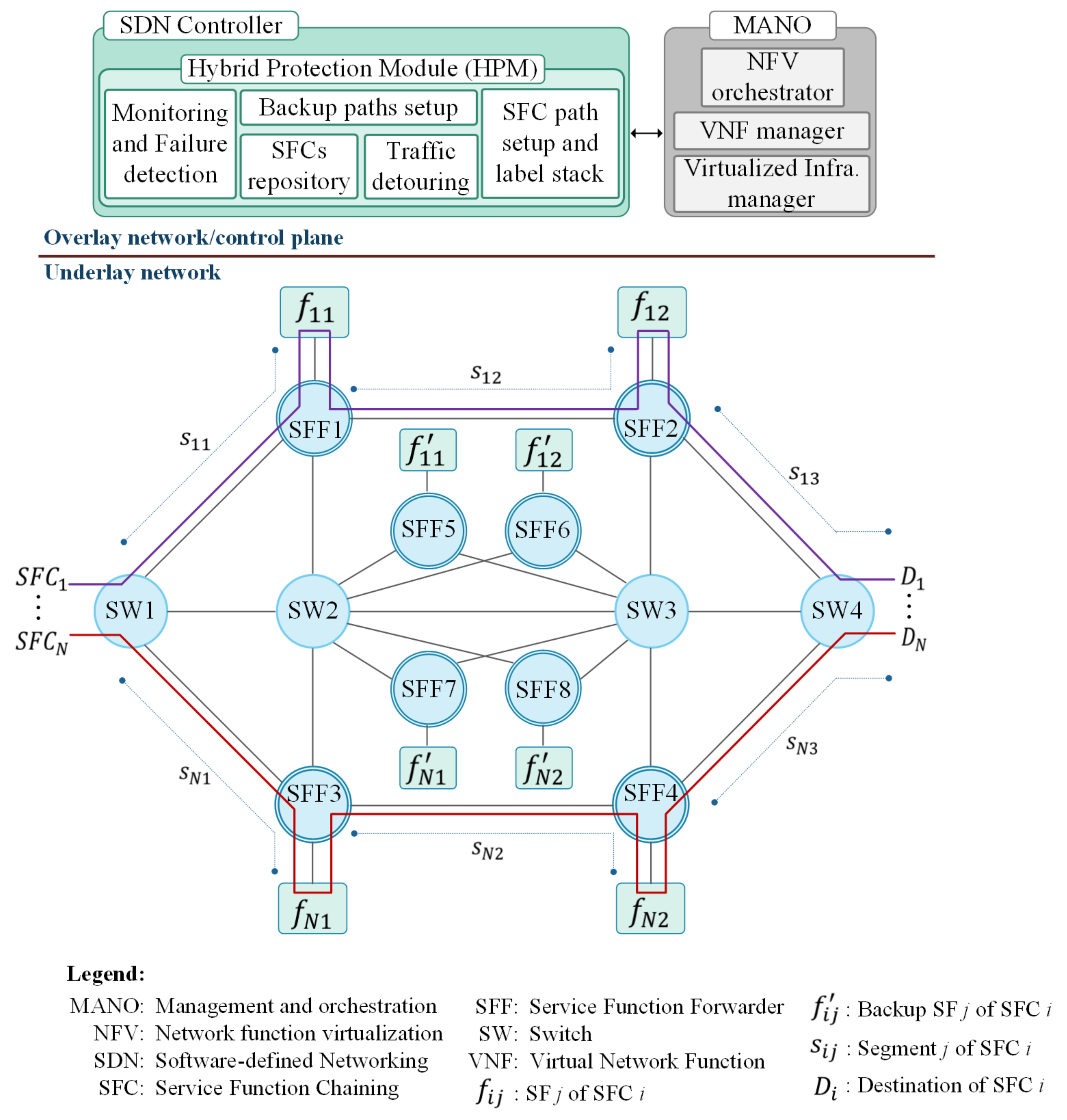
3.1. System Model and Architecture

The proposed protection mechanism uses SR to design primary routing through SFC and backup paths in the underlay network for traffic detouring after the failure has occurred in S F C i S F C , where S F C = { S F C 1 , S F C 2 , , S F C i , , S F C N } . Each element in S F C is a set of ordered SFs, S F C i = { f i 1 , f i 2 , , f i j , , f i M } . A Hybrid Protection Module (HPM) was added to the SDN controller to determine the segments S i = { s i 1 , s i 2 , , s i j , , s i ( M + 1 ) } of newly established S F C i . Segments { s i 1 , , s i M } represent the corresponding SFs { f i 1 , , f i M } , and s i ( M + 1 ) represents the last segment with no SF ( f i M , D i ] , where D i is the destination of S F C i . The NFVO ensures that for each f i j , a backup SF ( f i j S F C i ) is deployed in the underlay network, where S F C i = { f i 1 , f i 2 , , f i j , , f i M } . The HPM proactively calculates and adds the backup path for each segment in S i . Specifically, the backup path for s i j S i consists of the shortest path from f i ( j 1 ) to f i ( j + 1 ) via f i j .
SR requires an additional header in a packet, which contains ordered labels in a stack L i , where L i = { l i 1 , l i 2 , , l i j , , l i M } . Label l i j represents a corresponding SF f i j , and traffic steering through S F C i is performed based on L i . As a label represents a single SF, therefore L i = { l i 1 , l i 2 , , l i j , , l i M } represents the ordered label stack for backup SFs in S F C i . In conventional SFC, a dedicated classifier at the ingress edge of the underlay network classifies an incoming packet to a particular SFC and adds the NSH header. HP-SFC does not require a dedicated classifier, but instead uses ingress switch to classify the incoming packet based on the rules provided by the HPM and adds the MPLS header with the ordered labels’ stack. In particular, the proposed HP-SFC handles the path creation in the underlay network after the placement of primary SFs and sets up the hybrid protection mechanism for SFC after the placement of backup SFs. Therefore, the creation of the VNF-FG and its embedding into the underlay network concerning the placement of SFs were out of the scope of this paper, and this is shown by the grey-colored MANO modules in Figure 2.
The primary objectives of HP-SFC compared to conventional detouring methods in SFC are: (1) proactively calculate and store backup paths to eliminate path calculation and installation delays; (2) reduce the number of forwarding rules needed to configure the backup path while ensuring flexibility in path selection; and (3) reduce network bandwidth consumption by minimizing the exchange of control messages between the SDN controller and switches. To achieve these objectives, the HPM calculates the shortest path for each segment in SFC and generates complete primary and backup paths. Information about these paths is stored in the HPM for later processing when a failure notification is received from the switch. To detour traffic at the time of failure, the HPM matches the received failed link information with the stored paths and then appropriately modifies the flow entries. In particular, changes in two flow entries ensure that already entered traffic in the network and future SFC traffic take the pre-installed backup path.

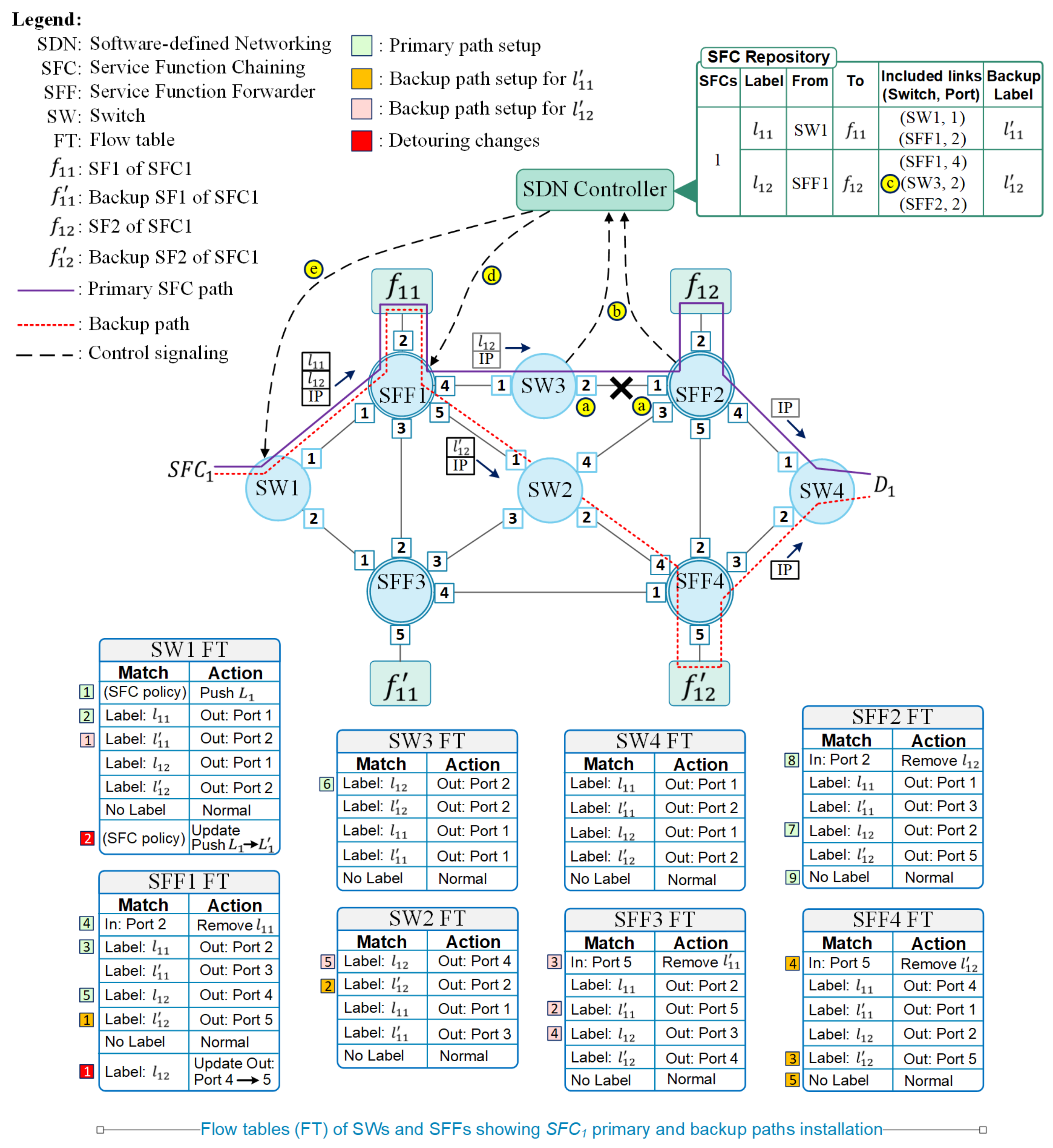
3.2. SFC Paths Installation

Multiple SF chains with different policies can function together in a network, where traffic flows belong to one of these SF chains. The match fields of flow entries in ingress switch determine the assigned SFC of an incoming packet of a particular flow. The SDN controller installs these flow entries and alters the match fields dynamically through the OpenFlow protocol, which supports up to 44 different match fields [23]. The MPLS header is added to the matched packet, and it consists of an ordered stack of labels representing the assigned SFC. Each label in the stack identifies the corresponding SF through a unique ID, and these labels are used as match fields for traffic steering through SFC. HP-SFC proposed the use of multiple labels because a single-label-based traffic steering through all the SFC increases the required flow entries and reduces the path flexibility. The NSH is an example of single-label-based traffic steering where both the SPI and SI values must be updated for traffic detouring and SPI/SI combinations increase with the increase in SFC.
The primary SFC path setup is initiated by the HPM by calculating the shortest path for s i 1 that is from the ingress switch to the SFF with which f i 1 is directly connected. In all the switches in the calculated shortest path, flow entries are installed with the match field as the top label l i 1 in the stack L i . This process is repeated for all remaining segments in S i , and its completion results in the primary path setup for S F C i . The SFF plays an important role in traffic steering through S F C i and requires three flow entries. The first flow entry in SFF has l i j of directly connected f i j as the match field and forwards the matched packets to f i j . Packets are processed at f i j and are returned to the SFF where the second flow entry pops l i j from L i . This makes l i ( j + 1 ) of f i ( j + 1 ) as the top label in L i , and the third flow entry forwards the packet towards f i ( j + 1 ) using l i ( j + 1 ) as the match field. The third flow entry in the SFF of f i M is an exception, where the destination IP is used to forward the packet towards the destination, and this is because the packet has steered through all SFs in S F C i and L i is now empty. Similarly, switches in the path for s i ( M + 1 ) use the destination IP as the match field to forward the traffic to D i .
The HPM creates the backup paths by using S F C i ; however, the process is different from primary path creation. The backup path for s i 1 consists of two parts: the first part is the shortest path from the ingress switch to the SFF connected to f i 1 , and the second part is from there to the SFF of f i 2 . The flow entry match field for switches in the first part consists of l i 1 , and in the second part, it consists of l i 2 . Similarly, the backup path for s i 2 initiates from the f i 1 SFF and terminates at the f i 3 SFF while passing through f i 2 . By repeating this process, the backup paths for each s i j in S F C i are created, and the SFFs’ functionalities remain the same as in the primary path creation. The HPM in the SDN controller stores the primary and backup paths for the SFC, as shown in Figure 3. The underlay network shown in Figure 3 consists of S F C 1 = { f 11 , f 12 } , and it is the backup S F C 1 = { f 11 , f 12 } , where Switch 1 (SW1) functions as the classifier and Switch 4 (SW4) connects to the destination. The flow tables of the SWs and SFFs in Figure 3 show the flow entries required to route traffic to the primary SFs { f 11 , f 12 } and the backup SFs { f 11 , f 12 } using their respective labels { l 11 , l 12 } and { l 11 , l 12 } . Additionally, the flow entries that are used for the primary and backup paths’ installations are indicated through numbered boxes at the side of the flow entries in Figure 3.

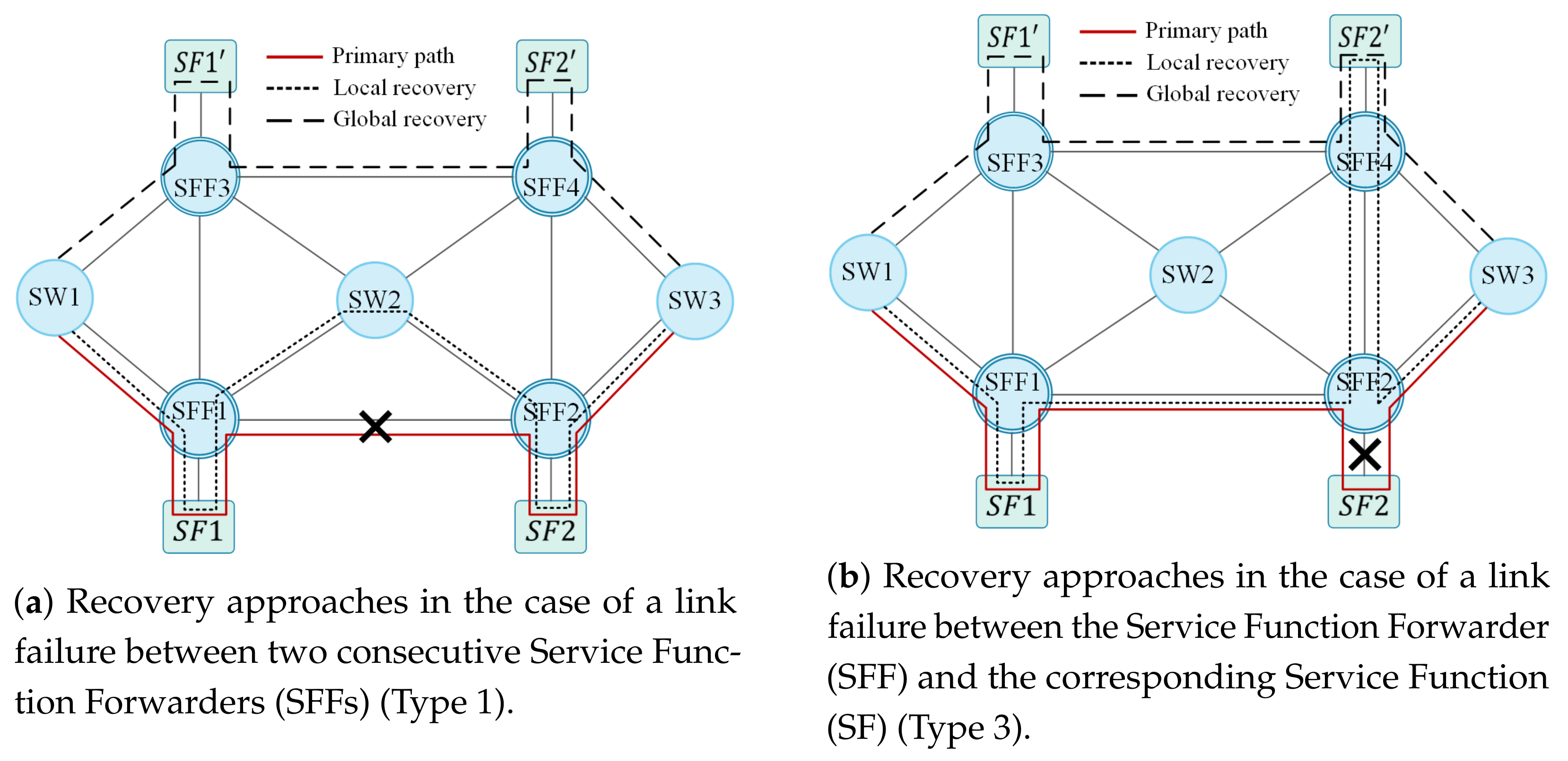
3.3. Traffic Detouring in the Case of Failure

Routing in HP-SFC is based on labels, where a single label is used within a segment (i.e., except for the last segment). A segment may consist of multiple links in the underlay network, but logically, they behave as a single link as they all use the same label to forward the traffic. This implies that failure of any link within a segment can be treated as the failure of the whole segment and requires traffic detouring around the whole segment. This approach resembles local failure recovery from the SFC perspective, albeit with one difference, which is that after bypassing the failed segment through the backup SF, the traffic is not forwarded to the starting point of the next segment. Instead, the next segment is updated with a new shortest path from the backup SF to the next SF. For example, in Figure 3, after f 12 , the traffic is forwarded to SW4 instead of SFF2. This approach also resembles global failure recovery from the segment perspective, where a completely new backup path is used.
The port down message of the OpenFlow protocol is utilized to recognize a failure in the underlay network. Switches connected on either side of the failed link detect that the status of the failed link port has changed to down ⓐ and send a port down message to the SDN controller ⓑ. The HPM receives the port down messages and extracts the switch and port IDs from each message to identify the failed link based on the underlay network topology ⓒ. The identification of the failed link allows the HPM to determine the affected SFC S F C E = { S F C 1 , S F C 2 , , S F C k , , S F C O } and its failed segments by going through the previously stored path information of all SFCs in the system, where S F C E S F C and O is the total number of affected SFC.
Regardless of the failure location in the segment s k j of S F C k , the whole s k j is considered to have failed, and first of all, the HPM stops traffic forwarding to s k j by updating the out port of the forwarding flow entry in the SFF of f k ( j 1 ) (i.e., the starting point of s k j ) towards the backup path ⓓ. This way, the already entered packets in the network that have label l k j of the failed segment in the label stack continue to traverse the SFC by detouring through the backup f k j . Secondly, the HPM updates the corresponding flow entry for S F C k in the classifying ingress switch by replacing the label l k j with l k j in the label stack ⓔ. Through this hybrid protection mechanism, the new incoming traffic for S F C k is traversed through the backup SF and avoids the failed segment, as shown in Figure 3.
Flow table configurations in different switches and SFFs to execute HP-SFC are also shown in Figure 3. In the example shown in Figure 3, the ingress switch is SW1, which works as a classifier and adds an MPLS header with the label stack onto incoming packets. The label stack L 1 consists of { l 1 , l 2 } , where they represent f 1 and f 2 in S F C 1 , respectively. The packet traverses from SW1 to SW4 while passing through f 1 and f 2 before the failure of s 2 , and after the failure, the packets are detoured to f 2 . The flow table configurations for traversing the packet through the S F C 1 primary path are detailed in following steps.
1
SW1 flow entry to add an MPLS header with label stack L 1 to the incoming packet;
2
SW1 flow entry to match the top label ( l 11 ) in the stack and forward the packet to SFF1;
3
SFF1 flow entry to match the top label ( l 11 ) in the stack and forward the packet to f 1 ;
4
SFF1 flow entry to remove the top label ( l 11 ) in the stack of the packet that is received back from f 1 ;
5
SFF1 flow entry to match the new top label ( l 12 ) in the stack and forward the packet towards SFF2;
6
SFF2 flow entry to match the top label ( l 12 ) in the stack and forward the packet to f 2 ;
7
SFF2 flow entry to remove the top label ( l 12 ) in the stack of the packet that is received from f 2 ;
8
SFF2 flow entry to match the destination IP of the packet and forward the packet to SW4, as there is no remaining label in the stack.
Along with the primary path setup, the flow table configurations for setting up the backup path are as follows:
1
SFF1 flow entry to match the label l 12 and forward the packet to SW2;
2
SW2 flow entry to match top label ( l 12 ) in the stack and forward the packet SFF4;
3
SFF4 flow entry to match the top label ( l 12 ) in the stack and forward the packet to f 2 ;
4
SFF4 flow entry to remove the top label ( l 12 ) in the stack of the packet that is received from f 2 ;
5
SFF4 flow entry to match the destination IP of the packet and forward the packet to SW4, as there is no remaining label in the stack.
The following are the changes in the flow table configurations that are required after the failure to detour the traffic to the backup path:
1
The action field of the SFF1 flow entry that matches label l 12 is updated to forward the packets to SW2;
2
The SW1 flow entry that adds the MPLS header is updated with the new label stack ( L 1 ) where l 12 is replaced by l 12 .
The backup path configuration and traffic detouring mechanisms of the proposed HP-SFC are limited to single-level failures. This means that HP-SFC can recover network traffic from single or multiple failures in the primary SFC path, but is unable to handle second- or third-level failures. Failures in the backup path or in the backup path of the backup path are defined as second- or third-level failures, respectively [5]. This implies that HP-SFC operates under the assumption that configured backup paths and backup SFs are always available, and their failure impedes HP-SFC operation and disrupts SFC. Making HP-SFC robust against second- and third-level failures is a separate study that requires multi-level SFC segmentation and labeling methods. Hence, the performance evaluation of HP-SFC in the subsequent section was performed for single-level failures.

4. HP-SFC Performance Analysis
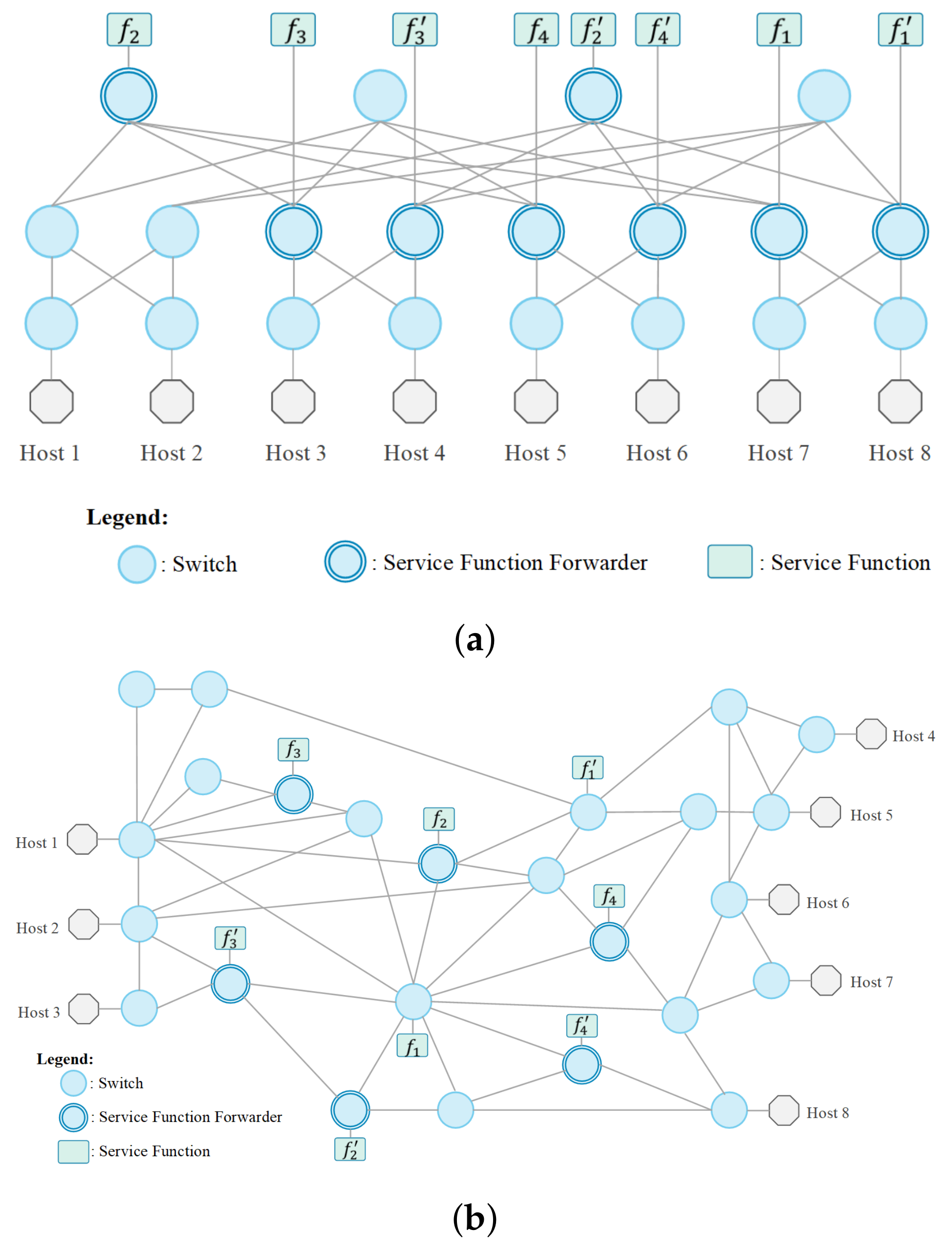
4.1. Implementation

The performance of SFC protection mechanisms is dependent on the network topology, the number of primary and backup SFs, and the placement of primary and backup SFs. In order to perform a comprehensive evaluation of HP-SFC, two network topologies were used, which are shown in Figure 4. The first topology was a three-tier fat-tree data center network with eight hosts, 20 switches, and 48 links. The second topology presented an enterprise network and was based on the AT&T backbone IP network [24] with 8 hosts, 25 switches, and 52 links. These topologies were selected because most of the SFC use-cases and deployments were in data center and enterprise networks [25,26], and their implementation for HP-SFC evaluation was carried out using Mininet [27]. Links in emulated Mininet topologies were configured with a 100 Mbps bandwidth and 1ms delay, and they were controlled by the RYU SDN controller framework v4.30. The HPM was implemented in the SDN controller for the setup and protection of SFC in the emulated topologies.
Placement of SFs in the emulated topologies was performed randomly. Four switches in each topology were randomly selected to be the SFF, and four hosts representing the SFs were added and linked with the selected SFF individually. Backup SFs for the four primary SFs were placed in a way that the disjoint path was available to access them, and Figure 4a,b shows the placement of the primary and backup SFs in each topology. Eight distinct SF chains were configured in each topology by using different combinations of primary SFs, and their details are presented in Table 1. Primary and backup paths based on the HP-SFC, local recovery, and global recovery schemes were installed for each SF chain in both topologies at the time of network initialization. Traffic for SFC was generated by the respective source hosts through the IPerf tool, and the controller utilized the ingress switches as classifiers to add label stacks to packets through MPLS headers. The controller and the emulated topologies in Mininet 2.3.0 were deployed in a system consisting of an Intel core i7 CPU @ 3.40 GHz and 32 GB memory, and the experiment results were logged for performance evaluation.

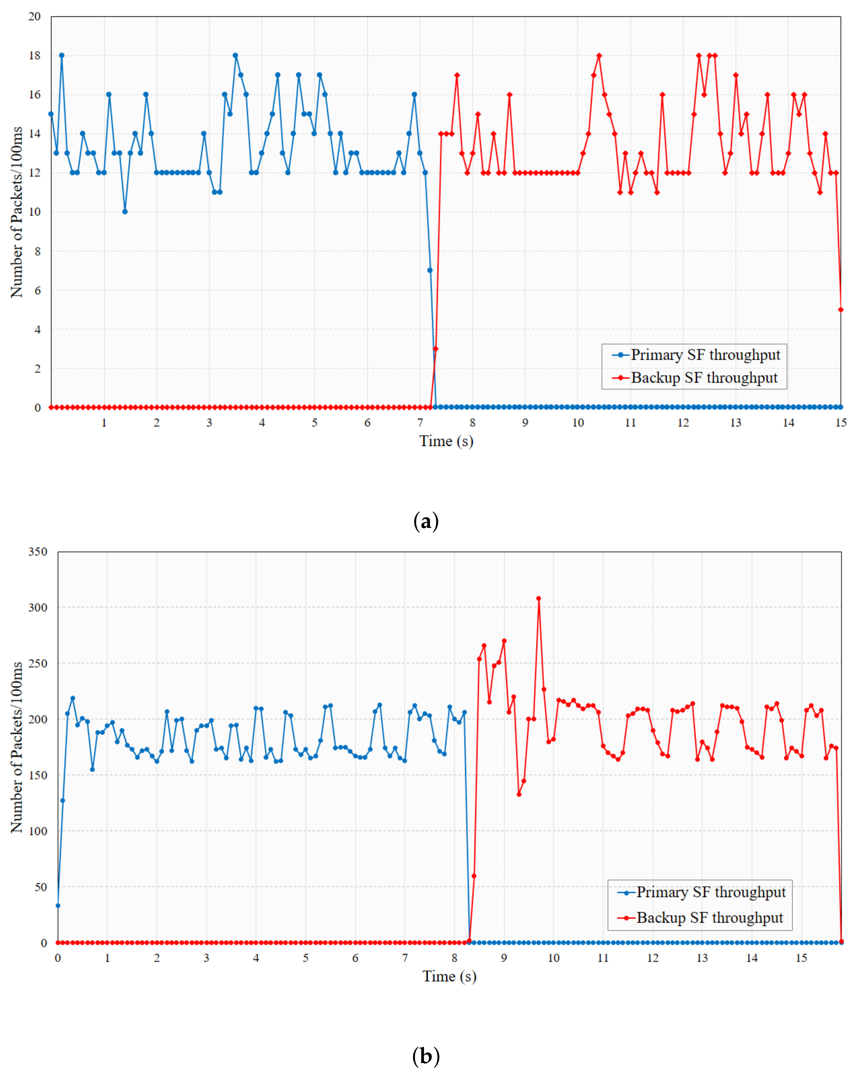
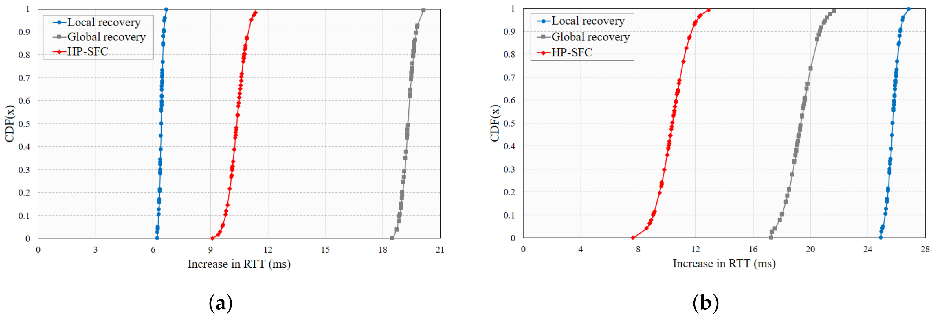
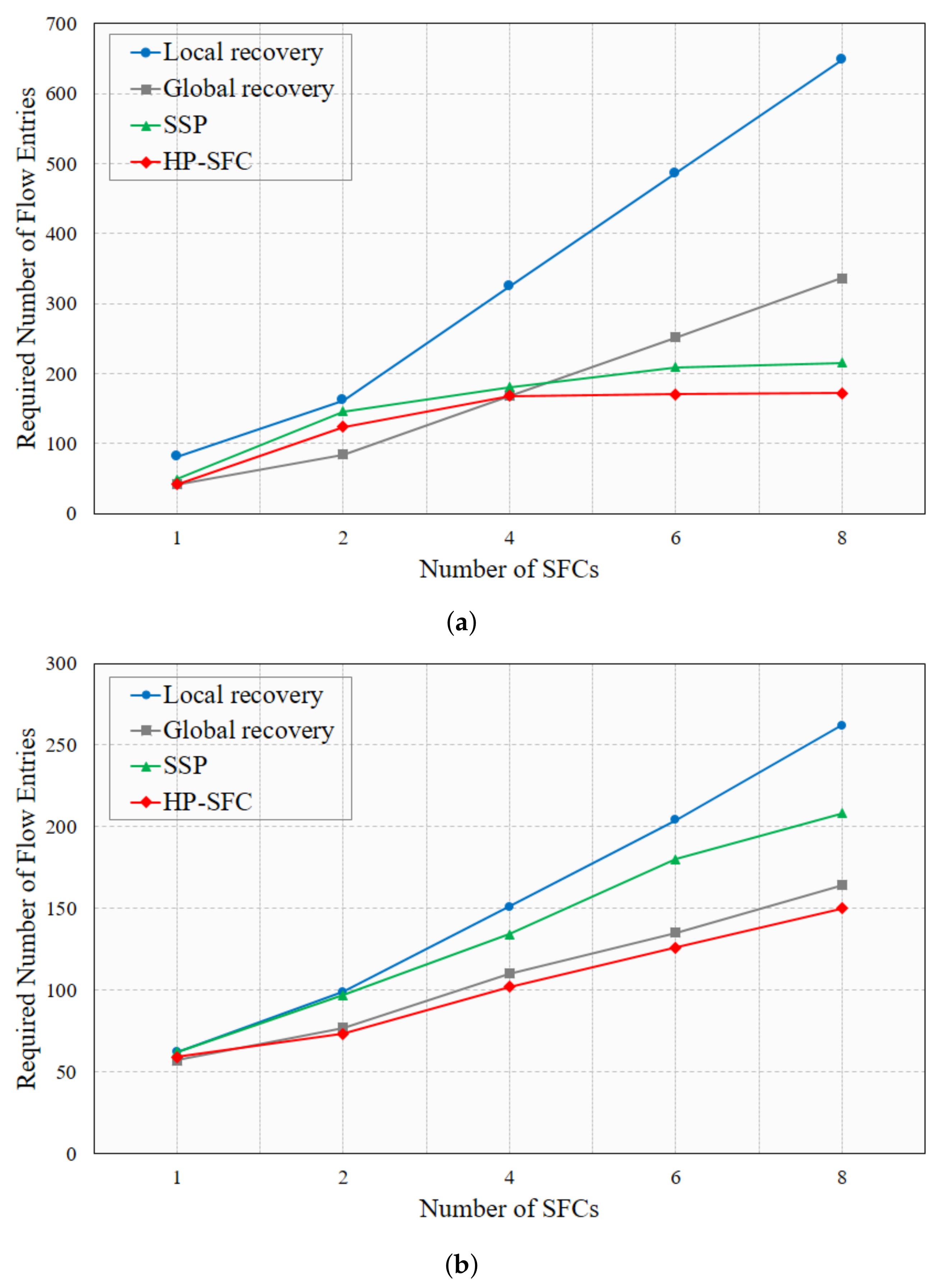
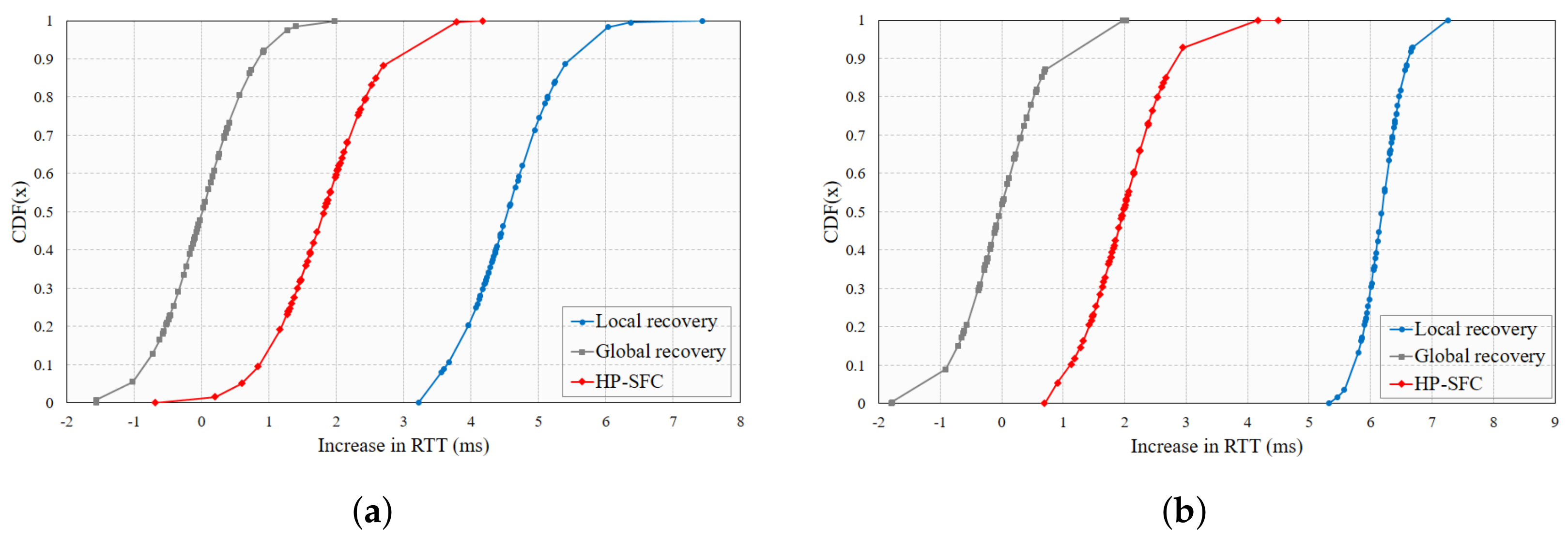
4.2. Results and Evaluation

The merits of HP-SFC were evaluated through a comparison against local and global recovery methods, which were implemented as per the details in Section 2.3. All three methods rerouted the network traffic to the respective backup paths when a failure occurred in SFC. To maintain QoS, it was necessary for the SFC protection mechanism to reroute traffic within 50 ms, which is a standard requirement in carrier networks for telephony services, and for future 5G services, this requirement is even more stringent. Traffic rerouting delay for HP-SFC was measured by initiating the emulated topologies with only SF Chain 1 and failing a link in its path. The HPM detected the failure and rerouted the traffic to the pre-installed backup path. The process of failure detection and rerouting traffic was the same for the local and global recovery mechanisms as well; therefore, traffic rerouting delay was measured only for HP-SFC.
Throughput at f 1 and f 1 in the data center and enterprise topologies is shown in Figure 5a,b, respectively. In the case of the data center topology in Figure 5a, link failure occurred at around 7.3 s, and primary SF ( f 1 ) throughput dropped to zero. At the same time, backup SF ( f 1 ) throughput increased, and the time difference between the last packet at f 1 and the first packet at f 1 was approximately 20 ms. Link failure in the enterprise topology happened at around 8.2 s, and it took roughly 25 ms for the throughput of f 1 to increase. This additional delay of 5 ms for the enterprise topology was due to a much longer backup path. This showed that the recovery delay performance of the protection mechanism could vary depending on which segment failed and where the backup was located. However, repeated experiments with the same segment failure under the same emulated environment showed a slight variation of 2∼3 ms. Regardless of the topology and placement of SFs, it can be stated based on the results in Figure 5 that HP-SFC recovered the network traffic within the industry standard of 50 ms. Moreover, the parallel flow modification messages from the controller to update the output port in the SFF of f k ( j 1 ) and label the stack in the ingress switch reduced the rerouting delay by 2.4 ms on average in comparison to our previous work [11], which sent modification messages in series.
The SFC protection mechanisms required the installation of backup paths along with the primary path setup. This resulted in unavailing occupation of precious flow table resources in switches, which caused flow table overflows and increased table miss occurrences. In addition to existing flow entries curtailing solutions [28], a practical SFC protection mechanism efficiently uses the flow table resources by reducing the flow entries for backup path setup. As traffic routing in SFC is based on labels, all the flows belonging to a single SF chain require a single flow entry in a switch for routing. However, conventional SFC traffic routing schemes use techniques that assign labels per SFC. This causes the flow entries to rapidly increase with the increase in SF chains and puts a limit on offered services and their scalability. On the contrary, the number of SFs only increases when a new feature or service is offered, which does not happen too often in service-provider networks. The proposed HP-SFC exploited this characteristic by assigning a label per SF to use flow table resources more efficiently.
Comparisons of flow table resource utilization of local recovery, global recovery, the proposed HP-SFC, and Segment-based SFP Protection (SSP) [29] in the data center topology and enterprise topology are presented in Figure 6a,b, respectively. The process and number of flow entries required for primary path setup are different in SSP than HP-SFC, local recovery, and global recovery; hence, the results in Figure 6 only compare the required number of flow entries to setup backup paths. The local recovery method showed almost a linear increment in the required number of flow entries for both topologies, because it installed a backup path for every link in the primary SFC path. Similarly, the global recovery method showed an increment in the required number of flow entries for backup paths, but its slope was much lower than the local recovery method. HP-SFC not only required a much lower number of flow entries, but also showed no increment after four SF chains in Figure 6a. This was because all the switches involved in the backup paths already had flow entries related to the labels of all backup SFs, and no new entries were required. In Figure 6b, the required number of flow entries by HP-SFC continued to increase with the increase in SF chains because the enterprise topology had more switches and links and different backup paths used different switches and links. Once all the switches in the enterprise topology had entries for all the backup SFs labels, then there would be no increment in the required flow table entries, as in the data center topology. SSP followed the same increment trend as HP-SFC, but required 22% and 32% more flow entries than HP-SFC in the data center and enterprise topologies with eight SF chains, respectively. This was because SSP used both labels and input ports to define the flow entries that caused the installation of multiple flow entries for the same label packets from different ports. Consequently, SSP used more flow table resources to install backup paths than the proposed HP-SFC.
Network traffic detouring to the backup path caused the end-to-end transmission delay to increase, where the amount of delay added depended on the SFC protection mechanism. To compare the performance of local recovery, global recovery, and HP-SFC in terms of transmission delay, we initialized the data center and enterprise topologies with SF Chains 1, 3, and 8 and failed a SFF-SFF link that was shared among them. This caused each protection mechanism to reroute traffic to a pre-installed backup mechanism, and for each protection mechanism, the average difference in the Round Trip Time (RTT) for three SF chains was measured. Through a similar process, the average RTT increase of the three SF chains in both topologies was measured when the shared SFF-SF link had failed.
The results of the RTT increment in the data center topology for SFF-SFF and SF-SFF failed links are shown in Figure 7a,b, respectively. The composition of the data center topology was such that there were multiple shortest paths available, but providing a backup path for a single link requires traffic detouring through various links. For these reasons, global recovery showed the lowest RTT increment and local recovery the highest RTT increment in Figure 7a,b. In HP-SFC, the whole segment was viewed as failed for either SFF-SFF link failure or SF-SFF link failure, and this enabled it to detour traffic with few additional links and provide a more consistent protection performance, as shown in Figure 7a,b. On the contrary, the composition of the enterprise topology was much different than the data center topology, where a few densely connected switches provided multiple routes, however, there were only a few end-to-end shortest paths. This topology composition caused the results of local recovery and global recovery to vary dramatically for the SFF-SFF link failure and SF-SFF link failure cases in Figure 8a,b, whereas HP-SFC again showed more consistent results and had the lowest RTT increment in the case of SF-SFF failure in Figure 8b. Based on the results in Figure 7 and Figure 8, it can be concluded that HP-SFC might not always provide the lowest RTT increment, but its performance was more consistent and reliable in comparison to local and global recoveries.

5. Conclusions and Future Improvements

A novel HP-SFC protection mechanism was proposed in this manuscript, which focused on efficient network traffic rerouting in SFC when a failure occurred. HP-SFC was designed based on the segment routing technique, where SF chains were divided into segments and backup paths established for each segment using the backup SFs. Any failure in a segment was taken as a failure of the whole segment, and traffic was detoured to a pre-installed backup path from the initial point of the failed segment. The results showed that HP-SFC recovered traffic within 50 ms, which is an industry standard. These results were made possible by the segmentation technique, which reused the already established primary path, similar to local recovery, and required only three flow entry update messages to detour the traffic. Another benefit of using the segmentation technique was a more stable and consistent performance in terms of the RTT increment due to traffic detouring, as shown by the results. Moreover, for traffic steering in SFC, a new label stacking mechanism was proposed in this paper that was not limited to the protection mechanism and could also be used for other traffic engineering purposes in SFC. This mechanism labeled SFs instead of SF chains and stacked these labels in the order of SFs in a particular SF chain before adding it as the MPLS header in a packet. The results showed that it not only reduced the footprint of flow entries’ usage by HP-SFC, but also solved the scaling problem with the massively increasing number of SF chains in the network. The results clearly showed that the performance of HP-SFC and other protection mechanisms was intrinsically dependent on the composition of the network topology, which is a major limitation. Currently, we are working to reduce this limitation by integrating HP-SFC with the delay- and availability-aware placement of exclusive and shared backup SFs in the network. In the next step, we will aim to make HP-SFC robust against second- and third-level failures through a multi-level labeling approach that encapsulates the information of multiple labels in a single label.

Author Contributions

Conceptualization, S.M.R. and H.C.; methodology, S.M.R., M.K., and H.J.; software, H.J.; validation, H.C., M.K., and S.M.R.; formal analysis, H.C. and M.K.; visualization, S.M.R.; writing—original draft preparation, S.M.R. and H.J.; writing—review and editing, M.K. and H.C.; supervision, H.C. and M.K. All authors read and agreed to the published version of the manuscript.

Funding

This work was partly supported by the Ministry of Education, Institute of Information and Communications Technology Planning and Evaluation (IITP), and the National Research Foundation (NRF), Korea, under the GITRC support program (IITP-2021-2015-0-00742), the ICT Creative Consilience program (IITP-2021-2020-0-01821), and the mid-career support program (NRF-2020R1A2C2008447).

Institutional Review Board Statement

Not applicable.

Informed Consent Statement

Not applicable.

Data Availability Statement

All the data generated during the experiments are presented in the article.

Conflicts of Interest

The authors declare no conflict of interest.

References

  1. Challa, R.; Zalyubovskiy, V.V.; Raza, S.M.; Choo, H.; De, A. Network Slice Admission Model: Tradeoff Between Monetization and Rejections. IEEE Syst. J. 2020, 14, 657–660. [Google Scholar] [CrossRef]
  2. Lee, D.; Raza, S.M.; Kim, M.; Choo, H. Cost Effective Control Plane Design for Service Assurance in Software Defined Service Function Chaining. In Future Data and Security Engineering. Big Data, Security and Privacy, Smart City and Industry 4.0 Applications; Dang, T.K., Küng, J., Takizawa, M., Chung, T.M., Eds.; Springer: Singapore, 2020; pp. 387–400. [Google Scholar]
  3. Cisco. White Paper: Cisco Annual Internet Report (2018–2023). Available online: https://www.cisco.com/c/en/us/solutions/collateral/executive-perspectives/annual-internet-report/white-paper-c11-741490.pdf (accessed on 20 March 2021).
  4. Thorat, P.; Raza, S.M.; Kim, D.S.; Choo, H. Rapid recovery from link failures in software-defined networks. J. Commun. Netw. 2017, 19, 648–665. [Google Scholar] [CrossRef]
  5. Thorat, P.; Jeon, S.; Raza, S.M.; Challa, R.; Choo, H. Scalable and Efficient Forwarding Table Design for Multi-Link Failover in OpenFlow-Enabled Networks. IETE Tech. Rev. 2017, 34, 27–38. [Google Scholar] [CrossRef]
  6. Soualah, O.; Mechtri, M.; Ghribi, C.; Zeghlache, D. A link failure recovery algorithm for Virtual Network Function chaining. In Proceedings of the 2017 IFIP/IEEE Symposium on Integrated Network and Service Management (IM), Lisbon, Portugal, 8–12 May 2017; pp. 213–221. [Google Scholar] [CrossRef]
  7. Rahman, M.R.; Boutaba, R. SVNE: Survivable Virtual Network Embedding Algorithms for Network Virtualization. IEEE Trans. Netw. Serv. Manag. 2013, 10, 105–118. [Google Scholar] [CrossRef]
  8. Filsfils, C.; Previdi, S.; Ginsberg, L.; Decraene, B.; Litkowski, S.; Shakir, R. Segment Routing Architecture. RFC 8402 2018. [Google Scholar] [CrossRef]
  9. Yu, H.; Anand, V.; Qiao, C.; Sun, G. Cost Efficient Design of Survivable Virtual Infrastructure to Recover from Facility Node Failures. In Proceedings of the 2011 IEEE International Conference on Communications (ICC), Kyoto, Japan, 5–9 June 2011; pp. 1–6. [Google Scholar] [CrossRef]
  10. Ayoubi, S.; Chen, Y.; Assi, C. Towards Promoting Backup-Sharing in Survivable Virtual Network Design. IEEE/ACM Trans. Netw. 2016, 24, 3218–3231. [Google Scholar] [CrossRef]
  11. Jeong, H.; Raza, S.M.; Tien Nguyen, D.; Kim, S.; Kim, M.; Choo, H. Control Plane Design for Failure Protection in Software Defined Service Function Chains. In Proceedings of the 2020 14th International Conference on Ubiquitous Information Management and Communication (IMCOM), Taichung, Taiwan, 3–5 January 2020; pp. 1–6. [Google Scholar] [CrossRef]
  12. ETSI. Network Functions Virtualisation (NFV); Architectural Framework; GS NFV 002 v1.2.1; 2014. [Google Scholar] [CrossRef]
  13. Mijumbi, R.; Serrat, J.; Gorricho, J.; Latre, S.; Charalambides, M.; Lopez, D. Management and orchestration challenges in network functions virtualization. IEEE Commun. Mag. 2016, 54, 98–105. [Google Scholar] [CrossRef]
  14. Dan, L.; Julong, L.; Yuxiang, H. Central Control over Distributed Service Function Path. KSII Trans. Internet Inf. Syst. 2020, 14, 577–594. [Google Scholar] [CrossRef]
  15. Quinn, P.; Elzur, U.; Pignataro, C. Network Service Header (NSH). RFC 8300 2018. [Google Scholar] [CrossRef]
  16. Scholl, T.; Mullooly, J.; Smith, D.; Jaeger, W. Label Edge Router Forwarding of IPv4 Option Packets. RFC 6178 2011. [Google Scholar] [CrossRef] [Green Version]
  17. Gill, P.; Jain, N.; Nagappan, N. Understanding Network Failures in Data Centers: Measurement, Analysis, and Implications. SIGCOMM Comput. Commun. Rev. 2011, 41, 350–361. [Google Scholar] [CrossRef]
  18. Kong, J.; Kim, I.; Wang, X.; Zhang, Q.; Cankaya, H.C.; Xie, W.; Ikeuchi, T.; Jue, J.P. Guaranteed-Availability Network Function Virtualization with Network Protection and VNF Replication. In Proceedings of the GLOBECOM 2017—2017 IEEE Global Communications Conference, Singapore, 4–8 December 2017; pp. 1–6. [Google Scholar] [CrossRef]
  19. Abdelsalam, A.; Clad, F.; Filsfils, C.; Salsano, S.; Siracusano, G.; Veltri, L. Implementation of virtual network function chaining through segment routing in a linux-based NFV infrastructure. In Proceedings of the 2017 IEEE Conference on Network Softwarization (NetSoft), Bologna, Italy, 3–7 July 2017; pp. 1–5. [Google Scholar] [CrossRef] [Green Version]
  20. Giorgetti, A.; Sgambelluri, A.; Paolucci, F.; Cugini, F.; Castoldi, P. Segment routing for effective recovery and multi-domain traffic engineering. IEEE/OSA J. Opt. Commun. Netw. 2017, 9, A223–A232. [Google Scholar] [CrossRef]
  21. Thorat, P.; Jeon, S.; Choo, H. Enhanced local detouring mechanisms for rapid and lightweight failure recovery in OpenFlow networks. Comput. Commun. 2017, 108, 78–93. [Google Scholar] [CrossRef]
  22. Ko, K.; Son, D.; Hyun, J.; Li, J.; Han, Y.; Hong, J.W. Dynamic failover for SDN-based virtual networks. In Proceedings of the 2017 IEEE Conference on Network Softwarization (NetSoft), Bologna, Italy, 3–7 July 2017; pp. 1–5. [Google Scholar] [CrossRef]
  23. Open Network Foundation. OpenFlow Switch Specification Version 1.5.1. TS-025. 2015. Available online: https://opennetworking.org/wp-content/uploads/2014/10/openflow-switch-v1.5.1.pdf (accessed on 4 June 2012).
  24. Knight, S.; Nguyen, H.X.; Falkner, N.; Bowden, R.; Roughan, M. The Internet Topology Zoo. IEEE J. Sel. Areas Commun. 2011, 29, 1765–1775. [Google Scholar] [CrossRef]
  25. Kumar, S.; Tufail, M.; Majee, S.; Captari, C.; Homma, S. Service Function Chaining Use Cases In Data Centers. Internet-Draft draft-ietf-sfc-dc-use-cases-06, Internet Engineering Task Force, 2017. Work in Progress. Available online: https://datatracker.ietf.org/doc/html/draft-ietf-sfc-dc-use-cases (accessed on 4 June 2021).
  26. Wang, E.; Leung, K.; Felix, J.; Iyer, J.; Patel, P. Service Function Chaining Use Cases for Network Security. Internet-Draft draft-wang-sfc-ns-use-cases-03, Internet Engineering Task Force, 2017. Work in Progress. Available online: https://datatracker.ietf.org/doc/html/draft-wang-sfc-ns-use-cases-03 (accessed on 4 June 2021).
  27. Xiang, Z.; Seeling, P. Chapter 11—Mininet: An instant virtual network on your computer. In Computing in Communication Networks; Fitzek, F.H., Granelli, F., Seeling, P., Eds.; Academic Press: Cambridge, MA, USA, 2020; pp. 219–230. [Google Scholar] [CrossRef]
  28. Jian, S.; Ruoyu, X.; ShiMing, Y.; BaoWei, W.; Jiuru, W. Redundant rule Detection for Software-Defined Networking. KSII Trans. Internet Inf. Syst. 2020, 14, 2735–2751. [Google Scholar] [CrossRef]
  29. Thorat, P.; Dubey, N.K. Pre-provisioning Protection for Faster Failure Recovery in Service Function Chaining. In Proceedings of the 2020 IEEE International Conference on Electronics, Computing and Communication Technologies (CONECCT), Bangalore, India, 2–4 July 2020; pp. 1–6. [Google Scholar] [CrossRef]
Figure 1. Local and global recovery for link failure (a) in the path between consecutive SFFs and (b) between the SFF and SF.
Applsci 11 05245 g001
Figure 2. HP-SFC overlay and underlay networks’ architecture and system model.
Applsci 11 05245 g002
Figure 3. Traffic detouring example for SFC in the proposed hybrid protection mechanism and the flow tables’ configurations for the primary path, backup path, and traffic detouring in the case of failure.
Applsci 11 05245 g003
Figure 4. Emulated network topologies in Mininet for the performance evaluation of SFC protection mechanisms. (a) Emulated three-layer fat-tree data center topology. (b) Emulated enterprise network topology based on the AT&T IP backbone network [24].
Applsci 11 05245 g004
Figure 5. Network traffic recovery delay for single SF chain incurred by HP-SFC in the data center and enterprise topologies. (a) Throughput at the primary SF ( f 1 ) and backup SF ( f 1 ) in the data center topology. (b) Throughput at the primary SF ( f 1 ) and backup SF ( f 1 ) in the enterprise topology.
Applsci 11 05245 g005
Figure 6. Flow table resource utilization comparison of local recovery, global recovery, SSP, and HP-SFC in the data center and enterprise topologies. (a) Flow table resources utilized in the data center topology by backup paths. (b) Flow table resources utilized in the enterprise topology by backup paths.
Applsci 11 05245 g006
Figure 7. Data center topology, average RTT increment of SFCs 1, 2, and 9 for local recovery, global recovery, and HP-SFC protection mechanisms. (a) RTT increment for SFF-SFF link failure. (b) RTT increment for SF-SFF link failure.
Applsci 11 05245 g007
Figure 8. Enterprise topology, average RTT increment of SFCs 1, 3, and 8 for local recovery, global recovery, and HP-SFC protection mechanisms. (a) RTT increment for SFF-SFF link failure. (b) RTT increment for SF-SFF link failure.
Applsci 11 05245 g008
Table 1. Details of the configured SFC in the emulated topologies.
Source HostOrdered Service FunctionsDestination Host
SFC1Host 1SF1Host 8
SFC2Host 8SF1 → SF2 → SF3Host 3
SFC3Host 7SF1 → SF2Host 1
SFC4Host 4SF2 → SF4Host 6
SFC5Host 3SF3Host 2
SFC6Host 2SF2 → SF3 → SF4Host 5
SFC7Host 2SF2 → SF3Host 4
SFC8Host 3SF3 → SF1Host 7
Publisher’s Note: MDPI stays neutral with regard to jurisdictional claims in published maps and institutional affiliations.

