1. Introduction
This paper presents an overview of the activities and construction works that were undertaken from 2015 to 2020, aimed at repair and foundation strengthening of the towers of Cathedral of St. Theresa of Avila in Subotica. During this time, two major attempts were made in order to stop the slow, but persistent, differential settlements of the towers. These settlements were observed since the erection of the towers and continue to this day. The first repair attempt consisted of jacked-in-piles beneath the towers, and the second attempt consisted of soil injections of the polyurethane, expansive, resin (PU resin) beneath the towers and the surrounding area. Unfortunately, both attempts failed to stop the settlements and damages to the structure are still present, leading to the new repair proposal.
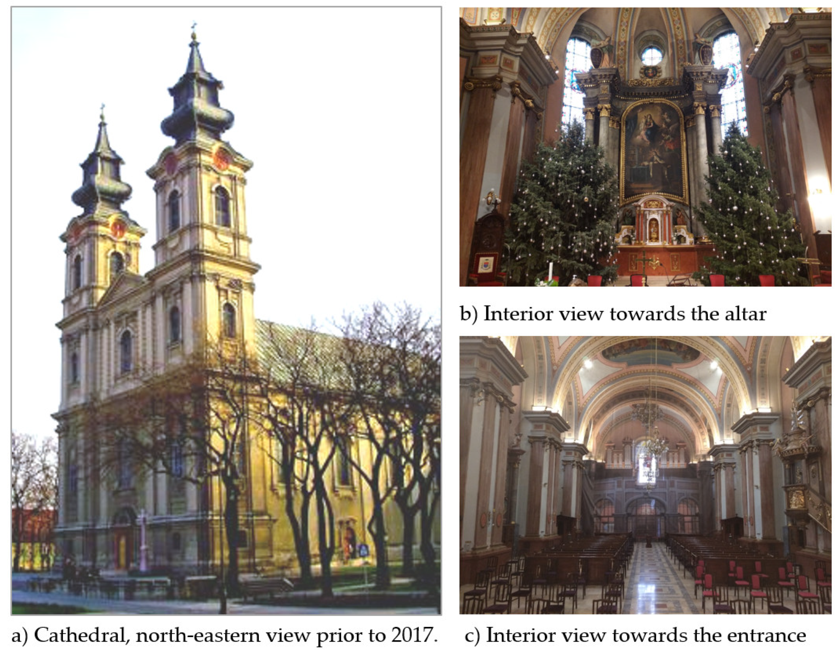
The Cathedral is east-west oriented,
Figure 1. The total length is 61 m, the width of the nave is 21 m, the ridge is 28 m high, and the height of the tower is 54 m. In terms of constructive and decorative elements, regarding the shape of arches and plastic treatment of the facades, the Cathedral has properties of a transitional Baroque-Classicist style. Two tall monumental towers face east and lavishly decorated portal between them is crowned by a tympanum with the sculpture of the Virgin Mary on top of it. The verticality of the building is emphasized by multi-profiled pilasters, which are doubled at the edge of the bell tower and simple on the ground floor; on the first floor, there are ionic capitals, below which the garland descends, and on the second floor there are Corinthian capitals. The windows in the fields are elongated with characteristic, unpretentious, baroque plastic. The façade is horizontally divided into three segments. Above the entrance portal, there are two vertical, arched, openings. The bell towers on the ground floor have rectangular openings, and above them there are two semi-circular arched windows. The rest of the building is less imposing. Simply profiled pilasters are rhythmically arranged along the wall canvas, between which there are arched windows. Above the elevated part of the altar is a crypt, and on the side, there are semi-circular sacristies and a chapel.
According to historical data, the Cathedral of St. Theresa of Avila in Subotica was built from 1773 to 1798. The works began according to the project of the Pest master mason Ferenc Kaufman, to be completed according to the project of Adam Heisler in 1783. It was built on compressible clay soil, on a site bordered by swampy troughs. From the east side, in the north-south direction, a stream flowed until the end of the 19th century, through which water flowed from the nearby shallow lake “Jasi-bara”. Construction proceeded slowly with frequent changes to the project, only to be suspended in 1779, and resumed in 1787 to 1789. The interior decoration was completed in 1803, and the copper roof covering of the towers, which replaced the dilapidated wooden shingles, in 1839. Historic archive data show that the construction of the building was constantly accompanied by settlements, cracks and damage to the arches and vaults, which were repaired several times. A newspaper article from 1879 describes the cracks that spread from the foundation to the roof of the facade, as well as cracks in the vaults of the nave. Partial renovation of the altar was carried out in 1888 by replacing the old sacristies with larger semi-circular sacristies with vestibule, staircase, and a small chapel, stiffening and stabilizing the nave arches in the altar region.
The problem of cracks in the frontage remained relevant and attracted the attention of eminent experts of the time, from Subotica, Pest, and Vienna. Professor Csaki Bella from Budapest wrote in 2009 in his “Study on the assessment of the condition of the Basilica of St. Theresa of Avila” [
1] about the restoration by the engineer Toth Mihaly in 1876, who used iron ties. As he further states, due to very large horizontal forces, the ties stretched significantly and were unable to prevent the tilting of the towers and the crack growth. A similar idea, with ties, was given in 1883 by the famous Hungarian architect of that time, Geza Ziegler. Traces of attempts to solve the problem of the towers tilting and the crack growth in the frontage wall are still visible today. Out of the nine ties, placed about 150 years ago, seven are broken and the remaining two are overly stretched and dysfunctional. According to the writings of engineer Tot Mihaly, during 1886 to 1877 observations, cracks were measured but appropriate conclusions about the causes could not be formed in such a short time. It was only six years later that a group of prominent experts at the time—Pal Karvayi, Titus Macskovic, Istvan Grundbok and Geza Kocka—came to the correct conclusion that the crack growth in the frontage was the result of very slow and uneven settlements and tilting of towers on soft ground.
The last major intervention in the Cathedral lasted from 1909 to 1912 and included the restoration of the outer facade with “Terranova” mortar. However, after a few years, cracks reappeared, so the problem remained relevant throughout the 20th century, without any measures being taken to repair them. The restoration of the facade was completed in 1912, and since there were no major interventions since, it can be concluded that the current total width of cracks in the crown of the frontage wall of about 15 cm is the result of uneven settlement of the towers in the past 105 years. In 2015, a decision was made to start planning a rehabilitation of the Cathedral. Based on calculations and previous experiences, the initial plan to install new ties [
2,
3,
4,
5] was rejected. In 2018, an attempt was made to reduce the soil angular pressure by jacked-in piles [
6]. However, due to the implementation technology, small, residual, successive, settlements appeared during hydraulic jack transfer from one pile to another, which, in turn, increased the crack widths. The works were halted, resulting in only 11 out of 16 piles being installed—six below the north tower and five below the south tower. The settlements partially subsided after six months. After that, according to the proposal of experts from Budapest, the soil was strengthened by injecting expansive resins [
7,
8]. These works were completed but, unfortunately, instead of stabilizing, the settlements intensified even more. Consequently, in 2019, all works were temporary halted again, while maintaining continuous monitoring of the settlements, crack widths, and in-depth analysis of other possible remediation strategies. Based on the structural monitoring and additional analyses, a new solution was formed that includes partial dismantling and reconstruction of the upper sections of the front facade wall and of the towers. Within reconstruction, a strong structural connection is planned, among the two towers, and between the towers and the nave. The emphasis is on retaining the original appearance of the Cathedral facades while creating reconstructed elements that are lighter and structurally stronger, thereby producing smaller weight and pressure on the ground, and obtaining more favorable structural behavior overall.
2. Investigative Works That Preceded the Rehabilitation
For the purpose of the rehabilitation project, in 2015, for the first time in the long history of the structure, detailed tests were conducted, which included soil investigations, excavations near existing foundations, testing of bricks and mortar within the foundation and the structure, and mapping of all cracks and damages [
5],
Figure 2,
Figure 3 and
Figure 4.
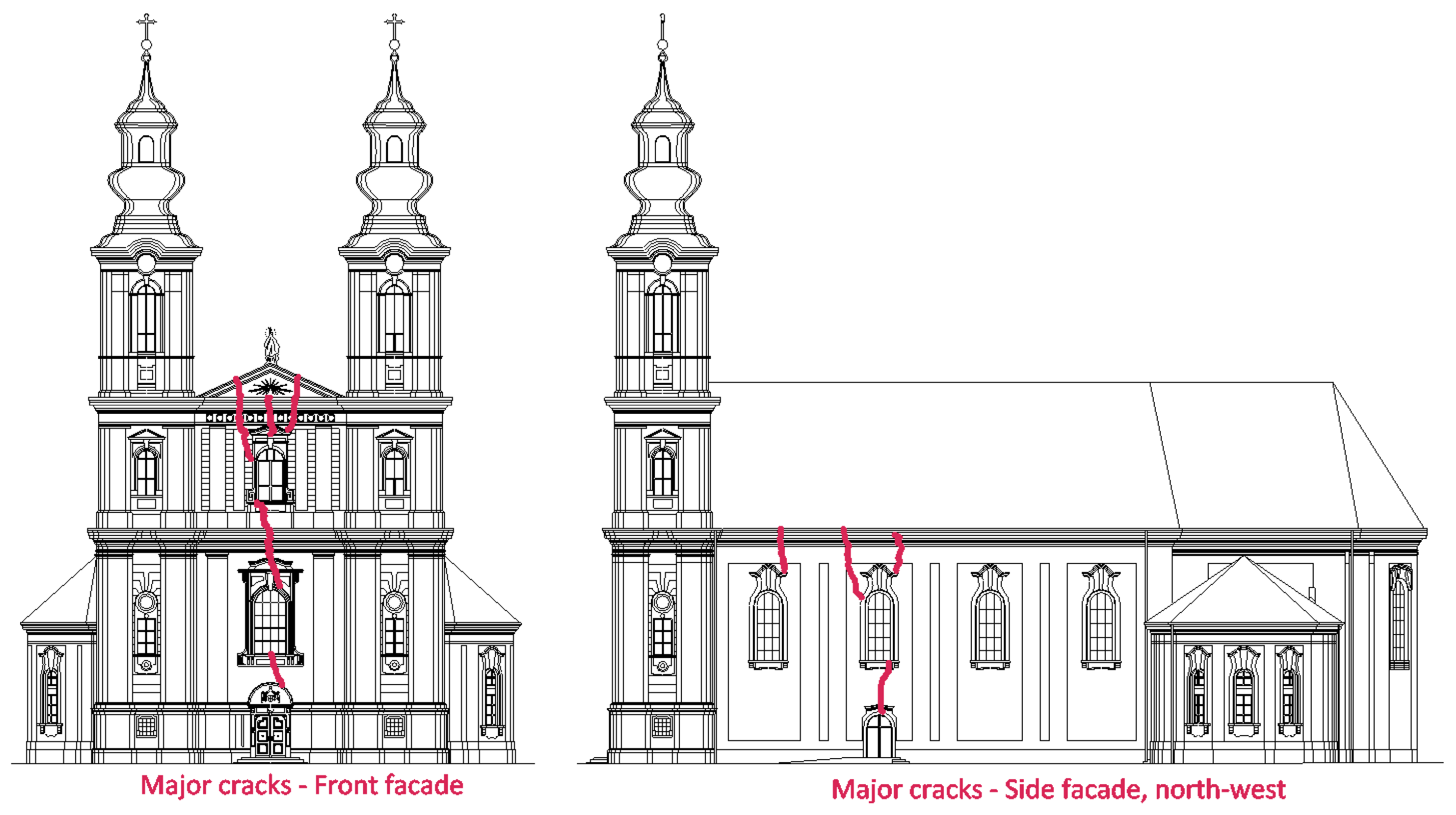
Figure 2 shows the large cracks that developed on the frontal facade. At present, these cracks have a maximum width of approximately 19 cm, and they spread over the full thickness of the wall, over the whole crack lengths.
Installation of crack meters, inclinometers, geodetic markers and measurements, and complete recording of the geometry and condition of the structure and materials of the building were made. As part of soil-mechanic tests, six static penetrations 16 to 21 m deep, and four boreholes of 15 m were made, from which samples were taken. Laboratory tests have shown that the soil profile, up to a depth of 9 m, consists of low/medium plastic soft clay (CL-CI), below which is a layer of sand (SF) 1.8 to 2 m thick (
Figure 5).
After that, clays reappear, ending above a layer of compacted sand at a depth of 18 to 20 m. According to historic data, this location in the past was bordered by swampy troughs and canals, which is indicated by the presence of muddy and marshy impurities in the upper parts of the terrain. According to limited piezometric measurements (
Figure 6), the groundwater depth is at 3.2 to 4.2 m from the ground level around the Cathedral (112.6 m MASL).
Based on the excavations, the depth of the foundation of the northern tower is approximately 2.5 m, while at the southern tower, it is at approximately 3.0 m. Testing of the bricks from the foundation wall showed that their compressive strength ranges from 1.3 to 2.0 MPa. The bottom parts, the footings, of the tower foundations have a surface of approximately 8 × 8 m, and a thickness of 2.0 m, and were made from an uneven mixture of lime concrete with sand and irregular pieces of larger and smaller bricks and sandstone rocks,
Figure 7.
Lime concrete was used in construction approximately 5000 years before cement; it is characterized by significantly lower compressive strength and greater plasticity than cement concrete. These properties make it able to withstand large and long-term deformations before cracks appear. Lime concrete is also very hygroscopic, which is why it turns into a soft mass when cut or drilled with water cooling. The strength of lime concrete used in this structure could not be tested, but based on its resistance to impact and breakage of parts, it could be concluded that it is slightly higher than the compressive strength of bricks within the structure.
It is interesting to note that, despite the significant damage to the Cathedral (
Figure 8) caused by long-lasting and uneven settlements, there are no written traces that geodetic measurements were ever performed in the previous 100 to 150 years. Except for the state markers in the front wall of the south tower, there was no other geodetic markers on the building. Therefore, for the purpose settlements monitoring of the Cathedral, about 30 new geodetic markers were installed in the outer walls and two adjacent ones on old buildings nearby. These geodetic markers form a stable and highly accurate levelling network. In order to analyse the inclination of the towers, in 2016, a geodetic measurement of the verticality of the south wall edges of the south tower and the north wall edges of the north tower was performed (
Figure 9), between elevation
H = 131 to 136 m. The +
X axis is in the south direction, and the +
Y is in the west direction. I1 and I4 are the edges of the south tower, while I2 and I3 are of the north tower [
9,
10].
Linear interpolation of observed points on the tower edges show the inclination, namely the lining I1–I4 of the south tower to the south by θX = 3.79 mm/m, and the lining I2–I3 of the north tower to the north by θX = 1.33 mm/m, or divergence of 5.12 mm/m. At the same time, both towers lean to the east about θY = 2.16–2.88 mm/m. At the height of the crown of the frontage wall at 27.0 m (elevation 137.5 m), the spacing of the towers is about ΔX = 27 × 0.512 = 13.8 cm, which is slightly less than 15 cm, which is approximately the sum of the measured cracks width at the crown of the frontage wall.
3. Analysis and Interpretation of Measurement Results
3.1. Soil Properties
Based on soil investigation, the ground at the location of the Cathedral consists of low-plastic clay which extends to a depth of about 18 to 20 m and is cut at a depth of about 9 to 9.5 m with a 1.8 to 2 m thick layer of sand. Based on laboratory tests, the compressibility of clay, at a depth between 2.5 to 5.0 m, because of the effect of pre-consolidation, reaches the highest values, of a range between 7.0 and 9.0 MPa. At other depths, the modulus is significantly smaller, between 3.1 and 4.8 MPa.
According to the analysis, the weight of the individual tower is up to V = 32.0 MN, and the height of the centre of gravity is about Zt = 15.0 m. The average pressure below the quadratic foundation footing B = 8.0 m is q = 500 kPa. When the pressure on the ground is known, the settlement of the tower can be determined through the method of one-dimensional deformation, and since the foundation is rigid, the settlement is determined by the equivalent point of the foundation.
The soil compressibility modules were adopted by the correlation with one penetration resistance, using a simplified diagram of mean values on
Figure 10. The calculated settlement is about
s = 25 cm.
For further analysis, using the calculated settlement of the tower, the average modulus of elasticity was determined by the following analytical expression [
12]:
In the above expression,
I1 = 0.8 is the embedment depth ratio,
I2 = 0.24 is the shape ratio, and
I3 = 0.07 is the layer thickness ratio. The thickness of the compressible layer is the depth at which the vertical stress from the influence of the foundation is less than 10% of the effective stress due to the self-weight of the soil. The average modulus of elasticity of a deformable layer of thickness
H, based on the above expression, is
E′ = 3.2 MPa. The corresponding modulus of compressibility of the layer of
D′ = 4.3 MPa was determined by the following well-known expression:
An important data for the analysis is the eccentricity of the towers center of gravity (
ex,
ey) in relation to the foundation joint, which is determined based on the height of the centre of gravity
Zt and geodetically measured inclination of the towers
θ (
Table 1).
In the next step, based on the inversely calculated modulus of elasticity
E′ = 3.2 MPa of the soil layer and measured eccentricities of the towers (
ex,
ey), the inclinations (
θx,
θy) of the towers can be calculated by analytical expression [
13], as shown in
Table 2.
When the divergence of the towers at the height of the frontage is calculated, by applying data from
Table 2, the value Δ
X = 27(2.41/1000 + 3.21/1000) = 0.154 m is obtained, which is a very good approach to the geodetically determined size Δ
X = 13.8 cm and the approximate sum of measured crack widths at the crown of the frontage of about 15.0 cm.
The previous analysis shows good agreement between measured and calculated displacements. Ultimately, this indicates that, with the parameters of soil modulus determined in the laboratory and from field tests, the interaction of the object and the foundation soil can be reliably modelled.
It is also interesting to analyse the critical height of the centre of gravity of the tower, which can be estimated based on the following expression [
14]:
The calculated critical height is about 13.5 m, which is close to Zt = 15.0 m. The critical height of the structure centre of gravity is the height at which even a very small, horizontal force, relative to the structure weight, causes a large increase in stress and deformation in the ground, and thus endangers the stability of the structure. This is corroborated by the measured and visually noticeable damages on the Cathedral, based on cracks in the front facade wall, on the longitudinal facade walls of the Cathedral nave, arches, etc.
3.2. Numerical Modelling
In order to investigate the influence of arch forces, assumed to have caused the initial tilting of the towers, a 3D numerical model of the Cathedral structure was created with discontinuities at the locations of major existing cracks of the facade wall, the joints between the tower and the nave, internal arches, and vaults.
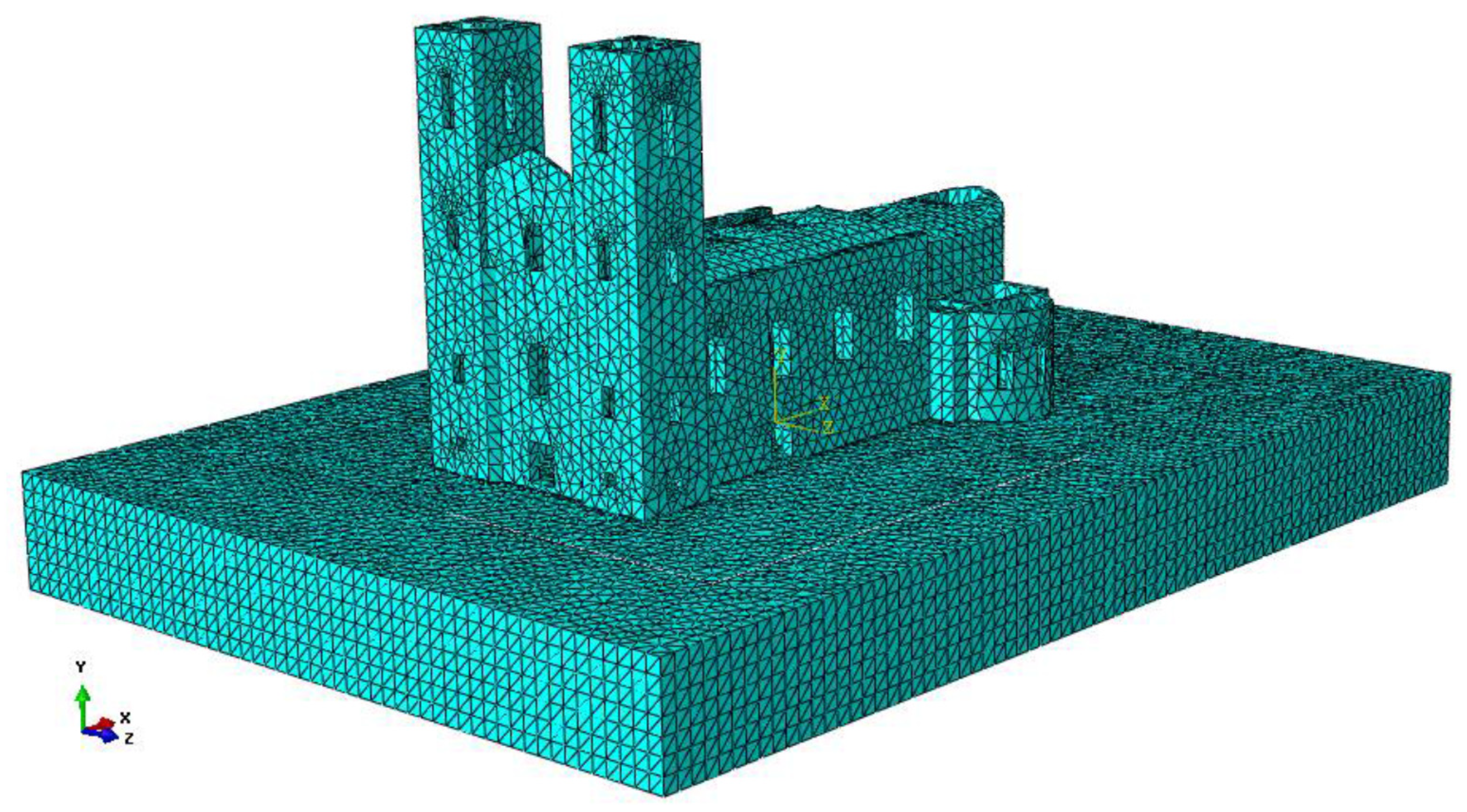
Figure 11 depicts the general shape of the model, while
Figure 12 depicts the FE mesh of the Cathedral and the surrounding soil that was taken into account for the calculations. The FE analysis was performed with software Ansys
® Academic Teaching Mechanical, Release 17.
The masonry was simulated with the SOLID65, 3D element type from the Ansys Element Library, while for the soil, the SOLID185 element was used. Special attention was devoted to finding an adequate FE mesh, in order to optimize the accuracy of the results, convergence and hardware limitations. As a result, the masonry was modelled with 45,115 elements, and the soil with 192,070 elements, 237,185 elements in total. Timber elements of the Cathedral roof structure were introduced as loads applied on the locations that represent support points for the real structure. Compared to the rest of the structure, these structures have relatively small effects. The bell section of each tower has a weight of 37.5 tons compared to the total weight of each tower, which is 3200 tons. The weight of the roof over the nave is 225 tons, compared to the total weight of the nave of approximately 7000 tons. Since the numerical model is relatively large, material nonlinearities were utilized only for the soil. The masonry was modelled with the linear material model, without cracking. The effect of the existing cracks was introduced in the form of voids that extend throughout the walls. This simplification was adopted after the series of simulations with material nonlinear models both for the masonry and for the soil proved to be too demanding for hardware that was available at the time. On the other hand, the results obtained from the simplified model have a good agreement with the damages observed on the structure itself. The soil was modelled with the Mohr–Coulomb material model. The numerical values used for the definition of this material model were obtained from numerous in situ soil testing, laboratory testing of the soil samples from the site and for the modulus of elasticity, as shown in
Section 3.1 of this paper. The boundary conditions on the outer surfaces of the soil,
Figure 12, were defined to have no displacements.
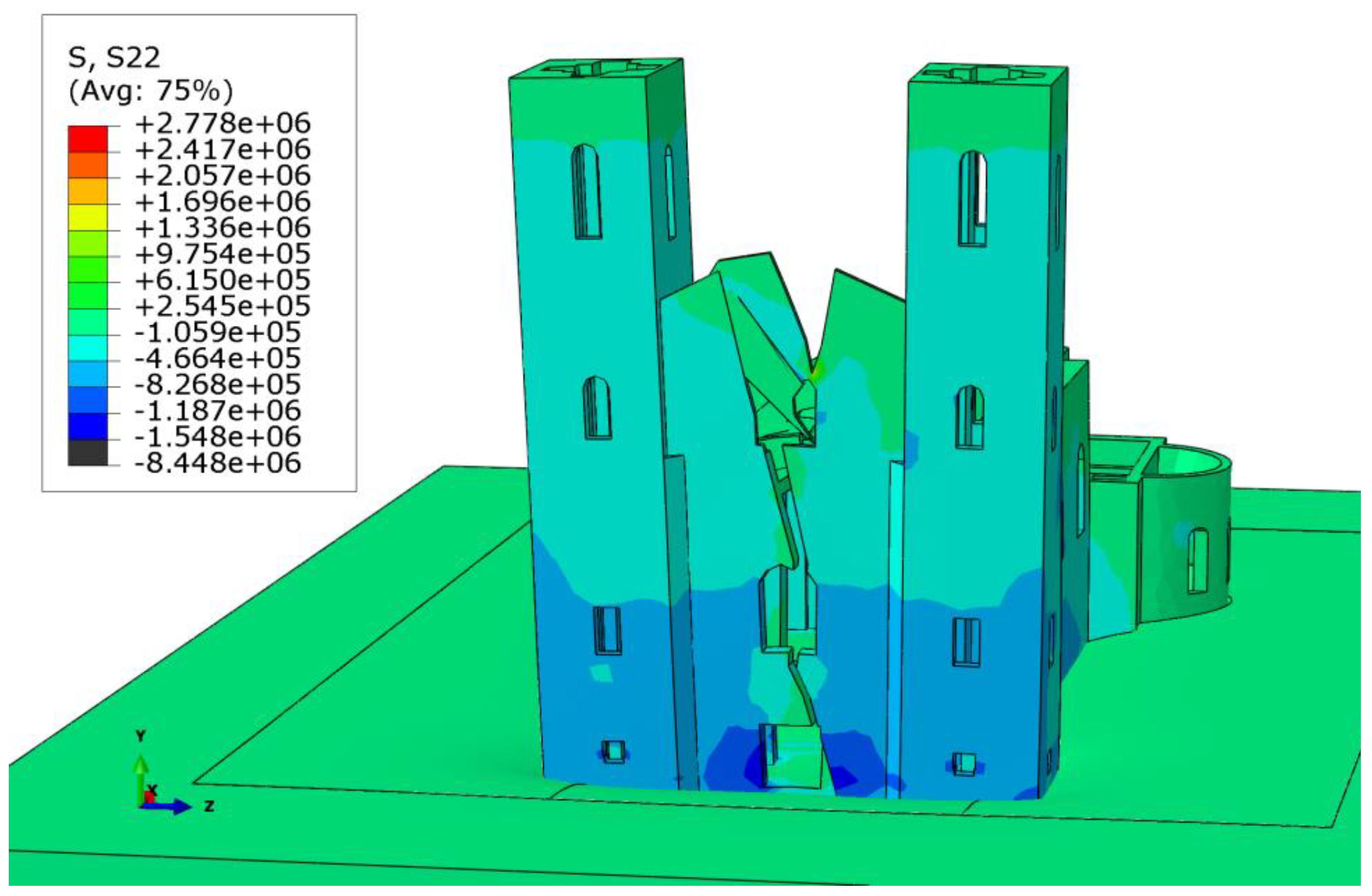
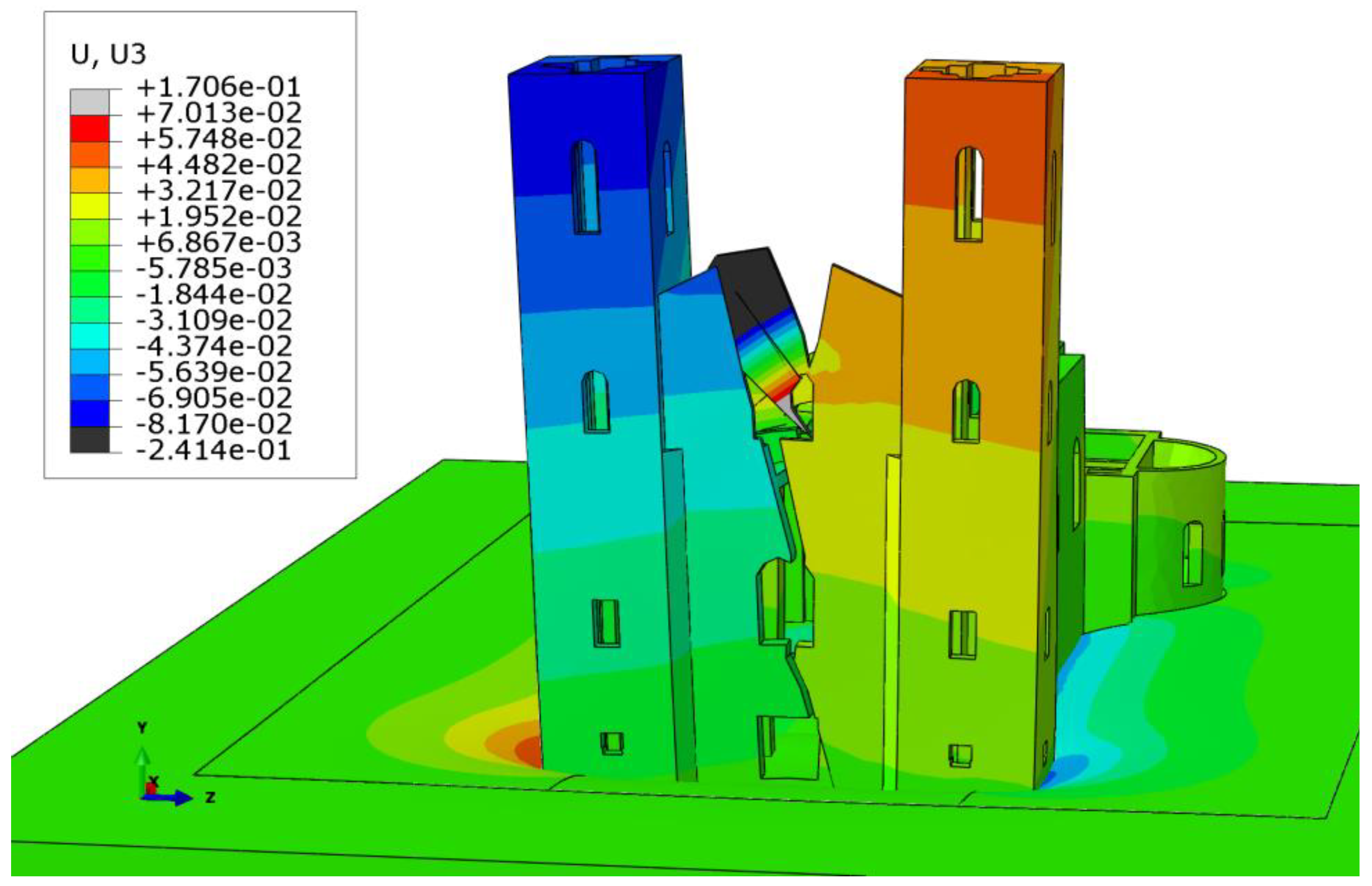
Overall calculations related to this structure consisted of both static and dynamic analysis, but for the purpose of this paper, the results showed here are related to the effects of self-weight, which govern the damaging long-term settlements that led to such extreme cracks observed on the Cathedral.
Figure 13,
Figure 14,
Figure 15,
Figure 16 and
Figure 17 therefore all show the effects of the permanent gravity loads on the structure.
Calculations have shown (
Figure 13 and
Figure 14) that the maximum edge pressure is below the southeast and northeast corners of the tower, and is about 816 kPa, which is much greater than the centric stress. The divergence of the towers is about 6.0 mm/m. Although the 3D model is a rough approximation of the actual condition in the structure and soil, the results of static calculation agree well with the results of visual observation of what happens to the object and measurement results, which is a good starting point for determining the methodology of structural rehabilitation.
4. Considered Variants of Foundation Rehabilitation
Based on the analysis of the measurement results and performed calculations, it is concluded that the primary cause of the problem with the Cathedral towers is the unusually high pressure on the layer of compressible clay, which caused large consolidation settlement. Another reason is the eccentric load on the foundation, which caused the towers to tilt. These two quantities are cause-and-effect, because eccentricity causes inclination and inclination increases eccentricity, etc. In addition, the critical height of the centre of gravity makes the structure sensitive and unstable to the effects of relatively small horizontal forces. Starting from the assumption that the cause of the problem is high pressure on the ground and eccentricity of the load, it is logical that the solution is to reduce the weight and pressure on the ground, strengthen the soil and tighten the towers. One “obvious” strategy for tightening the towers is to apply steel ties, anchored in the large hidden anchor blocks that would not disturb or change the appearance of the front facade. However, the lessons from previous, historic experiences with ties within this structure, and the fact that this structure is a high masonry building, not resistant to bending, raises reasonable suspicion that further settlement due to creep would compromise this solution with excessive stretching of ties and horizontal cracks in the tower walls. Additionally, this solution cannot solve the problem of the towers tilting eastwards, away from the nave. Hawing this in mind, it is much more appropriate to tighten the towers with a strong, massive, reinforced concrete (RC) frame that would be hidden beneath the facade,
Figure 18.
The additional (hidden) RC frame was supposed to be joined with the existing masonry by installing a series of anchors. The size of the RC frame, and the dimensions of interaction surfaces, combined with the anchors, was expected to ensure the joint work of the old and the new structure. With additional structural elements, this RC frame can be joined with the nave, therefore utilizing its mass to counteract the eastward tilting of the towers. On the downside, this strategy raises the issue of increased additional weight and increased pressure on the ground. Hawing in mind all the above, it was concluded that this type of tightening must be combined with partial soil reinforcement, to exclude further soil deformations.
Two possibilities of increasing the bearing capacity of the soil were considered, one of which was “jet-grouting” technology, and the other was the injection of steel piles under the foundation. Both methods belong to invasive construction technologies, since they require temporary and local weakening of foundations and soil through digging, drilling, and grouting. Given the tendency of lime concrete to soften due to fluid drilling, and the significantly higher price, instead of jet-grouting, the preference was given to the installation of jacked-in piles (“mega-piles”).
Following the detail analysis of all the above-mentioned aspects of this problem, an additional proposal was formed that would lead to reduced pressure on the ground, while increasing the overall structural strength. This would have to include a partial dismantling of the upper sections of the towers, which would then be reconstructed with all the necessary strengthening elements and reduced weight—see
Figure 19. The initial calculations showed that the pressure reduction would be approximatively 15 to 20%. This solution is also supported by the fact that several large structural elements of the front facade were planned for total reconstruction even before the increased settlements raised the question of the structural stability of the towers, such as: the dilapidated roof structure of the tower and the middle section of the facade wall that currently has extremely large cracks and damages. Additionally, new bell carriers, platforms and internal tower stairways need to be built. The major advantage of this strategy is that it allows for the possibility of unhindered construction of the powerful reinforced concrete frame that would connect the towers themselves, and the towers with the nave of the Cathedral. From a structural point of view, this solution is clean, simple, and durable, it does not require soil reinforcement or the installation of steel ties and anchor blocks, and lastly, it is affordable.
However, since the Cathedral represents a significant cultural heritage monument, this solution was initially put on hold, until other strengthening strategies, however few, are explored.
4.1. Construction of the Jacked-in Piles (Mega-piles) Beneath the Foundation and Its Consequences
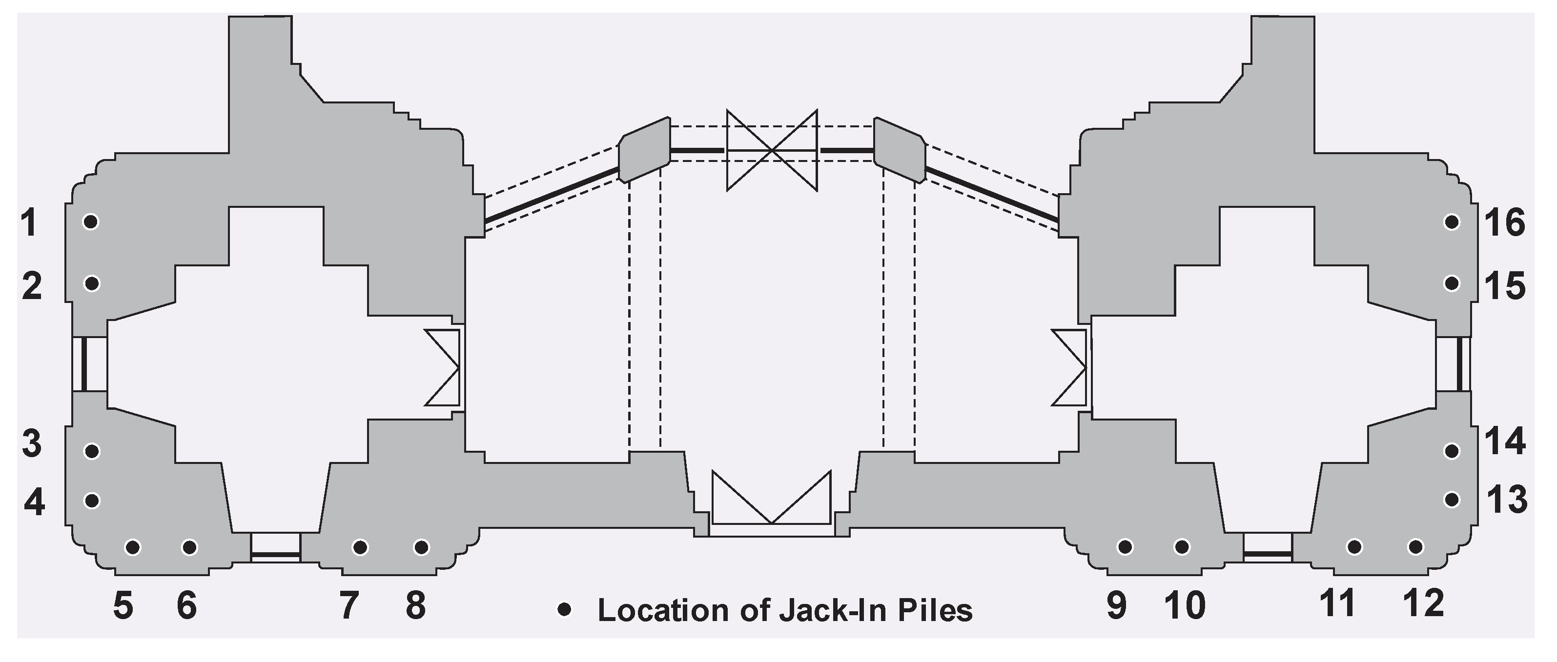
The underlaying idea of strengthening the soil with jacked-in piles was based on improving the bearing capacity of the soil beneath the two outer edges of the tower foundations. The calculation showed that in this way, with a relatively small force in the piles, the angular pressure on the ground could be reduced and thus stop the further tilting of the towers. There were four piles planned along the outer edges of the tower foundation, i.e., a total of eight piles under each tower (
Figure 20).
Each pile consists of several steel segments–cylinders with a diameter of 323 mm and a height of 500 mm. In order to install the piles, a narrow trench was excavated next to the foundation. From this trench, the working space (“a gallery”) within the foundation was excavated, 1.3 m high, 1.0 m wide and 0.8 m deep. The galleries were excavated in succession—the work on the new pile did not start before the previous one was activated. Relative to the total foundation area of 128 m
3, one such gallery represented less than 1%. Inside the gallery, a steel frame and a hydraulic jack were placed. The hydraulic jack was used to press steel cylinders, one by one, into the ground beneath. The initial steel cylinder of each pile was formed with a conical tip. All segments were welded to each other continuously along the circumference. The piles were pressed all the way down to the layer of sand, where the pressing force was limited to 0.74 MN, so as not to cause a shear fracture in the lime concrete foundation footing above the pile. The resistance diagram of piles being pressed into the ground is shown in
Figure 21, and it is very similar to the tip resistance (CPT) in
Figure 5.
During the works on the pile installation, monitoring of the geodetic markers movement was continuous in order to prevent negative effects that can accompany this foundation strengthening method. Initial, “zero”, recording was performed on 6 March 2017 and the first pile was installed on 9 March 2017. After the installation of the last pile segment, the gap between the steel frame and the pile is wedged, the hydraulic jack is removed and the working gallery is concreted. It is of the utmost importance that the wedge is locked adequately, so that the drop in pile force after removing the hydraulic jack is minimized. Due to the geodetic measurements, after installation of a few piles, a settlement of 1 to 2 mm order of magnitude was observed. As the work progressed, this became increasingly intense with each new pile. The settlement was accompanied by the appearance of new cracks and expansion of the existing ones. Consequently, on 2 April 2017, after the installation of 11 piles, the works were stopped, without piles number 2, 5, 6, 11 and 14 being installed. Geodetic measurements showed that the settlements on both towers reached values between 6 and 8 mm. The inclination of the south tower was increased by 0.4 mm/m and the north by 0.6 mm/m, while the inclination of both towers from the nave were increased by 0.4 mm/m. The total crack width was increased by approximately 4 cm, from 15 to 19 cm. After the cessation of the works, the measurement of the settlement continued on a monthly basis. It was determined that the settlement rate gradually calmed down within the next nine months and, by the end of the year, it fell below geodetic accuracy. In the meantime, possible causes of unsuccessful remediation were analysed, and it was concluded that it was most likely due to a multiple cause, such as sensitivity to weakening of the foundation, vibration of the pneumatic hammer during gallery excavation and slight loosening of the wedges.
4.2. Injection of Polyurethane Resins into the Foundation Soil and Its Consequences
The negative experience with the jacked-in piles ruled out solutions that would include interventions/strengthening on the foundations themselves and reaffirmed the idea of reducing the weight of the towers, as well as the idea of adding massive side apses with pile foundations to stabilize the towers.
Figure 1a depicts the present appearance of the front facade, and
Figure 22 depicts the remediation proposal with additional massive apses.
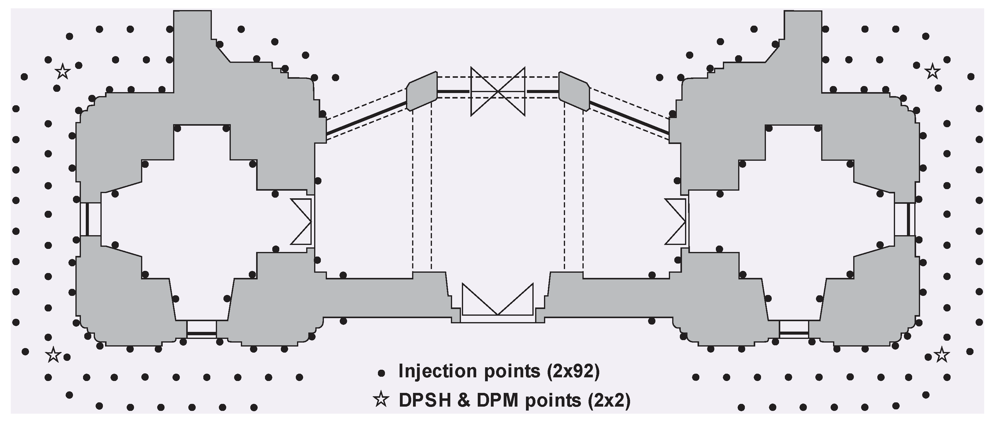
However, such solutions were not in accordance with the existing restoration guidelines for cultural monuments protection and therefore were not accepted. At the investors request, an expert team from Budapest proposed, in October 2017, the stabilization of the towers by means of deep grouting of soil with polyurethane expanding resin. During penetration and expansion, the resin exerts pressure on surrounding soil, and creates and penetrates cracks in the form of a branched root. This method was originally developed by the oil industry to increase the yield of wells, while in geotechnics it has been adapted for the purpose of precise remediation of settlement under structures. Based on their experiences on similar objects that were also damaged by excessive settlement, the expert team guaranteed the cessation of the settlement with local uplift of the structure and/or surrounding terrain in the order of magnitude up to 0.5 mm. The injection was performed through long steel pipes with a 12 mm diameter. During the injection procedure, upward movement of the geodetic wall markers is considered to be a proof of successful soil stabilization. The project envisaged the stabilization of the ground beneath the northern and then beneath the southern tower, at 2 × 92 injection points at a depth of 2, 3, 4, 5, 6, 7, 8, 9 and 10 m, measured from the ground surface. The external injection points were placed in three rows, the first row along the wall, the second and third row at a distance of 1 m and 2 m from the wall, respectively. The internal injection points were placed only in one row along the inner walls—see
Figure 23. First, the outer row was injected at a distance of 2 m, then the row at a distance of 1 m, and finally, the rows directly next to the tower wall on the outside and on the inside. The downward direction of injection along the wall is sloping at an 8° angle towards the wall, while the other directions are vertical. The works lasted from February to August 2018. According to an approximate calculation, the volume of injection mass per injection point, after expansion, is about 0.17 m
3, or a total of 15.5 m
3 for each tower. If the average injection radius is about 0.3 m, then in relation to the affected soil volume around the injection pipe, the initial soil porosity of about 0.45 should have been reduced by about 15%.
To determine the effect of injection, a continuous test of the soil with dynamic penetrometers was performed, at four locations before and after injection,
Figure 24.
Based on comparative diagrams, at depths below 3 m, a certain increase in soil resistance is observed beneath both towers as a result of injection. Increasing the penetration resistance means that in a certain region of the soil around the foundation, the strength and stiffness of the soil are increased, which should have favourable consequences on the foundation bearing capacity. However, contrary to expectations, very soon after the beginning of the soil injection, next to north tower, an increase in settlement and the appearance of new cracks in the walls and arches of the Cathedral nave was observed. These effects were significantly less favourable than the ones observed during jacked-in piling. Based on the assumption that the settlement was the result of a large increase in pore pressure and a decrease in effective stresses in the clay, the contractor reduced the injection speed, which prolonged the works. Despite this, the settlement continued at a lower intensity. In order to gain an insight into settlement dynamics, geodetic measurements were performed during and after the injection for 12 h straight, with final measurement conducted 24 h after the injection. The geodetic markers were measured on the south tower, above the injection point next to the wall. Settlement from 10 July 2018, at 08:42, until the next day, 11 July 2018, at 07:49 are shown in
Figure 25.
The geodetic markers were measured eight times during working hours, and the ninth measurement was on the next day, shortly before the next injection session continued. According to the diagram, the markers showed upward movement that had a peak during the injection of 0.21 to 0.25 mm, but after injection ceased, the markers began to move downward. After 24 h, out of 0.25 mm rise, only 0.01 mm remained on the marker A-21. The marker A-20 showed a downward movement of 0.03 mm, after reaching 0.21 mm of upward movement. Based on the shape of the displacement curve, it can be concluded that, despite the initial rise during injection, both markers eventually have some settlement. Although the individual settlements are very small, when superimposed for each injection point (2 × 92 points), settlements of 8 to 10 mm were observed. In other words, during and after polyurethane resins injection, soil with reduced permeability, instead of increasing the soil volume around the injection zone, showed a permanent reduction [
15].
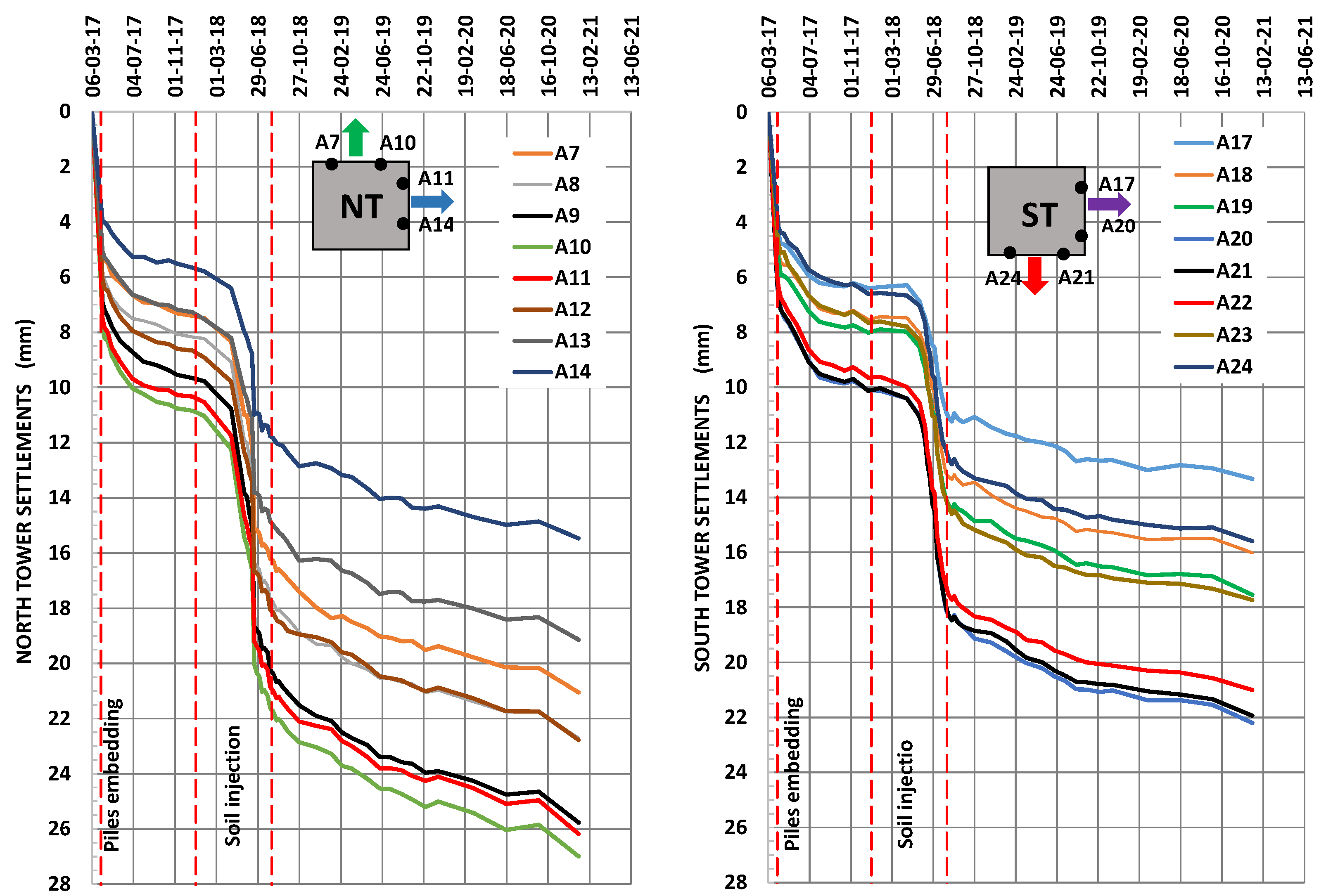
The results of geodetic marker settlement measurements, during and after the completion of rehabilitation works, are shown in
Figure 18. Geodetic measurements covered a period of about 2.5 years, after the completion of the rehabilitation works, and as it can be seen, the total settlement of the north tower geodetic markers is between 5 and 27 mm, and the south between 13 and 22 mm. Uneven settlement indicates the inclination of the towers, the direction of which is indicated by the arrows in
Figure 26.
During the installation of the jacked-in piles, the geodetic markers on both towers showed approximately the same level of settlement, 6 to 11 mm. After the soil injection with polyurethane expanding resin was completed, these settlements increased to 11 to 22 mm for the northern, and to 11 to 19 mm for the southern tower. Approximatively 2.5 years after injection, settlements increased by an average of an additional 4 mm for the north tower and 3 mm for the south tower, meaning that neither piles nor grouting stopped the settlements.
Figure 27 shows the average settlement and the average settlement increment of the geodetic markers. It is evident that, as with the settlements (
Figure 26), the average settlements of the northern tower, which was founded at a depth of 2.5 m, are about 4 mm larger than the ones of the southern tower, which is founded at a depth of 3.0 m from the surface around the Cathedral.
After the completion of the injection of piles, which was followed by very intensive settlement, the average settlement rate slowed down and practically stabilized at about 0.07 mm/month in both towers. However, when the injection of soil under the north tower began, the settlement of the north tower accelerated, while on the south tower the rate of settlement remained the same. It was only when the injections under the south tower began that its settlement also accelerated. The injection process was accompanied by intense settlement, which began to slow down only after completion of the works. After about a year, the settlement of both towers has stabilized, with the northern tower at about 0.08 mm/month and the southern tower at about 0.05 mm/month. While after the installation of the piles, the settlement rate of both towers remained the same, after the injection, the rate of the north tower was about 50% higher than the settlement rate of the south tower. The last measurement, which was performed in January 2021, showed an increase in the settlement rate, which is more clearly seen in
Figure 19, where the settlement increments are shown in two consecutive measurements. The reason for that is the earthquake in Croatia in December 2020, which was also felt in Subotica, in the period between two geodetic measurements. The diagram showing the increments of the average settlement clearly shows that there was a tendency to decrease, which was disturbed by the seismic actions.
In order to explain the measured monthly settlement of towers of 0.05 to 0.08 mm/month (
Figure 27), it should be noted that the settlement on clay consists of three components: instantaneous settlement, settlement due to primary consolidation and settlement due to secondary compression (creep). Having in mind the construction time, the first two components were completed, so only the settlement due to creep remained. Based on the time required to complete settlement due to primary consolidation of about
t100 = 6.0 years and the secondary compression index
Cα which can be estimated by compressibility index
Cc = 0.18, from the oedometric test (Mesri and Godlewski, 1977), the settlement due to creep from 1912 to 2017, or for about 105 years, is:
If the settlement due to creep for
t = 105 years is about 64 mm, then the average monthly settlement due to creep is about:
The calculated size of 0.051 mm/month approximately corresponds to the order of magnitude of the measured monthly settlement of the towers, which is shown in
Figure 19.
4.3. Discussion and Possible Future Research Directions
For the reconstruction and strengthening of the Cathedral structure to be successful, it was extremely important to determine, beyond any doubt, the governing cause of its current damages. By unifying all the findings from the available historic data, and reconstruction efforts since 2015, it was concluded that the damages were caused by extremely high contact stresses in the soil which still cause steady and relatively uniform settlements. This fact directed the remediation proposals towards very invasive measures, but ones that are deemed unavoidable—partial dismantling of the towers followed by their reconstruction. The reconstruction is to be completed in such a way that the outer appearance remains the same but with the lighter and stronger structure. This type of reconstruction measure would reduce the soil pressures, and consequently future settlements, so that they cause no more damage to the structure.
Prior to the final decision regarding the acceptance of the proposed solution, all other aspects of the reconstruction must be explored. In recent years, there were several structures, similar to this one, that have undergone major repair and strengthening works and that could be used as examples of good practice. One of these is the strengthening of the ancient masonry tower in Torre Orsaia (Italy), [
16]. The authors of this reconstruction managed to achieve sufficient strengthening without applying very invasive techniques. A similar example is the restoration of the “Carmine Maggiore” bell tower in Naples (Italy), [
17]. Apart from the damages caused by the passage of time, most of the damages on this tower were caused by earthquakes, while no damages were observed or attributed to the foundation structure. Both examples are characterized by minimization of the structural interventions, which should always be the goal when dealing with historic buildings. On the other hand, in both cases, there were no severe damages caused by increased and uneven settlements, so this gave more freedom for the strengthening techniques to be chosen.
Future research and investigations that could help with making a final decision related to the strengthening technique should utilize some of the recent analysis tools that were proposed. Since the Cathedral, in its current state, is very sensitive, even to the smallest uneven settlements, the ground water level can induce some negative effects on the dynamic properties of the towers, and therefore reduce its current capacity to resist seismic forces. Provided that current measurement methods are improved with the addition of accelerometers and other long-term monitoring devices, some simplified, low-cost methods to evaluate the dynamic soil–structure interaction for varying ground levels are available [
18] that are also non-destructive and based on neural networks.
The numerical analysis shown in this paper was focused on the general understanding of the mechanisms that lead to the current state of the structure and it utilized nonlinear material models only for the soil, while the masonry was modelled with linear materials. Some recent studies, such as the evaluation of the seismic vulnerability of the Trani Cathedral’s bell tower (Italy) [
19], showed good results by combining sophisticated numerical modelling and experimentally obtained measurements. A seismic risk study shown for the Norman tower of Craco in Matera (Italy) [
20] proposes the simplified and versatile procedure for the seismic risk evaluation of historic buildings.
Even though the excessive damage, observed on the masonry, is caused by the weak foundations and not by the masonry itself, it was found that the quality of the masonry and the mortar is very inconsistent throughout the Cathedral. These material properties, combined with construction imperfections, make the estimation of the load-bearing capacity for these masonry elements very difficult. The application of artificial neural networks can be applied for this task as well [
21]. Most of the parameters for this approach to be applied can be found in previous analyses and material tests. This approach would require additional tests for masonry stiffness and tensile strength of the masonry, but these tests would be generally beneficial, so they should be conducted.
5. Conclusions
Considering the historic data related to the Cathedral, registered damages, results of geodetic measurements and experiences gained from rehabilitation works, it can be concluded that this is a very complex problem of interaction between a very heavy object on one side and a poorly load-bearing base on the other. From the professional point of view, it is safe to say that, in this case, an inadequate foundation system was applied, and that instead of shallow foundation, it was obviously necessary to apply deep foundation on piles. It is not clear why the builders of that time opted for shallow foundations of relatively heavy and high Cathedral towers, which caused very high contact stresses on the soft water-saturated clay base, when adequate knowledge, experience and means for installing piles existed at that time.
The paper shows that in terms of calculated settlements and low soil compressibility, the centre of gravity of the towers is close to the critical height, making them very sensitive to relatively small side effects. The result of such relations, in the long run, causes uneven settlements and progressive tilting of the towers. This is clearly shown by the continuously increasing width of cracks on the front facade wall, which, in the present form, appeared after the restoration of the facade in 1912, and continued to grow until the rehabilitation work attempts during 2017 and 2018, and to this day.
The results of geodetic measurements and geotechnical calculations also showed that the foundations of the towers are exposed to the process of very small but constant settlements due to soil creep. Such settlements, over a long period of time and eccentric loading, cause progressive tilting of the towers and the propagation of cracks. This process, due to its nature, cannot be stopped by itself, but will only accelerate and worsen the general condition of the building over time.
The inclination of the towers, weak construction of the foundation footings, very high contact stresses in the soil, and a relatively low soil permeability indisputably contributed to the rehabilitation failures, which themselves were also significantly invasive in character. Intensive, continuous measurements during one of the PU resin soil injection sessions showed that the towers initially moved upwards, but this was followed by a slower downward movement, therefore rendering this approach not only ineffective but also damaging.
All of this leads to the conclusion that the solution for rehabilitation should not be sought in the soil, but in reducing the weight of the towers, i.e., reducing the pressure on the ground. Of course, due to the nature of creep, reducing the weight of an object cannot completely stop settlement, but it can significantly slow it down.
Partial dismantling of the towers, their interconnection and connection to the nave of the Cathedral by means of a powerful reinforced concrete frame, followed by their rebuilding with lighter materials, preserving the current appearance, can solve the problem of cracks in the long run with a radical extension of the service life.
Author Contributions
Conceptualization, P.S., D.K., and S.G.; writing–original draft preparation, P.S.; writing–review and editing D.K. and S.G.; software, M.S.; validation, P.S., D.K., S.G., and N.Đ.; data curation, N.Đ.; visualization, M.S.; formal analysis, P.S. and N.Đ.; project administration, P.S., D.K., S.G.; funding acquisition, P.S., D.K., and S.G. All authors have read and agreed to the published version of the manuscript.
Funding
This research received no external funding.
Institutional Review Board Statement
Not applicable.
Informed Consent Statement
Not applicable.
Acknowledgments
The realization of the research presented in this paper, most prominently, experimental research, was supported by companies “Geoexpert Ltd.”, “Construction Center Ltd.” and “Invest Pro Centar Ltd.” from Subotica.
Conflicts of Interest
The authors declare no conflict of interest.
References
- Csak, B. A Study on the Assessment of the Condition of the Cathedral of St. Theresa of Avila in Subotica (Tanulmány a szabadkai Avilai szent Teréz székesegyház állapotának értékeléséről); Department of Mechanics, Materials and Structures, Budapest University of Technology and Economics: Budapest, Hungary, 2009. (In Hungarian) [Google Scholar]
- Preliminary Repair Design of the Roman Catholic Church of St. Theresa of Avila in Subotica; Šidprojekt JSC: Šid, Serbia, 2015. (In Serbian)
- Technical Report on the Testing of the Mortar and Bricks from the Outer Walls of the Church of the St. Theresa of Avila in Subotica; Institute IMS, JSC: Belgrade, Serbia, 2015. (In Serbian)
- Technical Report, No. 02/15-20, on the Monitoring of the Horizontal and Vertical Displacements; Geopanonija Ltd.: Novi Sad, Serbia, 2015. (In Serbian)
- Technical Report, No. EG-041/15, on the Geomechanical Conditions for the Construction; Geoexpert Ltd.: Subotica, Serbia, 2015. (In Serbian)
- Structural Design: Strengthening of the Foundation and the Foundation Soil, Stiffening the Towers and the Frontage Wall Cathedral St. Theresa of Avila in Subotica; Geoexpert Ltd.: Subotica, Serbia, 2016. (In Serbian)
- Technical Report on the Testing of the Soil Permeability before and after the Soil Injection (Talajtömörség vizsgálata Injektálás előtt es injektálás után); Csillagtér Építőipari Ltd.: Budapest, Hungary, 2018. (In Hungarian)
- Technical Report on the Stabilization of the Soil beneath the Towers of the Cathedral of St. Theresa of Avila in Subotica (Jelentés a talaj stabilizálódásáról a szabadkai Avilai Szent Terézia székesegyház tornyai alatt); ABA Inovator Ltd.: Subotica, Serbia, 2019. (In Hungarian)
- Technical Report on the Measurement of the Verticality of the Towers of the Cathedral of St. Theresa of Avila in Subotica; Geosoft Ltd.: Belgrade, Serbia, 2017. (In Serbian)
- Monthly Technical Reports on the Settlements of the Geodetic Markers on the Cathedral of St. Theresa of Avila in Subotica; Subotica, Serbia. From 2017 to 2021. Available online: http://www.szt.bme.hu/18-tartoszerkezet-tervezk/a-magyar-statikus-tarsadalom-nagyjai?start=8 (accessed on 27 May 2021). (In Serbian).
- Mayne, P.W. In-Situ Test Calibrations for Evaluating Soil Parameters. Characterization and Engineering Properties of Natural Soils. In Proceedings of the Second International Workshop on Characterization and Engineering Properties of Natural Soils, Singapore, 29 November–1 December 2006; Volume 3, pp. 1–56. [Google Scholar]
- Timoshenko, S.P.; Goodier, J.N. Theory of Elasticity, 3rd ed.; McGraw-Hill: New York, NY, USA, 1982; pp. 398–409. [Google Scholar]
- Taylor, D.W. Fundamentals of Soil Mechanics; John Wiley: New York, NY, USA, 1948. [Google Scholar]
- Nonveiller, E. Soil Mechanics and Foundation Structures; Školska Knjiga: Zagreb, Croatia, 1980. (In Croatian) [Google Scholar]
- Segars, S. Uretek Deep Injection Method—Full Scale Test. Master’s Thesis, Faculty of Civil Engineering and Geosciences, TU Delft,, Delft, The Netherlands, 2006. [Google Scholar]
- Ferraioli, M.; Lavino, A.A. Seismic Assessment, Repair and Strengthening of a Medieval Masonry Tower in Southern Italy. Int. J. Civ. Eng. 2020, 18, 967–994. [Google Scholar] [CrossRef]
- Nuzzo, M.; Faella, G. The carmine maggiore bell tower: An inclusive and sustainable restoration experience. Sustainability 2021, 1445, 1–30. [Google Scholar]
- Ivorra, S.; Brotóns, V.; Foti, D.; Diaferio, M. A preliminary approach of dynamic identification of slender buildings by neuronal networks. Int. J. Non-Linear Mech. 2016, 80, 183–189. [Google Scholar] [CrossRef] [Green Version]
- Diaferio, M.; Foti, D. Seismic risk assessment of Trani’s Cathedral bell tower in Apulia, Italy. Int. J. Adv. Struct. Eng. 2017, 9, 259–267. [Google Scholar] [CrossRef] [Green Version]
- Diaferio, M.; Foti, D.; Sabbà, M.F.; Lerna, M. A procedure for the seismic risk assessment of the cultural heritage. Bull. Earthq. Eng. 2021, 19, 1027–1050. [Google Scholar] [CrossRef]
- Garzón-Roca, J.; Adam, J.M.; Sandoval, C.; Roca, P. Estimation of the axial behaviour of masonry walls based on Artificial Neural Networks. Comput. Struct. 2013, 125, 145–152. [Google Scholar] [CrossRef]
Figure 1.
View of the north-eastern part of the Cathedral prior to 2017. (a) Cathedral, north-eastern view prior to 2017, (b) Interior view towards the altar, (c) Interior view towards the entrance.
Figure 1.
View of the north-eastern part of the Cathedral prior to 2017. (a) Cathedral, north-eastern view prior to 2017, (b) Interior view towards the altar, (c) Interior view towards the entrance.
Figure 2.
(Left) Cracks in the front facade wall; (Right) Crack details on the upper window.
Figure 2.
(Left) Cracks in the front facade wall; (Right) Crack details on the upper window.
Figure 3.
Cracks in the longitudinal wall—north facade.
Figure 3.
Cracks in the longitudinal wall—north facade.
Figure 4.
Crack monitoring gauges within the Cathedral—inner side of the front facade wall.
Figure 4.
Crack monitoring gauges within the Cathedral—inner side of the front facade wall.
Figure 5.
All penetration tests next to the towers (
left) and average of all tests (
right) [
5].
Figure 5.
All penetration tests next to the towers (
left) and average of all tests (
right) [
5].
Figure 6.
Results of groundwater level monitoring around the Cathedral [
5].
Figure 6.
Results of groundwater level monitoring around the Cathedral [
5].
Figure 7.
Appearance of the cleaned side surface of the lime concrete foundation.
Figure 7.
Appearance of the cleaned side surface of the lime concrete foundation.
Figure 8.
Characteristic damages: facade wall, tower wall cladding, cracks in the nave vaults.
Figure 8.
Characteristic damages: facade wall, tower wall cladding, cracks in the nave vaults.
Figure 9.
Linear interpolation of observed points on tower lining [
9].
Figure 9.
Linear interpolation of observed points on tower lining [
9].
Figure 10.
Correlation of soil compressibility modulus and cone resistance [
11].
Figure 10.
Correlation of soil compressibility modulus and cone resistance [
11].
Figure 11.
3D model of the Cathedral—general shape of the model.
Figure 11.
3D model of the Cathedral—general shape of the model.
Figure 12.
FE mesh of the Cathedral numerical model with the surrounding soil.
Figure 12.
FE mesh of the Cathedral numerical model with the surrounding soil.
Figure 13.
Vertical contact stresses in the soil at the idealized (flat) bottom surface (N/m2).
Figure 13.
Vertical contact stresses in the soil at the idealized (flat) bottom surface (N/m2).
Figure 14.
Characteristic points for contact stresses below the foundations of the Cathedral.
Figure 14.
Characteristic points for contact stresses below the foundations of the Cathedral.
Figure 15.
Vertical stresses in the masonry (N/m2).
Figure 15.
Vertical stresses in the masonry (N/m2).
Figure 16.
Horizontal displacement of the structure “north-south” direction (m).
Figure 16.
Horizontal displacement of the structure “north-south” direction (m).
Figure 17.
Modal analysis—first modes in two orthogonal directions.
Figure 17.
Modal analysis—first modes in two orthogonal directions.
Figure 18.
Proposed RC frame.
Figure 18.
Proposed RC frame.
Figure 19.
Upper sections of the towers and front façade—proposed total reconstructions.
Figure 19.
Upper sections of the towers and front façade—proposed total reconstructions.
Figure 20.
Layout of the piles below the foundations of the towers.
Figure 20.
Layout of the piles below the foundations of the towers.
Figure 21.
Measured resistances on the hydraulic jacks when pressing piles.
Figure 21.
Measured resistances on the hydraulic jacks when pressing piles.
Figure 22.
Remediation proposal with additional massive apses.
Figure 22.
Remediation proposal with additional massive apses.
Figure 23.
Position of injection points around the foundations of the towers.
Figure 23.
Position of injection points around the foundations of the towers.
Figure 24.
Results of penetration tests before and after soil injection.
Figure 24.
Results of penetration tests before and after soil injection.
Figure 25.
Movements of geodetic markers A-20 and A-21 during and after injection.
Figure 25.
Movements of geodetic markers A-20 and A-21 during and after injection.
Figure 26.
Diagrams of geodetic markers settlement during and after remediation works.
Figure 26.
Diagrams of geodetic markers settlement during and after remediation works.
Figure 27.
Diagrams of average settlement and average increment of settlement.
Figure 27.
Diagrams of average settlement and average increment of settlement.
Table 1.
Measured eccentricities of the towers ex and ey.
Table 1.
Measured eccentricities of the towers ex and ey.
| South Tower of the Cathedral | North Tower of the Cathedral |
|---|
θx
(mm/m) | θy
(mm/m) | ex
(mm) | ey
(mm) | θx
(mm/m) | θy
(mm/m) | ex
(mm) | ey
(mm) |
| −3.79 | −2.16 | −57 | −32 | 1.33 | −2.88 | 20 | −43 |
Table 2.
Calculated inclination of the towers θx and θy.
Table 2.
Calculated inclination of the towers θx and θy.
| South Tower of the Cathedral | North Tower of the Cathedral |
|---|
θx
(mm/m) | θy
(mm/m) | ex
(mm) | ey
(mm) | θx
(mm/m) | θy
(mm/m) | ex
(mm) | ey
(mm) |
| −4.22 | −2.41 | −57 | −32 | 1.48 | −3.21 | 20 | −43 |
| Publisher’s Note: MDPI stays neutral with regard to jurisdictional claims in published maps and institutional affiliations. |
© 2021 by the authors. Licensee MDPI, Basel, Switzerland. This article is an open access article distributed under the terms and conditions of the Creative Commons Attribution (CC BY) license (https://creativecommons.org/licenses/by/4.0/).


