Article

Vibration and Derailment Analyses of Trains Moving on Curved and Cant Rails

Department of Civil Engineering, National Cheng-Kung University, Tainan City 70101, Taiwan
*
Author to whom correspondence should be addressed.
Appl. Sci. 2021, 11(11), 5106; https://doi.org/10.3390/app11115106
Submission received: 5 May 2021 / Revised: 22 May 2021 / Accepted: 27 May 2021 / Published: 31 May 2021
(This article belongs to the Section Acoustics and Vibrations)

Abstract

:
A moving axle finite element (FE) was developed to study the contact between a wheel and curved rail, where the FE can simulate multi-point contact with sticking, sliding, and separation modes. The possible contact region is inputted as a number of nodes along the wheel and rail surfaces, while the wheel nodes are simulated as cubic-splines. The rail node to wheel cubic-splines contact method is then used to find the normal and shear forces, where the normal and tangential stiffness values obtained from the three-dimensional (3D) FE analysis for an actual wheel and rail are used to model the force–displacement relationship. A simple theoretical solution for curved railways was used to validate the proposed FE in 3D analyses. The results show that good agreement with the theoretical and FE solutions for the contact normal force, shear force, wheel sliding, and wheel separation under various train speeds, curve radius, cant angles, and friction coefficients. This FE can be used in combination with other elements to simulate a train traveling on a curved track system, in which only the standard Newton–Raphson and Newmark’s methods are required in the FE main program.

1. Introduction

High-speed rail and mass rapid transit have become important transportation modes on a global scale, so safety and passenger comfort need to be taken seriously, especially in the case of curved railway systems. The vibration and derailment behavior of trains moving on curved rails are much more complicated than those on straight line rails. Thus, investigation of moving trains on curved rails is an important issue. There have been a number of studies on the interaction between wheels and curved rails, and these studies have increased in number in recent years. Pieringer presented a detailed model for high-frequency wheel/rail interaction during curving under constant friction in the time domain, and the results from the interaction model were in good qualitative agreement with previously published findings on curve squeal [1]. Zeng et al. performed a vehicle–rail dynamics analysis of trains traveling at high speed on a curved or straight bridge, and they used the finite element method (FEM) to model vehicle and bridge subsystems coupled by contact forces [2]. Zeng et al. established a vehicle–rail model, where the paper focuses on the effects of frequent earthquakes on a vehicle on horizontally curved railways [3]. Zeng et al. proposed a three-dimensional (3D) vehicle–rail analysis method to study the resonant behavior of a vehicle–rail system, and they numerically elucidated the conditions for generating and canceling resonance [4]. Han et al. developed a time domain simplified model to study the effect of control measures on wheel/rail noise when the vehicle curves, while the effectiveness of resilient wheel and embedded track to control curve squeal noise were assessed [5]. Zeng et al. proposed a seismic vehicle–rail analysis method that can simulate different wheel–rail contact states, such as wheel detachment and wheelset derailment [6]. Kaewunruen et al. evaluated the transient effect of curve radii on the possible occurrence of lateral track resonances, while curved track models in 3D space were developed using a commercial finite element package [7]. Ma at al. proposed a curved 2.5D finite element method to model a tunnel–soil system in order to provide an appropriate artificial boundary for the computation domain, while a 2.5D analytical method considering the longitudinal, transverse, vertical, and rotational motions of a rail was developed to model a curved track [8]. Zhang et al. implemented a cargo–wagon-rail coupling model that adopts diagonal lashing to restrain cargo movement, where a preliminary dynamic simulation analysis demonstrated that the selected cargo tilted when the wagon negotiated curves [9]. Yang and Li proposed a finite element model to simulate wheel–rail frictional rolling, where wheel–rail squeal-exciting contact was investigated with considerations of unsteady lateral creepage, velocity-dependent friction, and curved rails [10]. Ting et al. developed a 3D coupled train–track–soil interaction model based on the multi-body simulation principle and finite element modeling theory, and this model was validated by comparing numerical results with experimental results in a good agreement [11]. Ma et al. proposed a numerical model to predict the environmental vibration induced by trains running through a curved tunnel, and a three-dimensional (3D) train-curved track coupled model was established and solved in the frequency domain based on the periodic theory [12]. Pan et al. studied the ambient vibration responses induced by the operation of a metro train on curved rail segments using a finite element method model. The results showed that the horizontal vibration induced by a metro train on curved segments cannot be ignored [13]. Lai et al. studied the instability mechanisms in a constant friction coefficient situation, where a stability analysis of the wheel/rail contact dynamics in a curve was performed by using an equivalent point contact model combined with wheel and rail modal bases. Their results showed that two types of instabilities may occur in the wheel/rail system [14]. Lulu et al. (2020) investigated the random vibration analysis of tram–track interaction on a curved track due to the polygonal wheel and track irregularity by the pseudo excitation method, where the dynamic behavior of tram-track interaction on a curve was modelled using the finite element method and multi-body system [15]. For the above literature review, references [2,3,10,15] developed the finite element formulations of the curved railway system, references [1,3,4,5,6,7,8,9,11,12,13,14] analyzed trains moving on curved rail, and References [1,3,6] studied the derailment of trains moving on curved rail.
The multi-point contact between the wheel and rail, such the contact of the wheel flange and the rail side, is still a difficult issue in terms of research. However, in the case of wheel and curved rail contact, multi-point contact may occur, so it should be better to include actual wheel and rail profiles in the contact analysis. In this study, a wheel axle finite element based on actual wheel and rail profiles is developed that can move on curved rails, where multi-point contact in the sticking, sliding, and separation modes is considered. The finite element results are then compared with a simple ideal theory solution to investigate the accuracy of the proposed method.

2. Finite Element Simulation of Trains Moving on Curved Rails

2.1. Illustration of Coordinate Systems

The curved rail segment, as shown in Figure 1, cannot be omitted in the railway system, where the figure shows the train moves on a curved and cant rail. The coordinate systems are also defined in Figure 1. The X-Y-Z is the global coordinate system, which can be set to the first straight line segment, where X can be the rail direction, Z can be the vertical direction, and Y = Z × X. The x-y-z is the local coordinate system for a curved segment, where z is the tangent direction of the plane curve, y is the vertical direction, and x = y × z (toward the center of the curve). The transformation matrix [ T x X ] between x-y-z and X-Y-Z is:
[ T x X ] = [ { x } { y } { z } ] ,   and   { v xyz } = [ T x - X ] { v XYZ } ,
where {x}, {y}, and {z} are unit vector of the x, y, and z axes in the X-Y-Z coordinate, {vxyz} is a vector of the x-y-z coordinate, and {vXYZ} is a vector of the X-Y-Z coordinate. For a rail with a cant angle θ, we define the moving wheel coordinate system as 1-2-3, where axis 3 is the tangent direction in the same direction as that of axis z, and the tilt angle of axes 1-2 and x-y is θ, so the transformation matrices [T1−X] are:
[ T 1 X ] = [ cos θ { x } + sin θ { y } cos θ { y } sin θ { x } { z } ] ,   and   { v 123 } = [ T 1 - X ] { v XYZ } ,
where {v123} is a vector of the 1-2-3 coordinate.

2.2. Finite Element Procedures for Moving Trains on Curved Rails

At time step n + 1, the external forces { F ext ( n + 1 ) }   should be equal to the sum of the mass inertia forces { F M ( n + 1 ) } , damping forces F C ( n + 1 ) } , and element internal forces { F K ( n + 1 ) } as follows:
{ F ext ( n + 1 ) } = { F M ( n + 1 ) } + { F C ( n + 1 ) } + { F K ( n + 1 ) } .
We can change the above equation to the incremental form between steps n and n + 1 as follows:
{ Δ F } = { F ext ( n + 1 ) } { F M ( n ) } { F C ( n ) } { F K ( n ) } { F M _ Rigid ( n _ to _ n + 1 ) } = [ M ( n + 1 ) ] { d ¨ n + 1 } + [ C ( n + 1 ) ] { d ˙ n + 1 } + [ K ( n + 1 ) ] { Δ d ( n + 1 ) } ,
where { F M ( n ) } ,   { F C ( n ) } ,   and   { F K ( n ) } are the force vectors at time step n, [ M ( n + 1 ) ] , [ C ( n + 1 ) ] , and [ K ( n + 1 ) ] are the current (time step n + 1) mass, damping, and stiffness matrices, respectively, { d ¨ n + 1 } and { d ˙ n + 1 } are the acceleration and velocity vectors at time step n + 1, { Δ d ( n + 1 ) } is the incremental displacement between time steps n and n + 1, and { F M _ Rigid ( n _ to _ n + 1 ) } is the global external force vector generated from the rigid body motion of all the mass and mass inertia, which is formed from the element force vector of a rigid body as follows:
{ F Ele ( n _ to _ n + 1 ) } = [ T x X ] T { m v x 2 / R 0 m a x 0 I z a x / R 0 } ,
where for a rigid body, m is the mass, Iz is the mass of inertia in the local z direction, R is the current radius of the rail, vx is the current velocity in the local x direction, and ax is the current acceleration in the local x direction.

2.3. A frictional Contact Finite Element for Two Wheels Moving on Curved Rails

Ju [16] developed a stiffness matrix at one node using the sticking, sliding, and separation modes. The major advantage of the formulation is that it is symmetric, even in the case of the sliding between the wheel and rail. The two-node stiffness matrix is then transformed to the 18 by 18 stiffness matrix of nodes B, I and J (Figure 2), where each node has three global translation and three global rotation DOFs for the contact of a wheel and rail. Since the above method was used to simulate the wheel moving on a straight line rail, we modified it and added the longitudinal stiffness to solve moving train problems on curved railways. Kalker’s variational method [17] is often used for rolling contact problems. This method follows the half-space assumption and Mohr–Coulomb’s friction law [18]. Thus, in this study, the Mohr–Coulomb’s friction law was used directly to obtain the actual contact stiffness of the wheel and rail based on the 3D finite element analysis. In the finite element analysis, we used the Newton–Raphson method to calculate the nonlinear contact between the rail and wheel. Thus, the current contact stiffness for a specific iteration can be written as follows [19]:
{ d f s d f n d f s 1 } = [ K local ]   { d U d W d V } ,
where   [ K local ] = [ k 0 0 0 k 0 0 0 k ] for   the   sticking   mode ,   [ K local ] = [ 0 ]   for   separation   mode ,
and   [ K local ] = [ μ 2 k μ k 0 μ k k 0 0 0 k v ]   for   the   sliding   mode .
dfs, dfn, dfs1, dU, dW, and dV are incremental nodal contact forces and displacements in the local directions between two iterations, in which k and kv are penalty constants, and μ is the coefficient of friction, where it is positive for ΔU < 0 and negative for ΔU > 0, and ΔU is the difference in the relative tangential displacement between the current and previous time steps. The force and displacement vectors are obtained between two iterations, and all the nodal coordinates of the wheel and rail are set to the last iteration. Furthermore, the direction of dfs and dU is set to the total frictional force direction of the last iteration. Thus, at the convergence of a time step, a fixed coordinate for each wheel and rail node can be obtained, so dU and dV will approach zero. Thus, even for the sliding mode, the Mohr–Coulomb’s friction theory is still followed.
As shown in Figure 2, the possible contact region for the wheel and rail should be inputted as a number of nodes along the wheel and rail surfaces, respectively, where the wheel nodes are simulated as the cubic-splines to represent the contact surface. The proposed theory can be used to analyze multi contacts between the wheel and rail, where the node (rail nodes) to cubic-splines (wheel surface) contact method is used [20]. As shown in Figure 1 and Figure 2, local direction 3 is set to the rail longitudinally tangential to the moving wheel direction, the local direction 1 is set in the cant direction to the center of the rail with a current radius R, and 3 × 1 obtains local direction 2, which is a cant angle to the vertical direction. The stiffness matrices discussed above are expressed as contact coordinates. They can be transformed back into the local 1-2-3 coordinates as follows:
[K1-2-3] = [T3]T [Klocal] [T3],
where   [ T 3 ] = [ { u } { v } { w } ] ,
where {u} and {w} ({v} = {w} × {u}) are the unit direction vectors of the frictional and contact forces, respectively. The above matrix is then transformed to the stiffness matrix of the two master nodes, B and C, in Figure 2, with 12 degrees of freedom, including three B-nodal translations, three C-nodal translations, three B-nodal rotations, and three C-nodal rotations in the 1-2-3 coordinates. The 12-DOF stiffness matrix in the 1-2-3 coordinate is as follows:
[ K BC ] = Σ [ T 6 × 12 ] T   [ [ K 1 2 3 ] [ K 1 2 3 ] [ K 1 2 3 ] [ K 1 2 3 ] ]   [ T 6 × 12 ] ,
where Σ refers to the summation of all the contact points along the wheel and rail surface, and
[ T 6 × 12 ] = [ 1 0 0 0 0 0 0 0 0 0 0 Δ Y C D 0 1 0 0 0 0 0 0 0 0 0 Δ X C D 0 0 1 0 0 0 0 0 0 Δ Y C D Δ X C D 0 0 0 0 1 0 0 0 0 Δ Y B D 0 0 0 0 0 0 0 1 0 0 0 Δ X B D 0 0 0 0 0 0 0 0 1 Δ Y B D Δ X B D 0 0 0 0 ]  
The current wheel position is calculated using the initial wheel position, the initial velocity, and the acceleration, so that one can find the two target nodes between the current wheel position node. If the two target nodes and the wheel node are nodes I, J, and B, respectively, the above 12-degree-of-freedom local stiffness matrix is transformed to an 18 by 18 global stiffness matrix comprising points B, I, and J with three global translation and three global rotation degrees of freedom at each node. The 18-DOF stiffness matrix in the global coordinate is thus:
[KBIJ] = [T12×18]T [KBC] [T12×18]
[ T 12 × 18 ] T   = [ u 1 u 2 u 3 0 0 0 0 0 0 0 0 0 0 0 0 0 0 0 u 1 u 2 u 3 0 0 0 0 0 0 N 1 u 1 N 1 u 2 S n u 3 0 0 0 0 0 0 0 0 0 N 2 u 2 N 2 u 1 0 0 0 0 S n u 1 S n u 2 S n u 3 0 0 0 N 3 u 1 N 3 u 2 S m u 3 0 0 0 0 0 0 0 0 0 N 4 u 2 N 4 u 1 0 0 0 0 S m u 1 S m u 2 S m u 3 ]  
where u1, u2, and u3 are the global unit vectors of local directions 1, 2, and 3, obtained from [T1−X] ([u1,u2,u3] = [T1−X]) listed in Equation (2), Sn is the ratio of length J-C over length I-J, as shown in Figure 2, and Sm = 1 − Sn, and N1 to N4 are the cubic Hermitian interpolation functions of a beam with two ends I and J.
The three nonlinear springs ( k 1 , k 2 , and k 3 ) shown in Figure 2 are used to simulate the nonlinear behavior of the global wheel/rail contact. Ju [21] assessed the wheel/rail vertical stiffness k 2 using a finite element analysis with 3D solid and contact elements as follows:
k 2 = a + bf 2 c ,
where a, b and c are constants. The horizontal stiffness k 1 and k3 can be set to a constant. We combined the stiffness matrix of points B, I, and J with the above stiffness values to obtain the following stiffness matrix:
[ K ABIJ ] = [ [ K AB ] [ 0 ] 6 × 15 [ 0 ] 15 × 6 [ 0 ] 15 × 15 ] + [ [ 0 ] 3 × 3 [ 0 ] 3 × 18 [ 0 ] 18 × 3 [ K BIJ ] ] ,
where   [ K AB ] = [ T 36 ] T [ k 1 0 0 0 k 2 0 0 0 k 3 ] [ T 36 ]
[ T 36 ] = [ u 1 T u 2 T u 3 T u 1 T u 2 T u 3 T ]
The two end nodes A and B of the spring shown in Figure 2 can be set to the same coordinates, and the wheelset is assumed to be a rigid body. Therefore, the same rotation DOF can be set, and the other three rotation springs can be set to simulate the rotation stiffness. The stiffness of the wheel connected to the master node K at the center of the wheel is derived from the relationship between the slave node and the master node as follows:
[ K BKIJ ] = [ T 21 × 21 ] T [ K ABIJ ] [ T 21 × 21 ] ,
where
[ T 21 × 21 ] = [ [ I ] 3 × 3 [ 0 ] 3 × 3 [ 0 ] 3 × 3 [ 0 ] 3 × 12 [ 0 ] 3 × 3 [ I ] 3 × 3 [ 0 Δ Z Δ Y Δ Z 0 Δ X Δ Y Δ X 0 ] [ 0 ] 3 × 12 [ 0 ] 3 × 3 [ 0 ] 3 × 3 [ I ] 3 × 3 [ 0 ] 3 × 12 [ 0 ] 12 × 3 [ 0 ] 12 × 3 [ 0 ] 12 × 3 [ I ] 12 × 12 ] ,
where Δ X , Δ Y , and Δ Z are the X, Y, and Z differences between nodes B and K in the global coordinate, respectively. The stiffness matrix has 21 DOFs, where node B has three global translation DOFs, and nodes I, J, and K each have three global translation and three global rotation DOFs. The computation of the contact forces between the wheel and rail can be found in [16,20]. The spring–damper element and lumped mass from the reference must be transformed to the global direction, so they can be used for the problem of a train moving on curved rails without difficulty.

3. Simple Theoretical Method for Wheel Forces, Wheel Sliding, and Car Overturning

3.1. Illustration of the Simple Theoretical Equations

In this section, a simplified theoretical solution is derived to compare with the results of the finite element analysis discussed in the next section. In this simplified method, since the railway radius is much larger than the wheel interval, so we assume that the problem is two-dimensional to calculate the car velocity for the wheel sliding and car overturning in this simplified method. As shown in Figure 3, a carriage is moving on a canted rail system with a rail gauge (G) of 1.435 m, where the carriage includes four axles, two bogies, and a car body with the total weight of w1, w2, and w3, and the mass centers of them are H1, H2, and H3. The railway is divided into five segments including the straight line, clothoid curve, circular curve, clothoid curve, and straight line, respectively, and the geometric calculation of these curves can be found in the thesis [22]. The clothoid curve connects the straight line and circular curve with a radius ranging from infinite to a constant. Assume the carriage moves to a location with a velocity V, radius of R, and the cant angle of θ . For a smooth rail system, the cant angle should be inversely propositional to the current radius, and the following equation was used:
θ = C t / R
where Ct is a constant set by the designer. The total forces, F1i and F2i, where i = 1, 2, and 3, at each mass center in the location direction 1 and 2 are:
F 1 i = W i s i n θ ( W i g ) V 2 c o s θ / R
F 2 i = W i c o s θ ( W i g ) V 2 s i n θ / R
The sliding will occur under the following condition:
i = 1 3 F 1 i μ i = 1 3 F 2 i ,
where μ is the coefficient of friction. The contact normal force (FN) at each wheel is:
F N = i = 1 3 F 2 i N ± i = 1 3 F 1 i H i / ( N G )
(+ for the inner wheel and − for the outer wheel), where a positive FN means in the contact mode, and otherwise, the equation cannot be used due to the separation of the wheel and rail, and N is the number of wheels, which is eight in this paper. When one of the wheel normal contact forces is equal to zero, the separation of the wheel and rail occurs, causing the overturning of the carriage. This condition often comes from the inner wheel. The shear force (FS) at each wheel is:
F S = i = 1 3 F 1 i / N .

3.2. Summary of the Proposed Simple Theoretical and Finite Element Methods

The proposed theoretical method is simple and clear, so it is not difficult to use. However, the proposed finite element method is a bit complicated, so we discuss the important issues of using the two methods in this section, as follows:
  • For the use of the proposed simple theoretical method, Equation (24) can be used to check the sliding of the carriage, Equations (25) and (26) can be used to find the normal and shear forces of each wheel, and Equation (25) can be used to check the overturning of the carriage. We validate the finite element results based on the formulations in Section 4 using these equations. Moreover, all the data of the comparison of the next section were computed by the computer automatically.
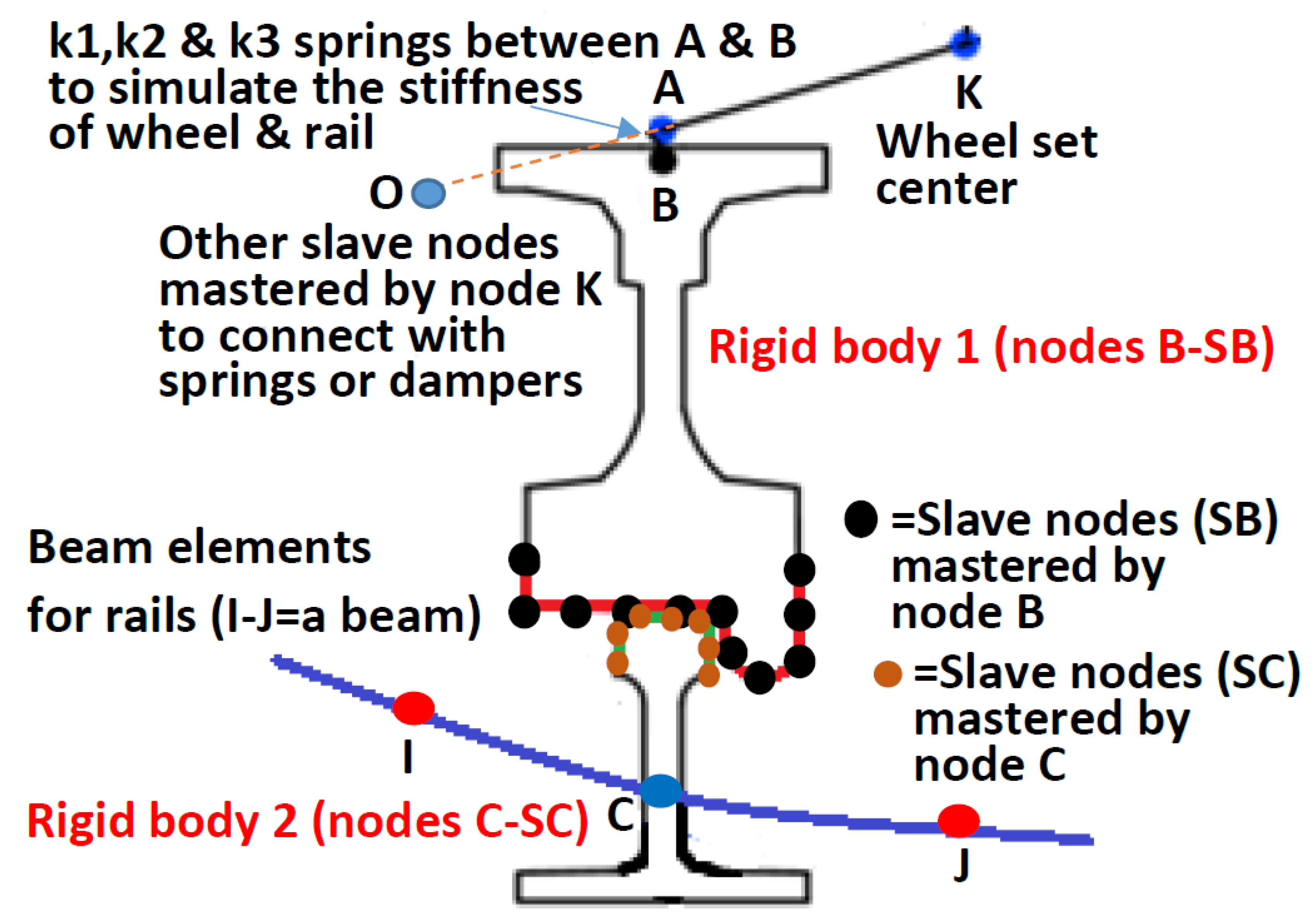
  • As shown in Figure 4, the proposed moving wheel axis element requires to input the possible contact wheel and rail profiles, where slave nodes SB are mastered by node B, and slave nodes SC are mastered by node C. Thus, there are two rigid bodies contacting together according to the Mohr–Coulomb’s friction law mentioned in Section 2.3. Then, k1, k2, and k3, as shown in Figure 2 and Figure 4 are used to simulate the stiffness of the wheel and rail profiles, where k1 and k2 are constant in the lateral and longitudinal directions and k3 is set as the power low (Equation (15)) in the vertical direction. Those parameters can be obtained using the 3D static contact finite element analysis of the actual wheel and rail. Thus, the proposed moving wheel axis element can simulate the sticking, sliding, separation, and multi-point contact behavior between wheels and rails.
  • The element contains 21 DOFs, where six DOFs with three translations and three rotations are set to node I, J, and K, and three translation DOFs are set to node B. The three rotation DOFs of node B and the six DOFs of node A are mastered by node K, while the purpose of the two nodes are used to arrange the location of stiffness k1, k2, and k3, and they will not connect to other elements. Nodes I and J should be connected to a beam element to simulate rails where the wheel is located between that beam. Node K is located at the wheel axle center, and springs and dampers can be connected to it using slave nodes (such as node O). For example, as shown in Figure 5, nodes 301 and 401 are mastered by node 1210 of the wheel axle center, and springs and dampers are then connected between these two nodes to link with the wheel set.
  • Curved rails should be modeled using a number of beam elements, where the known position of the wheel can be used to automatically find the beam element to be located, so that a moving axis element is formed easily. Since the vibration of the train is highly dependent on a smooth rail, the curve rail system should include the straight-line, clothoid, and circular segments for the calculation of the wheel position. The centrifugal forces of the train are directly calculated from Equation (5), but not from the finite element computation, so they are exact without errors.
  • A sub-program of the proposed moving wheel axis element (Figure 4) can be established using the equations in Section 2. This finite element can then be used in combination with other elements to simulate a train traveling on a curved track system, in which only the standard Newmark’s and the Newton–Raphson methods are required in the finite element main program. One may use the beam element to simulate rails and bridges, the plate element to simulate the reinforce concrete slab track system, the soil spring to simulate the ballast track system, the rigid link and lumped mass to simulate trains, and any other element to simulate the certain function of the railway. Finally, using the proposed moving wheel axis element with the above finite element mesh, one can simulate train moving on complicated railway systems without difficult.
  • The simulation error is highly dependent on the used time step length (dt), where the vibration frequency of the analyzed domain larger than 1/(6dt) Hz may cause large errors. It is noted that we assume that a certain frequency vibration can be modeled appropriately at least using six time steps. Thus, one should use an appropriate time step length to perform the proposed finite element analysis.

4. Validations of the Proposed Finite Element Simulations

In this section, a Taiwan high-speed train (SKS-700) carriage on curved rails to validate the proposed finite element method, where the carriage contains two bogies and four wheel sets, as shown in Figure 5, which provides the dimensions, dampers, springs, and masses. In the finite element model, the car bodies, bogies, and wheel sets are assumed to be rigid bodies, where master nodes are set to the mass center, and spring–damper elements set at the slave nodes are used to connect them. Four wheel set elements, as mentioned in Section 2, are arranged to connect to the curved rail with five segments, as shown in Figure 3, where the curve lengths are 500 m for the first straight line, 2000 m for the first clothoid curve, 10,908.3078 m for the circular curve, 2000 m for the second clothoid curve, and 800 m for the last straight line. Since the location of the wheel is known, the wheel and rail contact locations, nodes D (shown in Figure 2), can be determined. Then, using the input geometries of the wheel and rail, as shown in Figure 2, the program will automatically calculate the contact behavior, including the sticking, sliding, and separation modes of each wheel and rail using the equations in Section 2.3 and Reference [16]. Moreover, the deformation at any node will affect the contact result, since all the finite elements are coupled in the numerical analysis. In the finite element analysis, the Newmark’s direct integration method is used with a time step length of 0.01 s, while the nonlinear equation is solved by the Newton–Raphson method.
Figure 6 shows the comparison of the normal and shear contact forces of the wheel and rail between the finite element result and the theoretical result, when the carriage speed is 80 m/s and cant angle constants Ct are 200 and 900 m for two cases. It is noted that the rail curve radius is much larger than the carriage length, so the contact forces of each wheel from the finite element analysis are very similar. This figure indicates that the finite element and theoretical results are almost identical. It is noted that the theoretical solution can be easily obtained from Equations (25) and (26), but the finite element solution undergoes complex calculations, where each time step often requires two to four iterations to reach the convergence of the nonlinear matrix equation.
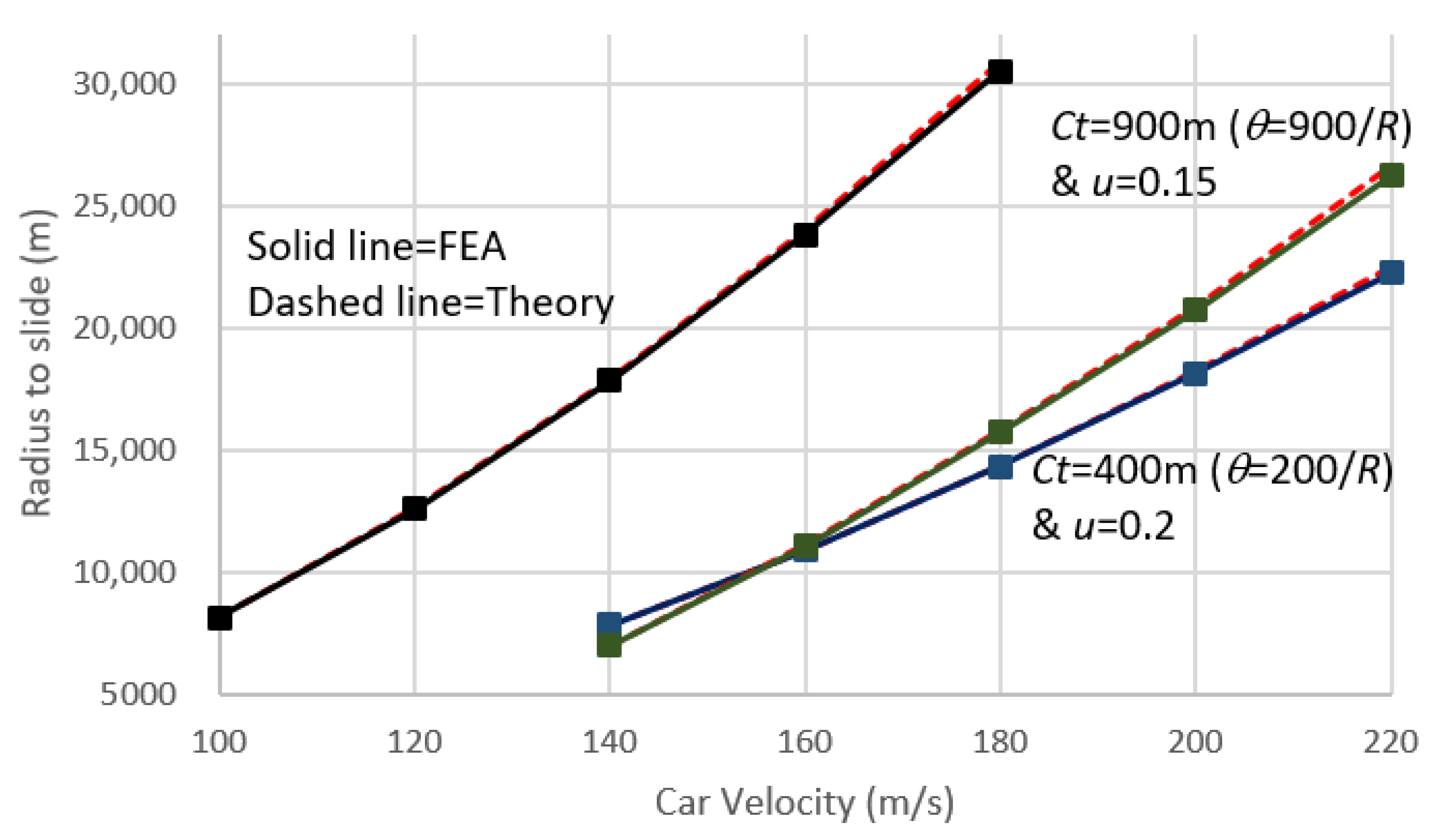
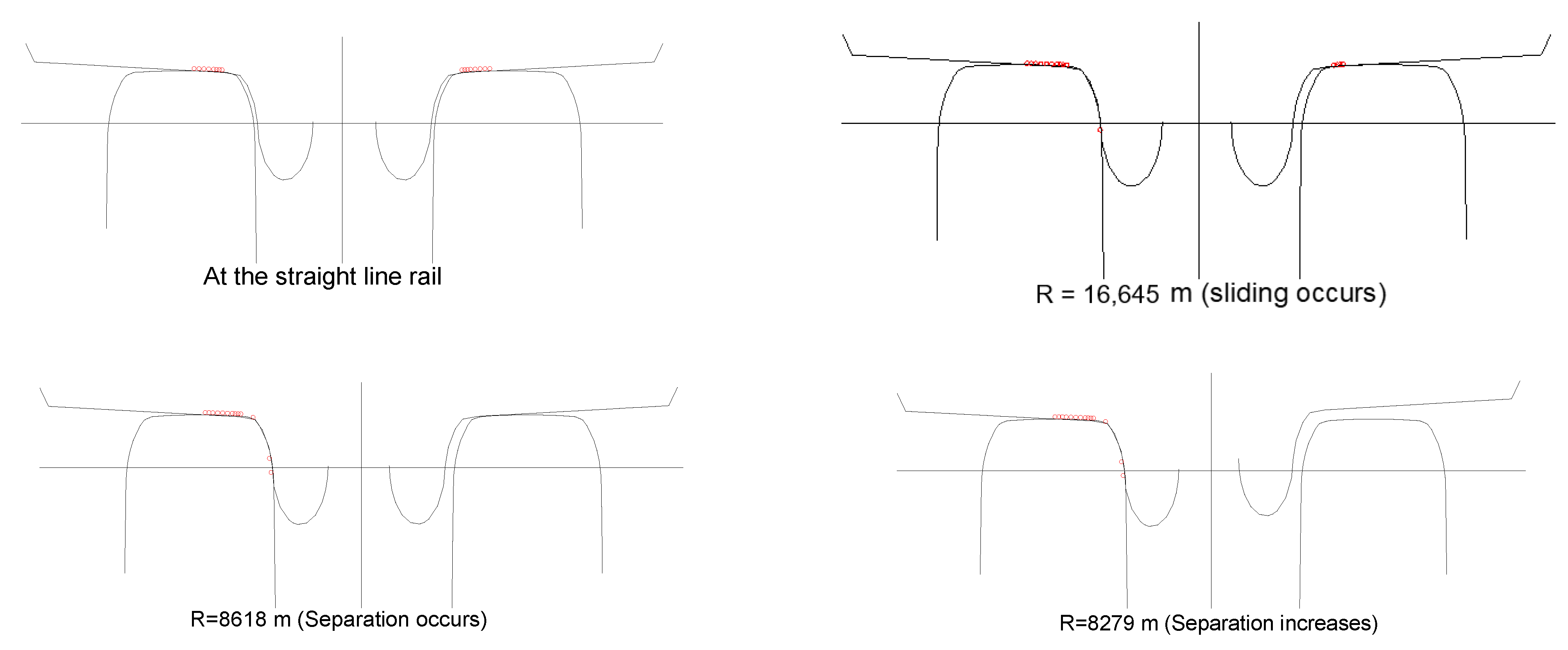
Figure 7 shows the beginning of the sliding between the wheel and rail at a certain curve radius, when the carriage moves on the curved rail with a constant speed. Each symbol in Figure 7 represents a whole finite element analysis, where Equation (24) are used to both theoretical and finite element results automatically to obtain the curve radius under the fixed values of the carriage speed, Ct, and frictional coefficient. The sliding between the wheel and rail can be found in Figure 8, which was directly obtained from the finite element results for Ct = 400 m, V = 180 m/s, and μ = 0.2. It is noted that the wheel and rail shapes, as shown in this figure, are inputted data. The contact is in the sticking mode for a shear contact force smaller than the normal contact force times of the frictional coefficient, and otherwise, the wheel will move toward the outer rail. Figure 7 indicates that the proposed method can accurately be used to simulate the sliding behavior between a wheel and rail under various carriage speed, rail cant, and friction coefficient conditions for the wheel and rail.
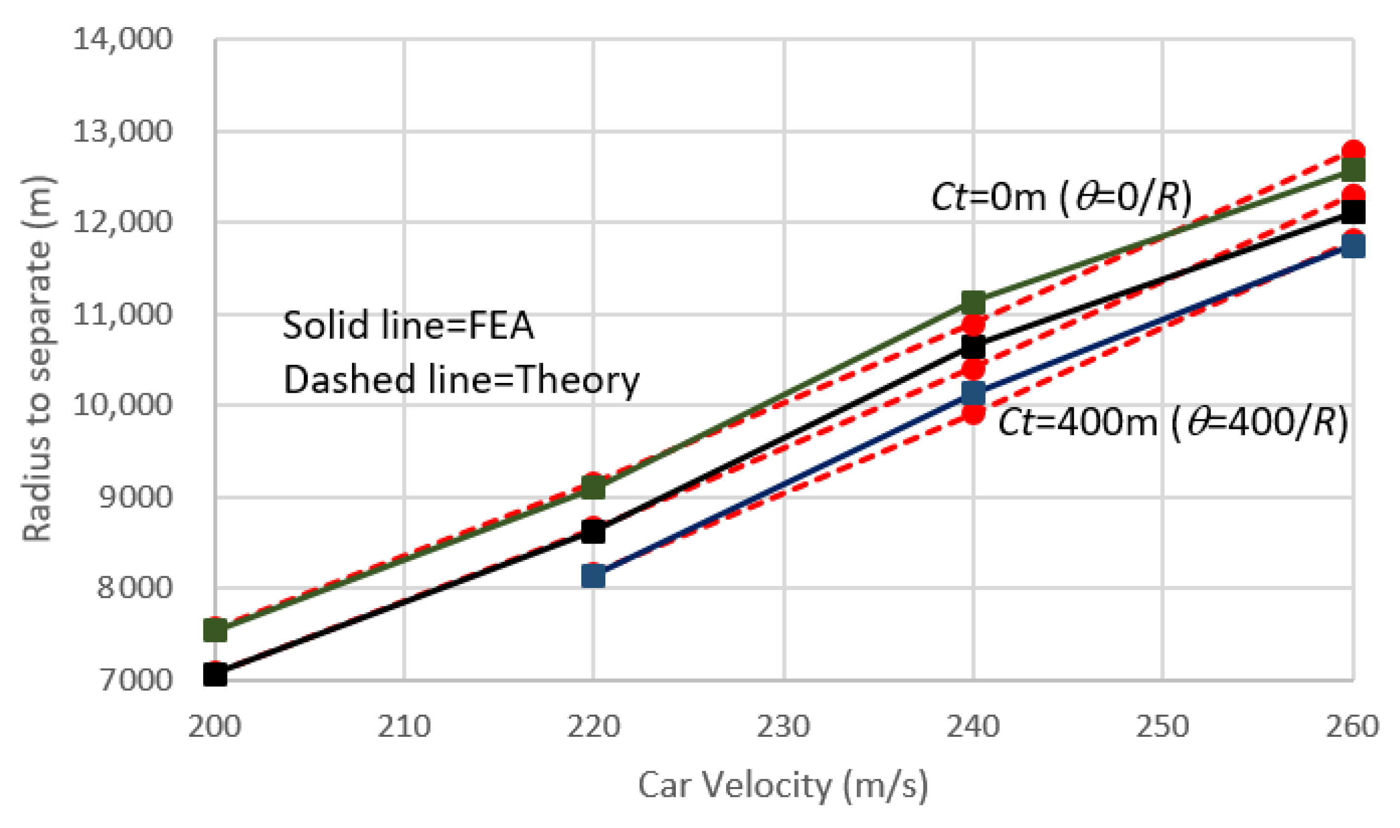
Figure 9 shows the initial separation between the inner wheel and rail at a specific curve radius, when the carriage moves on the curved rail at a constant speed, and where the frictional coefficient between the wheel and rail is set to 0.3. It is noted that the separation of the wheel and rail due to centrifugal force is somewhat dependent on the frictional coefficient. Each symbol in Figure 9 represents an entire finite element analysis, where Equation (25) is used to determine the separation for the theoretical solution, and where the zero normal contact force of the inner wheel and rail from the finite element results was used to automatically obtain the curve radius at fixed values of the carriage speed and Ct. The separation between the wheel and rail can be found in Figure 10, which was directly obtained from the finite element results for Ct = 200 m, V = 220 m/s, and μ = 0.3. When the contact force of the inner wheel and rail equal to zero, the separation of the inner wheel and rail occurs. Figure 9 indicates that the proposed method can accurately simulate the separation behavior between a wheel and rail under different carriage speed and rail cant conditions.
We also performed a complicated finite element analysis for a 12-carriage train moving on multiple simply supported bridges under seismic loads using the proposed method, and the time-history contact force and derailment coefficient of each wheel can be obtained. The finite element mesh, as shown in Figure 11, includes bridges, rails, slabs, and the 12-carriage train, which have 299,668 elements and 1,043,430 degrees of freedom (113 spans with a total length of 3362 m). The time step length is set to 0.0005 s, and the convergence of each time step requires about two to four iterations, where the computer time of each iteration is about 10 s using an Intel-i7-8700K personal computer. This information indicates that the proposed method can be used to analyze finite element model with very large degrees of freedom. Moreover, it can be added to a general nonlinear dynamic finite element code without difficult.

5. Conclusions

The derailment of moving trains has always been an important issue, especially as travel speeds continue to increase. In addition, the reasons for train derailment on curved rails are more complicated than is the case on straight rails. Therefore, in this research, a moving axle element was developed to resolve the contact of the wheel and rail on curved railways, where the sticking, sliding, and separation modes are included. The shape of the wheel and rail along the contact curve is required in the proposed moving axle element, where the normal and tangential stiffness values obtained from a 3D finite element analysis for an actual wheel and rail are used to model the force–displacement relationship. This proposed element can be used to solve the multi-point and wheel flange contact problems on curved rails. Moreover, a finite element case of moving train problems with large degrees of freedom can be analyzed using this method without difficult. For example, we have successfully used this proposed method to analyzed a 12-carriage train traveling on a curved bridge with more than one million degrees of freedom under earthquake loads.
In this paper, numerical validations were performed on a curved rail system with five segments, including a straight line, a clothoid curve, a circular curve, a second clothoid curve, and a second straight line, respectively. A simple two-dimensional theoretical solution was used to validate the finite element results. After comparisons of the contact normal and shear force, sliding situation, and separation situation for a number of train speeds, cant angles, and friction coefficients, the results show good agreement with the theoretical and finite element solutions.

Author Contributions

Conceptualization, methodology, and software were performed by S.-H.J.; validation was down by T.-I.R. All authors have read and agreed to the published version of the manuscript.

Funding

This research was funded by NSC under the grant number: 106-2221-E-006-034-MY3.

Institutional Review Board Statement

Not applicable.

Informed Consent Statement

Not applicable.

Conflicts of Interest

The authors declare no conflict of interest.

References

  1. Pieringer, A. A numerical investigation of curve squeal in the case of constant wheel/rail friction. J. Sound Vib. 2014, 333, 4295–4313. [Google Scholar] [CrossRef] [Green Version]
  2. Zeng, Q.; Dimitrakopoulos, E.G. A three-dimensional dynamic analysis scheme for the interaction between trains and curved railway bridges. Comput. Struct. 2015, 149, 43–60. [Google Scholar]
  3. Zeng, Q.; Dimitrakopoulos, E.G. Seismic response analysis of an interacting curved bridge–train system under frequent earthquakes. Earthq. Eng. Struct. Dyn. 2016, 45, 1129–1148. [Google Scholar] [CrossRef]
  4. Zeng, Q.; Yang, Y.B.; Dimitrakopoulos, E.G. Dynamic response of high-speed vehicles and sustaining curved bridges under conditions of resonance. Eng. Struct. 2016, 114, 61–74. [Google Scholar] [CrossRef]
  5. Han, J.; He, Y.; Xiao, X.; Sheng, X.; Zhao, G.; Jin, X. Effect of Control Measures on Wheel/Rail Noise When the Vehicle Curves. Appl. Sci. 2017, 7, 1144. [Google Scholar] [CrossRef] [Green Version]
  6. Zeng, Q.; Dimitrakopoulos, E.G. Vehicle–bridge interaction analysis modeling derailment during earthquakes. Nonlinear Dyn. 2018, 93, 2315–2337. [Google Scholar] [CrossRef]
  7. Kaewunruen, S.; Ngamkhanong, C.; Liu, X. Spectro-Temporal responses of curved railway tracks with variable radii of arc curves. Int. J. Struct. Stab. Dyn. 2019, 19, 1950044. [Google Scholar] [CrossRef]
  8. Ma, L.X.; Ouyang, H.J.; Sun, C.; Zhao, R.T.; Wang, L. A curved 2.5D model for simulating dynamic responses of coupled track-tunnel-soil system in curved section due to moving loads. J. Sound Vib. 2019, 451, 1–31. [Google Scholar] [CrossRef]
  9. Zhang, D.; Tang, Y.Y.; Clarke, D.B.; Peng, Q.Y.; Dong, C.J. An innovative method for calculating diagonal lashing force of cargo on railway wagons in a curve alignment. Veh. Syst. Dyn. 2019. [Google Scholar] [CrossRef]
  10. Yang, Z.; Li, Z. Numerical modeling of wheel-rail squeal-exciting contact. Int. J. Mech. Sci. 2019, 153, 490–499. [Google Scholar] [CrossRef] [Green Version]
  11. Li, T.; Su, Q.; Kaewunruen, S. Saturated Ground Vibration Analysis Based on a Three-Dimensional Coupled Train-Track-Soil Interaction Model. Appl. Sci. 2019, 9, 4991. [Google Scholar] [CrossRef] [Green Version]
  12. Ma, M.; Xu, L.H.; Du, L.L.; Wu, Z.Z.; Tan, X.Y. Prediction of building vibration induced by metro trains running in a curved tunnel. J. Vib. Control 2020. [Google Scholar] [CrossRef]
  13. Pan, B.; Zhang, W.; Zheng, S.; Zhou, M.L.; Zhao, C.F.; Spencer, B.F. Modelling ambient vibration responses induced by operation of metro train on curved rail segment with small curvature radius. Math. Probl. Eng. 2020, 2020, 1–17. [Google Scholar] [CrossRef] [Green Version]
  14. Lai, V.V.; Chiello, O.; Brunel, J.F.; Dufrenoy, P. The critical effect of rail vertical phase response in railway curve squeal generation. Int. J. Mech. Sci. 2020, 167, 105281. [Google Scholar] [CrossRef]
  15. Lulu, G.B.; Chen, R.; Wang, P.; Xu, J.M.; Chen, J.Y.; Fang, J.S. Random vibration analysis of tram-track interaction on a curve due to the polygonal wheel and track irregularity. Veh. Syst. Dyn. 2020. [Google Scholar] [CrossRef]
  16. Ju, S.H. A frictional contact finite element for wheel/rail dynamic simulations. Nonlinear Dyn. 2016, 85, 365–374. [Google Scholar] [CrossRef]
  17. Kalker, J.J. Variational and non-variational theory of frictionless adhesive contact between elastic bodies. Wear 1987, 119, 63–76. [Google Scholar] [CrossRef]
  18. Sichani, M.S. Wheel-Rail Contact Modelling in Vehicle Dynamics Simulation. Ph.D. Thesis, KTH Royal Institute of Technology, Stockholm, Sweden, 2013. [Google Scholar]
  19. Ju, S.H.; Rowlands, R.E. A three-dimensional frictional contact element whose stiffness matrix is symmetric. J. Appl. Mech. 1999, 66, 460–467. [Google Scholar] [CrossRef]
  20. Ju, S.H. A cubic-spline contact element for frictional contact problems. J. Chin. Inst. Eng. 1998, 21, 119–128. [Google Scholar] [CrossRef]
  21. Ju, S.H. A simple finite element for nonlinear wheel/rail contact and separation simulations. J. Vib. Control 2014, 20, 330–338. [Google Scholar] [CrossRef]
  22. Ro, T.-I. Study on Wheel-Rail Interaction of Moving Trains in Curved Railways. Master’s Thesis, National Cheng-kung University, Tainan, Taiwan, 2020. [Google Scholar]
Figure 1. Picture of a train moving on the curved railway (photo by Shen-Haw Ju) and illustration of the X-Y-Z coordinate (global coordinate), x-y-z (local coordinate), and 1-2-3 (moving wheel coordinate) systems.
Applsci 11 05106 g001
Figure 2. Moving wheel axis element (the shapes of the wheel and rail (slave nodes) near the possible contact region should be inputted, where master nodes B, C, and K having 6 degrees of freedom control the slave nodes).
Applsci 11 05106 g002
Figure 3. A carriage moving on canted rails with five curve segments.
Applsci 11 05106 g003
Figure 4. Sketch drawing of moving axis element on curved track system (the element contains two rigid bodies contacting at the wheel and rail surfaces, where slave nodes SB for the wheel and slave nodes SC for the rail are obtained from the input data. Usually, 30 to 60 nodes for each slave node group are accurate enough to model the possible contact surface. Rails are modeled using a number of beam elements, where the program automatically find the active beam element that the wheel is contacting).
Applsci 11 05106 g004
Figure 5. Three-dimensional model of a carriage of the high-speed train used in the finite element analysis (4 wheel sets, 2 bogies, and one car body).
Applsci 11 05106 g005
Figure 6. The time–history of the normal and shear contact forces of the wheel and rail based on the finite element and theoretical results for a carriage moving on a curved rail at a speed of 80 m/s (the finite element and theoretical results are almost identical, where θ is shown in Figure 3 and Equation (21)).
Applsci 11 05106 g006
Figure 7. The initial sliding between the wheel and rail at a specific curve radius (R) for the clothoid segment at a fixed carriage speed, cant constant, and frictional coefficient (Ct and θ are defined in Equation (21), and u is the friction coefficient).
Applsci 11 05106 g007
Figure 8. Finite element results for the wheel and rail sliding condition showing multi-point contact behavior after the wheel axle moving moves to the outer rail (the wheel interval is shortened to 1.3 m to show the figure clearly, and red circles refer to contact regions).
Applsci 11 05106 g008
Figure 9. The beginning of the separation between the inner wheel and rail at a specific curve radius when the carriage moves on a curved rail at a constant speed (Ct and θ are defined in Equation (21), and friction coefficient is set to 0.3).
Applsci 11 05106 g009
Figure 10. Finite element results for the wheel and rail sliding and separation conditions (Ct = 200 m, V = 220 m/s, and μ = 0.3).
Applsci 11 05106 g010
Figure 11. The finite element mesh of a 12-carriage train moving on multiple simply supported bridge with 299,668 elements and 1,043,430 degrees of freedom.
Applsci 11 05106 g011
Publisher’s Note: MDPI stays neutral with regard to jurisdictional claims in published maps and institutional affiliations.