Article

Modeling and Analysis of a Generic Internal Cargo Airdrop System for a Tandem Helicopter

1
Chinese Aeronautical Establishment, Beijing 100029, China
2
School of Aeronautic Science and Engineering, Beihang University, Beijing 100191, China
*
Author to whom correspondence should be addressed.
Appl. Sci. 2021, 11(11), 5109; https://doi.org/10.3390/app11115109
Submission received: 28 April 2021 / Revised: 23 May 2021 / Accepted: 26 May 2021 / Published: 31 May 2021
(This article belongs to the Section Aerospace Science and Engineering)

Abstract

:
This article describes the results of modeling and analysis of a generic internal cargo system using a discretization method of the vector mechanics. The model can be easily incorporated into a tandem helicopter model and is intended for use of simulation and investigating the problems of flight dynamics, control, etc., both in flight operation loading a cargo and flight operation in the process of airdrops. The model is derived by considering the main descriptions of the cargo, including the linear and rotational dynamics, the kinematics, and the forces and moments acting on the helicopter. A simulation method embedded with a numerical trim algorithm is developed for the complete coupling helicopter/cargo nonlinear dynamics system. The simulation application of the model is illustrated, including the case of flight operation loading a cargo by considering three mass configurations of 3000, 4500, and 6000 kg, and the case of flight operation in the process of airdrops at velocities of 0, 40, 80, 120, and 160 knots. Stabilities of the helicopter in the process of airdrops are also analyzed. The major conclusions drawn are: (i) the tandem helicopter has a good attitude maintaining ability in the whole flight velocity envelope when it conducts a flight operation loading a cargo; (ii) in the process of airdrops, the increase in flight velocity will constantly decrease the helicopter pitching attitude and increases the total airdrop time and decreases the backward moving velocity of the cargo, and helicopter flying at a velocity between 80 and 120 knots might be acceptable; (iii) the stabilities of both the longitudinal and lateral periodic modes are continuing to decrease during the backward movement of the cargo.

1. Introduction

The transport function of transport helicopters mainly includes two methods: external slung-load transport and internal cargo transport. Both of these methods can transport heavy cargos, but the helicopter flight speed for the former method is required to be slow due to the coupling dynamics effects of the helicopter and its slung-load. There is no special requirement for the helicopter flight speed for the latter method, but in the period of internal cargo airdropping, the effects of the moving internal cargo on helicopter flight are complicated, even threatening the safety of flying. Exploring the trim and flight characteristics of helicopter transport operations in the two methods is the basis of designing effective flight control laws and for ensuring the flight safety.
Since the 1960s, most research on helicopters with slung-load have been focused on the modeling and dynamics [1,2,3,4,5,6,7], control [8,9,10,11], and flight test and simulation [12,13], etc. Studies on airdrop have also been considered as an important research field due to the vital role of airdrop in the military and civil fields [14]. Recently, the U.S. Army Combat Capabilities Development Command indicated the importance of developing an airdrop technology and depicted the development of the Airdrop Technology Multi-Operational Simulation (ATMOS) [15]. Early in 1995, Air Force Flight Test Center of USA has conducted a cargo airdropping experiment in order to evaluation the interface between cargo airdrop and the aircraft and to devise a modification for optimizing performance [16]. In 2018, a preliminary computational simulation of the extraction of a standard container express (CONEX) cargo container from an aircraft was conducted [17]. However, most of the airdrop technologies were mainly developed based on a fixed wing transport aircraft, including Low Velocity Airdrop (LVAD) [18,19], Low Altitude Airdrop (LAAD) [20,21,22], Container Delivery System (CDS) [23,24], and Precision Airdrop (PAD) [25,26,27]. Early in 1967, the headquarters of U.S. Army Materiel Command presented airdrop requirements and provided detailed airdrop design criteria [28] in terms of helicopters, but with a lack of detailed theoretical studies on modeling, dynamics, and control. Until 2010, only a control design for small-scale helicopters carrying out airdrop missions was conducted [29]. So far, few studies in the literature have focused on the problems of full-scale helicopters with an airdrop system.
The process of airdrop is a complex multi-body dynamic process. With the cargo moving backward in a helicopter, its center of gravity will shift backward, especially heavy cargo. In this circumstance, the center of gravity would probably exceed the bound, thereby sharply changing the flight characteristics, reducing the stability and the handing qualities and might cause a flight accident. Furthermore, when the cargo rotates around the point of tipoff and is going to leave the helicopter, the force and moment provided by the cargo acting on the helicopter may become more complex. In 2019, some dynamic characteristics of a single rotor helicopter under heavy cargo airdrop condition were conducted [30], with the conclusions that the forward flight airdrop has a better attitude maintaining ability, compared with the hovering airdrop.
The main methods used for modeling a cargo airdrop system are the analytical mechanics method [31] and the vector mechanics method [32]. The former method is based on the study of work and energy. The latter method is based on the study of vector and is more visualized, thus it is widely used. The vector mechanics method is also classified as the overall method [33,34] that makes the instantaneous mass center of the airplane–cargo system as the reference point, and the separation method [35,36,37] that considers the mass center of the airplane as the reference point. The dynamics equation of the overall method is relatively simple, but because of the incessant change of reference points, the solution is complicated. Since the reference point of the separation method is fixed, the calculation of the force and moment of the cargo in the helicopter is clearer, and it is convenient to study the flight dynamics characteristics of helicopters in the process of cargo airdrop.
For the research of the helicopter internal cargo airdrop, this article uses the above separation method, but with some novelty; it mainly refers to the research method of the cargo airdrop of the fixed wing conveyer [36], and involves the difference between the helicopter cargo airdrop and the fixed wing conveyer cargo airdrop. The dynamics modeling of the fixed wing conveyer cargo airdrop is mainly in focus on the force acting on the aircraft before the airdrop leaves the aircraft. However, there is less consideration on the sharp change in the force acting on the fuselage when the cargo is dropped at the end of the cabin. In order to study the effect of the cargo on the helicopter trim and stability from the beginning of the movement away from the cabin to the complete departure from the cabin room, this article has completed the dynamic modeling analysis of the process of the helicopter cargo airdrop.
The main research content of this article is to present a methodology of CH-47 series tandem rotor helicopter flight dynamics model under heavy cargo airdrop conditions in order to analyze the trims and stabilities. The article is organized as follows. First, a cargo airdrop model is proposed. Following this, a tandem rotor helicopter flight dynamics model under heavy cargo airdrop condition is established. The trim algorithm and simulation method are developed. Verification of the flight dynamics model has been conducted. The trim characteristics analysis of the helicopter/cargo system is conducted. Stability features of the tandem rotor helicopter in the process of airdrop are also analyzed thoroughly.

2. Internal Cargo Airdrop System

The general fixed-wing transport aircraft extracts the internal cargo from the cabin using a recovery parachute during airdropping. Due to the low flight speed of the helicopter, especially the influence of the downwash generated by the main rotor, the recovery parachute, if used for helicopter internal cargo airdrops, is difficult to open smoothly. This is the practical difference between the helicopter airdrop and the fixed-wing aircraft airdrop. Thus, usually combining with both the manpower and sliding rails, the cargo can be extracted from the helicopter cabin. Generally, two workers are employed to push the cargo that is installed on the sliding rails.
In this article, a generic internal cargo airdrop system using both manpower and sliding rails for a CH-47 series tandem rotor helicopter is studied. The cargo compartment of the helicopter, with a length of 366 in. (9.2964 m), width of 90 in. (2.286 m), and height of 78 in. (1.9812 m), has an internal load capacity of 16000 pounds (7257.5 kg) at helicopter maximum gross weight of 33,000 pounds (14,968.6 kg) [28]. A rectangular container, with a length of 2.6 m, width of 2 m, height of 1.4 m, and mass of 3000 kg, is selected as a basic cargo configuration, assuming that the cargo is in the longitudinal symmetry plane of the helicopter with no lateral movement, and the initial position of the cargo is directly under the center of gravity of the helicopter.
Considering the general non-uniform distribution of the mass of the cargo, we develop a discretization method of the separation method of the vector mechanics in order to analyze this generic internal cargo airdrop system. Compared with the traditional separation method, our method has some novelty. In detail, by using the discretization method, the cargo can be divided into N discrete sections along the longitudinal moving direction. After analyzing the working condition in each section and synthesizing all the sections, a novel cargo airdrop analysis technique can be developed. Figure 1 shows the sketch of this analysis technique. Some of the aspects are considered thoroughly as follows, including the descriptions of the linear and rotational dynamics of the cargo, the kinematics of the cargo, and the forces and moments of the worker–cargo system acting on the helicopter.

2.1. Linear Dynamics Descriptions

Using the separation method of the vector mechanics, the forces act on the backward moving cargo are the gravity of itself ( m L g ), the pushing force provided by the two workers ( F P ), and the supporting force ( N B ) and frictional force ( f B ) provided by the helicopter. Further using the discretization method, the gravity of the ith discrete section of the cargo in its own body axis system ( o x L y L z L ) is written as follows:
[ Δ F L , x i Δ F L , y i Δ F L , z i ] = T ( θ L ) · T ( ϕ B ) · T ( θ B ) [ 0 0 ρ L i · Δ l · g ]
where Δ F L ,   x i , Δ F L ,   y i , and Δ F L ,   z i are the gravitational components of the ith discrete section of the cargo in the cargo body axis system ( o x L y L z L ), T ( · ) the Euler transformation matrix, θ B , ϕ B , and ψ B the respective pitching, rolling, and yawing attitude angles of the helicopter, ρ L i the linear density of the mass of the ith discrete section of the cargo, Δ l the length of each discrete cargo section, and g the gravitational acceleration.
In Equation (1), Δ F L ,   z i also represents the normal supporting force of the ith discrete section of the cargo provided by the helicopter. Thus, the whole normal supporting force ( N B ) and frictional force of the backward moving cargo ( f B ) can be written as follows:
{ N B = i = 1 N Δ F L , z i f B = i = 1 N ( Δ F L , z i + | Δ F L , y i | ) · μ
where N is the total number of the discrete sections of the cargo, and μ the equivalent coefficient of the friction between the cargo and the sliding rails. N B 0 indicates that the cargo has left the helicopter, which can be taken as the first exit condition of the simulation.
The basic equation of the linear dynamics of the moving cargo in the process of exaction from the helicopter cabin can be deduced as follows:
V ˙ L = [ F P σ ( V L ) · f B i = 1 N Δ F L , x i ] / m L
where V L is the backward moving velocity of the cargo, F P the pushing force provided by the workers acting on the cargo, and m L the mass of the cargo. V L < 0 indicates that the airdrop operation is failed, which can be taken as the second exit condition of the simulation. The symbolic function σ ( V L ) can be defined as follows:
σ ( V L ) = { V L | V L | ,       V L 0 1         ,       V L = 0
Theoretically, each worker can provide a maximum force of 1000 N to push the cargo [38]. Considering some of the possible unexpected factors, however, we assume that each worker provides 80% of the maximum pushing force. In addition, we also assume that when the cargo is going to rotate around the point of tipoff, the two workers withdraw the pushing force immediately. Thus, we can let F P = 0 in this circumstance.

2.2. Rotational Dynamics Descriptions

Under the action of the linear dynamics of the cargo, the cargo will move to the point of tipoff, and it is going to rotate around the point of tipoff once the up-pitching moment of the cargo around the point of tipoff is generated. Thus, the basic equation of the rotational dynamics of the cargo can be written as follows:
θ ¨ L = M P / J P
where θ L is the rotational angle of the cargo around the point of tipoff, J P the moment of inertia of the cargo around the point of tipoff, and M P the up-pitching moment of the cargo around the point of tipoff in the cargo body axis system ( o x L y L z L ), which can be deduced as follows:
M P = i = 1 N 1 2 H · Δ F L , x i i = 1 N D i ( t ) · Δ F L , z i
where H is the height of the cargo, and D i ( t ) the longitudinal distance between the center gravity of the ith discrete section of the cargo and the point of tipoff in the cargo body axis system ( o x L y L z L ). It is determined by the cargo kinematics. M P < 0 indicates that the cargo has not yet moved to the point of tipoff, which is θ L = 0 . Thus, we can let M P = 0 in this circumstance.
According to the parallel axis theorem of the moment inertia, J P is deduced as follows:
J P = i = 1 N 1 12 ρ L i · Δ l · [ Δ l 2 + 5 4 H 2 + D i ( t ) · D i ( t ) ]

2.3. Cargo Kinematics Descriptions

Cargo kinematics can be defined as the description of the backward moving cargo mainly using two basic concepts: distance and time. With the cargo moving backward in the helicopter, the basic equation of the cargo kinematics can be written as follows:
D ( t ) = D 0 + L / 2 0 t V L d t
where D ( t ) is the longitudinal distance between the cargo ends close to the workers and the point of tipoff in the cargo body axis system ( o x L y L z L ), D 0 the longitudinal distance between the center gravity of the helicopter and the point of tipoff in the helicopter body axis system ( o x B y B z B ), and L the length of the cargo.
In Equation (8), D ( t ) < 0 indicates that the cargo has left the helicopter which can be taken as the third exit condition of the simulation. Thus, the longitudinal distance D i ( t ) is deduced as follows:
D i ( t ) = D ( t ) [ 1 2 Δ l + ( i 1 ) Δ l ]
Thus, the longitudinal distance S i ( t ) can be deduced as follows:
S i ( t ) = D 0 D i ( t )
where we can let S i ( t ) = D 0 when the cargo begins to rotate around the point of tipoff. This is because the contact area between the moving cargo and helicopter has changed into a point of tipoff in this circumstance.
In a similar manner, the longitudinal distance S ( t ) can be deduced as follows:
S ( t ) = D 0 D ( t )
where we assume that the longitudinal distance between the workers and cargo is so close that it can be negligible. In addition, we can let S ( t ) = D 0 D ( t tipoff ) after the cargo rotates around the point of tipoff.

2.4. Forces and Moments Acting on the Helicopter

We mainly discuss the forces and moments of the worker–cargo system acting on the helicopter according to the principle of the biomechanical analysis of fundamental human movements [38]. Using the separation method of vector mechanics, the frictional forces of the worker–cargo system act on the helicopter are written as follows:
{ F P = F P f L = f B
where F P is the frictional force provided by the workers acting on the helicopter, and f L the frictional force provided by the cargo acting on the helicopter.
Two types of the flight operation are considered, including the helicopter flight operation carrying an internal cargo and the helicopter flight operation in the process of the cargo airdrop.
  • In the first type of the flight operation, the cargo is stationary relative to the helicopter. Thus, we can let F P = 0 in this circumstance. The gravity of the ith discrete section of the cargo acting on the helicopter in the helicopter body axis system ( o x B y B z B ) can be written as follows:
    [ Δ X L ,   B i Δ Y L ,   B i Δ Z L ,   B i ] = T ( θ L ) [ Δ F L , x i Δ F L , y i Δ F L , z i ]
  • In the second type of the flight operation, the cargo is moving backward and airdropping. Thus, the forces of the ith discrete section of the cargo acting on the helicopter in the helicopter body axis system ( o x B y B z B ) can be written as follows:
    [ Δ X L ,   B i Δ Y L ,   B i Δ Z L ,   B i ] = T ( θ L ) [ σ ( V L ) · f L i Δ F L , y i Δ F L , z i ]
Thus, the resultant force vector of the cargo acting on the helicopter in the above two types of the flight operations can be written as follows:
F L = i = 1 N [ Δ X L ,   B i Δ Y L ,   B i Δ Z L ,   B i ] + T ( ϕ B ) · T ( θ B ) [ 0 0 m P · g ] + [ F P 0 0 ]
where m P is the mass of the workers.
The resultant moment vector of the cargo acting on the helicopter in the above two types of the flight operations is written as follows:
M L = i = 1 N { [ S i ( t ) 0 h ] × [ Δ X L ,   B i Δ Y L ,   B i Δ Z L ,   B i ] } + [ S ( t ) 0 h ] × { T ( ϕ B ) · T ( θ B ) [ 0 0 m P · g ] + [ F P 0 0 ] }
where h is the vertical distance between the center gravity of the helicopter and its cabin floor in the helicopter body axis system ( o x B y B z B ). The terms of the right hand of the equation represent the moment provided by the cargo and the workers, respectively.

3. Flight Dynamics Model

3.1. Basic Model Descriptions

In Section 2, the interaction forces and moments between the cargo and the helicopter during the process of the cargo airdrop are obtained. They are represented by F L and M L , respectively. These can be incorporated into the tandem rotor helicopter flight dynamics model
{ m B V ˙ B + m B ω B × V B = F B H ˙ B + ω B × H B = M B                     ω B = T Euler [ θ ˙ B ,   ϕ ˙ B ,   ψ ˙ B ] T    
where m B is the mass of helicopter, V B the vector of the helicopter velocity, ω B the helicopter angular velocity, H B the vector of the angular momentum of the helicopter in the helicopter body axis system ( o x B y B z B ), and T Euler the Euler Transmission matrix.
In the above formula, the resultant force vector ( F B ) and resultant moment vector ( M B ) acting on the helicopter can be written as:
{ F B = F RF + F RR + F FUS + F G + F L M B = M RF + M RR + M FUS + M L
where the aerodynamic force and moment vectors of the front and rear rotors ( F RF , F RR , M RF , M RR ) are estimated using the Rotor Momentum Theory [39]. The aerodynamic force and moment vectors of the fuselage ( F FUS , M FUS ) are estimated by linear interpolation using the wind tunnel test data [40,41]. The test was conducted using a rotor-off fuselage at the conditions of different fuselage angle of attack and sideslip angle, both with range from −90 to 90 degrees. Because the Reynolds number in the test was not available, the data were normalized by fuselage dynamic pressure in order to be widely used in different flight conditions.

3.2. Trim Algorithm

In this article, the trim algorithm developed here is based on the Levenberg–Marquardt algorithm for nonlinear least-squares minimization [42]. The thought of the trim process is to solve the nonlinear system equation for under a steady state condition. The Equation (17) represents such a nonlinear dynamics system equation:
χ ˙ = g H ( χ , U )
where g H ( · ) is the symbolic function, χ the state vector, and U the vector of the pilot control input of the tandem rotor helicopter. The purpose of the trim process is to solve the minimization problem
min χ ˙ = g H ( χ , U )
The state vector of the tandem rotor helicopter can be written as:
χ = [ u B ,   v B ,   w B , p B ,   q B ,   r B , θ B ,   ϕ B ,   ψ B ] T
where u B , v B , and w B are the longitudinal, lateral, and vertical velocities of the helicopter in the helicopter body axis system ( o x B y B z B ), and p B , q B , and r B the rolling, pitching, and yawing angular velocities of the helicopter in the helicopter body axis system ( o x B y B z B ).
The input vector is:
U = [ δ B , δ C , δ S , δ R ] T
where δ B , δ C , δ S , and δ R are the longitudinal cyclic, thrust, lateral cyclic, and pedal controls in the cockpit of helicopter.

3.3. Simulation Method

By combining Formulae (3), (5) and (8), the internal cargo airdrop system represents such a nonlinear dynamics system equation
Y ˙ = g L ( t , θ B ,   ϕ B ,   Y )
where g L ( · ) is the symbolic function. The state vector Y can be written as:
Y = [ θ L ,   θ ˙ L ,   V L , D ( t ) ] T
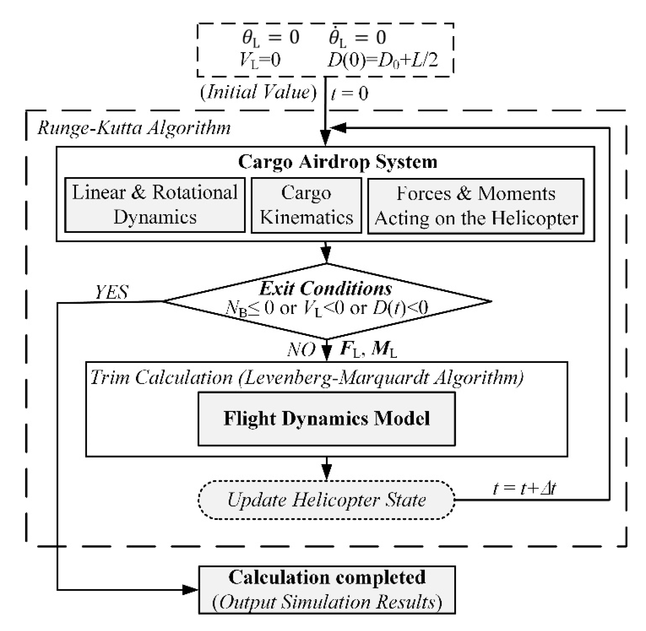
Two nonlinear dynamics system equations, such as Formulae (19) and (23), are coupled with each other due to θ B and ϕ B . It makes the simulation complicated. Considering a steady hovering flight or a straight level flight of constant velocity in most practical airdrop cases, we can assume that the state vector of the helicopter is under a steady state condition during the extraction phase of an internal cargo airdrop. Thus, we can adopt the Runge–Kutta algorithm [43] with the trim calculation incorporated to conduct the simulation. At each step of the Runge–Kutta algorithm, F L and M L are embedded in the helicopter flight dynamics model as a function of θ B and ϕ B in order to trim the helicopter. In addition, three exit conditions are used to control the stop of the simulation. Figure 2 shows the implementation procedure of the simulation.
At the beginning of the simulation, the cargo is going to move backward and has not rotated around the point of tipoff. Thus, we can let θ L = 0 and θ ˙ L = 0 as the initial values. In addition, we can also let V L = 0 and D ( 0 ) = D 0 + L / 2 as the initial values for the simulation.

4. Trim Analysis

To validate and illustrate the present model, the following simulation cases are presented.

4.1. Case of Helicopter Flight Operation Loading an Internal Cargo

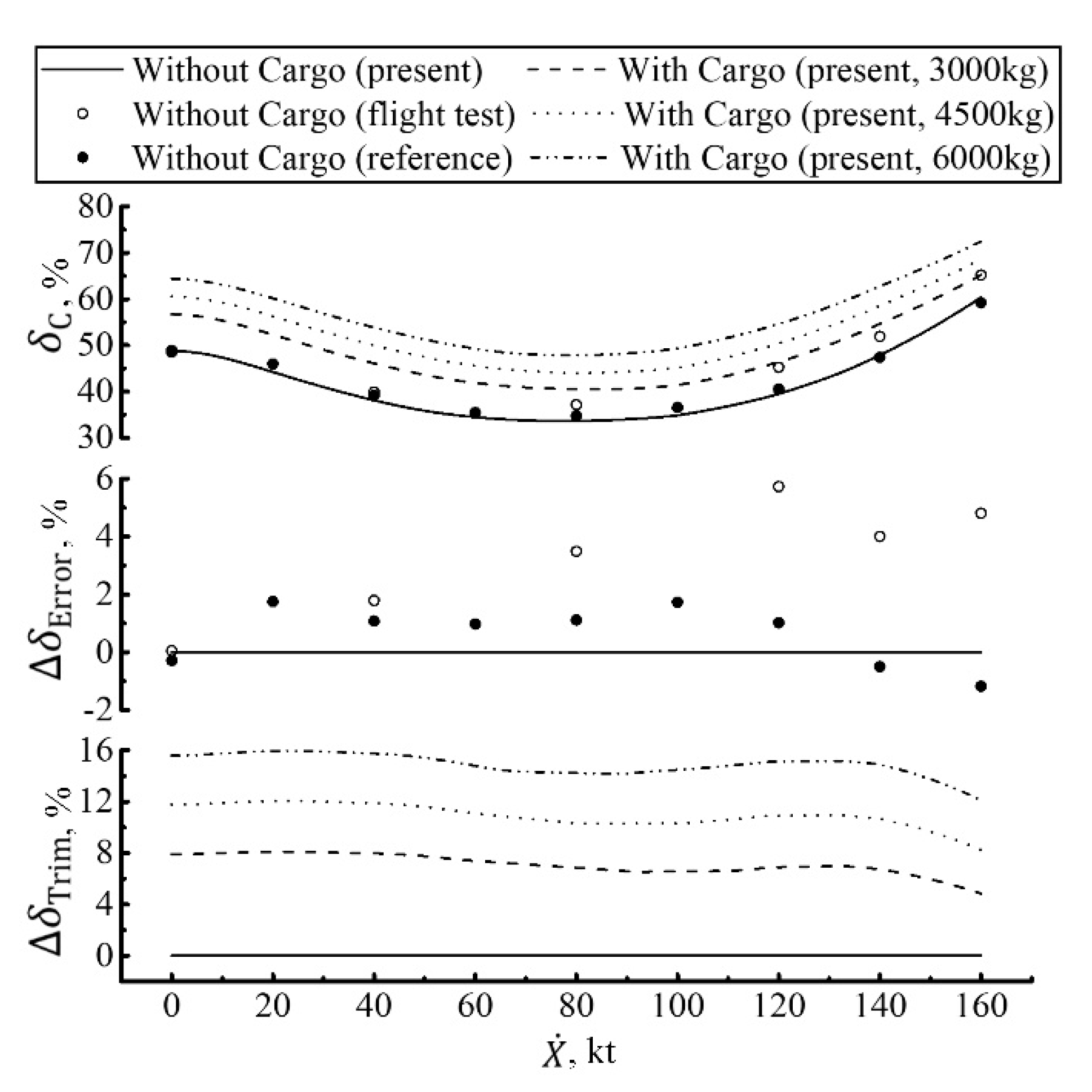
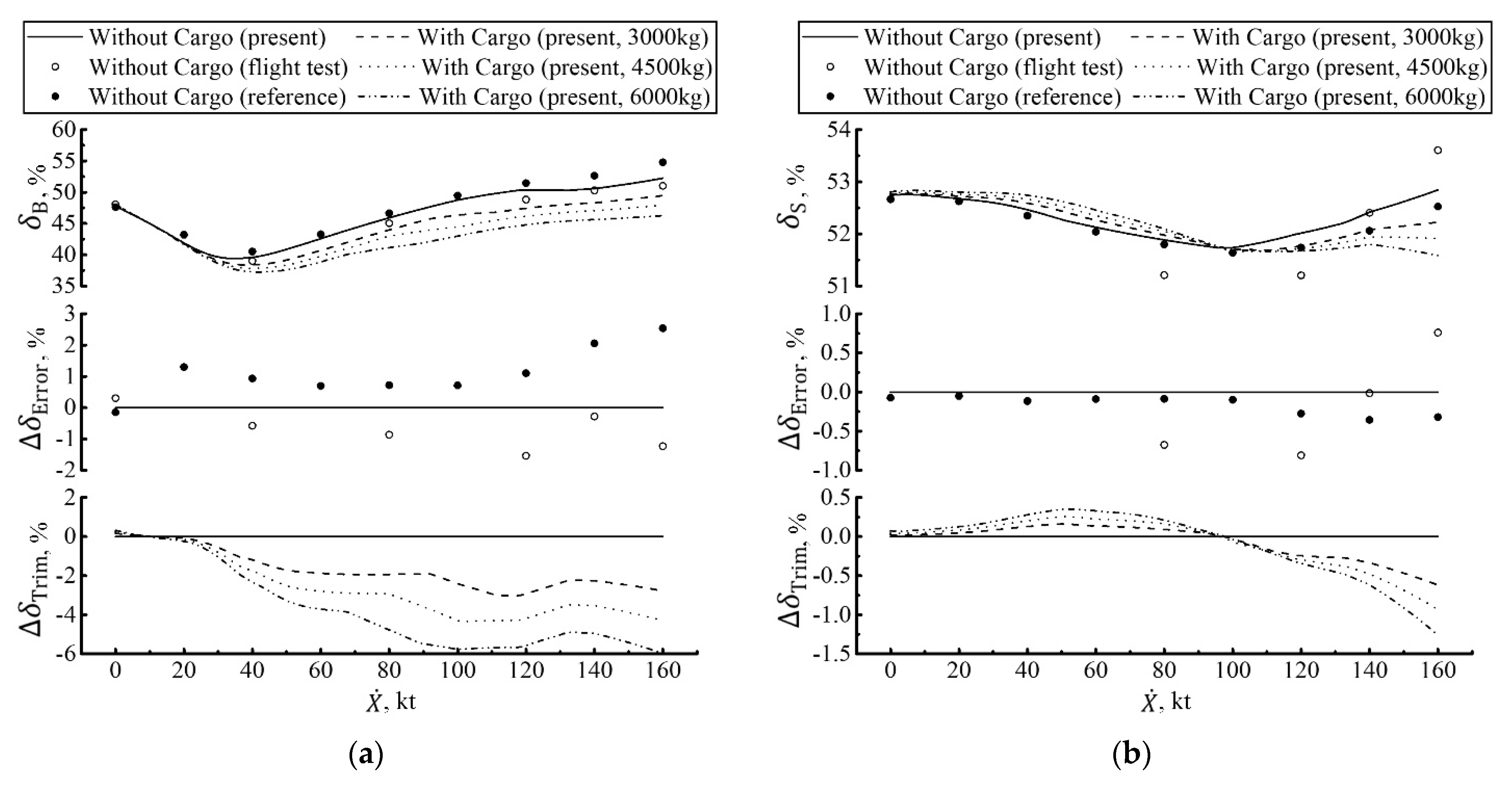
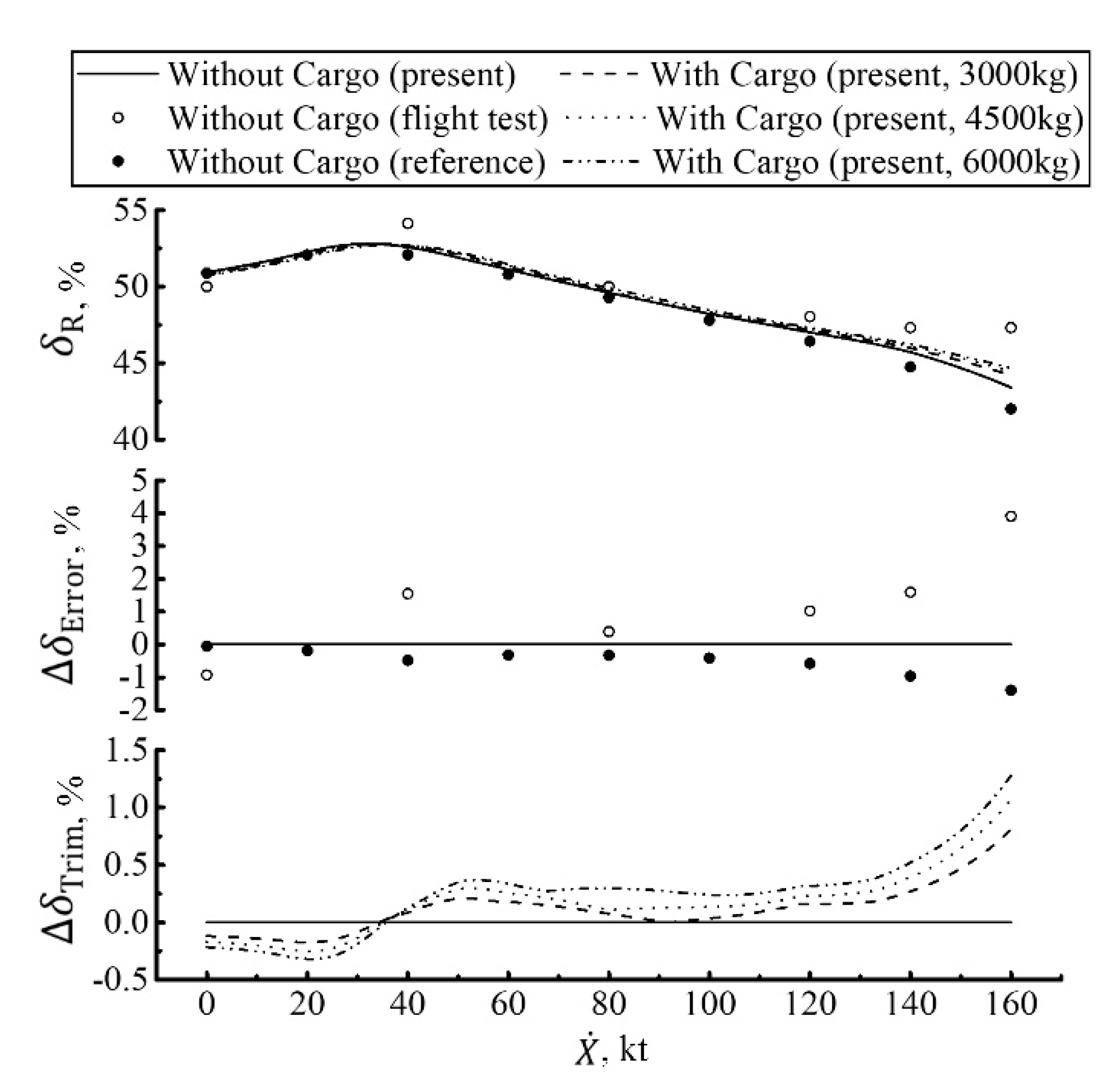
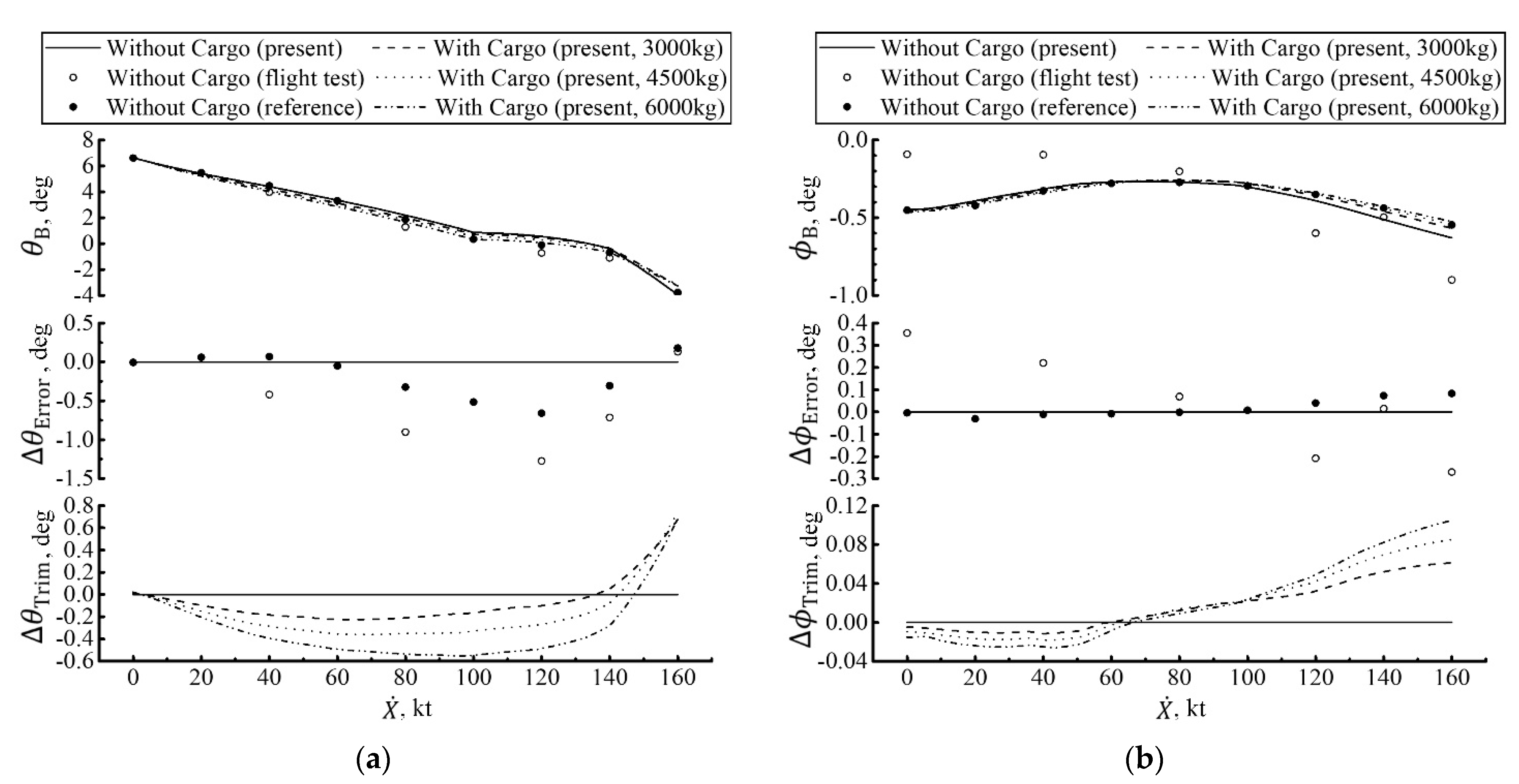
Trim analysis of CH-47B tandem rotor helicopter flying with an internal cargo, with the mass of 3000 kg, 4500 kg, or 6000 kg, is numerically conducted. The flight dynamics model for CH-47B tandem rotor helicopter without internal cargo has been preliminary validated [44]. Here, more detailed work is conducted in Figure 3, Figure 4, Figure 5 and Figure 6. Trim results of the thrust, cyclic and pedal controls, and the pitching and rolling attitude angles are compared with the flight test data [45] and the reference data [40]. Error deviations relative to the flight test data and the reference data and trim deviation relative to the case of helicopter flight operation without internal cargo are also presented.
As shown in Figure 3, Figure 4, Figure 5 and Figure 6, the present trim results of helicopter flying without internal cargo are in good agreement with the flight test data and the reference data. Thus, it can be concluded that the present model and methodology are suitable for this study. In detail, the maximum trim errors of the thrust, longitudinal/lateral cyclic and pedal controls are less than 6.0%, 3.0%, 1.0%, and 4% of travels, respectively. The maximum trim errors of the pitching and rolling attitude angles are less than 1.5 deg and 0.4 deg, respectively. Furthermore, the present trim results match with the reference data much better than the flight test data. The probable reason might be that the present flight dynamics model uses the Rotor Momentum Theory (RMT) to simulate the twin-rotor aerodynamics. Because the RMT assumes that the flow through the rotor is one-dimensional, quasi-steady, incompressible, and inviscid, but the actual physical flow about the twin rotors comprise a complicated wake structure, thus the RMT can hardly catch the twin-rotor aerodynamic phenomena, including the aerodynamic interaction of twin rotors and the aerodynamic interaction of rotor/fuselage, etc. Using the Free-Vortex System or Computational Fluid Dynamics (CFD) method to simulate the twin-rotor aerodynamics may improve the present trim data.
By comparing with the trim results of helicopter flight operation with/without internal cargo, it can be drawn as follows:
  • Flight operation loading an internal cargo mainly evidently affects the trim positions of the thrust and longitudinal cyclic controls, especially flying at a large flight velocity, as shown in Figure 3 and Figure 4a. In detail, it decreases the trim position of the longitudinal cyclic control, except for hovering and flying at a low flight velocity less than 10 knots. It also increases the trim position of the thrust control due to the mass of the cargo. In addition, the increase in the mass of the cargo would decrease the trim position of the longitudinal cyclic control and further increase the trim position of the thrust control. Taking the trim results of the helicopter that flies with a cargo of 6000 kg as an example, the maximum negative trim deviation of the longitudinal cyclic control reaches by −6% of the travel and the maximum positive trim deviation of the thrust control by +16% of the travel.
  • In most practical applications, the internal cargo is generally set in the longitudinal symmetry plane of the helicopter with no lateral movement; thus, there is a small effect on the trim positions of the lateral cyclic and pedal controls, as shown in Figure 4 and Figure 5. In detail, compared with the trim results of helicopter flying without internal cargo, the maximum change in the trim positions of the lateral cyclic and pedal controls with internal cargo (maximum mass of 6000 kg) is less than 1.5%. However, there are some interesting changes in the trim position of the lateral cyclic control. It is that flight operation loading an internal cargo increases the trim position of the lateral cyclic control at a flight velocity less than 100 knots, and decreases the trim position of the lateral cyclic control at a flight velocity higher than 100 knots. These might be related to the changes in trim position of the rolling attitude angles at different flight velocities.
  • In Figure 6, within the helicopter flight velocity envelope, flight operation loading an internal cargo has a slight effect on the trim positions of the pitching and rolling attitude angles. It indicates that the tandem rotor helicopter has a good attitude maintaining ability in the whole flight velocity envelope when the helicopter conducts airdrops. Maybe this is the right reason for which the tandem rotor helicopter is more suitable for conducting internal cargo transport compared with the conventional single rotor helicopter.

4.2. Case of Helicopter Flight Operation in the Process of Internal Cargo Airdrops

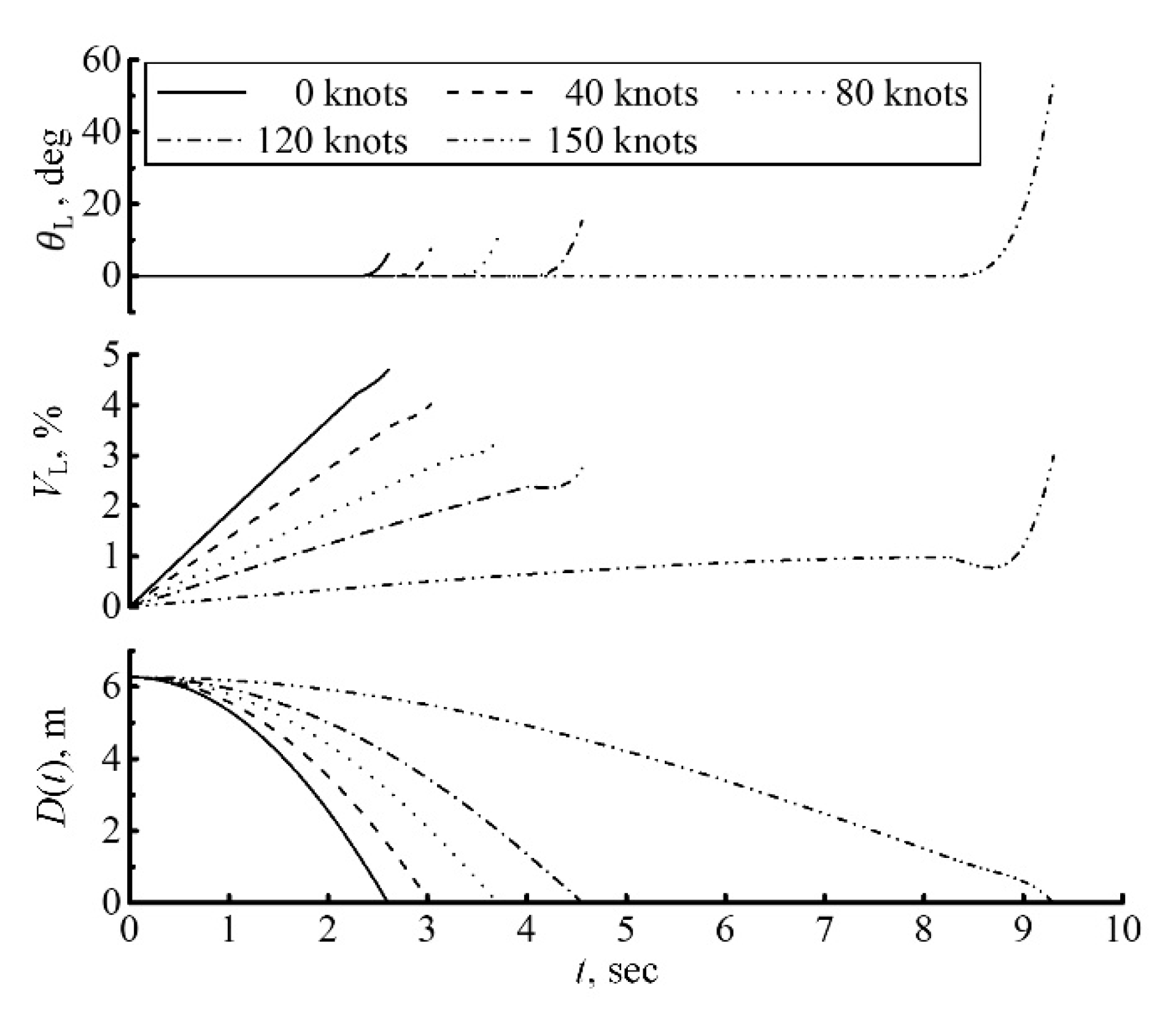
Simulation of CH-47B tandem rotor helicopter flight operation in the process of internal cargo airdrops at the flight velocities of 0, 40, 80, 120, and 150 knots were conducted. Figure 7 shows the simulation results of the main parameters related to the internal cargo. The detailed simulation results of the thrust, cyclic and pedal controls, and the pitching and rolling attitude angles are presented in Figure 8, Figure 9, Figure 10 and Figure 11. The trim deviations relative to the initial trim state are also plotted in order to analyze the effects of the internal cargo airdrop on helicopter flight.
According to the simulation of helicopter flying from 0 knots to 150 knots, the total airdrop time is between 2.6 and 9.3 s, the maximum backward moving velocity of the cargo reaches by 4.7 m/s at hovering, and the maximum rotational angle of the cargo around the point of tipoff reaches by 54.48 deg at the flight velocity of 150 knots. The increase in flight velocity will constantly decrease the helicopter pitching attitude angle, thus increases the total airdrop time and decreases the backward moving velocity of the cargo. Theoretically, the shorter the total airdrop time, the better, because the influence of the airdrop operation on the flying helicopter will be smaller and smaller. However, considering the actual influence of the high speed of the moving cargo on the worker’s safety, there might be a limit of the moving velocity of the cargo. Thus, tandem rotor helicopter flying at a velocity between 80 and 120 knots might be acceptable in the practical application.
As seen in Figure 8, Figure 9, Figure 10 and Figure 11, in order to keep the helicopter flying smoothly during the internal cargo moving backward, the pilot should constantly decrease the longitudinal cyclic control and increase the lateral cyclic and pedal controls and slightly hold the thrust control. Once the cargo begins to rotate around the point of tipoff, the thrust control should be decreased softly. Note that, after this moment, we need to pay attention to some of the other details, as follows:
  • The longitudinal cyclic control should be continuously decreased when the helicopter flies at the velocity of less than 120 knots, and be decreased firstly and then increased when the helicopter flies at the velocity of 150 knots.
  • The lateral cyclic control should be continuously increased when the helicopter flies at the velocity of less than 40 knots, and be decreased when the helicopter flies at the velocity between 80 and 120 knots, and be decreased firstly and then increased when the helicopter flies at the velocity of 150 knots.
  • A slight adjustment of the pedal control should be made in order to trim the helicopter.
The complex changes in the forces and moments of the backward moving cargo acting on the helicopter might be contributed to these changes in the thrust, cyclic, and pedal controls, especially the changes in the cyclic control. Considering the obvious reverse travel control of the longitudinal and lateral cyclic controls after the cargo rotates around the tipoff, it is not suggested to conduct the internal cargo airdrop operation when the helicopter flies at a high velocity such as 150 knots. This may increase the pilot’s control load and may even degrade the helicopter’s flying qualities.
An additional interesting analysis can be conducted as follows:
  • The airdrop operation significantly decreases the trim position of the longitudinal cyclic control within the helicopter flight velocity envelope flight operation, and significantly decreases the thrust control when the helicopter flies at the velocity of 150 knots. In detail, the negative maximum of the trim deviations from the initial trim state of the longitudinal cyclic and thrust controls reach by about 15% and 25%, respectively. These are because the pitching moment acting on the helicopter would increase gradually when the cargo is moving backward. Furthermore, when the cargo starts to rotate around the tipoff, because the pitching moment acting on the helicopter decreases quickly, the trim positions of the longitudinal cyclic and thrust controls have an obvious trend of returning to the trim state of flight operation without cargo.
  • The increase in flight velocity will evidently increase the influence of the airdrop operation on the thrust control and the pitching attitude when the helicopter flies at a velocity between 0 and 150 knots, and evidently decrease the influence of the airdrop operation on the lateral cyclic and pedal controls when the helicopter flies at a velocity of less than 120 knots.
  • The airdrop has a little effect on the rolling attitude. In detail, the maximum of the deviation from the initial trim position of the rolling attitude angle is less than 0.1 deg.

5. Stability Analysis

The present model can also simulate and analyze the stabilities of the tandem rotor helicopter in the process of airdrop using the analysis method of stability [44]. The open-loop dynamics of the CH-47 series tandem rotor helicopter mainly include two longitudinal aperiodic modes (the longitudinal velocity and pitch mode, and the heave-pitch mode) and one longitudinal periodic mode (the phugoid mode), and two lateral aperiodic modes (the roll mode, and the spiral mode) and one lateral periodic mode (the dutch-roll mode) [46]. Simulation results of these modes at helicopter flight velocities of 0, 40, 80, 120, and 150 knots are shown in Figure 12, Figure 13 and Figure 14, in which the effects of airdrop on the stability of the tandem rotor helicopter are clearly depicted.
In general, the effects of airdrop on the stability of the tandem rotor helicopter can be classified as two phases, both the phase of cargo moving backward relative to the helicopter and the phase of cargo beginning to rotate around the point of tipoff. Because the airdrop operation is mainly conducted in the longitudinal channel and has little effect on the vertical channel, but some of the effect on the lateral channel, and the backward moving cargo will increase the upward pitching moment of the cargo acting on the helicopter, thus making the pitching attitude angle have a positive increasing trend, some interesting analysis can be drawn as follows:
  • The airdrop operation will not reduce the stability of the heave-pitch mode; on the contrary, it will make the stability root of the mode increase negatively evidently when the helicopter flies at a high velocity of greater than 120 knots. This might be attributed to the little effect of the airdrop operation on the vertical channel and the large minus pitching attitude angle at the high flight velocity. For the same reason, the airdrop operation will reduce the stabilities of the longitudinal velocity and pitch mode, especially when the helicopter flies at a high velocity of greater than 120 knots.
  • The airdrop operation will evidently reduce the stabilities of both the roll mode and the spiral mode, especially as the flight velocity increases, except the spiral mode at a helicopter velocity of 0 knots. This might be contributed to the changing lateral force and the changing rolling and yawing moment of the cargo acting on the helicopter during the airdrop.
  • The stabilities of both the longitudinal and lateral periodic modes (the phugoid mode and the dutch-roll mode) are continuously decreased during the backward movement of the cargo. In particular, when the airdrop is conducted at hovering, the stability of the dutch-roll mode will continue to decrease in the process of the rotation of the cargo around the point of tipoff.

6. Conclusions

In this article, a generic internal cargo airdrop model for a tandem rotor helicopter was proposed, capable of modeling helicopter flight operation loading an internal cargo and modeling helicopter flight operation in the process of internal cargo airdrops. Through the two cases, a few of the abilities of the model were shown. Stabilities of the tandem rotor helicopter in the process of internal airdrops were simulated and analyzed.
Based on the present results, some meaningful conclusions are drawn as follows:
  • Flight operation loading an internal cargo mainly evidently affects the trim positions of the thrust and longitudinal cyclic controls, especially flying at a large flight velocity. It has a small effect on the trim positions of the lateral cyclic and pedal controls. It also has a slight effect on the trim positions of the pitching and rolling attitude angles. Thus, the tandem rotor helicopter has a good attitude maintaining ability in the whole flight velocity envelope when the helicopter conducts airdrops.
  • The increase in flight velocity will constantly decrease the helicopter pitching attitude angle, thus increases the total airdrop time and decreases the backward moving velocity of the cargo. Overall, considering the actual influence of the high speed of the moving cargo on the worker’s safety tandem rotor helicopter flying at a velocity between 80 and 120 knots might be acceptable in the practical application.
  • The airdrop operation will also significantly affect the trim positions of the thrust and longitudinal cyclic controls. The increase in flight velocity will evidently increase the influence of the airdrop operation on the thrust control and the pitching attitude, and evidently decrease the influence of the airdrop operation on the lateral cyclic and pedal controls. In addition, the airdrop affects the rolling attitude a little.
  • The airdrop operation will not reduce the stability of the heave-pitch mode, but reduce the stabilities of the longitudinal velocity and pitch mode. It will also evidently reduce the stabilities of both the roll mode and the spiral mode, especially as the flight velocity increases. The stabilities of both the longitudinal and lateral periodic modes are continuously decreased during the backward movement of the cargo.

Author Contributions

Conceptualization, Y.C. and G.L.; Data curation, G.L. and M.W.; Formal analysis, G.L. and M.W.; Funding acquisition, Y.C. and G.L.; Investigation, G.L. and M.W.; Methodology, G.L. and M.W.; Resources, G.L.; Software, G.L.; Supervision, Y.C. and G.L.; Validation, Y.C. and G.L.; Writing—original draft, G.L.; Writing—review & editing, Y.C. and G.L. All authors have read and agreed to the published version of the manuscript.

Funding

This research received no external funding.

Institutional Review Board Statement

Not applicable.

Informed Consent Statement

Not applicable.

Data Availability Statement

The data presented in this study are available on request from the corresponding author.

Conflicts of Interest

The authors declare no conflict of interest.

References

  1. Lucassen, L.R.; Sterk, F.J. Dynamic Stability Analysis of a Hovering Helicopter with a Sling Load. J. Am. Helicopter Soc. 1965, 10, 6–12. [Google Scholar] [CrossRef]
  2. Feaster, L.; Poli, C.; Kirchhoff, R. Dynamics of a Slung Load. J. Aircr. 1975, 14, 115–121. [Google Scholar] [CrossRef]
  3. Fusato, D.; Guglieri, G.; Celi, R. Flight Dynamics of an Articulated Rotor Helicopter with an External Slung Load. J. Am. Helicopter Soc. 2001, 46, 3–13. [Google Scholar] [CrossRef] [Green Version]
  4. Morten, B.; Jan, D.B.; Ander, I.C.H. Modeling of Generic Slung Load System. J. Guid. Control. Dyn. 2009, 32, 573–585. [Google Scholar]
  5. Cao, Y.; Wang, Z. Equilibrium characteristics and stability analysis of helicopter slung-load system. Proc. Inst. Mech. Eng. Part G J. Aerosp. Eng. 2016, 231, 1056–1064. [Google Scholar] [CrossRef]
  6. Cao, Y.; Qi, Q.; Zhang, N. Flight Dynamic Characteristics of Tiltrotor Aircraft Slung-Load System. J. Aircr. 2017, 54, 1–8. [Google Scholar] [CrossRef]
  7. Cao, Y.H.; Nie, W.S.; Wang, Z.R. Dynamic Modeling of Helicopter-Slung Load System under the Flexible Sling Hy-pothesis. Aerosp. Sci. Technol. 2020, 99, 1–9. [Google Scholar] [CrossRef]
  8. Gupta, N.K.; Bryson, A.E.; Ryson, A.E. Near-hover control of a helicopter with a hanging load. J. Aircr. 1976, 13, 217–222. [Google Scholar] [CrossRef]
  9. Raz, R.; Rosen, A.; Ronen, T. Active aerodynamic stabilization of a helicopter/sling-load system. J. Aircr. 1989, 26, 822–828. [Google Scholar] [CrossRef]
  10. Adams, C.; Potter, J.; Singhose, W. Input-Shaping and Model-Following Control of a Helicopter Carrying a Suspended Load. J. Guid. Control. Dyn. 2015, 38, 94–105. [Google Scholar] [CrossRef]
  11. Sayyaadi, H.; Soltani, A. Modeling and control for cooperative transport of a slung fluid container using quadrotors. Chin. J. Aeronaut. 2018, 31, 262–272. [Google Scholar] [CrossRef]
  12. Cicolani, L.S.; Cone, A.; Theron, J.N.; Robinson, D.; Lusardi, J.; Tischler, M.B.; Rosen, A.; Raz, R. Flight Test and Sim-ulation of a Cargo Container Slung Load in Forward Flight. J. Am. Helicopter Soc. 2009, 54, 032006. [Google Scholar] [CrossRef]
  13. Hoh, R.H.; Heffley, R.K.; Mitchell, D.G. Development of Handling Qualities Criteria for Rotorcraft with Externally Slung Loads. NASA.CR-2006-213488; 2006. Available online: https://ntrs.nasa.gov/citations/20070009837 (accessed on 24 August 2013).
  14. Xu, B.; Chen, J. Review of modeling and control during transport airdrop process. Int. J. Adv. Robot. Syst. 2016, 13, 1–8. [Google Scholar] [CrossRef] [Green Version]
  15. Usbaldo, F., Jr. Airdrop Technology Multi-Operational Simulation (ATMOS); AIAA Aviation 2019 Forum: Dallas, TX, USA, 2019; pp. 1–15. [Google Scholar]
  16. Lopez, M.; Wuest, M. C-17A cargo airdrop testing. In Proceedings of the 13th Aerodynamic Decelerator Systems Technology Conference, Clearwater, FL, USA, 15–18 May 1995. AIAA-1995-1578. [Google Scholar]
  17. Bergeron, K.; Ghoreyshi, M.; Jirasek, A. Dynamic Maneuver and 6DOF Exit Simulations for C-130 H/J Airdrop Con-figurations. In Proceedings of the 2018 Applied Aerodynamics Conference, Atlanta, GA, USA, 25–29 June 2018. AIAA 2018-3008. [Google Scholar]
  18. Stein, J.; Machin, R.; Wolf, D.; Hillebrandt, F. Low Velocity Airdrop Tests of an X-38 Backup Parachute Design. In Proceedings of the 18th AIAA Aerodynamic Decelerator Systems Technology Conference and Seminar, Munich, Germany, 23–26 May 2005. AIAA 2005-1649. [Google Scholar]
  19. Usbaldo, F., Jr. Dynamic Modeling-Simulation of Advanced Low Velocity Airdrop Systems (ALVADS): First Edition. In Proceedings of the 24th AIAA Aerodynamic Decelerator Systems Technology Conference, Denver, CO, USA, 5–9 June 2017. AIAA-2017-3537. [Google Scholar]
  20. Chakoian, G.; Michal, J.L. A parachute Retrorocket System for Low Altitude Airdrop of Cargo and Other Special Applications. In Proceedings of the 2nd Aerodynamic Deceleration Systems Conference, El Centro, CA, USA, 23–25 September 1968. AIAA 1968-956. [Google Scholar]
  21. Han, Y. Modeling and control for ultra-low altitude cargo airdrop. Aircr. Eng. Aerosp. Technol. 2018, 90, 219–228. [Google Scholar] [CrossRef]
  22. Leonard, A.; Rogers, J.; Gerlach, A. Probabilistic Release Point Optimization for Airdrop with Variable Transition Altitude. J. Guid. Control. Dyn. 2020, 43, 1487–1497. [Google Scholar] [CrossRef]
  23. Bonaceto, B.; Stalker, P. Design and Development of a New Cargo Parachute and Container Delivery System. In Proceedings of the 18th AIAA Aerodynamic Decelerator Systems Technology Conference and Seminar, Munich, Germany, 23–26 May 2005. AIAA 1968-1647. [Google Scholar]
  24. Henry, M.R.; Patel, S. High Speed Container Delivery System Joint Capability Technology Demonstration. In Proceedings of the 23rd AIAA Aerodynamic Decelerator Systems Technology Conference, Daytona, FL, USA, 30 March–2 April 2015. AIAA 2015-2141. [Google Scholar]
  25. Wright, R.; Benney, R.; McHugh, J. Precision Airdrop System. In Proceedings of the 18th AIAA Aerodynamic Decelerator Systems Technology Conference and Seminar, Munich, Germany, 23–26 May 2005. AIAA 2005-1644. [Google Scholar]
  26. Martin, R.C.; Mark, C. Adaptive Control of Precision Guided Airdrop Systems with Highly Uncertain Dynamics. J. Guid. Control. Dyn. 2018, 41, 1025–1035. [Google Scholar]
  27. Yang, S.; Jeon, S. Recursive Path Planning and Wind Field Estimation for Precision Airdrop. J. Guid. Control. Dyn. 2019, 42, 1429–1437. [Google Scholar] [CrossRef]
  28. Lang, C.J. Engineering Design Handbook: Design for Air Transport and Airdrop of Materiel; Headquarters, United States Army Materiel Command: Washington, DC, USA, 1967. [Google Scholar]
  29. Lee, C.-T.; Tsai, C.-C. Adaptive backstepping integral control of a small-scale helicopter for airdrop missions. Asian J. Control. 2010, 12, 531–541. [Google Scholar] [CrossRef]
  30. Cui, Z.X.; Cao, Y.H. Dynamics Characteristics of Helicopter under Heavy Cargo Airdrop Condition. J. Aerosp. Power 2019, 34, 451–459. (In Chinese) [Google Scholar]
  31. Papastavridis, J.; Yagasaki, K. Analytical Mechanics: A Comprehensive Treatise on the Dynamics of Constrained Systems; for Engineers, Physicists, and Mathematicians. Appl. Mech. Rev. 2003, 56, B22. [Google Scholar] [CrossRef]
  32. Beer, F.; Johnston, E.; Mazurek, D. Vector Mechanics for Engineers: Statics and Dynamics, 12th ed.; McGraw-Hill Education: New York, NY, USA, 2013; Chapters 3–5, 15. [Google Scholar]
  33. Chen, J.; Shi, Z. Aircraft Modeling and Simulation with Cargo Moving Inside. Chin. J. Aeronaut. 2009, 22, 191–197. [Google Scholar] [CrossRef] [Green Version]
  34. Zhang, H.M.; Wang, D.; Zhang, Y.J. Cargo Movement Influences Analysis on the Airplane during Low Altitude Heavy Equipment Airdrop. Aeronaut. Sci. Technol. 2014, 12, 39–43. (In Chinese) [Google Scholar]
  35. Ouyang, S.X.; Ding, C.S. The Study on the Dynamic Characteristics of Aircraft with Cargos Moving in its Cargo Cabin. Flight Dyn. 1992, 10, 77–86. (In Chinese) [Google Scholar]
  36. Ke, P.; Yang, C.-X.; Yang, X.-S. Extraction Phase Simulation of Cargo Airdrop System. Chin. J. Aeronaut. 2006, 19, 315–321. [Google Scholar] [CrossRef] [Green Version]
  37. Li, D.D.; Sun, X.X.; Dong, W.H. Improved heavy weight airdrop model considering many influence factors. Syst. Eng. Electron. 2013, 35, 447–451. [Google Scholar]
  38. Chapman, A.E. Biomechanical Analysis of Fundamental Human Movements; Human Kinetics: Champaign, IL, USA, 2008; pp. 160–161. [Google Scholar]
  39. Leishman, J.G. Principles of Helicopter Aerodynamics, 2nd ed.; Cambridge University Press: Cambridge, UK, 2006; pp. 59–68. [Google Scholar]
  40. Ostroff, A.J.; Downing, D.R.; Rood, W.J. A Technique Using a Nonlinear Helicopter Model for Determine Trims and Derivatives. NASA TN D 8159. 1976. Available online: https://www.researchgate.net/publication/24332049 (accessed on 24 August 2013).
  41. Weber, J.M.; Liu, T.Y.; Chung, W. A Mathematical Simulation Model of a CH-47B Helicopter. NASA TM 84351; 1984. Available online: https://ntrs.nasa.gov/citations/19850001726 (accessed on 5 September 2013).
  42. Transtrum, M.K.; Sethna, J.P. Improvements to the Levenberg-Marquardt Algorithm for Nonlinear Least-Squares Minimization. Available online: https://arxiv.org/abs/1201.5885 (accessed on 27 January 2012).
  43. Dormand, J.R.; Prince, P.J. A family of embedded Runge-Kutta formulae. J. Comput. Appl. Math. 1980, 6, 19–26. [Google Scholar] [CrossRef] [Green Version]
  44. Cao, Y.; Li, G.; Yang, Q. Studies of trims, stability, controllability, and some flying qualities of a tandem rotor helicopter. Proc. Inst. Mech. Eng. Part G J. Aerosp. Eng. 2008, 223, 171–177. [Google Scholar] [CrossRef]
  45. Davis, J.M. Stability and Control Analysis. No. 114-AD-603 (Contract DA23-204-AMC-04366 (Y)). In NASA Technical Paper; University of Michigan Library: Ann Arbor, MI, USA, 28 November 1966. [Google Scholar]
  46. Townsend, B.K. The Application of Quadratic Optimal Cooperative Control Synthesis to a CH-47 Helicopter. J. Am. Helicopter Soc. 1987, 32, 33–44. [Google Scholar] [CrossRef] [Green Version]
Figure 1. Sketch of the analysis technique of a cargo airdrop system for a tandem helicopter.
Applsci 11 05109 g001
Figure 2. Flow chart of the dynamic simulation.
Applsci 11 05109 g002
Figure 3. Trim results and error/trim deviations of the thrust control.
Applsci 11 05109 g003
Figure 4. Trim results and error/trim deviation of (a) the longitudinal cyclic control and (b) the lateral cyclic control.
Applsci 11 05109 g004
Figure 5. Trim results and error/trim deviation of the pedal control.
Applsci 11 05109 g005
Figure 6. Trim results and error/trim deviation of (a) the pitching attitude angle and (b) the rolling attitude angle.
Applsci 11 05109 g006
Figure 7. Simulation results of the main parameters related to the moving cargo.
Applsci 11 05109 g007
Figure 8. Simulation results of the thrust control.
Applsci 11 05109 g008
Figure 9. Simulation results of (a) the longitudinal cyclic control and (b) the lateral cyclic control.
Applsci 11 05109 g009
Figure 10. Simulation results of the pedal control.
Applsci 11 05109 g010
Figure 11. Simulation results of (a) the pitching attitude angle and (b) the rolling attitude angle.
Applsci 11 05109 g011
Figure 12. Simulation data of (a) the heave-pitch mode and (b) the longitudinal velocity and pitch mode.
Applsci 11 05109 g012
Figure 13. Simulation data of (a) the roll mode and (b) the spiral mode.
Applsci 11 05109 g013
Figure 14. Simulation data of (a) the phugoid mode and (b) the dutch-roll mode.
Applsci 11 05109 g014
Publisher’s Note: MDPI stays neutral with regard to jurisdictional claims in published maps and institutional affiliations.