
Optimization of the Configuration of the Power Sections of Special Small-Sized Positive Displacement Motors for Deep-Penetrating Perforation Using the Technical System “Perfobore”


Abstract
:1. Introduction
- An alternative to hydraulic fracturing. It is applicable for wells with a close location of an oil–water contact/gas–oil contact, where hydraulic fracturing is unsafe. Directional radial drilling of channels minimizes the risks of breakthrough to a water bearing bed or a gas cap.
- Involvement in the production of overlying formations: drilling a network of radial channels in multi-layer reservoirs with a high sectional structure in order to involve several isolated interlayers in the development.
- Combination with remedial cementing, which is applicable for wells with a cross flow behind the casing. After conducting an aggressive remedial cementing to isolate the cross flow behind the casing, that is, drilling channels along a predetermined trajectory to restore a link with the formation and minimize the risk of further breakthrough of the cross flow behind the casing.
- Combination with hydraulic fracturing. Drilling channels provides mining stress and sets the direction of a hydraulic fracture.
- Injection of oxidants or other reagents into the drilled channels to intensify high-viscosity oil extraction.
- Drilling channels to increase the injection capacity of wells.
- Casing diameter is from 139.7 mm to 178 mm.
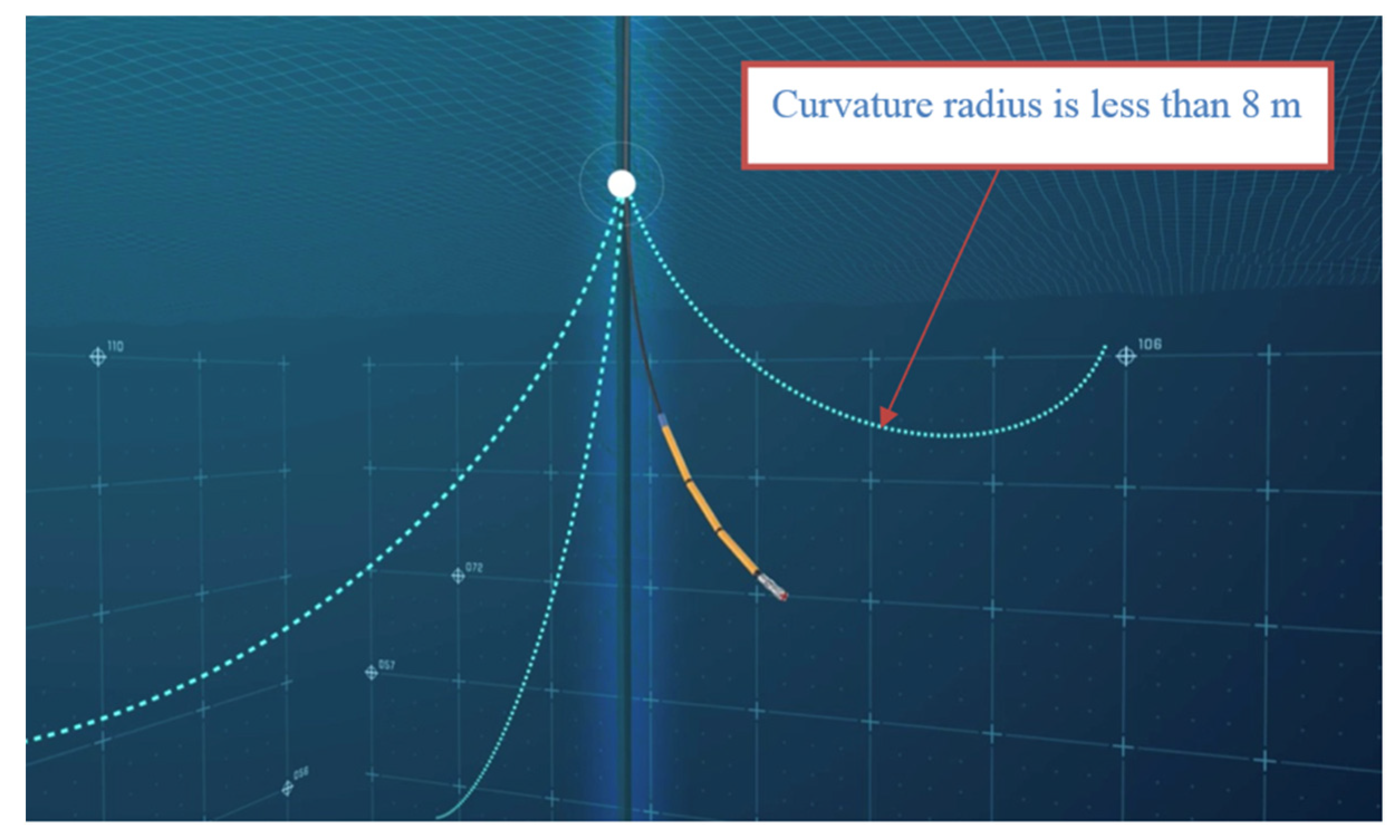
- The intensity of the increase in curvature is not more than 3 degree per 10 m.
- In the operating interval, it is necessary to have a cement ring of satisfactory quality behind the production string.
- There should be no casing centralizers in the channel drilling interval.
- The frequency of holes in the previously made perforation is not more than 60 holes per a linear meter.
- The temperature at the bottom of the well is not more than 150 °C.
- The productive formation thickness is more than 3 m.
2. Materials and Methods
2.1. Formulation of the Problem
2.2. Calculation of Geometric Parameters of Alternative PS Variants
- (1)
- Determination of the contour diameter and the eccentricity of the catching;
- (2)
- Determination of the cross-sectional area;
- (3)
- Determination of the helical surface pitch;
- (4)
- Determination of the number of contact lines and the turn-to-turn pressure drop for the selected number of steps (it is assumed to be k = 1.5);
- (5)
- Determination of the length of the elastic stator line (active length of the PS).
2.3. Calculation of Operational Parameters of Alternative PS Variants
3. Results
3.1. Results of the Geometric Parameters Calculation of Alternative PS Variants
3.2. Results of the Operational Parameters Calculation of Alternative PS Variants
4. Discussion
5. Conclusions
Author Contributions
Funding
Institutional Review Board Statement
Informed Consent Statement
Data Availability Statement
Conflicts of Interest
References
- Vasilenko, I.R.; Chertenkov, M.V.; Shepel, K.Y. Bench tests of the models of well casing during the perforation by cumulative perforators. Neftyanoe Khozyaystvo Oil Ind. 2015, 2, 32–36. [Google Scholar]
- Vzryvgeoservice. Available online: https://www.vzgs.ru/en/ (accessed on 21 May 2021).
- Nekko. Available online: http://en.nekko.ru/servisi/perforaciya (accessed on 21 May 2021).
- Chernyshov, S.E.; Repina, V.A.; Krysin, N.I.; Macdonald, D.I.M. Improving the efficiency of terrigenous oil-saturated reservoir development by the system of oriented selective slotted channels. J. Min. Inst. 2021, 246, 660–666. [Google Scholar] [CrossRef]
- Navarro, J.B. Slotted-liner completions used in the first horizontal wells in Mexico. In Proceedings of the International Conference on Horizontal Well Technology Calgary, Alberta , AL, Canada, 18–20 November 1996; pp. 613–618. [Google Scholar]
- Krezol. Available online: https://www.krezol.ru/oilservice/intensifikatsiya-pritoka/ (accessed on 21 May 2021).
- Radial Drilling Services. Available online: /https://radialdrilling.com/ (accessed on 21 May 2021).
- Yan, J.; Cui, M.-Y.; Jiang, W.-D.; He, A.-L.; Liang, C.; Zhang, H.-W. Research of Hydraulic Jet Radial Drilling and Its Application in Carbonate Reservoir. Well Test. 2017, 26, 69–72. [Google Scholar]
- Han, Y.; Zhu, S.-G.; Wang, F.-S.; Liang, F.-M.; Li, H.-C.; Li, Q.-Z.; Wu, K.; Wang, L. Deep penetrating horizontal drilling techniques status quo analysis. In Proceedings of the International Field Exploration and Development Conference 2019. IFEDC 2019; Springer Series in Geomechanics and Geoengineering; Springer: Berlin/Heidelberg, Germany, 2020; pp. 1499–1507. [Google Scholar] [CrossRef]
- Medetbekova, M.K.; Christensen, H.F.; Salimzadeh, S.; Bakker, R.R.; Nick, H.M. Experimental Investigation of Drilling Lateral Boreholes in Chalk Rocks with High-Pressure Jets. Int. J. Geomech. 2020, 20. [Google Scholar] [CrossRef]
- PetroJet. Available online: http://www.icota-canada.com/Resources/Documents/ICoTA%202011%20Roundtable%20Presentations/Advanced-Fluid-Jet-Systems.pdf (accessed on 21 May 2021).
- ViperDrill. Available online: http://www.viperdrill.com/ (accessed on 21 May 2021).
- Fishboned. Available online: https://www.fishbones.as/ (accessed on 21 May 2021).
- Maslin, E. Gone fishing. Offshore Eng. 2015, 40, 40–41. [Google Scholar]
- Mansourizadeh, M.; Jamshidian, M.; Bazargan, P.; Mohammadzadeh, O. Wellbore stability analysis and breakout pressure prediction in vertical and deviated boreholes using failure criteria–A case study. J. Pet. Sci. Eng. 2016, 145, 482–492. [Google Scholar] [CrossRef]
- Lyagov, A.V. Dynamic Arrangements for Downhole Drilling. Ph.D. Thesis, Ufa State Oil Technical University, Ufa, Russia, 2005. [Google Scholar]
- Lyagov, I.A. Substantiation and Development of A Technology For Secondary Penetration of Productive Formations By Branched Wells of Ultra-Small Diameter. Ph.D. Thesis, Saint Petersburg Mining University, Saint Petersburg, Russia, 2014. [Google Scholar]
- Lyagov, A.V.; Lyagov, I.A.; Suleymanov, I.N. Anti-vibration—stabilizing drill bottomhole assembly for «Perfobore» technical system. Socar Proc. 2021, 14, 24–32. [Google Scholar] [CrossRef]
- Lyagov, A.V.; Lyagov, I.A. Selection of permissible radii of curvature of ultra-small diameter wells (channels) for the Perfobur technical system. Expo. Oil Gas. 2014, 6, 47–52. [Google Scholar]
- Lyagov, I.A. Analysis of the results of field tests of the technical system «Perfobur». Analytical synthesis of basic units of «Perfobur» with increased reliability for drilling extra-long channels along the predicted trajectory. Pet. Eng. 2014, 1, 52–76. [Google Scholar]
- Lyagov, I.A.; Baldenko, F.D.; Lyagov, A.V.; Yamaliev, V.U.; Lyagova, A.A. Methodology for calculating technical efficiency of power sections in small-sized screw downhole motors for the «Perfobur» system. J. Min. Inst. 2019, 240, 694–700. [Google Scholar] [CrossRef]
- Dvoynikov, M.; Kunshin, A.; Blinov, P.; Morozov, V. Development of mathematical model for controlling drilling parameters with screw downhole motor. Int. J. Eng. Trans. A Basics 2020, 33, 1423–1430. [Google Scholar] [CrossRef]
- Dvoynikov, M.; Syzrantsev, V.; Syzrantseva, K. Designing a high resistant, high-torque downhole drilling motor. Int. J. Eng. Trans. A: Basics 2017, 30, 1615–1621. [Google Scholar] [CrossRef]
- Baldenko, D.F.; Gnoevykh, A.N. One-Screw Hydraulic Machines in the Oil Industry; IRC Gazprom: Moscow, Russia, 2007; Volume 2. [Google Scholar]


| Initial Data | Units | Value |
|---|---|---|
| Body diameter, Db | mm | 43–55 |
| Maximum length of working bodies (taking thread and hinge placements into account), Lmax | mm | 650 |
| Flow rate, Q | L/s | 1–2 |
| Rotational speed, n | RPM | 100–150 |
| Motor torque | N·m | 150 |
| Motor torque of one engine section, M | N·m | 75 |
| Pressure drop of one engine section, P | MPa | 4 |
| Body Diameter, Db,mm | 43 | 45 | 48 | 55 | |
|---|---|---|---|---|---|
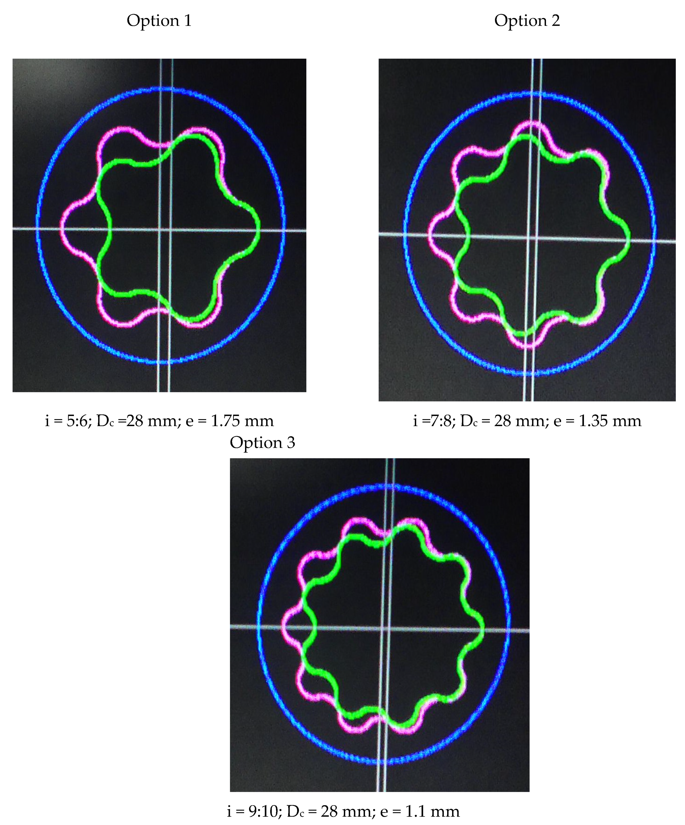
| 1 | Contour diameter, Dc, mm | 28 | 30 | 33 | 37 |
| 2 | Eccentricity, mm | ||||
| e 5:6 | 1.75 | 1.85 | 2.05 | 2.3 | |
| e 7:8 | 1.35 | 1.45 | 1.6 | 1.8 | |
| e 9:10 | 1.1 | 1.2 | 1.3 | 1.5 | |
| 3 | Cross-sectional area, cm2 | ||||
| s 5:6 | 1.25 | 1.42 | 1.73 | 1.92 | |
| s 7:8 | 1.02 | 1.17 | 1.42 | 1.57 | |
| s 9:10 | 0.85 | 0.99 | 1.19 | 1.34 | |
| 4 | Stage of stator, mm | ||||
| Tst 5:6 | 378 | 330 | 273 | 307 | |
| Tst 7:8 | 320 | 284 | 236 | 265 | |
| Tst 9:10 | 300 | 260 | 220 | 248 | |
| 5 | Average diameter of the rotor, mm | ||||
| dav 5:6 | 21.0 | 22.6 | 24.8 | 27.9 | |
| dav 7:8 | 22.6 | 24.2 | 26.6 | 29.9 | |
| dav 9:10 | 23.6 | 25.2 | 27.8 | 31.2 | |
| 6 | Surface shape coefficient | ||||
| cs 5:6 | 15.0 | 12.2 | 9.2 | 10.35 | |
| cs 7:8 | 12.4 | 10.3 | 7.8 | 8.7 | |
| cs 9:10 | 11.4 | 9.3 | 7.1 | 7.98 | |
| 7 | Length of the stator line PS, mm | ||||
| L 5:6 | 567 | 495 | 410 | 462 | |
| L 7:8 | 480 | 426 | 354 | 398 | |
| L 9:10 | 450 | 390 | 330 | 371 | |
| 8 | Number of contact lines | ||||
| λ 5:6 | 4 | ||||
| λ 7:8 | 5 | ||||
| λ 9:10 | 6 | ||||
| № | Parameters | Variant of the PS | |||
|---|---|---|---|---|---|
| 5:6 | 7:8 | 9:10 | |||
| 1 | Eccentricity, mm | e | 1.75 | 1.35 | 1.1 |
| 2 | Eccentricity factor | c0 | 1.175 | 1.175 | 1.175 |
| 3 | Tooth shape coefficient | ce | 2.175 | 2.175 | 2.175 |
| 4 | Offset coefficient | ξ | −1.050 | −1.030 | −1.023 |
| 5 | Surface shape coefficient | cs | 15.0 | 12.4 | 11.4 |
| 6 | Helical line rise angle, grad | Θ | 78.2 | 75.8 | 74.6 |
| 7 | Average diameter of the rotor, mm | dav | 21.0 | 22.6 | 23.6 |
| 8 | Root diameter of the rotor profile, mm | dr | 17.5 | 20.2 | 21.4 |
| 9 | Stage of rotor, mm | Tr | 315 | 280 | 270 |
| 10 | Stage of stator, mm | Tst | 378 | 320 | 300 |
| 11 | Stator cover length, mm | L | 567 | 480 | 450 |
| 12 | Area of flow section, cm2 | S | 1.25 | 1.02 | 0.85 |
| 13 | Wet perimeter, mm | π | 17.0 | 17.9 | 18.4 |
| 14 | Area of contact line, cm2 | Sκ | 4.1 | 4.5 | 4.8 |
| 15 | Hydraulic radius, mm | Rh | 7.4 | 5.7 | 4.6 |
| 16 | Actual displacement volume, L | V | 0.236 | 0.227 | 0.230 |
| 17 | Length of contact line, m | Lc | 298 | 351 | 423 |
| 18 | Number of contact lines | Λ | 4 | 5 | 6 |
| 19 | Inter-turn pressure drop, MPa | Pc | 1.0 | 0.8 | 0.67 |
| 20 | Coefficient of unevenness of the diametrical dimensions of the profile | kd | 0.33 | 0.24 | 0.19 |
| 21 | Rotary mass (length L), kg | m | 1.5 | 1.5 | 1.5 |
| 22 | Output speed, RPM | n | 203 | 211 | 209 |
| 23 | Radial hydraulic force, kN | Fh | 7.1 | 6.9 | 6.8 |
| 24 | Inertial force, kN | Fin | 0.03 | 0.05 | 0.07 |
| 25 | Skewing moment, N·m | Msc | 665 | 565 | 550 |
| 26 | Axial force, kN | Fax | 4.1 | 4.6 | 5.0 |
| 27 | Loading frequency of the stator lining, Hz | F | 16.9 | 24.6 | 31.4 |
| 28 | Sliding speed, m/s | vsl | 0.45 | 0.49 | 0.50 |
| 29 | Axial velocity of the fluid, m/s | w | 6.40 | 7.88 | 9.38 |
| 30 | Parameter of the curvature of the profile | ρpr/e | 0.72 | 0.72 | 0.72 |
| 31 | Hydraulic losses, MPa | Ph | 0.009 | 0.014 | 0.024 |
| 32 | Minimum contact stress, MPa | K | 2.24 | 1.31 | 0.78 |
| Kinematic Ratio | |||
|---|---|---|---|
| 5:6 | 7:8 | 9:10 | |
| ftr (i), mm/mm | 31.4 | 25.2 | 24.0 |
| Technical Indicator | Variant of the PS | |
|---|---|---|
| 7:8 | 9:10 | |
| Geometric indicator | - | Preferable to eccentricity, axial dimension, the number of contact lines, turn-to-turn pressure drop and the coefficient of irregularity of diametrical dimensions profile. |
| Hydraulic indicator | Preferable to axial fluid velocity and hydraulic losses. 1 | |
| Tribological indicator | Preferable to the loading frequency of the stator line. | Preferable to length of contact lines, sliding speed, contact stress. |
| Power indicator | Preferable to in terms of inertial force. | |
| Axial force in PS; radial hydraulic force and skewing moment both pairs under consideration are at approximately the same level. 2 | ||
Publisher’s Note: MDPI stays neutral with regard to jurisdictional claims in published maps and institutional affiliations. |
© 2021 by the authors. Licensee MDPI, Basel, Switzerland. This article is an open access article distributed under the terms and conditions of the Creative Commons Attribution (CC BY) license (https://creativecommons.org/licenses/by/4.0/).
Share and Cite
Liagov, I.; Liagov, A.; Liagova, A. Optimization of the Configuration of the Power Sections of Special Small-Sized Positive Displacement Motors for Deep-Penetrating Perforation Using the Technical System “Perfobore”. Appl. Sci. 2021, 11, 4977. https://doi.org/10.3390/app11114977
Liagov I, Liagov A, Liagova A. Optimization of the Configuration of the Power Sections of Special Small-Sized Positive Displacement Motors for Deep-Penetrating Perforation Using the Technical System “Perfobore”. Applied Sciences. 2021; 11(11):4977. https://doi.org/10.3390/app11114977
Chicago/Turabian StyleLiagov, Ilia, Alexander Liagov, and Anastasiia Liagova. 2021. "Optimization of the Configuration of the Power Sections of Special Small-Sized Positive Displacement Motors for Deep-Penetrating Perforation Using the Technical System “Perfobore”" Applied Sciences 11, no. 11: 4977. https://doi.org/10.3390/app11114977
APA StyleLiagov, I., Liagov, A., & Liagova, A. (2021). Optimization of the Configuration of the Power Sections of Special Small-Sized Positive Displacement Motors for Deep-Penetrating Perforation Using the Technical System “Perfobore”. Applied Sciences, 11(11), 4977. https://doi.org/10.3390/app11114977