
Electromagnetic Field Analysis and Design of a Hermetic Interior Permanent Magnet Synchronous Motor with Helical-Grooved Self-Cooling Case for Unmanned Aerial Vehicles


Abstract
:1. Introduction
2. Fluid Flow Analysis Governing Equations
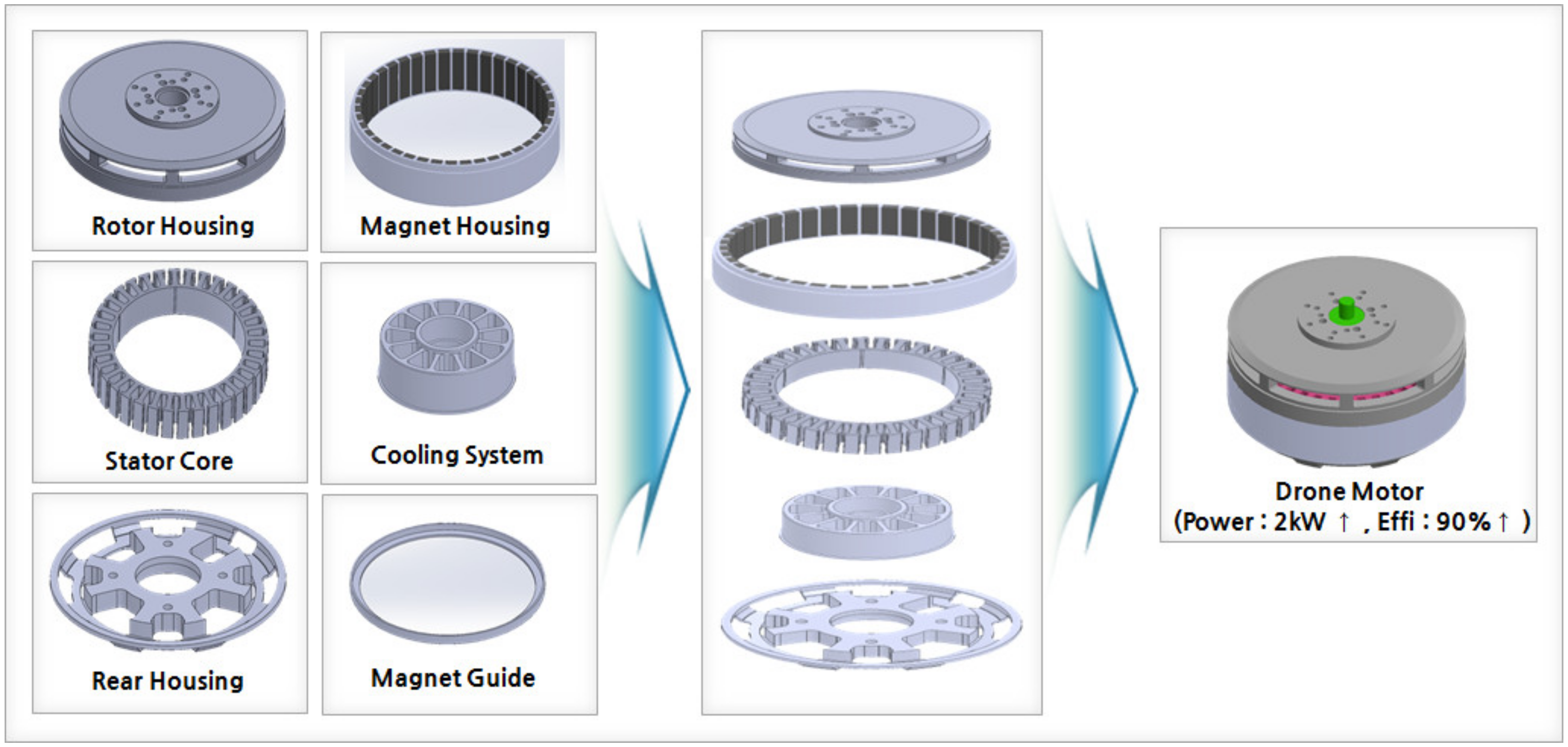
3. Design and Electromagnetic Field Analysis of IPM Synchronous Motor
3.1. Stator Analysis Model Specification
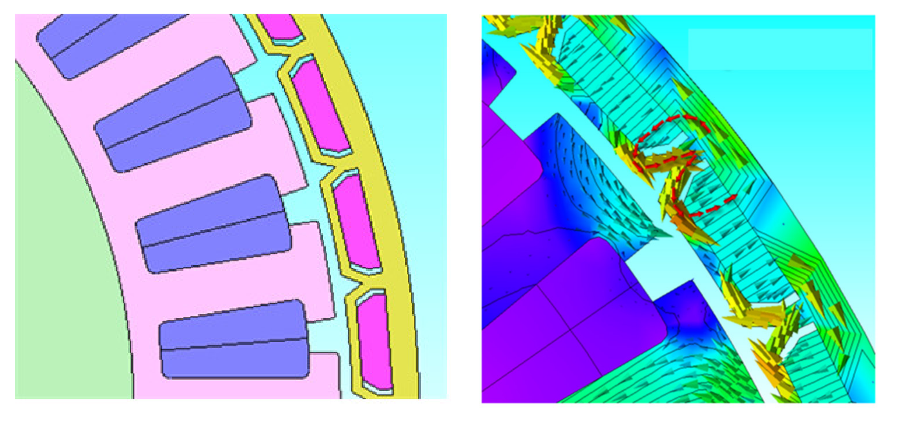
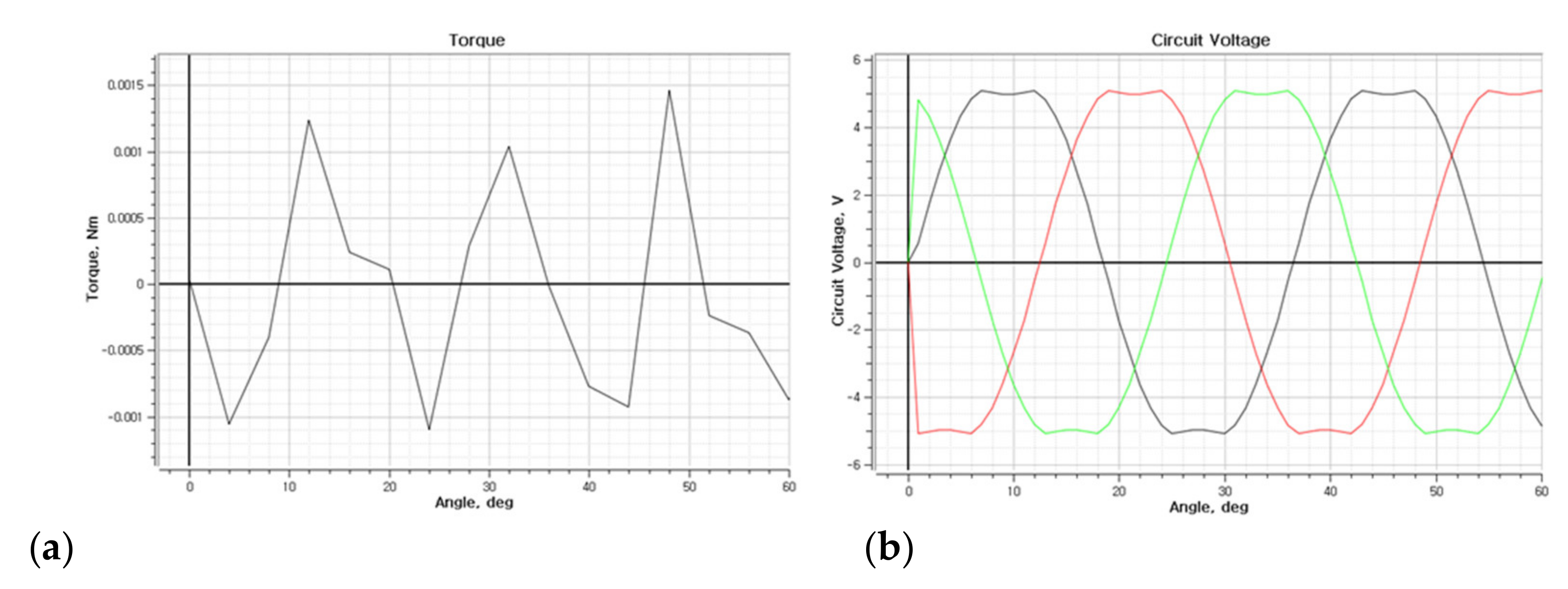
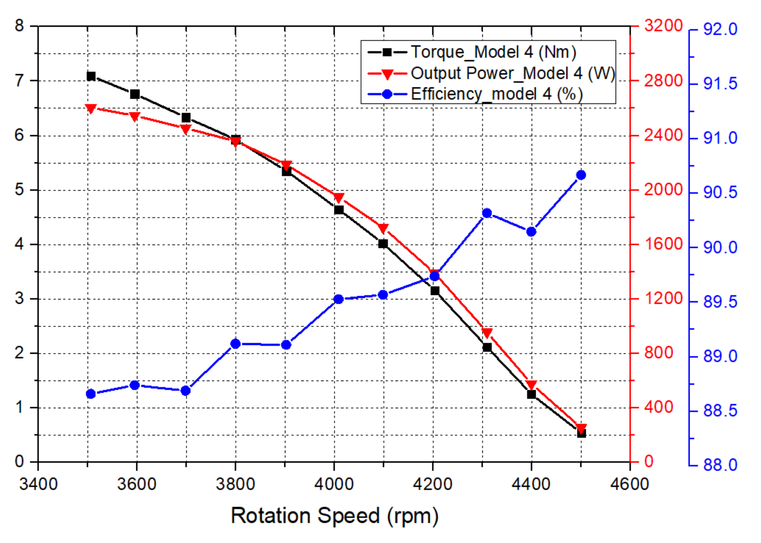
3.2. Electromagnetic Field Analysis and Results
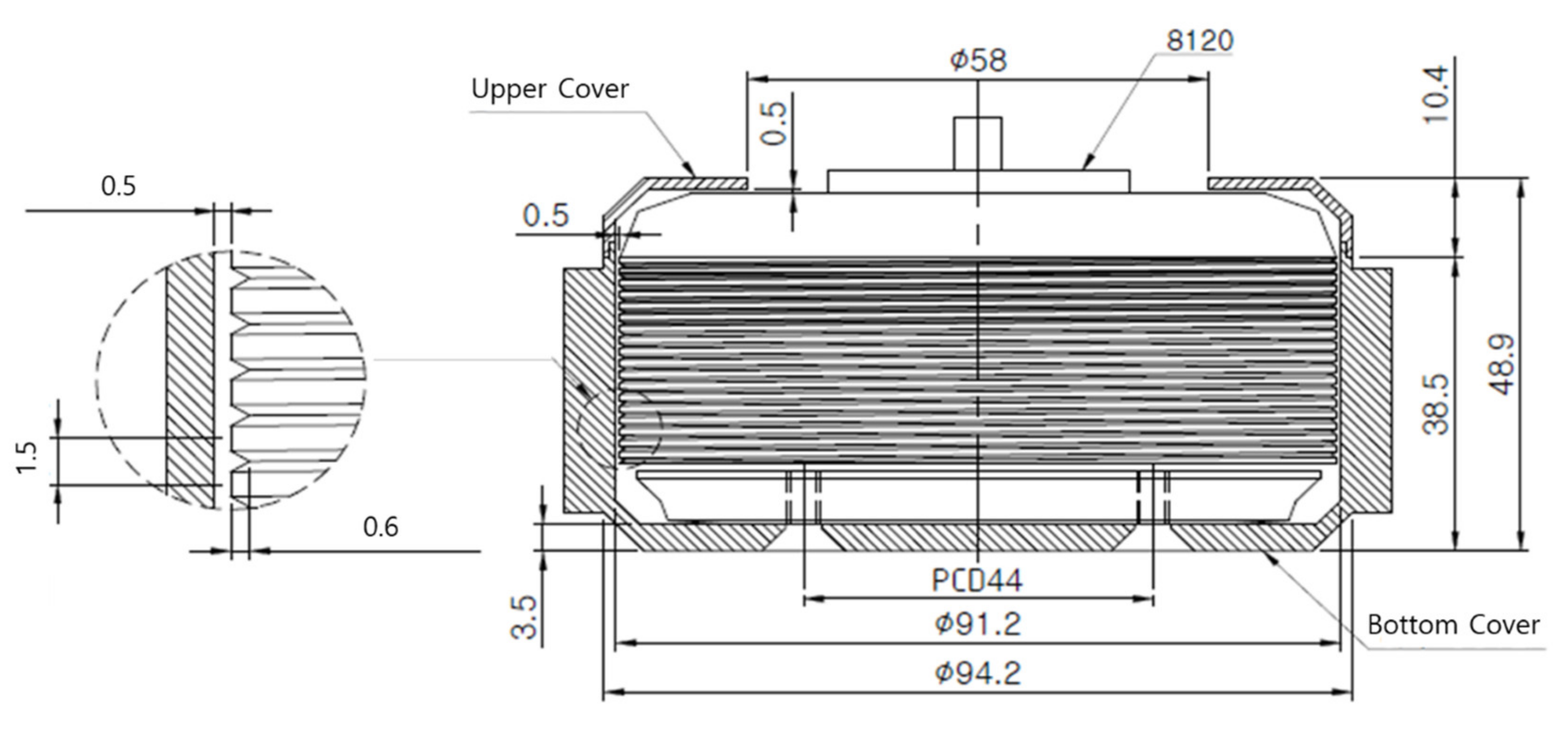
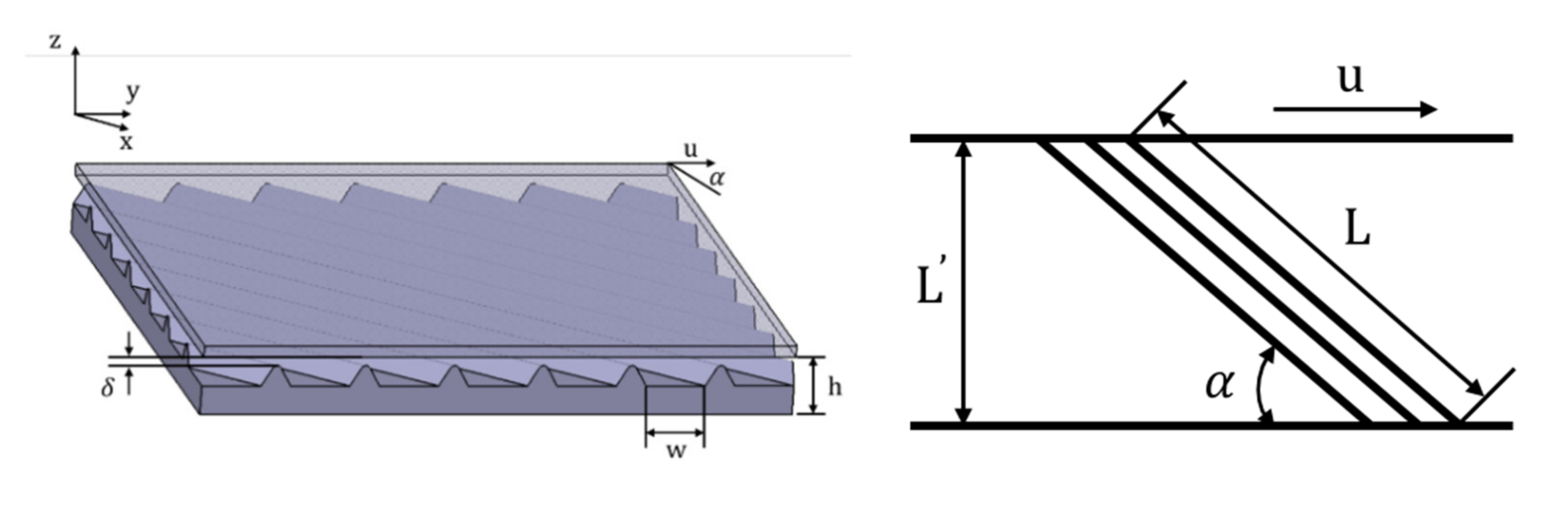
4. Design of the Helical-Grooved Self-Cooling Case
5. Environment and Results of the Experiment on Heat Dissipation Characteristics
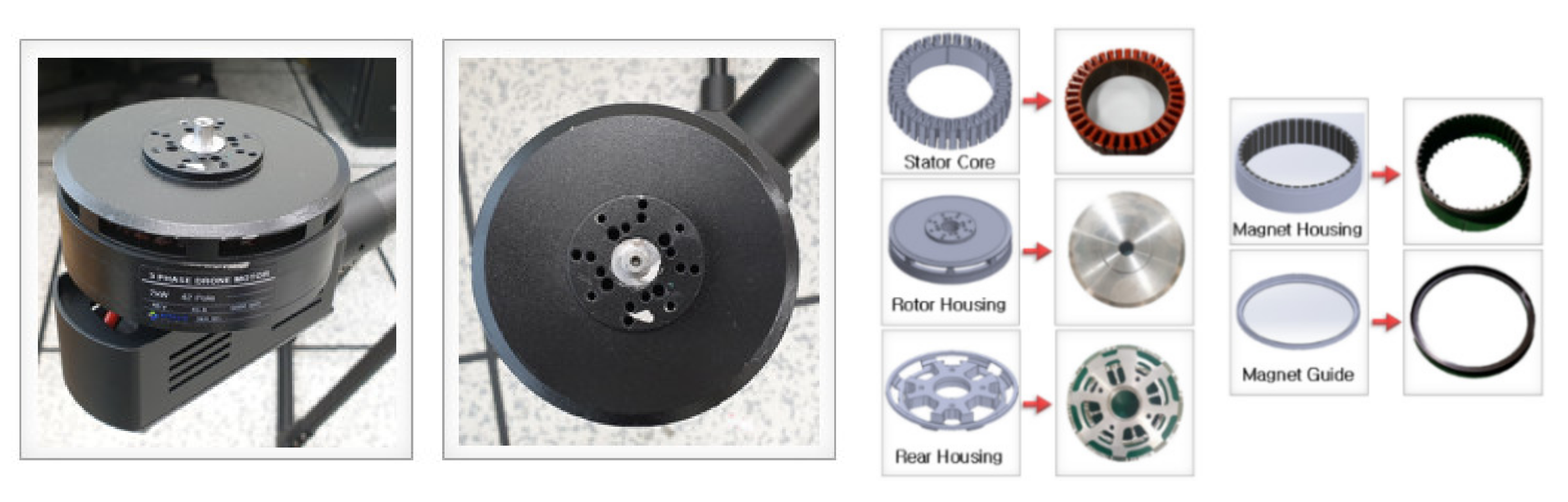
5.1. Prototyping
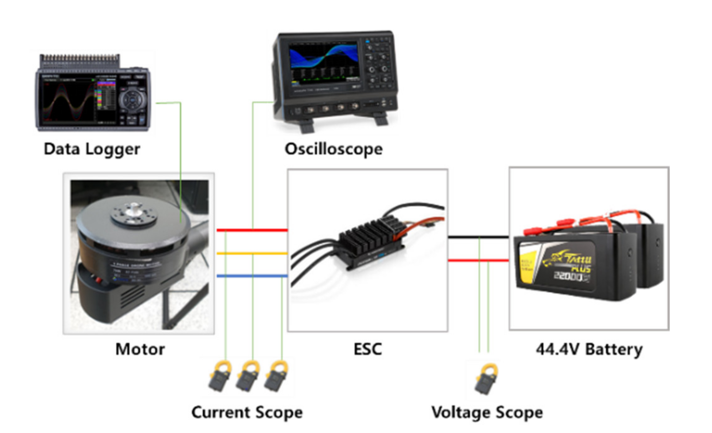
5.2. Configuration of the Heat Dissipation Characteristics Experimental Environment
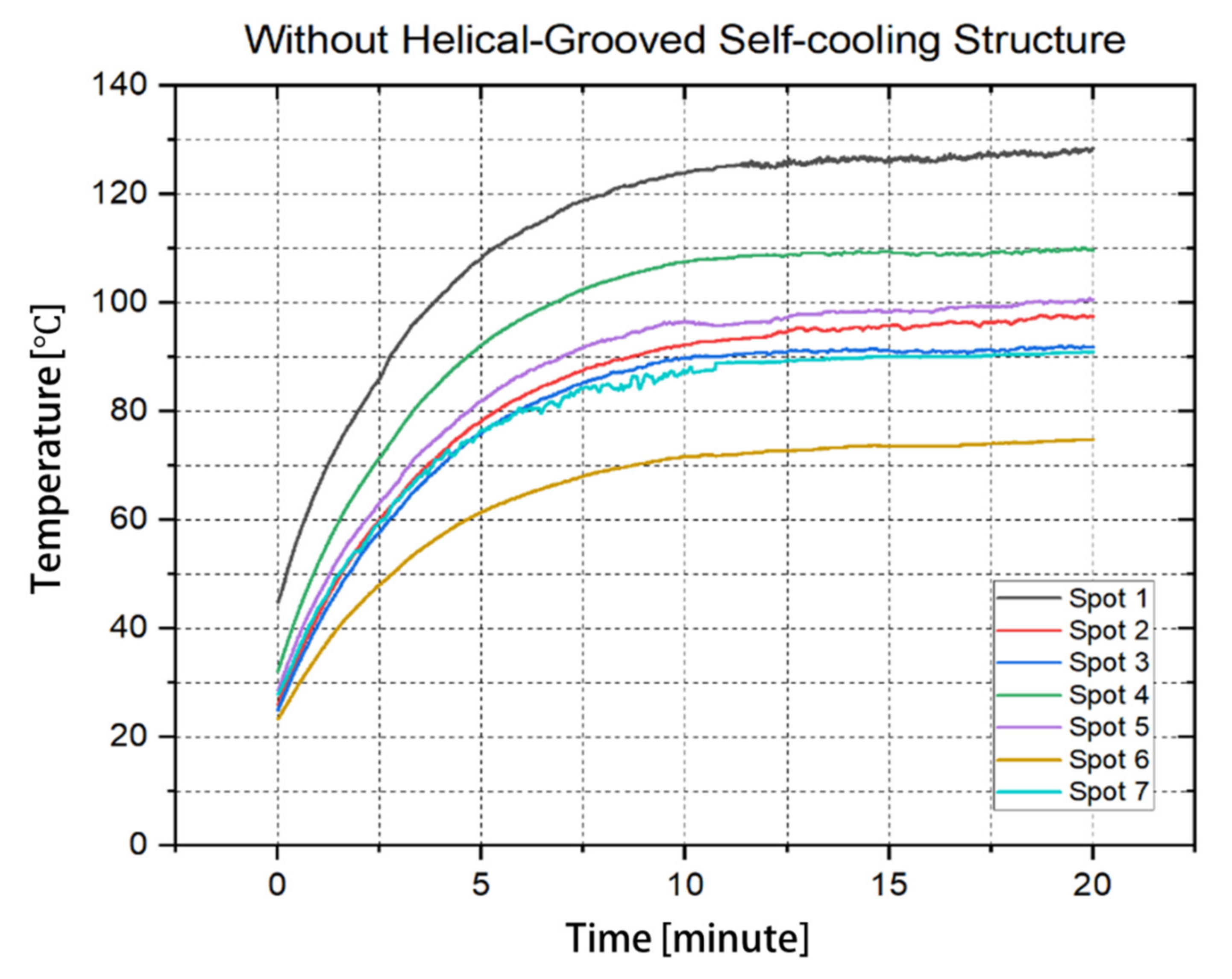
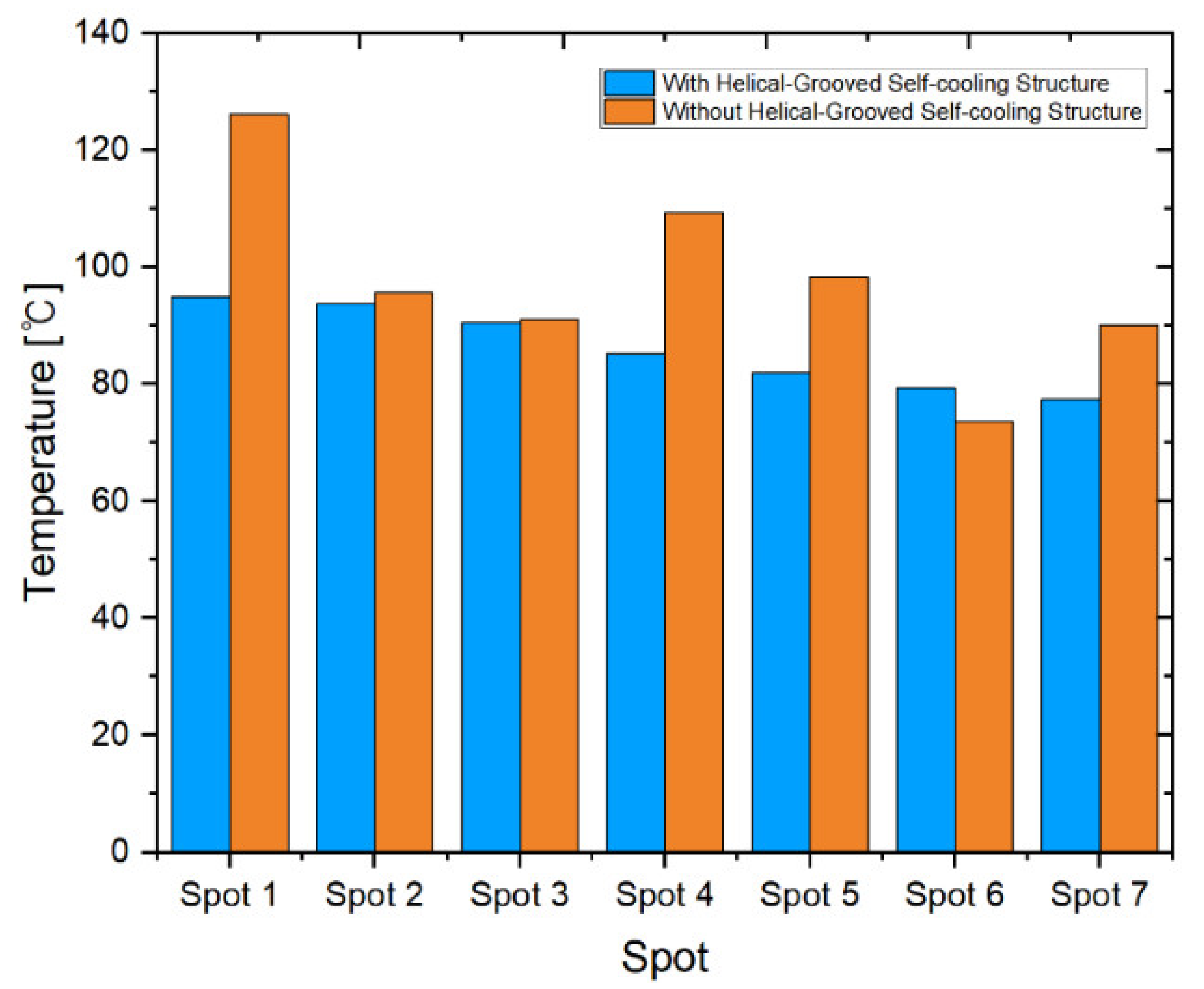
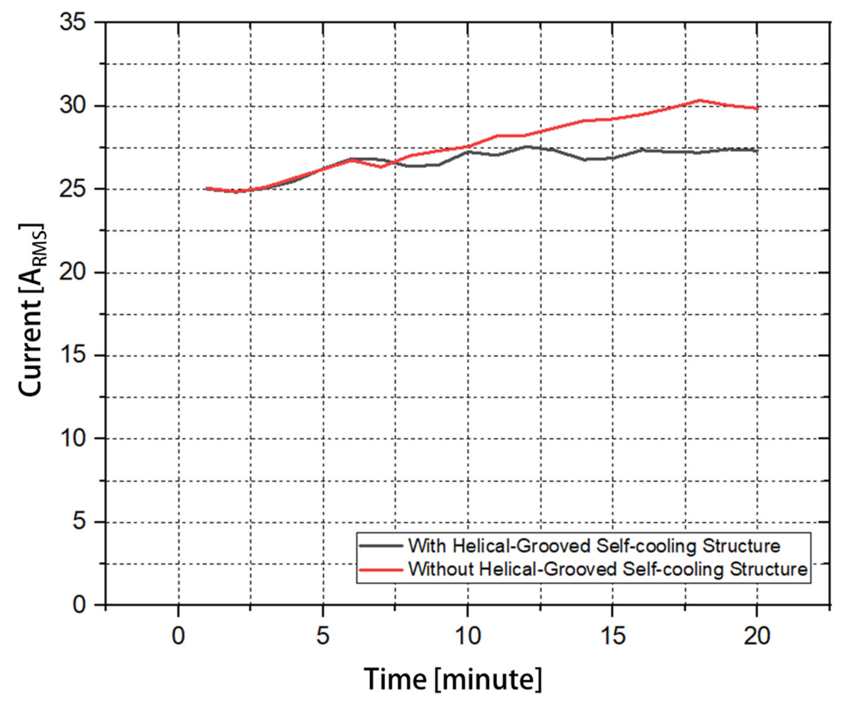
5.3. Heat Dissipation Characteristics: Experimental Results and Comparison
6. Conclusions
Author Contributions
Funding
Institutional Review Board Statement
Informed Consent Statement
Conflicts of Interest
References
- Xu, X.; Deng, Y. UAV Power Component—DC Brushless Motor Design with Merging Adjacent-Disturbances and Integrated-Dispatching Pigeon-Inspired Optimization. IEEE Trans. Magn. 2018, 54, 1–7. [Google Scholar] [CrossRef]
- Gong, A.; MacNeill, R.; Verstraete, D. Performance testing and modeling of a brushless dc motor, electronic speed controller and propeller for a small uav application. In Proceedings of the 2018 Joint Propulsion Conference, Cincinnati, OH, USA, 9–11 July 2018; p. 4584. [Google Scholar]
- Magsino, E.R.; Say, M.F.; Tan, J.A. Achieving Complete UAV Delivery in the Presence of Motor Failures. In Proceedings of the IEEE 10th Symposium on Computer Applications & Industrial Electronics (ISCAIE), Penang, Malaysia, 18–19 April 2020; pp. 1–5. [Google Scholar]
- Lee, K.H.; Cha, H.R.; Kim, Y.B. Development of an interior permanent magnet motor through rotor cooling for electric vehicles. Appl. Therm. Eng. 2016, 95, 348–356. [Google Scholar] [CrossRef]
- Cho, S.K.; Jung, K.H.; Choi, J.Y. Design optimization of interior permanent magnet synchronous motor for electric compressors of air-conditioning systems mounted on EVs and HEVs. IEEE Trans. Magn. 2018, 54, 1–5. [Google Scholar] [CrossRef]
- Zhao, N.; Schofield, N.; Hu, Y. Phase voltage distortion of IPM and SPM machines with distributed windings in field weakening region. J. Eng. 2019, 3872–3877. [Google Scholar] [CrossRef]
- Fang, G.; Yuan, W.; Yan, Z.; Sun, Y.; Tang, Y. Thermal management integrated with three-dimensional heat pipes for air-cooled permanent magnet synchronous motor. Appl. Therm. Eng. 2019, 152, 594–604. [Google Scholar] [CrossRef]
- Cuiping, L.I.; Zhengwei, G.U.A.N.; Junhui, L.I.; Bing, Z.; Xiucui, D.I.N.G. Optimal design of cooling system for water cooling motor used for mini electric vehicle. In Proceedings of the 20th International Conference on Electrical Machines and Systems (ICEMS), Sydney, NSW, Australia, 11–14 August 2017; pp. 1–4. [Google Scholar]
- Guo, F.; Zhang, C. Oil-cooling method of the permanent magnet synchronous motor for electric vehicle. Energies 2019, 12, 2984. [Google Scholar] [CrossRef] [Green Version]
- Ponomarev, P.; Polikarpova, M.; Pyrhönen, J. Conjugated fluid-solid heat transfer modeling of a directly-oil-cooled PMSM using CFD. In Proceedings of the International Symposium on Power Electronics Power Electronics, Electrical Drives, Automation and Motion, Sorrento, Italy, 20–22 June 2012; pp. 141–145. [Google Scholar]
- Davin, T.; Pellé, J.; Harmand, S.; Yu, R. Experimental study of oil cooling systems for electric motors. Appl. Therm. Eng. 2015, 75, 1–13. [Google Scholar] [CrossRef]
- Nategh, S.; Huang, Z.; Krings, A.; Wallmark, O.; Leksell, M. Thermal modeling of directly cooled electric machines using lumped parameter and limited CFD analysis. IEEE Trans. Energy Convers. 2013, 28, 979–990. [Google Scholar] [CrossRef]
- Lim, D.H.; Kim, S.C. Thermal performance of oil spray cooling system for in-wheel motor in electric vehicles. Appl. Therm. Eng. 2014, 63, 577–587. [Google Scholar] [CrossRef]
- Park, J.M.; Kim, K.Y.; Heo, M.W. Comparative Performance Analysis of an Electric Motor Cooling Fan with Various Inlet Vent and Blade Shapes. Int. J. Fluid Mach. Syst. 2017, 10, 394–403. [Google Scholar] [CrossRef]
- Gai, Y.; Kimiabeigi, M.; Widmer, J.D.; Chong, Y.C.; Goss, J.; SanAndres, U.; Staton, D.A. Shaft cooling and the influence on the electromagnetic performance of traction motors. In Proceedings of the 2017 IEEE International Electric Machines and Drives Conference (IEMDC), Miami, FL, USA, 21–24 May 2017; pp. 1–6. [Google Scholar]
- Ai, M.; Yang, Y.; Xu, Y.; Li, Z.; Xu, L.; Wang, W. Research on Thermal Characteristics of Internal Ventilated Paths in Compact Medium High-Voltage Motor Based Fluid Network Decoupling. IEEE Access 2019, 7, 79268–79276. [Google Scholar] [CrossRef]
- Tiwari, A.; Yavuzkurt, S. URANS Modeling of Effects of Rotation on Flow Distribution and Heat Transfer in an Electric Motor. In ASME International Mechanical Engineering Congress and Exposition; American Society of Mechanical Engineers: New York, NY, USA, 2020; Volume 84584, p. V010T10A026. [Google Scholar]
- Kusuma, H.R.; Purwadi, A. Thermal modelling and analysis of 75 kW permanent magnet synchronous motor for medium bus application based on JMAG. In Proceedings of the 2017 4th International Conference on Electric Vehicular Technology (ICEVT), Bali, Indonesia, 2–5 October 2017; pp. 30–35. [Google Scholar]
- Kang, G.H.; Hong, J.P.; Kim, G.T.; Park, J.W. Improved parameter modeling of interior permanent magnet synchronous motor based on finite element analysis. IEEE Trans. Magn. 2000, 36, 1867–1870. [Google Scholar] [CrossRef]
- Venna, K.R.; Urbanek, H.; Anger, N. Difference between switching of motors and generators with vacuum technology. Cired-Open Access Proc. J. 2017, 1, 124–127. [Google Scholar] [CrossRef] [Green Version]


| Winding Diagram | Parameters | Unit | Value |
|---|---|---|---|
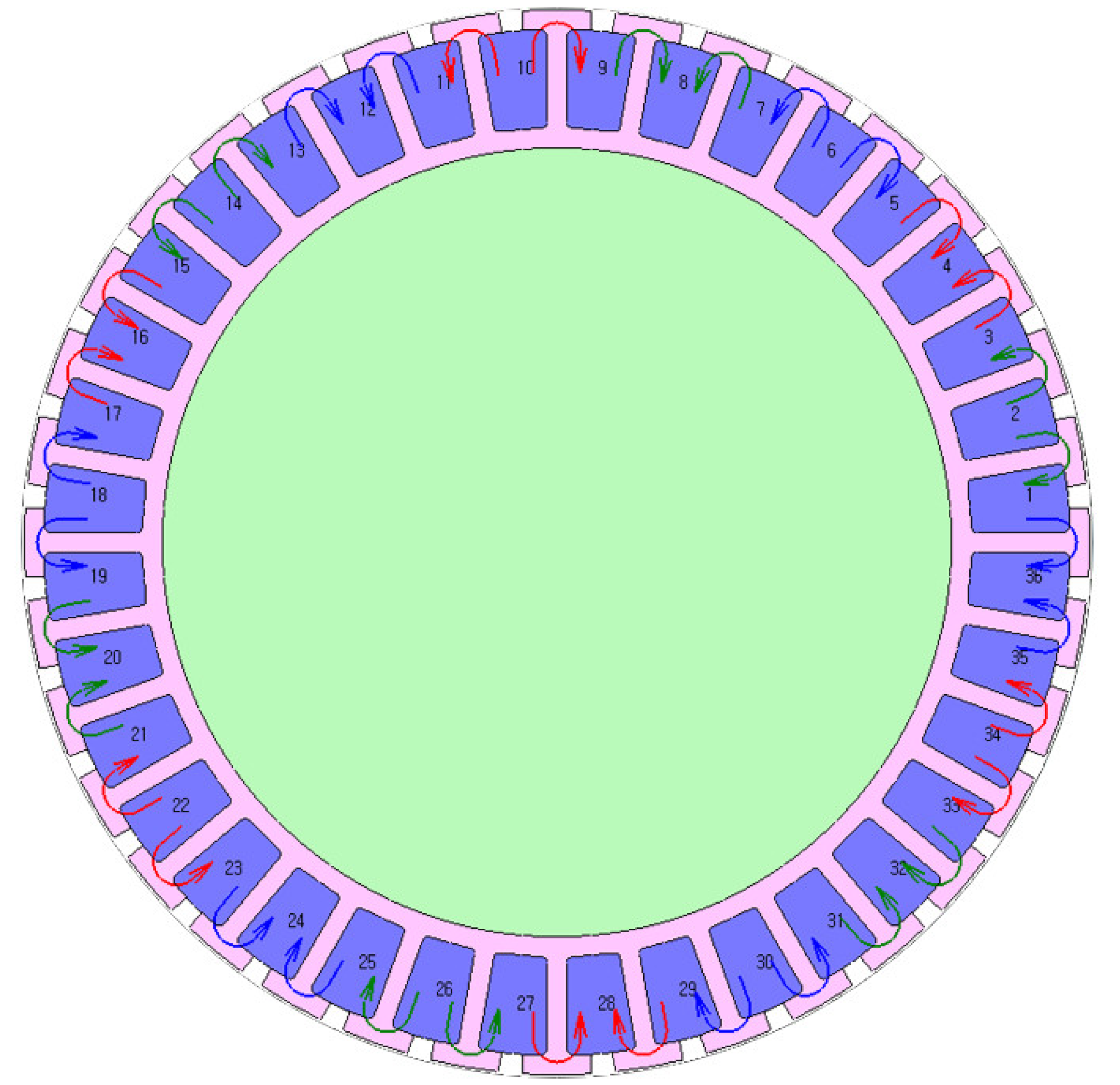 | Number of Slot | Slot | 36 |
| Number of Pole | Pole | 42 | |
| Outside Diameter | mm | 81 | |
| Inside Diameter | mm | 60 | |
| Stack Length | mm | 20 | |
| Air Gap | mm | 0.4 | |
| Number of Turns | Turns | 10 | |
| Number of Strands | Turns | 6 | |
| Phase Resistance | mΩ | 0.202 | |
| Slot Fill Factor | % | 43.69 | |
| Rated Mechanical Power | W | 2000 | |
| Rated Rotational Frequency | Hz | 60 |
| Parameter | Unit | Value | |
|---|---|---|---|
| Helix angle | 10 | ||
| Channel width | mm | 1.5 | |
| Channel depth | mm | 0.6 | |
| Clearance | mm | 0.5 | |
| Part | Material |
|---|---|
| Rotor Housing and Rear Housing and Cooling Case | Magnesium Alloy (Mg + 4 wt.%Zn + 1 wt.%Y) |
| Magnet Housing | SKD11 |
| Stator Core | 35PN210 |
| Coil | Copper |
| Permanent Magnet | N45SH |
| Thermocouple Wire | Location |
|---|---|
| Spot 1 | Coil |
| Spot 2 | Top of Stator inside |
| Spot 3 | Bottom of Stator inside |
| Spot 4 | Top of Stator outside |
| Spot 5 | Bottom of Stator Outside |
| Spot 6 | Inner Bottom Cover |
| Spot 7 | Outer Bottom Cover |
Publisher’s Note: MDPI stays neutral with regard to jurisdictional claims in published maps and institutional affiliations. |
© 2021 by the authors. Licensee MDPI, Basel, Switzerland. This article is an open access article distributed under the terms and conditions of the Creative Commons Attribution (CC BY) license (https://creativecommons.org/licenses/by/4.0/).
Share and Cite
Lee, H.-S.; Hwang, M.-H.; Cha, H.-R. Electromagnetic Field Analysis and Design of a Hermetic Interior Permanent Magnet Synchronous Motor with Helical-Grooved Self-Cooling Case for Unmanned Aerial Vehicles. Appl. Sci. 2021, 11, 4856. https://doi.org/10.3390/app11114856
Lee H-S, Hwang M-H, Cha H-R. Electromagnetic Field Analysis and Design of a Hermetic Interior Permanent Magnet Synchronous Motor with Helical-Grooved Self-Cooling Case for Unmanned Aerial Vehicles. Applied Sciences. 2021; 11(11):4856. https://doi.org/10.3390/app11114856
Chicago/Turabian StyleLee, Hae-Sol, Myeong-Hwan Hwang, and Hyun-Rok Cha. 2021. "Electromagnetic Field Analysis and Design of a Hermetic Interior Permanent Magnet Synchronous Motor with Helical-Grooved Self-Cooling Case for Unmanned Aerial Vehicles" Applied Sciences 11, no. 11: 4856. https://doi.org/10.3390/app11114856
APA StyleLee, H.-S., Hwang, M.-H., & Cha, H.-R. (2021). Electromagnetic Field Analysis and Design of a Hermetic Interior Permanent Magnet Synchronous Motor with Helical-Grooved Self-Cooling Case for Unmanned Aerial Vehicles. Applied Sciences, 11(11), 4856. https://doi.org/10.3390/app11114856