Article

Transformative Use of Additive Technology in Design and Manufacture of Hydraulic Actuator for Fly-by-Wire System

1
Domin, ul. Wojska Polskiego 20, 39-300 Mielec, Poland
2
Faculty of Mechanical Engineering and Aeronautics, Rzeszow University of Technology, al. Powstańców Warszawy 8, 35-959 Rzeszów, Poland
*
Authors to whom correspondence should be addressed.
Appl. Sci. 2021, 11(11), 4772; https://doi.org/10.3390/app11114772
Submission received: 23 April 2021 / Revised: 15 May 2021 / Accepted: 18 May 2021 / Published: 22 May 2021
(This article belongs to the Section Mechanical Engineering)

Abstract

:
In this paper, the results of research on additively manufactured aerospace parts made of maraging steel are presented. This state-of-the-art technology seems to have the highest potential for practical use in the field of ultra-light and high-performance aerospace hydraulic parts. The strength properties of representative specimens made with steel 1.2709 were investigated. The researchers conducted static tensile testing, fatigue tensile testing, and pressure impulse testing. A Goodman diagram was plotted to visualize the impact of the building orientation vs. load character on the fatigue strength of the additive manufacturing (AM) specimens. Based on the research carried out on the strength of the AM samples, an aircraft flight control actuator was designed to achieve the highest level of safety integrity along with the greatest simplicity and lowest weight relative to hydraulic actuators manufactured using classical methods. The entire design process was integrated with the manufacturing process to achieve this target.

1. Introduction

The actuators used in aircraft flight control systems are most often hydraulic elements [1,2,3], although in „more electric” [4,5,6] or „all-electric” aircraft [7,8], electromechanical actuators are also successfully used [9,10]. Hybrid servos can also be found in aviation onboard systems [11]. Hydraulic actuators ensure the transmission of very high power in relation to their weight [12], surpassing both electromechanical and pneumatic systems in this respect. The power of hydraulic systems is relatively easy to maintain and control, and properly designed and operated hydraulic systems are extremely reliable and safe [13]. Their structure is strictly defined by standards [14]. The hydraulic controls are automated [15], allowing direct operation, for example, the position of the actuator. The biggest disadvantages of hydraulic systems include the high costs related to the construction of their installation. They also require regular inspection and maintenance, and breakdowns related to the occurrence of leaks in the hydraulic system are particularly troublesome [12]. Designing actuators for control surfaces requires special consideration of the aspects related to their reliability, operational safety, and long-term operation in unfavorable environmental conditions (e.g., large-amplitude changes in ambient temperature, air pressure, and exposure to vibrations and shocks) [13,14,15]. Hydraulic systems made using classic technologies have long been able to meet these requirements.
In view of current environmental degradation, the rise of fuel prices, and constrained sourcing and gathering of renewable energy, the aerospace industry needs to constantly conduct research on new materials and technologies. Reducing the total weight of an aircraft constitutes one of the most important tasks for contemporary aviation. Decreasing the weight of medium- and long-haul aircraft by 1 kg enables saving up to 150 liters of fuel per year [16]. Therefore, since fire-resistant oils based on phosphoric esters (e.g., Skydrol or HyJet [17]) are more lightweight than mineral oils by up to 7%, they have been applied in the field of hydraulic systems for several years. Despite research conducted on ways to increase the endurance of the most frequently applied aluminum, titanium, and stainless steel alloys used in the components of aircraft hydraulics, reducing the weight of mechanical components is considerably more difficult. It is estimated that the value of every reduced kilogram of the weight of an aircraft may be anything from USD 100 to USD 2000 [18]. In the context of reducing the weight of the aircraft, and thus reducing fuel consumption, CO2 emissions, harmful substances, and noise emissions, taking actions related to the design, production, and implementation of lighter actuators realized in additive technology seems to be the right thing to do. This is also confirmed by the attempts being made by major producers in the aviation market [19]. The potential for the application of additive technologies in aircraft looks promising, and machine producers already have devices dedicated to metal printing that may be used to manufacture parts on an industrial scale [20,21,22].
The Domin company, in cooperation with Rzeszów University of Technology, conducted extensive research on the endurance of maraging steel 1.2709 as far as the process of laser melting is concerned (the actual research of SLM technology in relation to maraging steel 1.2709 is also described in the work of other teams [23,24]). Furthermore, researchers have assessed whether the material in question may be used in aircraft for hydraulic components [25]. Hydraulic actuators have a highly complex internal structure, especially regarding operating conditions. Such a structure is particularly noticeable in a characteristic of the actuator presented in this paper and dedicated to the fly-by-wire (FBW) control system. Due to the lack of direct mechanical connection between the inceptors (steering wheel and mini side-stick) and the actuators of the control surfaces, FBW systems require very high reliability and there must also be multiple (redundant) systems [26,27,28,29,30]. In this study, it was of interest to investigate the mechanical properties of additive manufacturing (AM) samples produced by SLM and the potential of the application of this technology in the design and manufacture of hydraulic components for aerospace. A previous study carried out on the design of the presented actuator demonstrated the performance of maraging steel sleeves produced by SLM with subsequent age hardening [25]. This paper presents the extended results of mechanical tests of SLM samples, including tensile fatigue and pressure fatigue tests (Section 2 and Section 3). The Goodman diagram [31,32] developed based on the fatigue test results for the design of elements made of AM maraging steel is also presented at the end of Section 3. Section 4 presents the structure of the actuator and photographs showing selected stages of the implementation of an element in SLM technology. This section also presents a working prototype of an actuator made with AM technology.

2. Mechanical Properties of Maraging Steels

High-strength maraging steels constitute a special class of low-carbon iron-nickel alloys with a martensitic structure hardened by precipitates. The main alloying elements to which this steel owes its strength and ductility are Ni, Co, and Mo [33]. In industry, the most commonly used maraging steels are those with 18% nickel content. This element increases hardenability, enabling martensitic transformation during air-cooling, and increases resistance to fracture. Cobalt reduces the solubility of molybdenum, which greatly increases the ductility of steel and allows the addition of other elements that strengthen the structure of the material, primarily titanium. Table 1 shows the most popular maraging steels.
The heat treatment of maraging steel requires annealing at a temperature of 800–900 °C and air-cooling, allowing the attainment of a hardness of 55 HRC and a maximum withstandable stress Rm from 1700 MPa to 2400 MPa [34]. Furthermore, the strongest maraging steels achieve their endurance limit at approximately 900 MPa for R = 0.1, where R is the minimum peak stress divided by the maximum peak stress [34].

3. Verification of the Strength of Age-Hardened Maraging Steel Samples Produced with SLM Technology

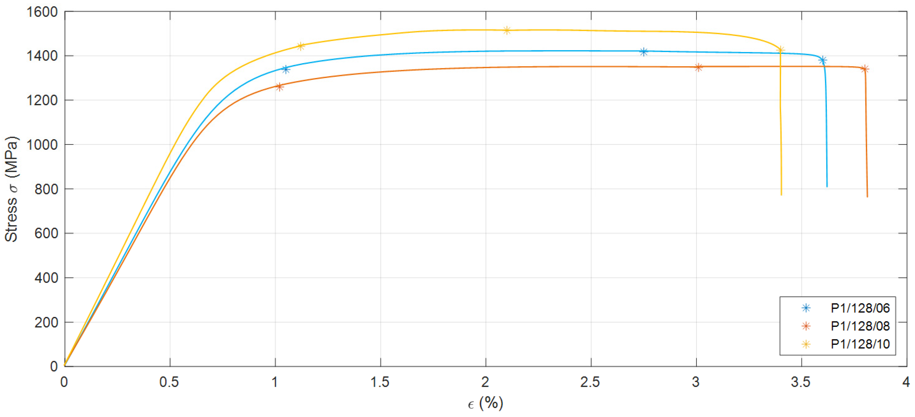
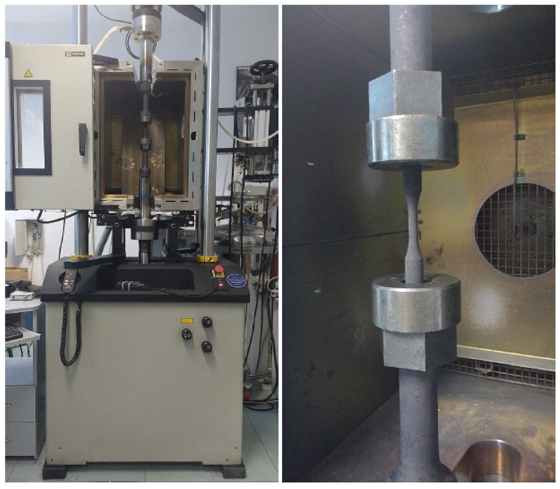
3.1. Tensile Testing

The static tensile test was performed using an Instron 3382 machine. The tests were carried out on 10 samples of circular cross section with a nominal initial diameter of d0 = 6 mm, a nominal length of the measuring section of l0 = 25 mm, and an as-built surface finish of Ra 5–12 µm. Each sample had a unique name, for example, P1/128/01, etched on by a laser machine. The samples were printed by an SLM 250 machine with a 50 µm layer thickness setup. The tests were carried out at room temperature according to the standard PN-EN ISO 6892-1: 2016-09. The test results are presented in Table 2. When analyzing the obtained results, it was observed that the elongation under fracture (parameter A) varied from 1.2% to 6.9%, while diameter reduction (parameter Z) varied between 5% and 21%. The parameter R0.2 is the 0.2% offset yield strength. Additionally, for some samples, the curves of the change in internal stress in the sample as a function of strain were recorded (Figure 1).
Comparing the obtained results with the technical specifications of maraging steels produced in a conventional manner, the tensile strength of the printed samples in this case was comparable to that of 18Ni1400 and approximately 16% lower than that of 18Ni1700.

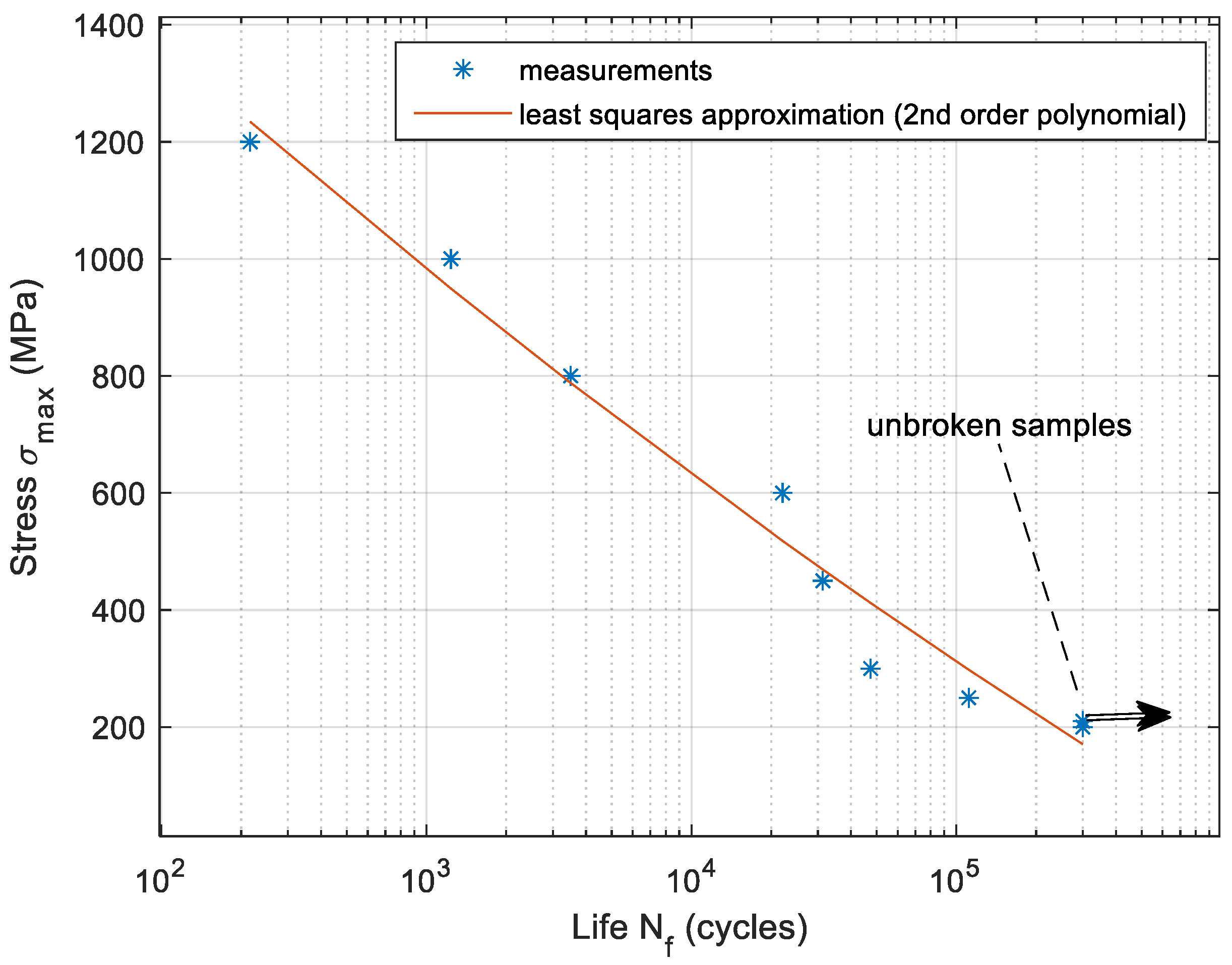
3.2. Tensile Fatigue Testing

Fatigue tests were carried out using an Instron 8801 machine (Figure 2) on samples of circular cross section with an as-built surface finish and a 50 µm layer setup, the shapes and dimensions of which were in accordance with the ASTM E466-15 standard. The build orientation of the specimens was 0 degrees with respect to the sample’s longitudinal axis. The tests were carried out at room temperature with a cyclically changing load at a frequency f = 3 Hz. The stresses arising in the sample were defined as one-sided tension with a cycle asymmetry R = 0.05. The results of measured minimum stress σmin and maximum stress σmax in the sample for fatigue life (Nf) are presented in Table 3. These parameters were used to determine the S–N curve (Figure 3).
Comparison of the obtained results with the literature data revealed that the samples made with the additive technologies were damaged at a much lower load. Based on the test results at 300,000 cycles, it can be concluded that the AM samples were approximately 16% less resistant to fatigue compared with the weakest maraging steels.

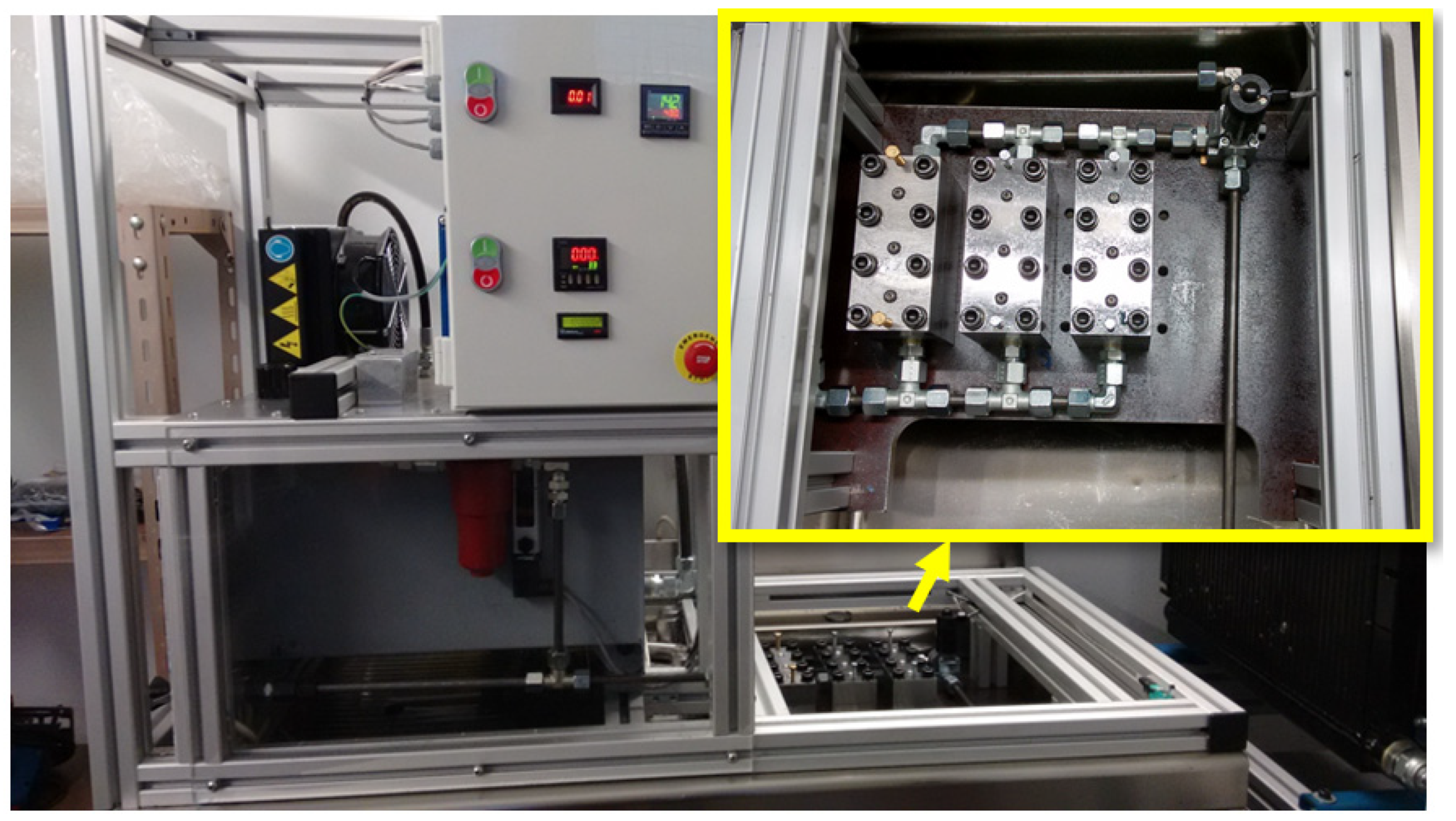
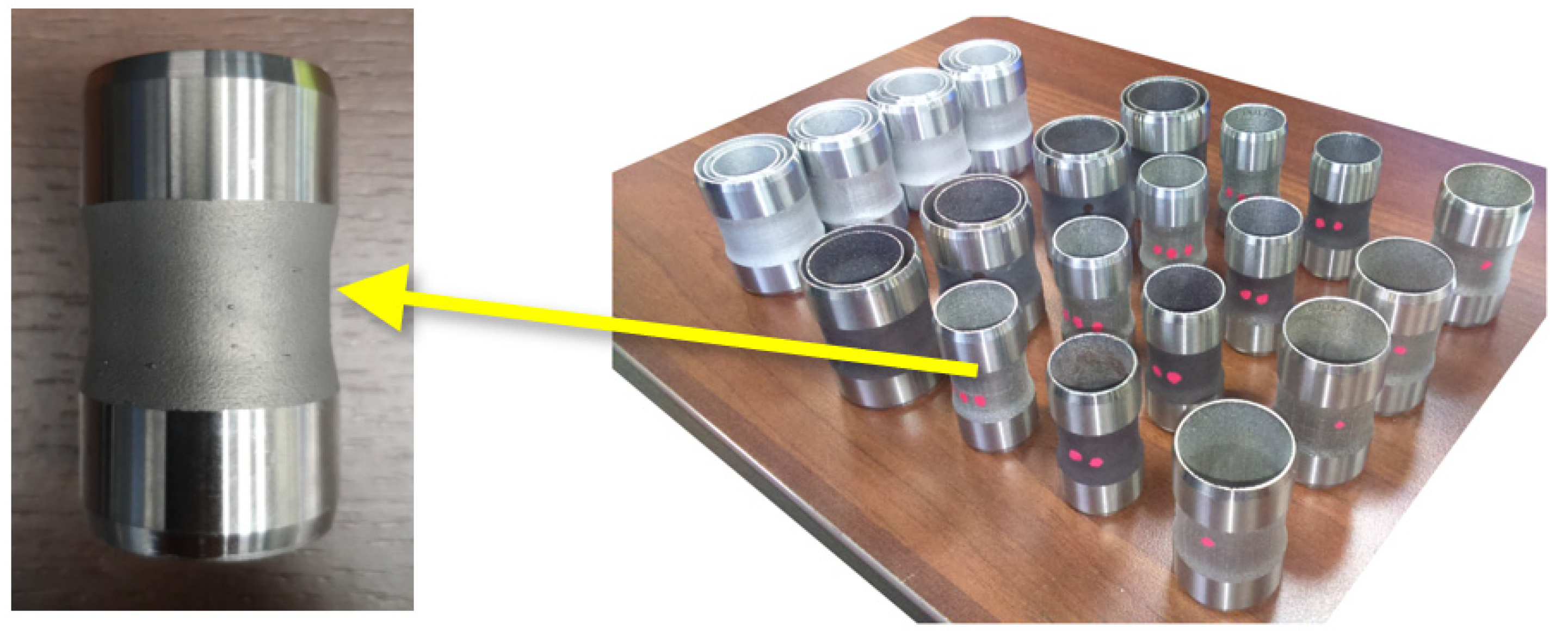
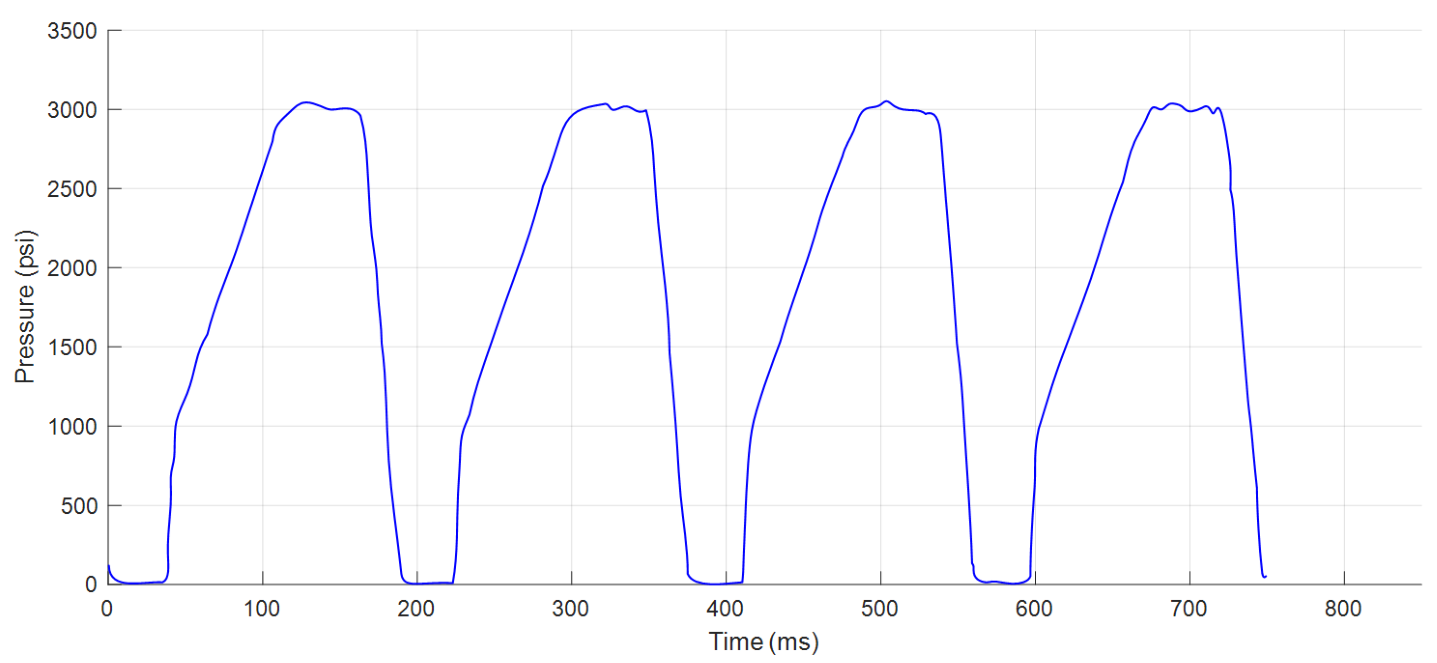
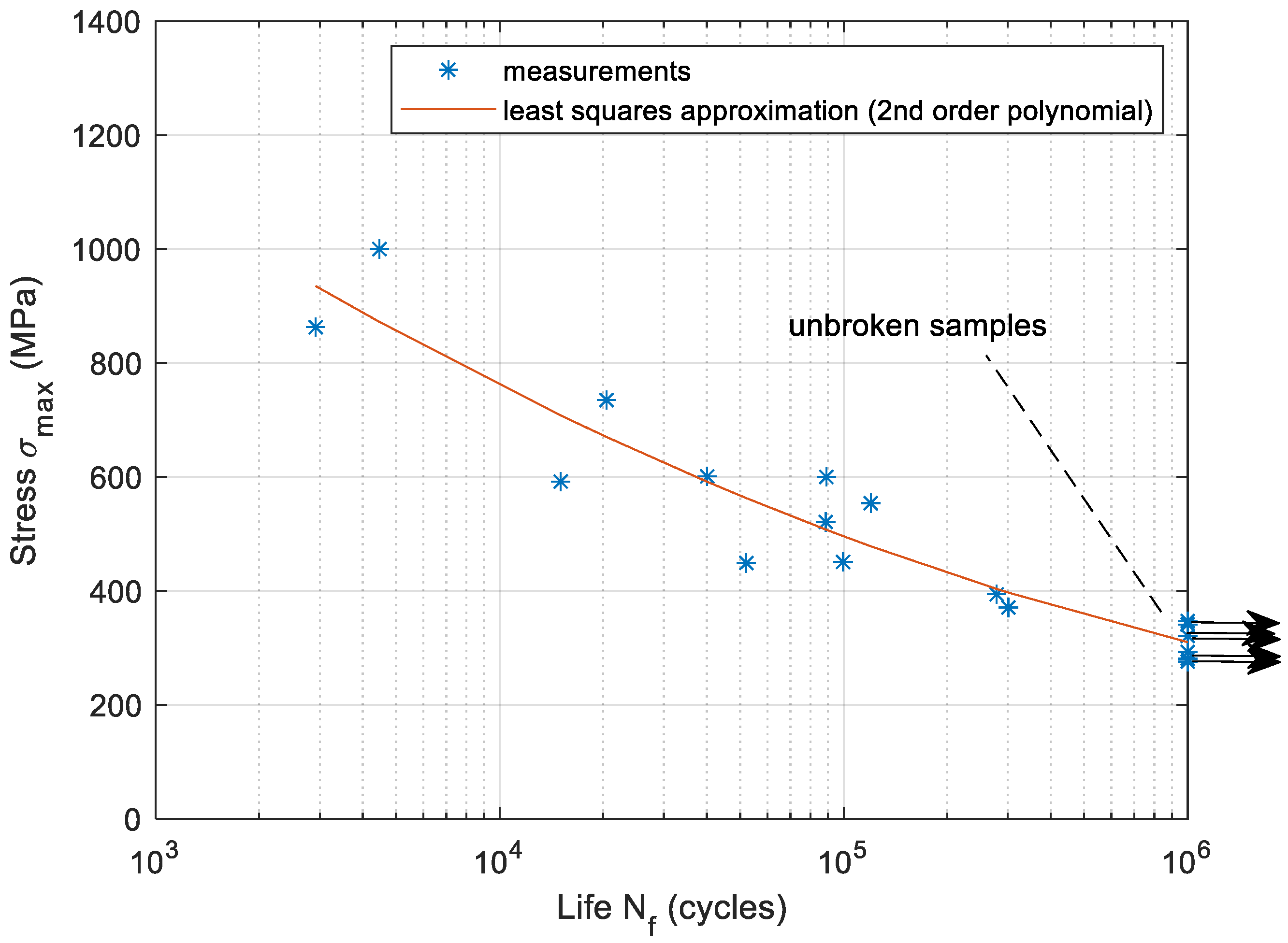
3.3. Pressure Fatigue Testing

The pressure fatigue tests were carried out on a test rig (Figure 4). The internal diameters of the samples (Figure 5) were 22, 27, and 33 mm and the wall thicknesses were 0.4, 0.5, and 0.6 mm. The build orientation of the sleeves was 0 degrees with respect to the sample’s rotational axis. The samples were sandblasted and machined to achieve good sealing surfaces, leaving the internal and external cross sections in the middle with an as-built surface finish and a 50 µm layer setup. The samples were placed in a steel block in the test chamber of the rig. On the basis of the measurement of the hydraulic oil pressure, the cylindrical stresses were determined using the following relationship:
σ θ = P d 2 t
where σ θ is cylindrical stress, P is pressure, d is internal diameter, and t is wall thickness.
The stresses arising in the sample were controlled by the maximum values of the pressure pulses (Figure 6) at a frequency f = 5 Hz. The control system counted the pressure pulses until the sample was broken. The results of the pressure fatigue tests are presented in Table 4. Based on Table 4, the S–N curve was created (Figure 7). The pressure fatigue endurance limit was more than 50% higher in comparison with tensile tests of the AM samples.

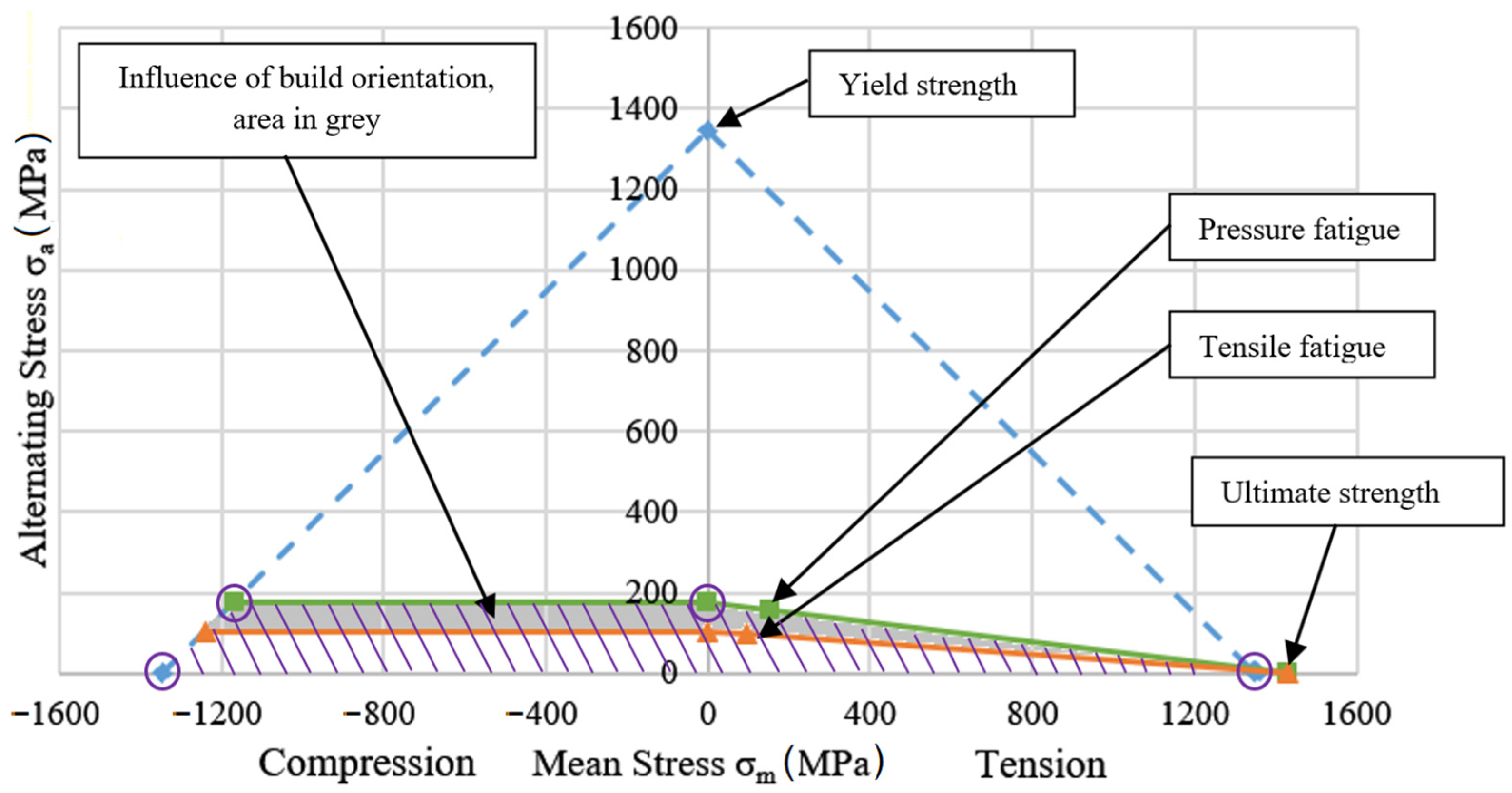
3.4. Goodman Diagram for Designing AM Maraging Steel Components for Fatigue

The data from the tensile and fatigue testing were used to plot the Goodman diagram as a reference for engineers who are involved in additive manufacturing design processes. The yield strength, ultimate strength, and endurance limit points were calculated in Table 5 and plotted in Figure 8.
The Goodman diagram shows the influence of build orientation on the fatigue properties. AM parts that were loaded in the same direction as the build orientation indicated lower fatigue strength. This effect is widely known in AM technology, and has been extensively analyzed in the literature [36,37,38,39]; however, the diagram presented in Figure 8 is the quantitative result obtained by the authors of the work in relation to the selected material and technology in which the presented actuators are made.

4. The Use of SLM Technology in the Production of Aviation Hydraulic Parts

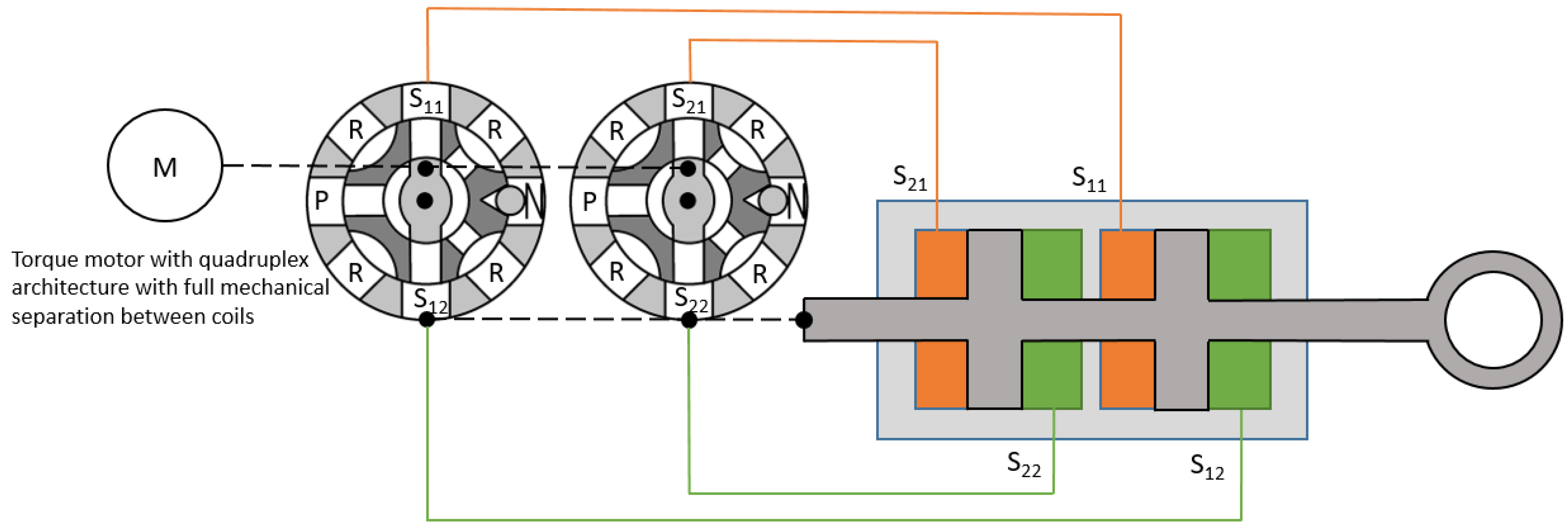
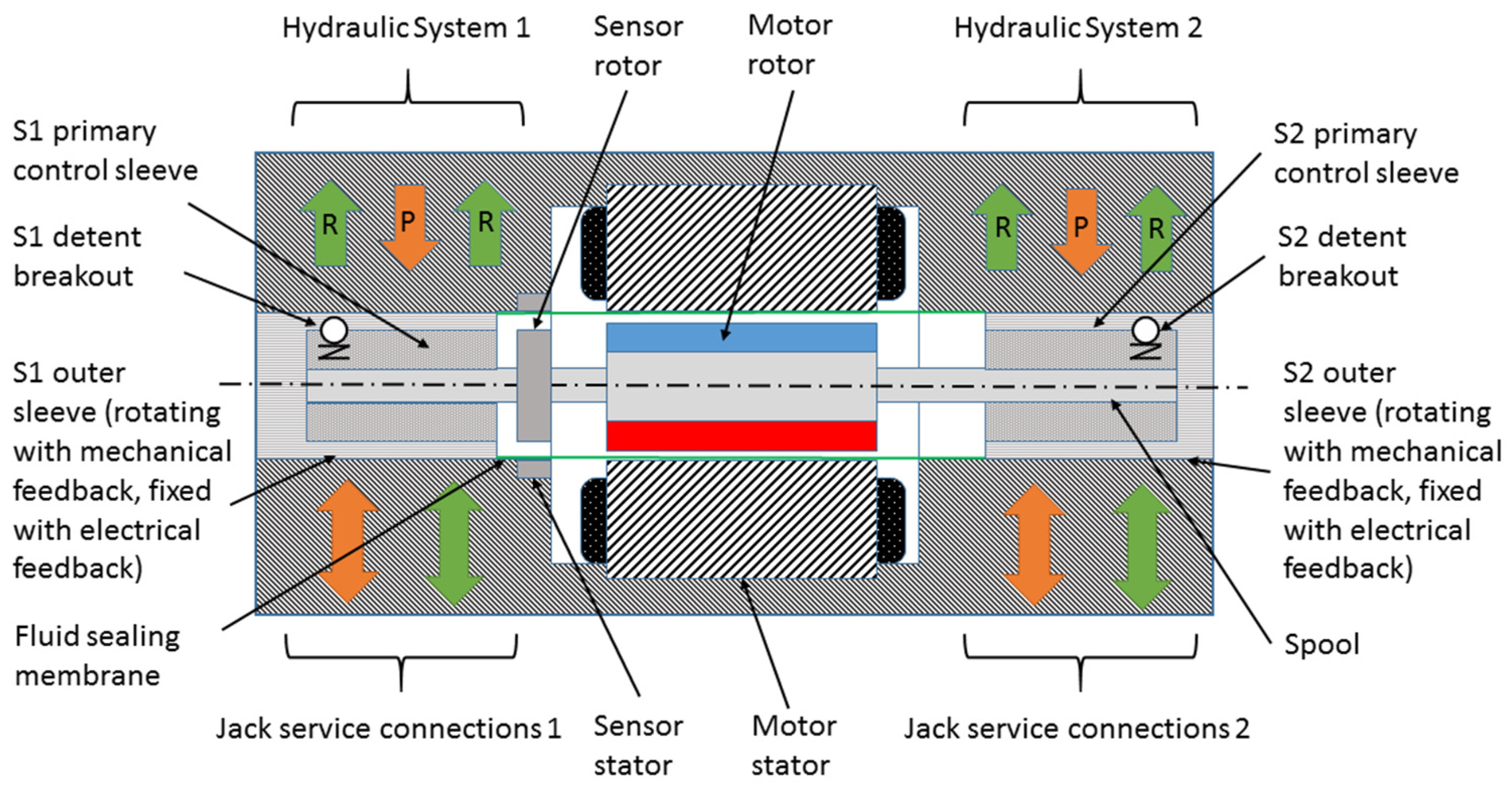
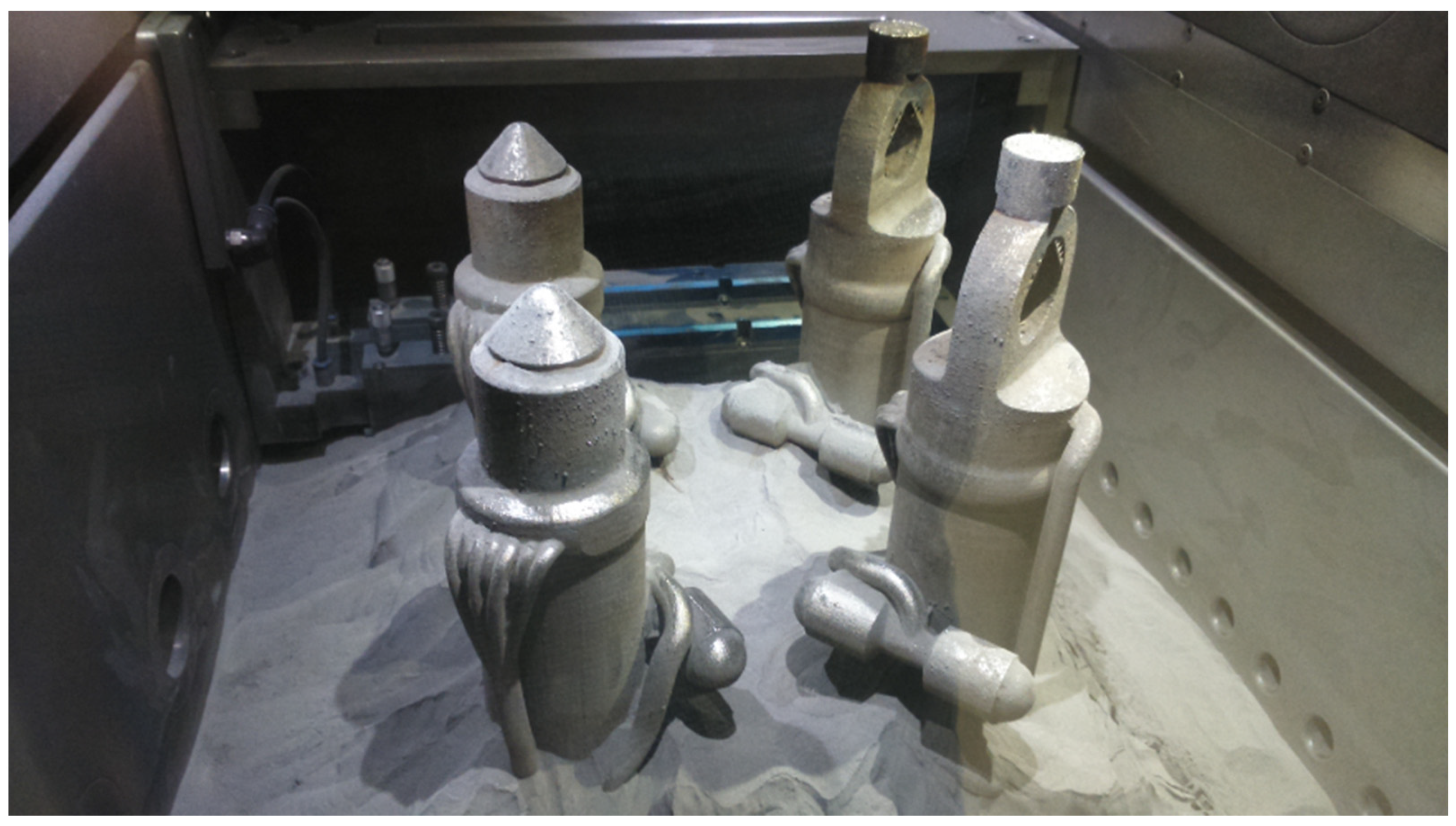
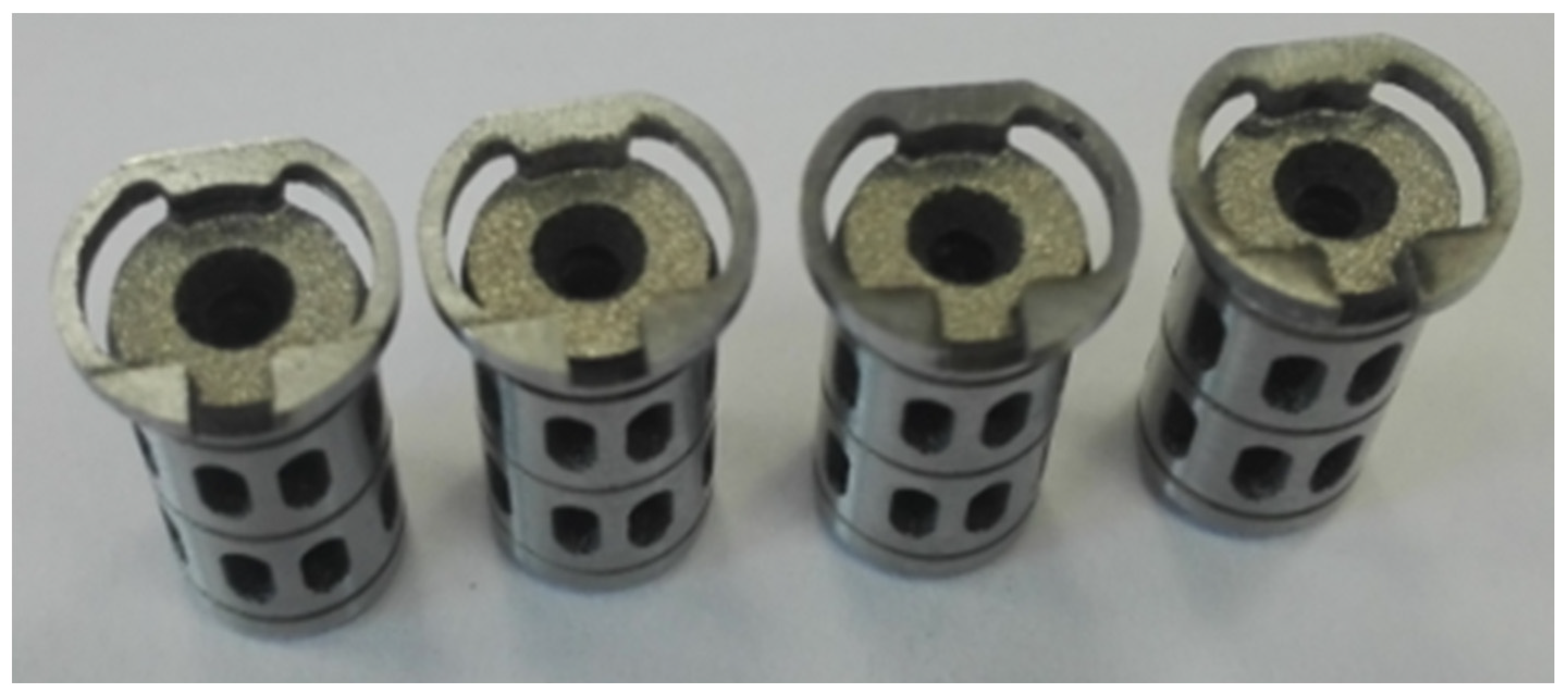
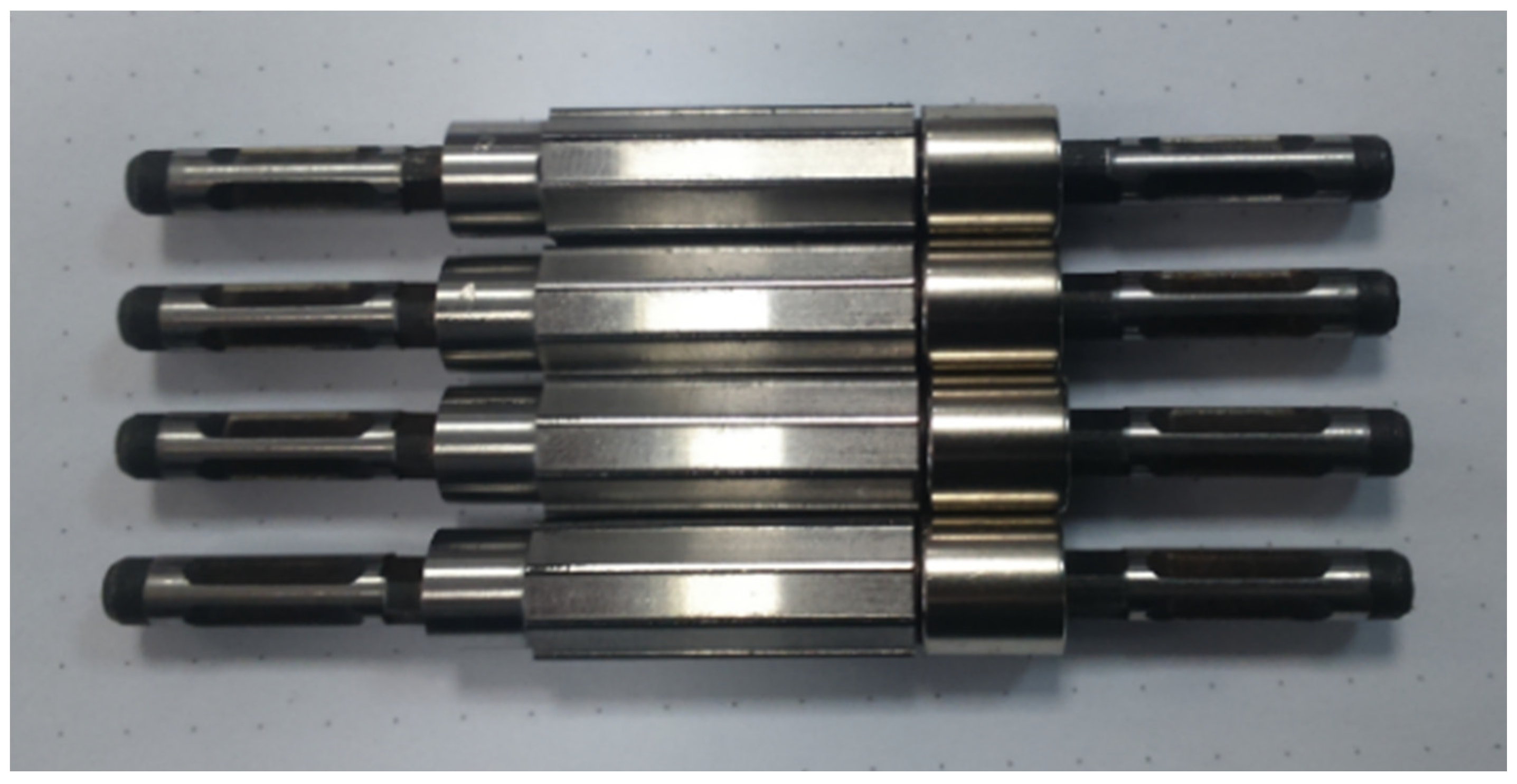
4.1. The Process of Manufacturing and Integrating the Hydraulic Actuator

Based on the research carried out on the strength of the AM samples, the aircraft flight control actuator was designed to achieve the highest level of safety integrity along with the greatest simplicity and lowest weight. The architecture aims to simplify the methods of failure detection, which need to be included within the flight control computer [31,32,33,34,35,36,37,38,39,40,41,42,43]. The general schematic of the flight control actuator (FCA) is presented in Figure 9. The servo actuator system is a dual tandem configuration with a hydro-mechanical anti-jam mechanism. It has two direct-drive servo valves with mechanical feedback linkage from the main ram to the secondary outer sleeve of the servo valve.
The center manifold is a key part of the actuator. It contains a rotary torque motor, two rotary spools, two sleeves, and position sensors coupled on one shaft. The electronic system is a fully quadruplex architecture and is fail operational even in the event of three failures. It includes a redundant three-phase channel motor with independent drives for each control lane. Each of the stator sectors is mechanically separated and capable of driving the load of the rotor in the event of failure. All hydraulic elements inside the valve are pressure- and flow-balanced in order to achieve low friction and hysteresis. The servo valve cross section schema is presented in Figure 10.
A dual hydraulic arrangement with independent valves allows one failure—either mechanical or hydraulic—without performance loss. The actuator receives four electrical command signals and two hydraulic supplies. The actuator can produce ram displacement in response to electrical command signals and continue operation after the failure of any input or internal part.
FCAs are complex items. The use of AM technology has significantly influenced the design and manufacture of many complex components included within the assembly of the actuator to meet the rigorous safety-critical requirements. Selected elements of FCAs manufactured by AM technology and the full assembly of the complete actuator are presented in Figure 11, Figure 12, Figure 13 and Figure 14. The presented FCA is lighter and has fewer parts [42]. It is approximately half the weight of the equivalent mechanical servo and less than half the weight of any FBW alternative.

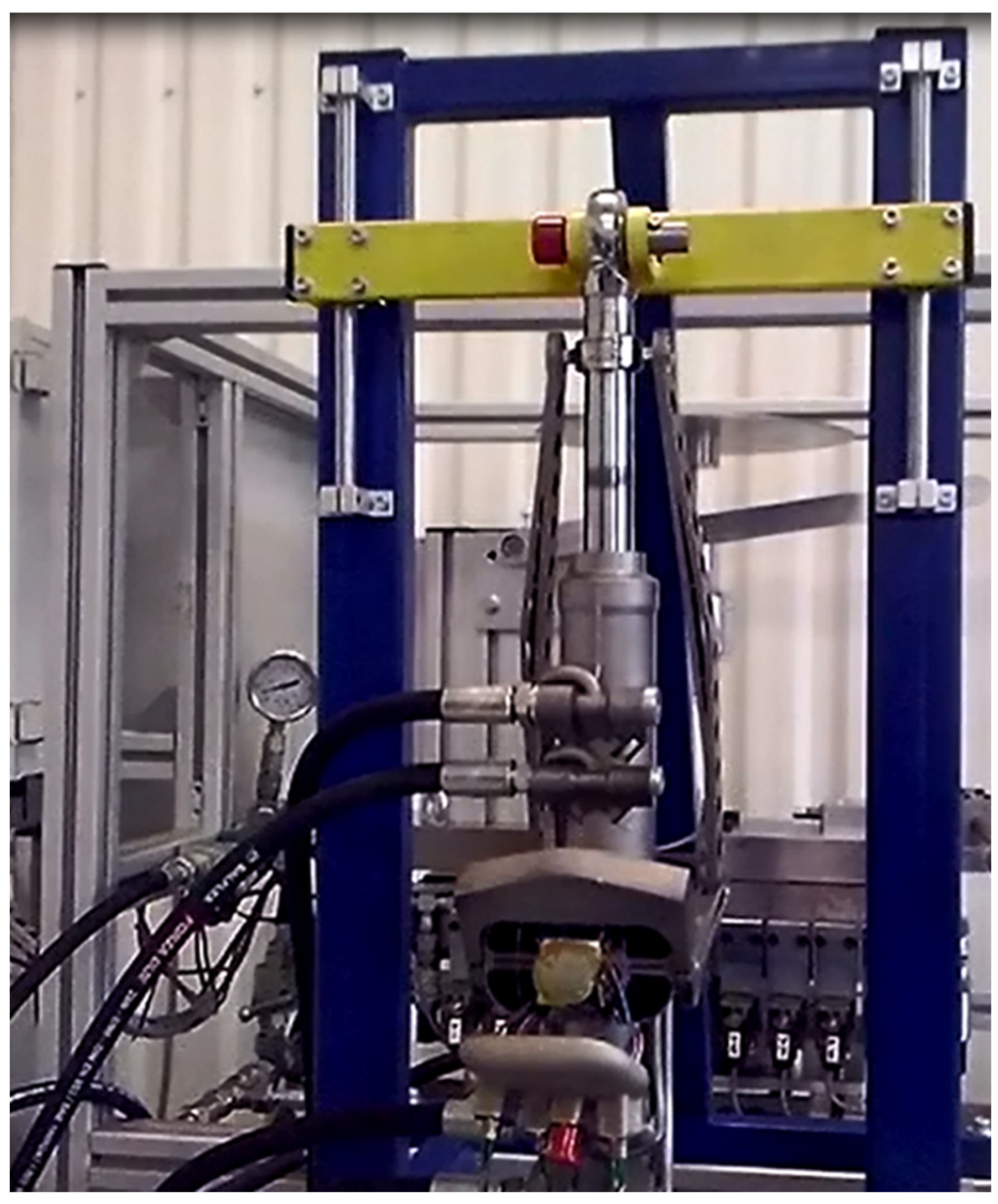
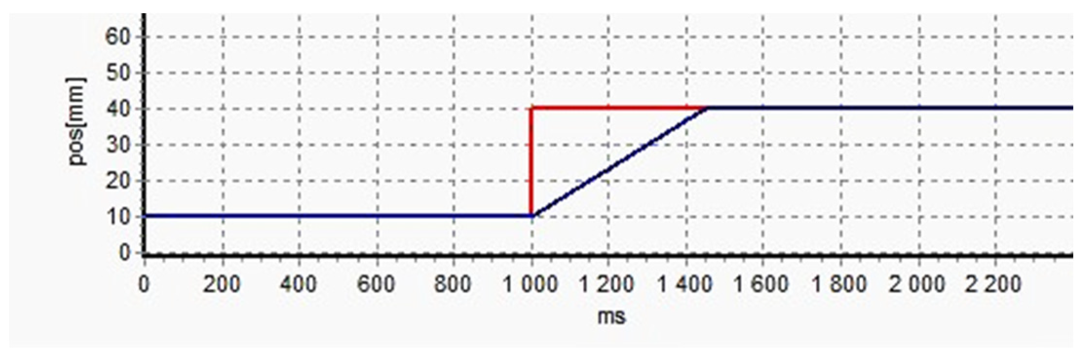
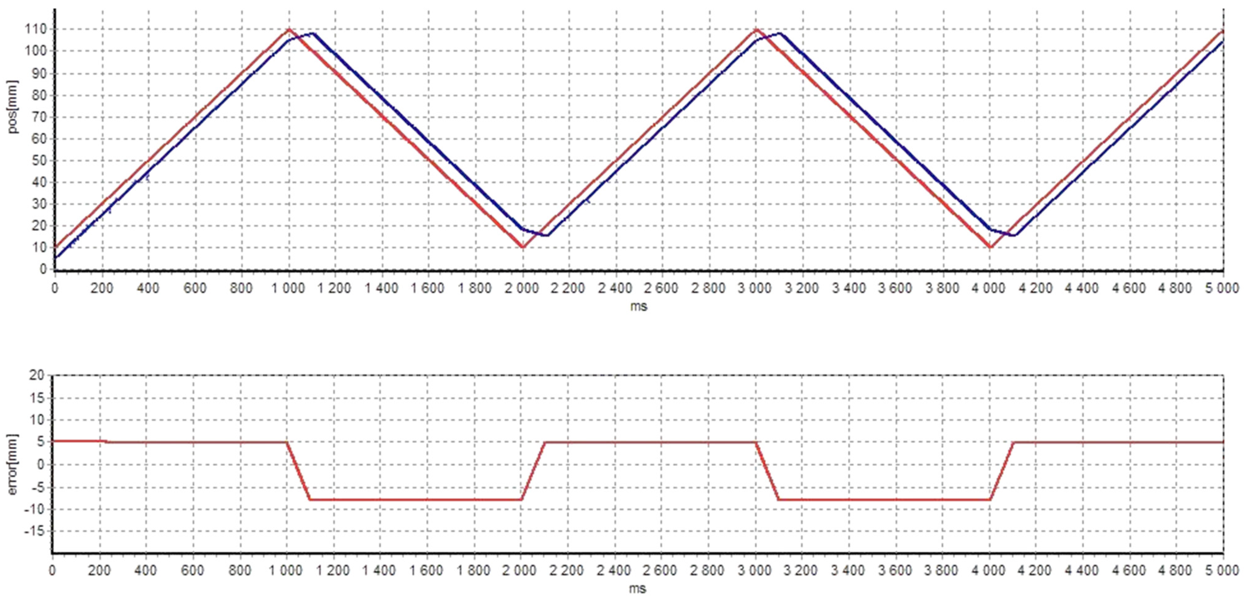
4.2. Results of the Preliminary Dynamic Tests

The complete mechanical prototype of the actuator was prepared for initial dynamic tests (Figure 15). These tests were performed with an operating pressure limited to 100 bar. A dedicated electro-mechanism was used for the positioning of the piston rod, together with a proprietary control and measuring system. The obtained actuator responses to the step input and the sawtooth input are shown in Figure 16 and Figure 17. The analysis of the step characteristic shows that with the limited working pressure, the actuator movement speed was approximately 75 mm/s (the full range of movement is 140 mm). For a sawtooth excitation, the delay was tens of milliseconds and the error in the actuator dynamic response was not greater than 7.5 mm (Figure 17). Detailed and complete tests of the actuators will be possible only after the completion of the work related to the dedicated control system. The development of an actuator control system is a complex and interdisciplinary issue. The effective dynamics of the actuator in its final form will result from both its mechanical properties and the properties of the controller itself.

5. Conclusions

This study investigated the use of SLM technology in the production of aviation hydraulic parts. The results of the static tensile tests indicated that parts produced by SLM achieved similar tensile strength to the maraging steel 18Ni1400 produced in a conventional manner. Comparison of the tensile fatigue results with the literature data revealed that the samples made with the additive technologies were broken at a lower load. Based on the test results at 300,000 cycles, it can be concluded that the AM samples are approximately 16% less resistant to fatigue compared with the weakest maraging steels.
A Goodman diagram was plotted to visualize the impact of the building orientation vs. the load character on the fatigue strength of the AM specimens. Directions of load, stress, and building orientation in the samples tested for tensile fatigue were 0 degrees with respect to the specimen’s longitudinal axis, and these specimens achieved a lower number of cycles to failure in comparison with pressure fatigue specimens. In contrast to the tensile testing, the pressure acting on the internal wall of the sleeves generated circumferential hoop stresses at 90 degrees to the specimen’s build direction. The analysis of the fatigue tests shows that the fatigue limit cannot be strictly determined and is highly dependent on the load vs. the built direction. These findings are consistent with other research and relevant literature [24,44].
The application of additive technologies in aviation may completely redefine the design and manufacture of advanced hydraulic aircraft control systems; however, the design process should be well integrated with the manufacturing process. The build orientation and character of load, as seen in the Goodman diagram in Figure 10, can be used as a tool for designing parts for fatigues. The authors prepared this diagram based on experimental data, and it is valid for steel 1.2709. SLM technology allows the manufacture of components with functional and complex internal structures, such as channels and flow-through bores, with weights decreased by up to 50%.
All dual servo valve ports were printed and directly connected with the external hydraulic ports on the actuator housing by complex internal galleries, allowing full redundancy of the system and complete mechanical separation of the flow paths [42]. Changing the cross-sectional area of the internal ports enabled the packing of two hydraulic servo valves and anti-jam control sleeves into a center gland housing with an unprecedented level of integration. This approach to designing hydraulic parts could revolutionize fluid power systems and significantly increase their potential in the aerospace industry. The use of 3D printing allows for significant reductions in the number of parts required for larger assemblies. The manufacture of parts by means of the technology in question decreases the usage of the target material, and thus the waste material (the turnings) is reduced to a minimum.

Author Contributions

Conceptualization, K.W., J.S., and P.B.; methodology, K.W., J.S., and P.B.; software, K.W., J.S., and P.B.; validation, K.W., J.S., and P.B.; formal analysis, K.W., J.S., P.B., and P.R.; investigation, K.W., J.S., and P.B.; resources, K.W., J.S., and P.B.; data curation, K.W., J.S., and P.B.; writing—original draft preparation, K.W. and P.R.; writing—review and editing, P.R. and T.R.; visualization, K.W., J.S., P.B., and P.R.; supervision, P.B., P.R., and T.R.; project administration, P.B.; funding acquisition, P.B. All authors have read and agreed to the published version of the manuscript.

Funding

The article has been realized within the framework of the project New generation of the hydraulic cylinder FBW made with application of Additive Manufacturing and machining technology at low temperatures (cryogenics)—co-financed by the INNOLOT Program 1/1.2/2015/POIR; measure 1.2: sectoral R&D programs 2014–2020, project No. POIR.01.02.00-00-0010/15.

Institutional Review Board Statement

Not applicable.

Informed Consent Statement

Not applicable.

Data Availability Statement

Data sharing is not applicable to this article.

Conflicts of Interest

The authors declare no conflict of interest.

References

  1. Di Rito, G. Experiments and simulations for the study of temperature effects on the performances of a fly-by-wire hydraulic actuator. Proc. Inst. Mech. Eng. Part I J. Syst. Control. Eng. 2011, 225, 1195–1206. [Google Scholar] [CrossRef]
  2. Zhao, Z.; Yu, X.; Zhang, Z.; Shu, W.; Li, J. Attempting AG-Doped Diamond-Like Carbon Film to Improve Seal Performance of Hydraulic Servo-Actuator. Materials 2020, 13, 2618. [Google Scholar] [CrossRef] [PubMed]
  3. Di Rito, G.; Galatolo, R. Experimental assessment of the dynamic stiffness of a fault-tolerant fly-by-wire hydraulic actuator. Proc. Inst. Mech. Eng. Part G J. Aerosp. Eng. 2012, 226, 679–690. [Google Scholar] [CrossRef]
  4. Garza, P.; Perinpanayagam, S.; Aslam, S.; Wileman, A. Qualitative Validation Approach Using Digital Model for the Health Management of Electromechanical Actuators. Appl. Sci. 2020, 10, 7809. [Google Scholar] [CrossRef]
  5. Huang, L.; Yu, T.; Jiao, Z.; Li, Y. Active Load-Sensitive Electro-Hydrostatic Actuator for More Electric Aircraft. Appl. Sci. 2020, 10, 6978. [Google Scholar] [CrossRef]
  6. Rahrovi, B.; Mehrdad, E. A review of the more electric aircraft power electronics. In Proceedings of the 2019 IEEE Texas Power and Energy Conference (TPEC), College Station, TX, USA, 7–8 February 2019. [Google Scholar]
  7. Hospodka, J.; Bínová, H.; Pleninger, S. Assessment of All-Electric General Aviation Aircraft. Energies 2020, 13, 6206. [Google Scholar] [CrossRef]
  8. Thapa, N.; Ram, S.; Kumar, S.; Mehta, J. All electric aircraft: A reality on its way. Mater. Today Proc. 2021, 43, 175–182. [Google Scholar] [CrossRef]
  9. Vedova, M.D.L.D.; Germanà, A.; Berri, P.C.; Maggiore, P. Model-Based Fault Detection and Identification for Prognostics of Electromechanical Actuators Using Genetic Algorithms. Aerospace 2019, 6, 94. [Google Scholar] [CrossRef] [Green Version]
  10. Chudý, P.; Tomczyk, A.; Rzucidlo, P. Safety enhanced digital flight control system. Aircr. Eng. Aerosp. Technol. 2009, 81, 416–423. [Google Scholar] [CrossRef]
  11. Wang, X.; Liao, R.; Shi, C.; Wang, S. Linear Extended State Observer-Based Motion Synchronization Control for Hybrid Actuation System of More Electric Aircraft. Sensors 2017, 17, 2444. [Google Scholar] [CrossRef] [PubMed] [Green Version]
  12. Lee, Y.-B.; Park, J.-W.; Lee, G.-C. A Study on Failure Analysis and High Performance of Hydraulic Servo Actuator. Appl. Sci. 2020, 10, 7451. [Google Scholar] [CrossRef]
  13. Jani, D.B.; Ashish, S.; Aditya, S.; Yash, S.; Bishambhar, S.; Nikhil, S.; Manmohan, S. An overview on aircraft hydraulic system. Renew. Sustain. Energy Rev. 2019, 6, 29–35. [Google Scholar]
  14. Han, C.; Kim, K. A Study on the Reliability and Maintainability Analysis Process for Aircraft Hydraulic System. J. Korea Soc. Syst. Eng. 2016, 12, 105–112. [Google Scholar] [CrossRef] [Green Version]
  15. Sun, X.; Wang, X.; Lin, S. Multi-Fault Diagnosis Approach Based on Updated Interacting Multiple Model for Aviation Hydraulic Actuator. Information 2020, 11, 410. [Google Scholar] [CrossRef]
  16. AF-9 Skydrol Overview, Eastman Chemical Company. Available online: https://www.eastman.com/Brands/EAS/Products/Pages/Skydrol.aspx (accessed on 15 March 2021).
  17. Helwig, A.; Müller, G.; Paul, S. Health Monitoring of Aviation Hydraulic Fluids Using Opto-Chemical Sensor Technologies. Chemosensors 2020, 8, 131. [Google Scholar] [CrossRef]
  18. Hueber, C.; Horejsi, K.; Schledjewski, R. Review of cost estimation: Methods and models for aerospace composite manufacturing. Adv. Manuf. Polym. Compos. Sci. 2016, 2, 1–13. [Google Scholar] [CrossRef]
  19. Aerospace: Liebherr—First Metal 3D Printed Primary Flight Control Hydraulic Component Flies on an AIRBUS A380. Available online: https://rmsiberia.com/aerospace-liebherr-first-metal-3d-printed-primary-flight-control-hydraulic-component-flies-on-an-airbus-a380/ (accessed on 15 March 2021).
  20. Antunes, F.; Santos, L.; Capela, C.; Ferreira, J.; Costa, J.; Jesus, J.; Prates, P. Fatigue Crack Growth in Maraging Steel Obtained by Selective Laser Melting. Appl. Sci. 2019, 9, 4412. [Google Scholar] [CrossRef] [Green Version]
  21. Cheng, C.-W.; Jian, W.-Y.J.; Makala, B.P.R. Selective Laser Melting of Maraging Steel Using Synchronized Three-Spot Scanning Strategies. Materials 2021, 14, 1905. [Google Scholar] [CrossRef] [PubMed]
  22. Saracyakupoglu, T. The Qualification of the Additively Manufactured Parts in the Aviation Industry. Am. J. Aerosp. Eng. 2019, 6, 1–10. [Google Scholar] [CrossRef]
  23. Kučerová, L.; Zetková, I.; Jeníček, Š.; Burdová, K. Production of Hybrid Joints by Selective Laser Melting of Maraging Tool Steel 1.2709 on Conventionally Produced Parts of the Same Steel. Materials 2021, 14, 2105. [Google Scholar] [CrossRef]
  24. Jarfors, A.E.W.; Shashidhar, A.C.G.H.; Yepur, H.K.; Steggo, J.; Andersson, N.-E.; Stolt, R. Build Strategy and Impact Strength of SLM Produced Maraging Steel (1.2709). Metals 2021, 11, 51. [Google Scholar] [CrossRef]
  25. Tyczyński, P.; Siemiątkowski, Z.; Bąk, P.; Warzocha, K.; Rucki, M.; Szumiata, T. Performance of Maraging Steel Sleeves Produced by SLM with Subsequent Age Hardening. Materials 2020, 13, 3408. [Google Scholar] [CrossRef] [PubMed]
  26. Kleemann, E.; Dey, D.; Recksiek, M.; DaimlerChrysler Aerospace. The development of a civilian fly by wire flight control system. Proceedings of ICAS Congress ICAS, Harrogate International Conference Centre, Harrogate, UK, 7 August–1 September 2000. [Google Scholar]
  27. Lu, Z.; Zhuang, L.; Dong, L.; Liang, X. Model-Based Safety Analysis for the Fly-by-Wire System by Using Monte Carlo Simulation. Processes 2020, 8, 90. [Google Scholar] [CrossRef] [Green Version]
  28. Jacazio, G.; Gastaldi, L. Robust pressure control improves the performance of redundant fly-by-wire hydraulic actuators. Int. J. Appl. Eng. Res. 2016, 11, 8590–8597. [Google Scholar]
  29. Dołęga, B. Some remarks about aircraft control and navigation system as reliable fault tolerant system. Pomiary Autom. Kontrola 2011, 57, 1024–1027. [Google Scholar]
  30. Dołęga, B.; Rzucidło, P. Controllers for fault tolerant actuators. Aviation 2007, 11, 23–27. [Google Scholar] [CrossRef]
  31. Sendeckyj, G.P. Constant life diagrams—A historical review. Int. J. Fatigue 2001, 23, 347–353. [Google Scholar] [CrossRef] [Green Version]
  32. Jimenez-Vicaria, J.D.; Gomez-Pulido, M.D.; Castro-Fresno, D. Numerical and Experimental Evaluation of a CFRP Fatigue Strengthening for Stringer-Floor Beam Connections in a 19th Century Riveted Railway Bridge. Metals 2021, 11, 603. [Google Scholar] [CrossRef]
  33. Dobrzański, L.A. Metal i ich Stopy; International OCSCO World Press: Gliwice, Poland, 2017. [Google Scholar]
  34. 18 Percent Nickel Maraging Steels, Engineering Properties; Publication No. 4419; Nickel Development Institute: Toronto, CA, USA, 1976.
  35. Vock, S.; Klöden, B.; Kirchner, A.; Weißgärber, T.; Kieback, B. Powders for powder bed fusion: A review. Prog. Addit. Manuf. 2019, 4, 383–397. [Google Scholar]
  36. Wauthle, R.; Vrancken, B.; Beynaerts, B.; Jorissen, K.; Schrooten, J.; Kruth, J.-P.; Van Humbeeck, J. Effects of build orientation and heat treatment on the microstructure and mechanical properties of selective laser melted Ti6Al4V lattice structures. Addit. Manuf. 2015, 5, 77–84. [Google Scholar] [CrossRef]
  37. Alfaify, A.; Saleh, M.; Abdullah, F.M.; Al-Ahmari, A.M. Design for Additive Manufacturing: A Systematic Review. Sustainability 2020, 12, 7936. [Google Scholar] [CrossRef]
  38. Mooney, B.; Kourousis, K.I. A Review of Factors Affecting the Mechanical Properties of Maraging Steel 300 Fabricated via Laser Powder Bed Fusion. Metals 2020, 10, 1273. [Google Scholar] [CrossRef]
  39. Konieczny, B.; Szczesio-Wlodarczyk, A.; Sokolowski, J.; Bociong, K. Challenges of Co-Cr Alloy Additive Manufacturing Methods in Dentistry—The Current State of Knowledge (Systematic Review). Materials 2020, 13, 3524. [Google Scholar] [CrossRef]
  40. Collins, A. Servo Actuators. England Patent WO2016/075491 A1, 19 May 2016. [Google Scholar]
  41. Yasa Flight Control. Available online: http://yasa-motors.com/wp-content/uploads/2017/05/FBW-brochure.pdf (accessed on 15 March 2021).
  42. Warzocha, K.; Bąk, P. Method for Manufacturing the Aircraft Valve Block. Poland Patent PL227484, 23 June 2017. [Google Scholar]
  43. Nicolin, I.; Nicolin, B.A. The fly-by-wire system. INCAS Bull. 2019, 11, 217–222. [Google Scholar] [CrossRef]
  44. Meneghetti, G.; Rigon, D.; Cozzi, D.; Waldhauser, W.; Dabala, M. Influence of build orientation on static and axial fatigue properties of maraging steel specimens produced by additive manufacturing. In Proceedings of the 3rd International Symposium on Fatigue Design and Material Defects, FDMD 2017, Lecco, Italy, 19–22 September 2017. [Google Scholar]
Figure 1. Tensile stress–strain curves.
Applsci 11 04772 g001
Figure 2. The laboratory test rig Instron 8801.
Applsci 11 04772 g002
Figure 3. The S–N curve for additively manufactured maraging steel, R = 0.05.
Applsci 11 04772 g003
Figure 4. The pressure fatigue test rig.
Applsci 11 04772 g004
Figure 5. Pressure fatigue samples.
Applsci 11 04772 g005
Figure 6. Pressure impulse waveform.
Applsci 11 04772 g006
Figure 7. The S–N curve for AM maraging steel for pressure fatigue load, R = 0.
Applsci 11 04772 g007
Figure 8. Goodman diagram obtained from fatigue and static testing of the maraging steel specimens produced by SLM.
Applsci 11 04772 g008
Figure 9. General schematic drawing of the FCA; own drawing based on patent [40] and Domin company materials [41].
Applsci 11 04772 g009
Figure 10. General schematic of the servo; own drawing based on patent [40] and Domin company materials [41].
Applsci 11 04772 g010
Figure 11. Manufacturing of actuator bodies with AM technology.
Applsci 11 04772 g011
Figure 12. Actuator components made with AM technology ready for integration: primary control sleeves.
Applsci 11 04772 g012
Figure 13. Actuator components made with AM technology ready for integration: primary control spools.
Applsci 11 04772 g013
Figure 14. Assembled fly-by-wire actuator manufactured with AM technology.
Applsci 11 04772 g014
Figure 15. The actuator prototype prepared for preliminary functional tests.
Applsci 11 04772 g015
Figure 16. The actuator response to the step input.
Applsci 11 04772 g016
Figure 17. The actuator response to a triangle-shaped input.
Applsci 11 04772 g017
Table 1. Chemical composition of the most popular maraging steels [33,34,35].
GradeWroughtCastAM Powder
18Ni140018Ni170018Ni190018Ni240017Ni1600M300/1.2709
Nominal 0.2% Proof Stress (MPa)140017001900240016001800
Ni17–1917–1918–1917–1816–17.517–19
Co8.0–9.07.0–8.58.0–9.512–139.5–11.08.5–9.5
Mo3.0–3.54.6–5.14.6–5.23.5–4.04.4–4.84.5–5.2
Ti0.15–0.250.3–0.50.5–0.81.6–2.00.15–0.450.6–0.8
Al0.05–0.150.05–0.150.05–0.150.1–0.20.02–0.10.05–0.15
Si max.0.120.120.120.10.10.1
Mn max.0120.120.120.10.10.1
C max.0.030.030.030.010.030.03
FeBalanceBalanceBalanceBalanceBalanceBalance
Table 2. Tensile testing results.
Sample No.R0.2 (MPa)Rm (MPa)A (%)Z (%)
P1/128/01131714322.918
P1/128/02135914505.121
P1/128/03144515304.421
P1/128/04130913971.25
P1/128/05153016032.813
P1/128/06133814176.810
P1/128/07126813362.85
P1/128/08125913476.06
P1/128/09120412874.88
P1/128/10144215146.913
Table 3. Tensile fatigue test results.
Sample No.σmax (MPa)σmin (MPa)Nf (Cycles)
R1/128/01120060216
R1/128/021000501237
R1/128/03800403504
R1/128/046003022,077
R1/128/0545022.531,324
R1/128/063001547,489
R1/128/0725012.5111,361
R1/128/0821010.5300,000 *
R1/128/0920010300,000 *
* - unbroken samples
Table 4. Pressure fatigue test results.
Sample No.t (mm)P (psi)σmax (MPa)Nf (Cycles)
X09370.4290059215,052
X09380.4360073520,452
X09390.4220044952,125
X09400.4489510004474
X09410.413752811,000,000 *
X09420.417003471,000,000 *
X09490.513752761,000,000 *
X09500.516003211,000,000 *
X09510.51850371301,249
X09520.5260052188,639
X09530.5225045199,572
X09540.5300060140,106
X09610.613752931,000,000 *
X09620.616003411,000,000 *
X09630.61850394278,403
X09640.62600554119,877
X09650.640508632920
X09660.6281660089,037
* - unbroken samples
Table 5. Calculated material data.
Mechanical DataAverage Stress ValuesMaximal Error
Yield strength1347 MPa13%
Ultimate strength1431 MPa12%
Tensile fatigue strength, mean, R = 0.0597 MPa8%
Pressure fatigue strength, mean, R = 0155 MPa11%
Publisher’s Note: MDPI stays neutral with regard to jurisdictional claims in published maps and institutional affiliations.

