Article

Multi-Structural Optimization of Bearingless Permanent Magnet Slice Motor Based on Virtual Prototype in Ansoft Maxwell

1
School of Mechanical Engineering, University of Shanghai for Science and Technology, Shanghai 200093, China
2
College of Mechanical and Electrical Engineering, Wenzhou University, Wenzhou 325035, China
3
State Key Laboratory of Fluid Power and Mechatronic Systems, School of Mechanical Engineering, Zhejiang University, Hangzhou 310027, China
*
Author to whom correspondence should be addressed.
Appl. Sci. 2021, 11(11), 4740; https://doi.org/10.3390/app11114740
Submission received: 15 April 2021 / Revised: 10 May 2021 / Accepted: 18 May 2021 / Published: 21 May 2021
(This article belongs to the Section Mechanical Engineering)

Abstract

:
As a preliminary study for bearingless permanent magnet slice motor (BPMSM) development, an effective means for BPMSM mechanical structure optimization is proposed here by developing a virtual prototype based on Ansoft Maxwell to realize overall performance improvements. First, the sensitivity evaluation index of the candidate mechanical structural parameters for individual BPMSM performance is constructed for selection. Orthogonal tests are performed to determine the dominant mechanical structural parameters to be optimized by utilizing monitored data based on Ansoft Maxwell. A linear regression model of the mechanical structural parameters for specific performances is obtained by utilizing the gradient descent method. Then, a multi-structural optimization regression model of the selected dominant mechanical structural parameters for overall performance is established using an analytic hierarchy process and solved using a genetic algorithm. The simulation results show that the performance of the optimized BPMSM has been comprehensively improved. Specifically, the passive axial stiffness, passive tilting stiffness, force-current coefficient, and motor efficiency increased by 56.4%, 71.3%, 19.6%, and 8.7%, respectively.

1. Introduction

As a new type of bearingless motor, a bearingless permanent magnet slice motor (BPMSM), not only inherits the advantages of wear-free, maintenance-free, long life, low noise and high precision, but also makes up for the shortcomings of a complex structure and high cost [1,2,3]. Nowadays, it has been widely applied in the medical industry, IC manufacturing, and aerospace. Researches on the optimization of BPMSMs has become a new hotspot in the fields of miniaturization, high-sealing performance, and ultra-cleanliness, which are of great significance.
In contrast to conventional motors, the mechanical setup of BPMSMs offers much more freedom in terms of constructive design. However, the design leads to a nonlinear flux and current distribution, resulting in a nonlinear force and torque generation [4]. In [5,6], the installation site of the rotor (internal rotor or external rotor) was changed to achieve optimal power between the bearing forces and motor torque. In [7], a bearingless slice motor with an external rotor design was introduced to realize linear force and torque generation behavior with the help of feedback control. For high-speed bearingless drive optimization, the number of rotor poles and stator slots as well as the winding arrangement were analyzed in [8,9]. With the increasing demands for canned pumps and chambers in the semiconductor manufacturing industry, bearingless slice motors with wide air gaps were proposed in [10,11]. To achieve a compact and lightweight design, symmetric sets of Halbach magnet arrays are often used in BPMSM structural designs [12,13]. Considering feasibility and efficiency, optimization relying on the performance measurements of laboratory prototypes always focuses on qualitative analyses. Systematic research with comprehensive considerations on BPMSM structural parameters, including the arrangement of stators and rotors, the winding configurations, the number of turns of the winding, and the structural style of the permanent magnets (PMs), face challenges from the point of view of system costs and the need for a high-purity experimental environment based on laboratory prototypes.
With the development of finite element analysis software, such as Ansoft and Ansys, the transient state union simulation technique has been adopted to analyze different motor structures, explore the general rule of the optimization of PMs and windings, and establish a general method for the static and dynamic analyses of the BPMSM. Some typical simulation methods have been utilized in the field of bearingless motor optimization over the past few decades [14,15,16,17,18]. Recently, vibration suppression methods along the axial and radial directions for BPMSMs were proposed in [19,20] using simulations. In addition, research on the material properties of bearingless motor parts, especially the rotor, were verified through simulations in [21,22]. As an alternative approach, electrical machine performance optimization through advanced control algorithms [23,24,25] can also realize improvements without high system costs for prototype development in physical modifications.
The aforementioned studies focused on the specific mechanical structural optimization of BPMSMs without improvements to the overall performance. Moreover, the mechanical structural parameter optimization of BPMSMs is a nonlinear, multivariable, multi-objective, and strongly-coupled comprehensive problem. As a preliminary study of BPMSMs, this paper presents the sensitivity evaluation index of candidate mechanical structural parameters for specific performance based on a virtual prototype developed in Ansoft Maxwell. The dominant structural parameters are selected to be optimized by performing orthogonal tests. Finally, based on the regression model and a genetic algorithm (GA), a multi-structural optimization method for BPMSMs is proposed. The optimization results are verified through simulation experiments. This paper is organized as follows:
-
Section 2 introduces the methodology, including the virtual prototype developed in Ansoft Maxwell and the optimization process architecture;
-
Section 3 presents the parameter assessment process for optimization, including performance evaluation and structural parameter sensitivity analysis;
-
Section 4 demonstrates the proposed multi-structural optimization method by utilizing a virtual prototype, and analyzes and discusses the optimization results;
-
Section 5 concludes the paper.

2. Methodology

2.1. Virtual Prototype of BPMSM

The optimized BPMSM prototype is a magnetically levitated centrifugal pump, BPS-200 of Levitronix™ (rated voltage = 24 V, rated speed = 8000 rpm, input power = 170 W). As presented in Figure 1a, the virtual prototype of the BPMSM developed in Ansoft Maxwell consists of stators, a slice rotor, levitation windings, and torque windings. The outer stators are folded down to form eight iron-core columns, while the slice rotor is a two-pole permanent magnet ring made of NdFeB. The magnetic circuit of the BPMSM forms a loop through the permanent magnet rotor, the iron-core columns, and the stator yoke. This structure makes one side of the BPMSM completely exposed, which facilitates the installation of the windings. This allows the two winding currents that generate the levitation force to be controlled separately. Furthermore, the two sets of windings are decoupled from each other electromagnetically. The slice shape rotor of the BPMSM can realize full suspension in five degrees of freedom (DOFs): passive levitation in an axial DOF and two axial-tilting DOFs, and active levitation in two radial DOFs on the xoy-plane. When the rotor is axially offset or twisted, the magnet flux in the BPMSM changes. With the principle of minimum magnetic reluctance, a magnetic force will be generated to pull the rotor back to its balance position.
Based on the virtual model, a coarse grid is first used for mesh generation, then the steady-state adaptive mesh is used. As presented in Figure 1b, the grid between different material structures is finer to ensure computation accuracy. Figure 1d,e displays the magnetic field distribution of BPMSM no-load and on-load conditions. For the former condition, the two-pole magnetic flux is symmetrical with the rotor in the equilibrium position. For the on-load condition, the magnetic flux is the combination of the symmetrical quadrupole magnetic field produced by the levitation force winding current and the symmetrical two-pole magnetic flux of the no-load condition. It can be observed that the magnetic density along the +x-axis is obviously larger than that of other parts, verifying a controllable radial suspension force generated along the +x-axis.
Referring to the traditional permanent magnet synchronous motor design method, the candidate mechanical structural parameters for BPMSM performance optimization are presented in Figure 1c. According to the design specifications where the rated power is Pe = 200 W, rated speed is nN = 8000 r/min, and rated efficiency is η = 65%, the initial values are listed in Table 1.

2.2. The Optimization Process Architecture

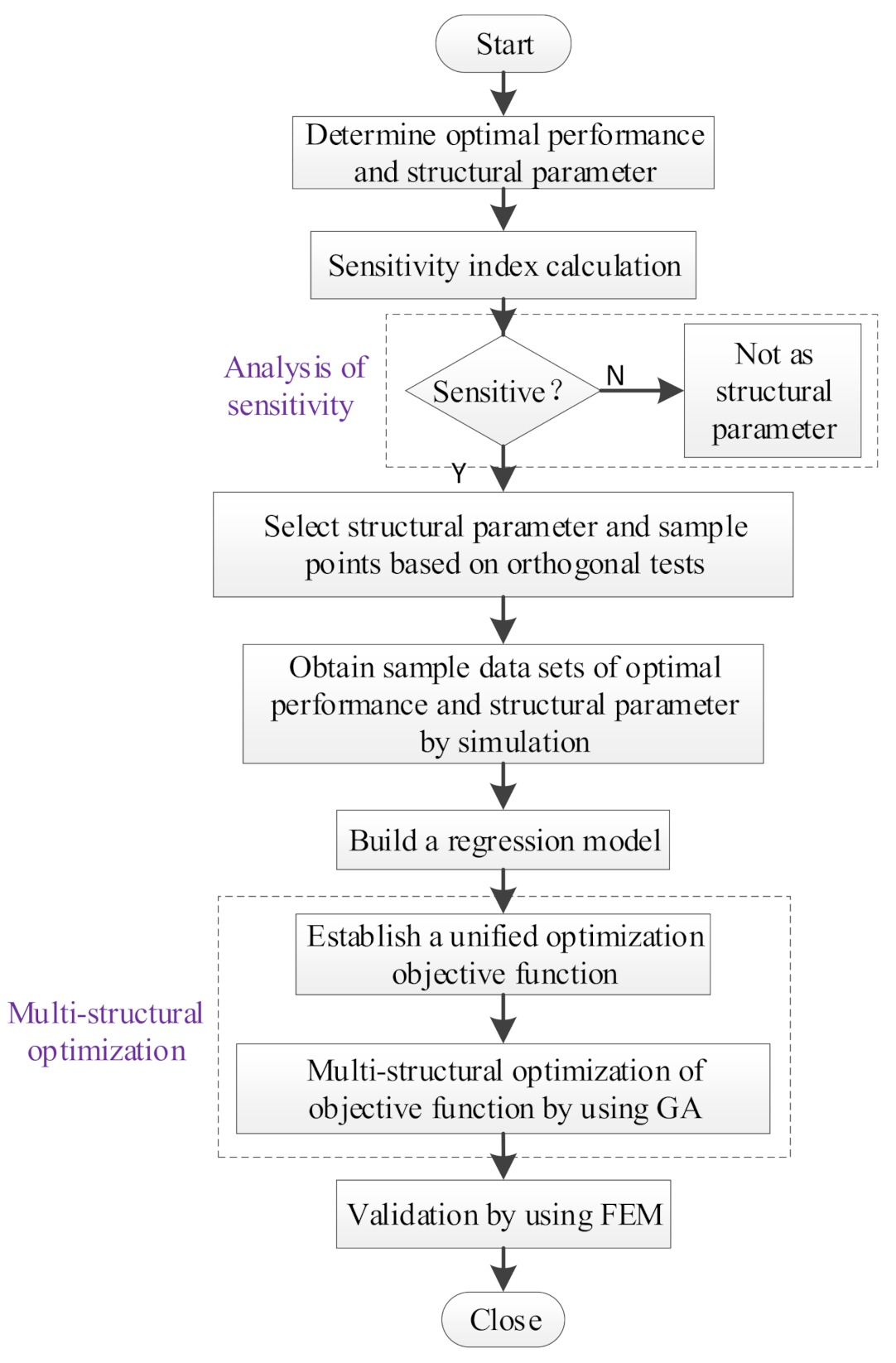
According to Table 1, in total, 14 parameters are involved in BPMSM structural design. To realize efficient performance improvements, the optimization process architecture is designed to focus on those dominant parameters. In the optimization process, the involved parameters and searching areas are determined by taking the motor design standard as the criterion, and the introduction of parametric modeling provides a basis for efficient and feasible comprehensive performance optimization. The optimization flowchart is presented in Figure 2:
-
First, BPMSM performances, as the optimization objects and the structural parameter candidates to be optimized, are specified.
-
Second, a sensitivity index is proposed to judge the effects of the different structural parameters on the optimized performance of the BPMSM to avoid contradictions in the optimization process, and the searching range is determined according to the working conditions of the motor and the difficulty of assembly.
-
Third, the orthogonal test method [26] is used out to efficiently extract representative sample data.
-
Then, the linear relationship between individual BPMSM performance and the chosen structural parameter is derived by using the gradient descent method for parametric optimization modeling.
-
Finally, a dimensionless multi-structural optimization model is developed based on the regression model and solved using a GA.

3. Parameter Assessment for Optimization

3.1. BPMSM Performance Evaluation

Based on the virtual prototype in Figure 1, the BPMSM performance is analyzed to determine the dominant characteristics and expressions. The performance analysis focuses on the core characteristics, including levitation capability, electromagnetic torque, and motor efficiency.
A.
Levitation Performance
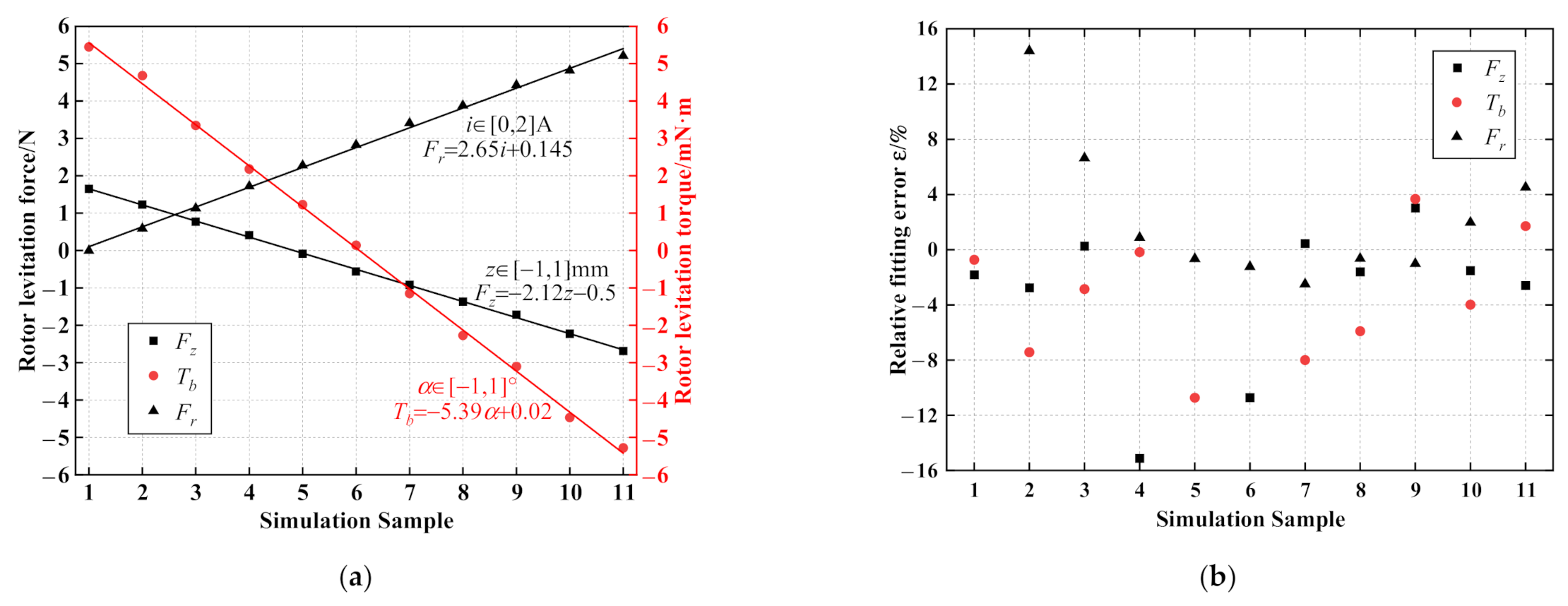
As shown in Figure 3a, the axial levitation force (Fz) of the BPMSM increases linearly with axial offsets (z) ranging from −1 to 1 mm, evenly, and the rotor tilting levitation torque (Tb) increases linearly with the tilting angle (α) ranging from −1° to 1°, evenly. Therefore, the axial levitation force (Fz) and the tilting levitation torque (Tb) can be linearized as:
F z = k z z
T b = k α α
By using least-square (LS) fitting, the linear expression of Fz is: y = −2.12x − 0.5 with kz = 2.12 N/mm, and the linear fitting expression of Tb is: y = ‒5.39x + 0.02 with kα = 0.309 N·m/rad.
The levitation windings are energized to generate a stable radial levitation force. The radial levitation force (Fr) increases linearly with the winding current (i), as shown in Figure 3a. The LS fitting is utilized to linearly fit the rotor radial levitation force (Fr) evenly at different currents, ranging from 0 to 2 A. The linear fitting expression is y = 2.65x + 0.145 with k = 2.65 N/A.
To analyze the error introduced in the linear fitting process, the fitted levitation performance and the experimental results based on the virtual prototype with the rotor axial offsets, tilting angles, and currents evenly ranging from −1 to 1 mm, from −1° to 1°, and from 0 to 2 A, are compared. In total, 11 groups of points are derived from the fitting model and the virtual model in Ansoft Maxwell. To demonstrate the fitting accuracy, the relative fitting error (ε) of Fz, Tb, and Fr are presented in Figure 3b. It can be seen in Figure 3a that, for each linear fitting line, there is one sample of which the value is close to zero, specifically, sample No. 5 for the axial levitation force (Fz), sample No. 6 for the tilting levitation torque (Tb), and sample No. 1 for the rotor radial levitation force (Fr). Considering that distortion of ε will occur (→∞), these three sample points are excluded in computing the relative fitting error (ε) presented in Figure 3b. It can be observed in Figure 3b that:
-
For the fitted value near the excluded samples close to zero, involving sample Nos. 4 and 6 for the axial levitation force (Fz), sample Nos. 5 and 7 for the tilting levitation torque (Tb) and sample Nos. 2 and 3 for the rotor radial levitation force (Fr), their relative fitting errors are more significant (maximum 16%).
-
For other samples, the relative fitting error is comparatively small (most within 4%), indicating the linear fitting accuracy of BPMSM performance.
Since the passive axial and tilting stiffness represent the levitation capability of the BPMSM and the force–current coefficient represents the radial levitation stability of the BPMSM, kz, kα, and k are selected as the optimization objects for BPMSM performance improvement.
B.
Electromagnetic Torque
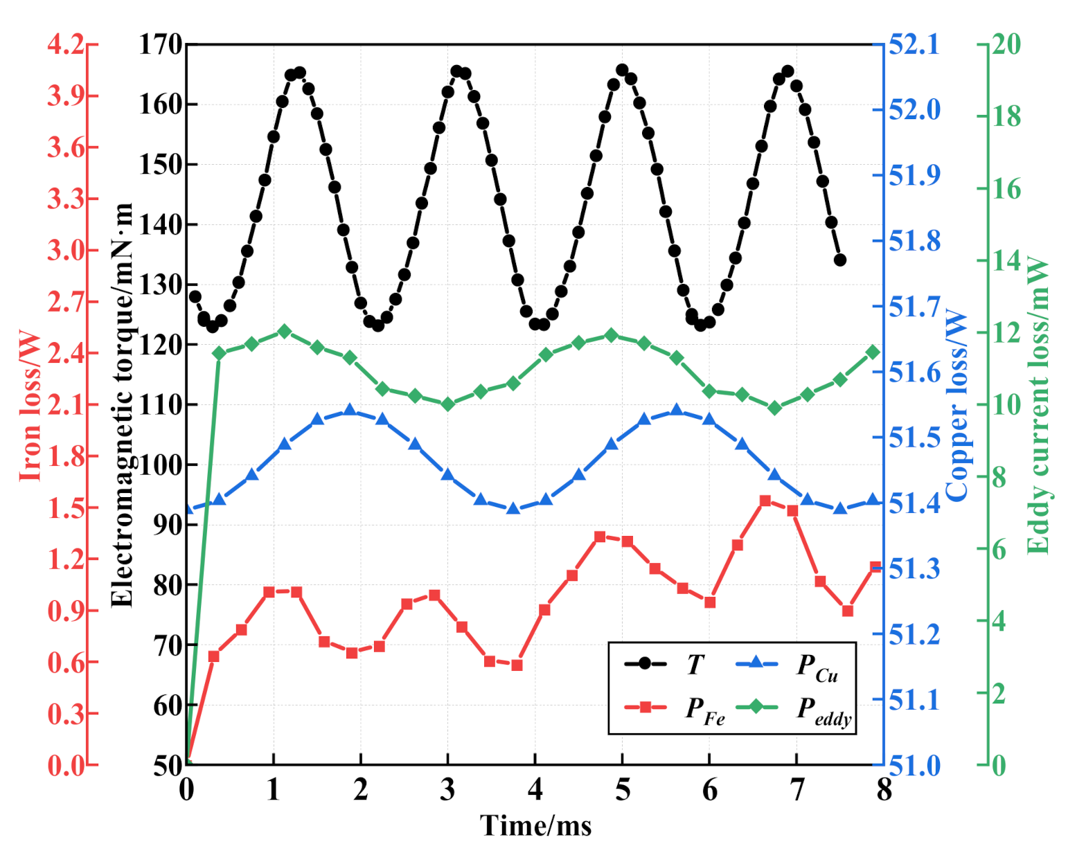
The transient simulation of the BPMSM model is carried out with a rated current flowing through the torque windings. The rotor runs at the rated speed. One cycle is determined in order to obtain the electromagnetic torque of the motor, as shown in Figure 4. Due to the cogging effect, the electromagnetic torque (T) fluctuates. The fitted value of T is 143.07 mM·m. Since the electromagnetic torque represents the output power of the BPMSM, it is selected as the optimized performance.
C.
Motor Efficiency
Motor power losses mainly include the stator iron-core loss (iron loss, PFe), the winding loss (copper loss, PCu), the permanent magnet eddy current loss (Peddy), and the mechanical loss (Pfw). The motor efficiency is calculated according to:
η = P o u t P i n = P o u t P o u t + P F e + P C u + P f w + P e d d y × 100 %
Since the BPMSM has no mechanical bearings, the mechanical loss (Pfw) is out of consideration. The BPMSM model is utilized to determine the motor loss at a full load and rated speed, and the results are shown in Figure 4.
According to Figure 4, PFe and PCu are calculated to be 1.26 W and 51.46 W. The value of Peddy is 10.6 mW, which is too small to consider. The initial motor efficiency (η) is 69.45% according to (3). To improve the efficiency of the BPMSM, PFe and PCu are selected as the optimized performance.

3.2. Sensitivity Analysis of Structural Parameters

Combining the selected BPMSM characteristics and the structural parameters to be optimized, we define the sensitivity (f) to quantify the effects of the structural parameters. A larger f means that the optimized performance is more sensitive to the structural parameters. The sensitivity f is calculated as follows:
f = y j o y j / y j x i o x i / x i
where yj and yjo is the jth performance, before and after optimization, respectively; and xi and xio is the ith structural parameter, before and after optimization, respectively.
According to electromechanics, the length of air gap δ0 is defined as the difference between the radius of the armature and the outer radius of the rotor:
δ 0 = D 2 r
Due to the coupling geometrical relationship between the optimized mechanical structural parameters, when a single structural parameter changes, other structural parameters will change accordingly. The change principle of the BPMSM structural parameters is defined as follows:
-
When bt, ht, r3, N1, and N2 change individually, all other parameters remain unchanged;
-
When r, δ0, and h change individually, r4, d2, and ht will change accordingly.
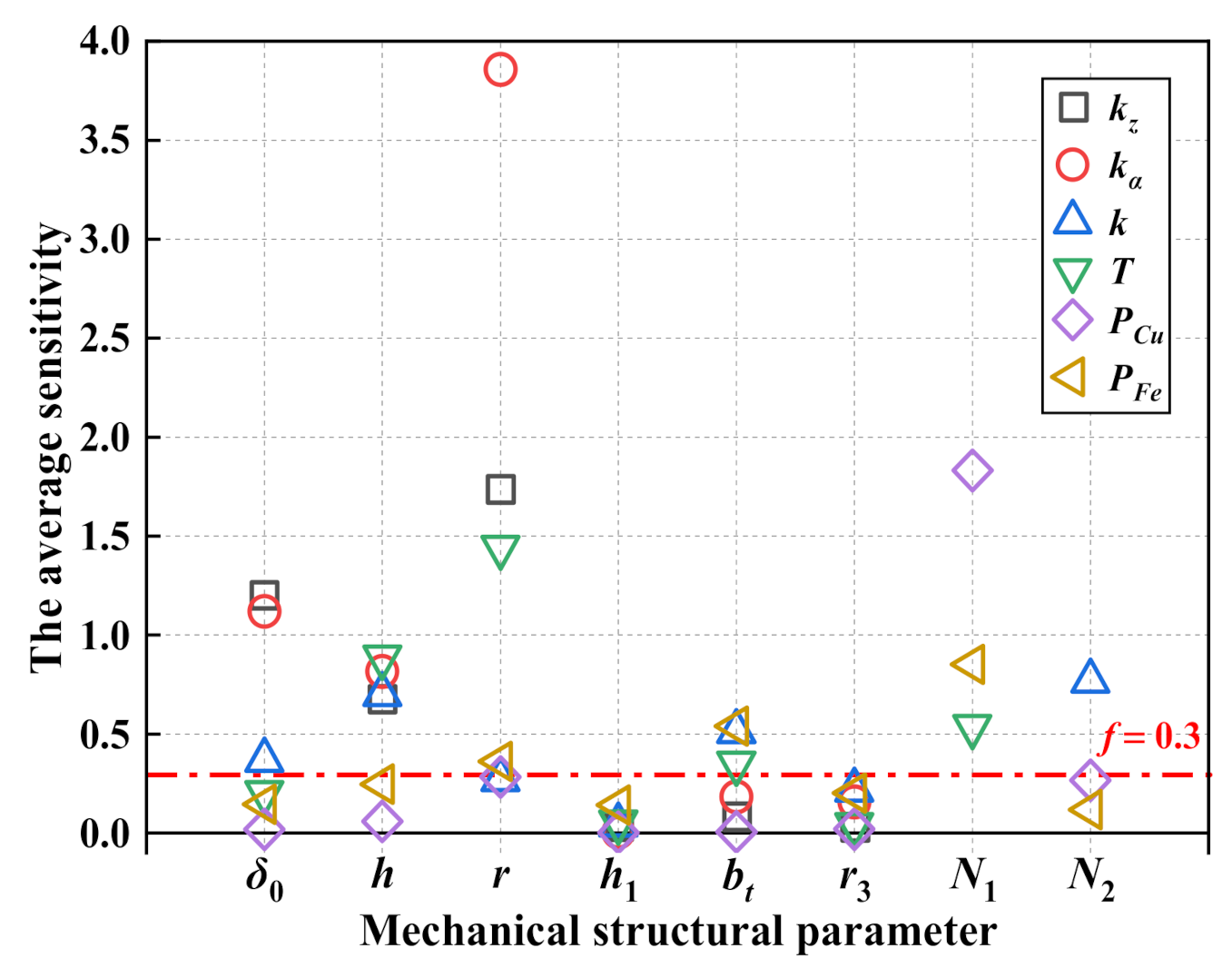
According to the above principle, the univariate simulation for the influence study of r, δ0, h, h1, bt, r3, N1, N2 to kz, kα, k, T, PCu, and PFe is carried out. For each condition of the structural parameters to meet a specified optimized performance, five groups of simulation are performed. The average sensitivity of the individual structural parameters to a specified optimized performance is determined and shown in Figure 5.
The purpose of sensitivity analyses is to screen out structural parameters with a greater impact on the overall performance. According to Figure 5, the sensitivity of different structural parameters to a specified optimized performance are concentrated as values smaller than 0.3. A larger f means that the optimized performance is more sensitive to the structural parameters. To reflect the influence of structural parameters on optimized performance with centralized characteristics, we define the threshold of 0.3 as the dominant index for sensitivity evaluations. The sensitivity evaluation index of structural parameters of BPMSM performance is shown in Table 2 using the + symbol. It can be seen from Table 2 that h and r appear five times with the highest frequency, δ0 and N1 appear three times, bt and N2 appear twice, and the others did not appear. Thus, δ0, h, r, N1, and N2 are selected as the BPMSM mechanical structural parameters.

4. Multi-Structural Optimization of BPMSM

4.1. Assess of Structural Parameter Sample Space

Considering that the multi-parameter optimization process may fail to find a global result under long solution times with arbitrary searching ranges, a sample space for the chosen structural parameters needs to be established prior to multi-parameter optimization. To make BPMSMs meet working requirements, it is necessary to keep the back electromotive force (EMF) from exceeding the rated voltage at the rated speed. When δ0 = 3 mm, r = 15.5 mm, h = 8 mm, and N1 = 180, the back EMF reaches 21.26 V, as shown in Figure 6. The interval of δ0, r, h, N1, and N2 are comprehensively set as [3,4], [14.5, 15.5], [6,8], [120,180], and [360,640].
Since the optimized performance involves kz, kα, k, T, PCu, and PFe, the sample space composed of structural parameters (δ0, r, h, N1, and N2) include 3125 samples, with each structural parameter occupying five different value levels. This will require a tremendous amount of computing power. Orthogonal experimental design refers to an experimental design method that studies multiple factors and multiple levels. According to orthogonality, some representative points can be selected from the overall test for testing. These representative points are uniformly dispersed, neat, and comparable. Thus, to extract the representative sample data, the orthogonal test method is first carried out. According to the number of factors (5) and levels (5), the ordinary orthogonal table L25(55) [26] is taken as representative of the point selection. The corresponding levels of each factor are shown in Table 3.

4.2. Single Performance Regression Model

Based on the gradient descent method, a linear regression model is determined for the mathematical expression of each optimized performance. The definition of evaluation coefficient R2 is expressed as follows:
R 2 = 1 - R S S T S S = 1 i = 1 N y i y ^ i 2 i = 1 N y i y ¯ 2
y ¯ = 1 m i = 1 m y i
where m is the number of runs; RSS is the sum of the square of all sample data errors, which is m times the mean square error (MSE); TSS is the difference between the sample data and the mean, which is m times the variance. Ideally, the predicted value of the sample data is the same as the true value, that is, RSS is 0 and R2 is 1.
The larger the R2 is, the better the BPMSM fitting performance is. The evaluation coefficient (R2) of the second-order and third-order regression models are determined individually. The R2 with the second-order regression model is 0.99 for all optimized performances. Based on the third-order regression model, the evaluation coefficient (R2) is 0.99, 0.99, 1, 1, 1, and 1 for kα, kz, PFe, PCu, k, and T, respectively. Therefore, the third-order regression model is utilized for subsequent structural parameter optimization.
To evaluate the accuracy of the formed third-order regression model, another 10 sets of data points are taken as testing samples. The percentage of the difference between the computed result based on the proposed virtual prototype and the fitting results based on the third-order regression model, is taken as the rationality evaluation index of the test point selection, which is defined as follows:
Δ = y i ro y i so / y i so × 100 %
where yiso is the optimized performance calculated using the virtual prototype and yiro is the optimized performance calculated using the regression model.
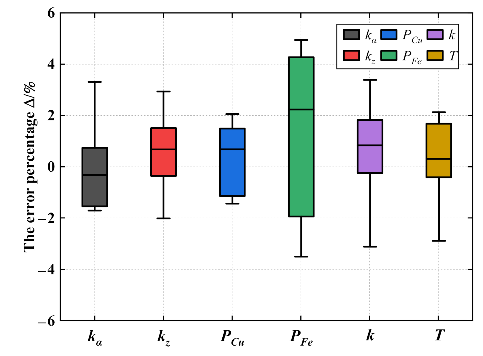
As shown in Figure 7, the absolute value of error percentage ∆ is less than 5%, indicating that the constructed third-order regression model fits well with the simulation results. The regression model is fitted based on the sample points selected by the orthogonal test, indicating the feasibility of the orthogonal test.

4.3. Dimensionless Multi-Structural Optimization Model

To compare the different optimized performances of different units, it is necessary to standardize the raw data and transform them into dimensionless values. Normalization is a typical process of data standardization. From the selection of the BPMSM performance in Section 3, we can determine that kz, kα, k, and T are benefit-based performances, but PCu and PFe are cost-based performances. Thus, the performance min–max normalizations can be defined as follows:
Benefit-based   performance :   x i j = x i j m i n x 1 j , x n j m a x x 1 j , , x n j m i n x 1 j , x n j
Cos t - based   performance :   x i j = m a x x 1 j , x n j x i j m a x x 1 j , , x n j m i n x 1 j , x n j
where xij is the parameter of the jth optimized performance of the ith test scheme in the sample dataset.
By using the linear weighted method to combine the regression model, a dimensionless multi-objective optimization function can be expressed as follows:
f o p t = m a x ( ω 1 x i 1 + ω 2 x i 2 + ω 3 x i 3 + ω 4 x i 4 + ω 5 x i 5 + ω 6 x i 6 )
where ωi (i = 1, …,6) is the weight coefficient of the ith regression model.
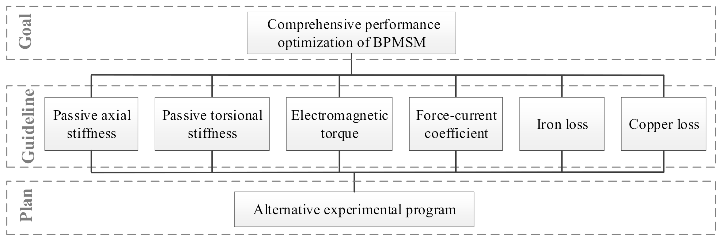
In this paper, the analytic hierarchy process (AHP) is utilized to determine the weight of each optimized performance in the multi-structural optimization function. The process of AHP is shown in Figure 8.
When using AHP to determine the weights, the importance degrees of the optimized performance need to be derived using the pairwise comparison method, and then a judgment matrix is constructed; PCu is large, but PFe is small. To improve the efficiency of the motor, PCu and T are selected as the most important optimized performances. To achieve better controllability, k is selected as the second most important optimized performance. For better passive levitation, kz and kα are selected as the third most important optimized performances. Lastly, PFe is selected as the fourth most important optimized performance.
The corresponding weights, ω1, ω2, ω3, ω4, ω5, and ω6 of kα, kz, PFe, PCu, k, and T add up to 1. The calculation results of the weights are obtained using MATLAB, as shown in Table 4.
For multi-structural optimization of the BPMSM, certain constraints must be satisfied:
(1)
The rotor diameter-to-height ratio is an important parameter that influences the axial levitation force and tilting levitation torque. In order to achieve a larger axial levitation force and tilting levitation torque, the optimal size of the BPMSM rotor diameter-to-height ratio satisfies d h 2.5 ,   4 .
(2)
Due to the power design requirement of the BPMSM, Pe = 120 W, the electromagnetic torque needs to meet T 9550 P e n N
In summary, the dimensionless multi-structural optimization function of the BPMSM can be expressed as follows:
f o p t = max ( ω 1 x i 1 + ω 2 x i 2 + ω 3 x i 3 + ω 4 x i 4 + ω 5 x i 5 + ω 6 x i 6 ) d / h = 2.5 ~ 4 T 143   mN m

4.4. Multi-Structural Optimization of BPMSM by GA

To solve the multi-input and multi-output optimization problem in (12), a GA is utilized to simultaneously determine kα, kz, PFe, PCu, k, and T. According to the dimensionless multi-structural optimization function constructed, the fitness is calculated out using a GA based in MATLAB 9.0. Since the initial population selection of the GA is random, to ensure the reliability of the optimization results, 180 sets of experimental data are analyzed using the statistical method for each condition. The structural parameter optimization results are calculated under different weights, as shown in Table 5.
From Table 5, group F of the mechanical structural parameters with the smallest fitness is selected as the optimal structural parameters. Finally, the mechanical structural parameters δ0 = 3.09 mm, h = 8 mm, r = 15.33 mm, N1 = 146, and N2 = 640 are determined. The iteration stops at the 134th step, reaching the minimum value. The optimization results of group F are selected as the optimal mechanical structural parameters. Since each torque winding has two coils per phase, N1 must be an even number. The optimal mechanical structural parameters are substituted into the finite element model, and BPMSM performance are determined again. The dominant BPMSM performances, before and after optimization, are compared in Table 6. The comparison results show that comprehensive performance of the optimized BPMSM has been significantly improved. Specifically, the passive axial stiffness, passive tilting stiffness, force-current coefficient, and motor efficiency increased by 56.4%, 71.3%, 19.6%, and 8.7%, respectively.

5. Conclusions

As a preliminary study for BPMSM development, this paper provides an effective means for BPMSM mechanical structure optimization by developing a virtual prototype based in Ansoft Maxwell. Using the sensitivity evaluation process, the candidate mechanical structural parameters for specific performances are determined. Then, orthogonal tests are performed to determine the dominant mechanical structural parameters to be optimized utilizing simulated sample datasets. The optimization model for the BPMSM mechanical structure is developed by using regression model and solved with a GA. The simulation results show that the performance of the optimized BPMSM has been comprehensively improved. To be specific, the passive axial stiffness, passive tilting stiffness, force-current coefficient, and motor efficiency increased by 56.4%, 71.3%, 19.6%, and 8.7%, respectively. The results verify the correctness and rationality of the optimization method, which can provide a novel method for the structural optimization of BPMSMs.

Author Contributions

Conceptualization, H.S., L.H. and L.Y.; methodology, Y.Y.; software, F.B.; validation, Y.Y. and F.B.; writing—original draft preparation, H.S. and F.B.; writing—review and editing, H.S.; supervision, B.L. and G.C.; project administration, P.Y.; funding acquisition, G.C. All authors have read and agreed to the published version of the manuscript.

Funding

This research was funded by the National Key Research and Development Program of China, grant number 2017YFB1104600 and the National Natural Science Foundation of China, grant numbers 51605291 and 51905383.

Institutional Review Board Statement

Not applicable.

Informed Consent Statement

Not applicable.

Acknowledgments

Thanks to Yifang Zhang for helpful discussions.

Conflicts of Interest

The authors declare no conflict of interest.

References

  1. Silber, S.; Amrhein, W.; Bösch, P.; Schöb, R.; Barletta, N. Design aspects of bearingless slice motors. IEEE/ASME Trans. Mechatron. 1995, 10, 611–617. [Google Scholar] [CrossRef]
  2. Nussbaumer, T.; Karutz, P.; Zurcher, F. Magnetically levitated slice motors—An overview. IEEE Trans. Ind. Appl. 2011, 47, 754–766. [Google Scholar] [CrossRef]
  3. Sun, X.D.; Chen, L.; Yang, Z.B. Overview of bearingless permanent-magnet synchronous motors. IEEE Trans. Ind. Electron. 2013, 60, 5528–5538. [Google Scholar] [CrossRef]
  4. Zhu, Z.Q.; Pang, Y.; Howe, D.; Iwasaki, S.; Deodhar, R.; Pride, A. Analysis of electromagnetic performance of flux-switching permanent-magnet machines by nonlinear adaptive lumped parameter magnetic circuit model. IEEE Trans. Magn. 2005, 41, 4277–4287. [Google Scholar] [CrossRef]
  5. Gruber, W.; Amrhein, W.; Haslmayr, M. Bearingless segment motor with five stator elements—Design and optimization. IEEE Trans. Ind. Appl. 2009, 45, 1301–1308. [Google Scholar] [CrossRef]
  6. Reichert, T.; Nussbaumer, T.; Kolar, J.W. Novel bearingless brushless motor in exterior rotor construction for stirred bioreactors. In Proceedings of the IET Conference on Power Electronics, Machines and Drives, Brighton, UK, 19–21 April 2010; pp. 1–6. [Google Scholar]
  7. Gruber, W.; Briewasser, W.; Amrhein, W. Novel bearingless slice motor design with four concentrated coils featuring a unique operational behavior. In Proceedings of the 14th European Conference on Power Electronics and Applications, Birmingham, UK, 30 August 2011; pp. 1–10. [Google Scholar]
  8. Zürcher, F.; Nussbaumer, T.; Gruber, W.; Kolar, J.W. Design and development of a 26-pole and 24-slot bearingless motor. IEEE Trans. Magn. 2009, 45, 4594–4597. [Google Scholar] [CrossRef]
  9. Mitterhofer, H.; Mrak, B.; Gruber, W. Comparison of high-speed bearingless drive topologies with combined windings. IEEE Trans. Ind. Appl. 2015, 51, 2116–2122. [Google Scholar] [CrossRef]
  10. Gruber, W.; Nussbaumer, T.; Gruber, H.; Amrhein, W. Wide air gap and large-scale bearingless segment motor with six stator elements. IEEE Trans. Magn. 2010, 46, 2438–2441. [Google Scholar] [CrossRef]
  11. Sugimoto, H.; Uemura, Y.; Chiba, A.; Rahman, M.A. Design of homopolar consequent-pole bearingless motor with wide magnetic gap. IEEE Trans. Magn. 2013, 49, 2315–2318. [Google Scholar] [CrossRef]
  12. Bramerdorfer, G.; Jungmayr, G.; Amrhein, W.; Gruber, W.; Marth, E.; Reisinger, M. Bearingless segment motor with halbach magnet. In Proceedings of the 2010 International Symposium on Power Electronics, Electrical Drives, Automation and Motion, Pisa, Italy, 14–16 June 2010; pp. 1466–1471. [Google Scholar]
  13. Noh, M.; Trumper, D.L. Homopolar bearingless slice motor with flux-biasing halbach arrays. IEEE Trans. Ind. Electron. 2020, 67, 7757–7766. [Google Scholar] [CrossRef]
  14. Zhang, S.R.; Luo, F.L. Direct control of radial displacement for bearingless permanent-magnet-type synchronous motors. IEEE Trans. Ind. Electron. 2009, 56, 542–552. [Google Scholar] [CrossRef]
  15. Qiu, Z.J.; Deng, Z.Q.; Zhang, Y.J. Direct levitation force control of a consequent-pole permanent magnet bearingless motor. Trans. CES 2011, 26, 94–99. [Google Scholar]
  16. Zhu, S.M.; Zhu, H.Q. Suspension force control of bearingless permanent magnet slice motor based on flux linkage identification. ISA Trans. 2015, 57, 322–328. [Google Scholar] [CrossRef] [PubMed]
  17. Zhu, H.Q.; Zhu, S.M. Study on radial suspension forces of bearingless permanent magnet slice motor based on accurate inductance model. J. Microw. Optoelectron. Electromagn. Appl. 2014, 13, 240–253. [Google Scholar] [CrossRef] [Green Version]
  18. Zhang, T.; Ni, W.; Wang, X.H.; Zhang, C.; Jia, H.Y. Optimal design on bearingless permanent magnet synchronous motor to decrease losses and torque ripple. Sens. Transducers 2014, 182, 138–145. [Google Scholar]
  19. Sugimoto, H.; Miyoshi, M.; Chiba, A. Axial vibration suppression by field flux regulation in two-axis actively positioned permanent magnet bearingless motors with axial position estimation. IEEE Trans. Ind. Appl. 2018, 54, 1264–1272. [Google Scholar] [CrossRef]
  20. Zhang, W.; Zhu, H.Q.; Xu, Y.; Wu, M.Y. Direct control of bearingless permanent magnet slice motor based on active disturbance rejection control. IEEE Trans. Appl. Supercond. 2020, 30, 205–209. [Google Scholar] [CrossRef]
  21. Noh, M.; Gruber, W.; Trumper, D.L. Hysteresis bearingless slice motors with homopolar flux-biasing. IEEE/ASME Trans. Mechatron. 2017, 22, 2308–2318. [Google Scholar] [CrossRef] [Green Version]
  22. Ding, H.F.; Zhu, H.Q.; Hua, Y.Z. Optimization design of bearingless synchronous reluctance motor. IEEE Trans. Appl. Supercond. 2018, 28, 905–909. [Google Scholar] [CrossRef]
  23. Dini, P.; Saponara, S. Cogging torque reduction in brushless motors by a nonlinear control technique. Energies 2019, 12, 2224. [Google Scholar] [CrossRef] [Green Version]
  24. Dini, P.; Saponara, S. Design of an observer-based architecture and non-linear control algorithm for cogging torque reduction in synchronous motors. Energies 2020, 13, 2077. [Google Scholar] [CrossRef]
  25. Xia, K.; Ye, Y.H.; Ni, J.W.; Wang, Y.M.; Xu, P. Model predictive control method of torque ripple reduction for BLDC motor. IEEE Trans. Magn. 2019, 56, 1–6. [Google Scholar] [CrossRef]
  26. Genichi, T. Appendix A: Orthogonal Arrays and Linear Graphs: Tools for Quality Engineering; John Wiley & Sons, Inc.: Hoboken, NJ, USA, 2007; p. 1591. ISBN 9780470258354. [Google Scholar]
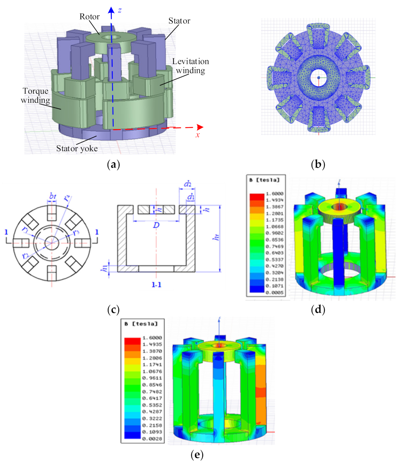
Figure 1. The structure diagram of the BPMSM. (a) The virtual prototype of the BPMSM developed in Ansoft Maxwell; (b) the meshing of the BPMSM finite element model on the xoy-plane; (c) mechanical structural parameters; (d) no-load magnetic density cloud map; and (e) magnetic density cloud map with 1 A current passing through the suspension force winding.
Applsci 11 04740 g001
Figure 2. Optimization flowchart.
Applsci 11 04740 g002
Figure 3. Linear fitting of BPMSM performance. (a) Linear fitting of axial levitation force, tilting levitation torque, and radial levitation force; and (b) relative fitting error of Fz, Tb, and Fr.
Applsci 11 04740 g003
Figure 4. The electromagnetic torque and motor losses.
Applsci 11 04740 g004
Figure 5. Sensitivity of different structural parameters to specified optimized performance.
Applsci 11 04740 g005
Figure 6. The largest back EMF in the structural parameter interval.
Applsci 11 04740 g006
Figure 7. The error percentage of the optimized performance of the test samples.
Applsci 11 04740 g007
Figure 8. The AHP flowchart.
Applsci 11 04740 g008
Table 1. Mechanical structural parameters of BPMSM.
DescriptionSymbolValue
Pole number of torque windingP11
Pole number of levitation windingP22
Outer radius of rotorr114.5 mm
Inner radius of rotorr25.5 mm
Turn number of torque coilN1160
Turn number of levitation coilN2520
Height of yokeh15.25 mm
Length of air gapδ03.75 mm
Thickness of rotorh7 mm
Diameter of armatureD36.5 mm
Inner radius of stator yoker314 mm
Outer radius of stator yoker430.75 mm
Height of stator toothht54.26 mm
Width of stator toothbt7 mm
Table 2. Sensitivity evaluation index.
BPMSM Performanceδ0hrbth1r3N1N2
kz+++
kα+++
k++ + +
T ++ +
PCu + ++
PFe +++ +
Table 3. Factor level value.
FactorLevel 1Level 2Level 3Level 4Level 5
δ033.253.53.754
r14.514.751515.2515.5
h66.577.58
N1120134148162180
N2360440520600640
Table 4. The weight coefficients of the multi-structural optimization model.
Performance Rankω1ω2ω3ω4ω5ω6
PCu > T = k > kz = kα > PFe0.1070.1070.0640.3320.1950.195
PCu = T > k > kz = kα > PFe0.0980.0980.0590.2880.1690.288
PCu > T > k > kz = kα > PFe0.0880.0880.0540.3750.1510.244
PCu = T = k > kz = kα > PFe0.1220.1220.0690.2290.2290.229
T > PCu > k > kz = kα > PFe0.0880.0880.0540.2440.1510.375
k > T = PCu > kz = kα > PFe0.1070.1070.0640.1950.3320.195
Table 5. The structural parameter optimization results under different weights.
Groupx1x2x3x4x5fopt
A3.0615.468133.54640−0.8264
B315.58146.59640−0.8501
C315.58120360−0.8125
D3.0515.468146.89640−0.8711
E315.58158.96630.96−0.8889
F3.0915.338146.47640−0.9026
Table 6. Comparison of BPMSM performance, before and after optimization.
BPMSM PerformanceBeforeAfterImprovement/%
kz/(N/mm)2.123.315856.4
kα/(N·m/rad)0.310.53171.29
k/(N/A)2.65273.172519.6
T/(mN·m)143.08173.375221.17
η/%69758.7
Publisher’s Note: MDPI stays neutral with regard to jurisdictional claims in published maps and institutional affiliations.