
Using Fuzzy Control for Feed Rate Scheduling of Computer Numerical Control Machine Tools


Abstract
1. Introduction
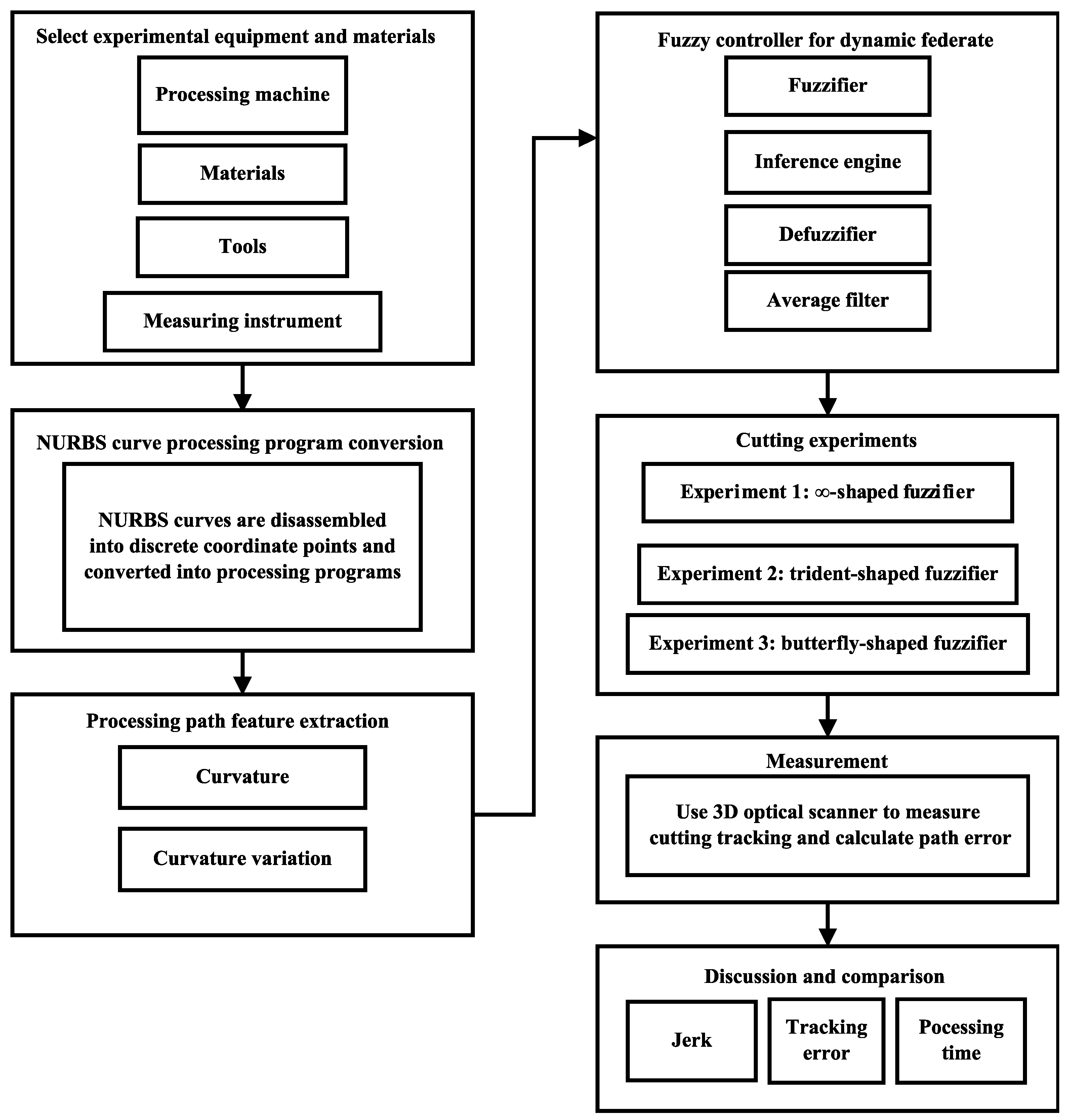
2. Materials and Methods
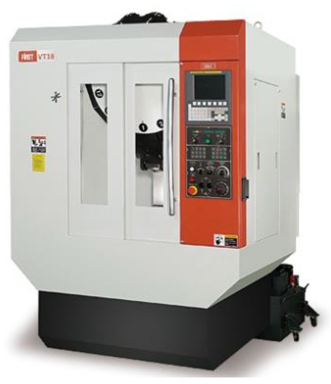
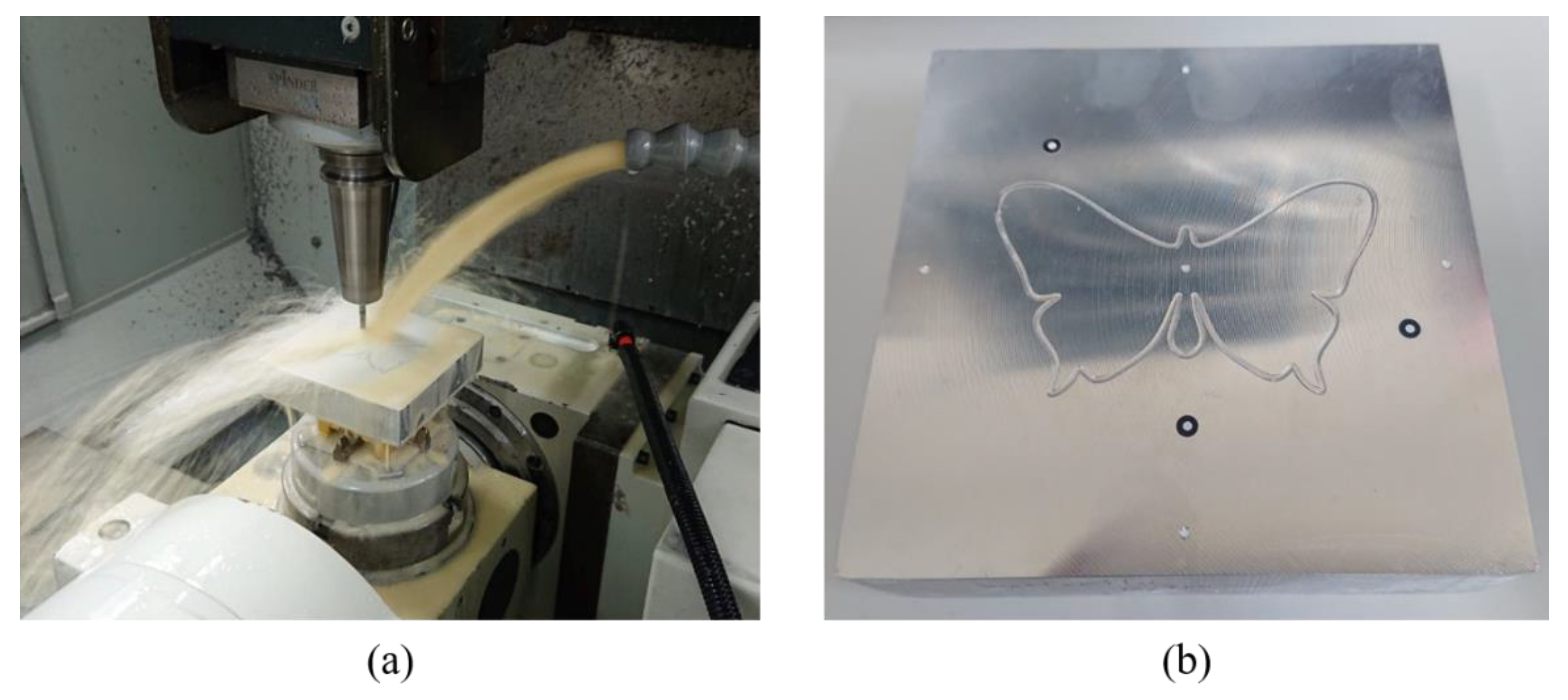
2.1. Processing Machine
2.2. Cutting Material
2.3. Cutting Tool
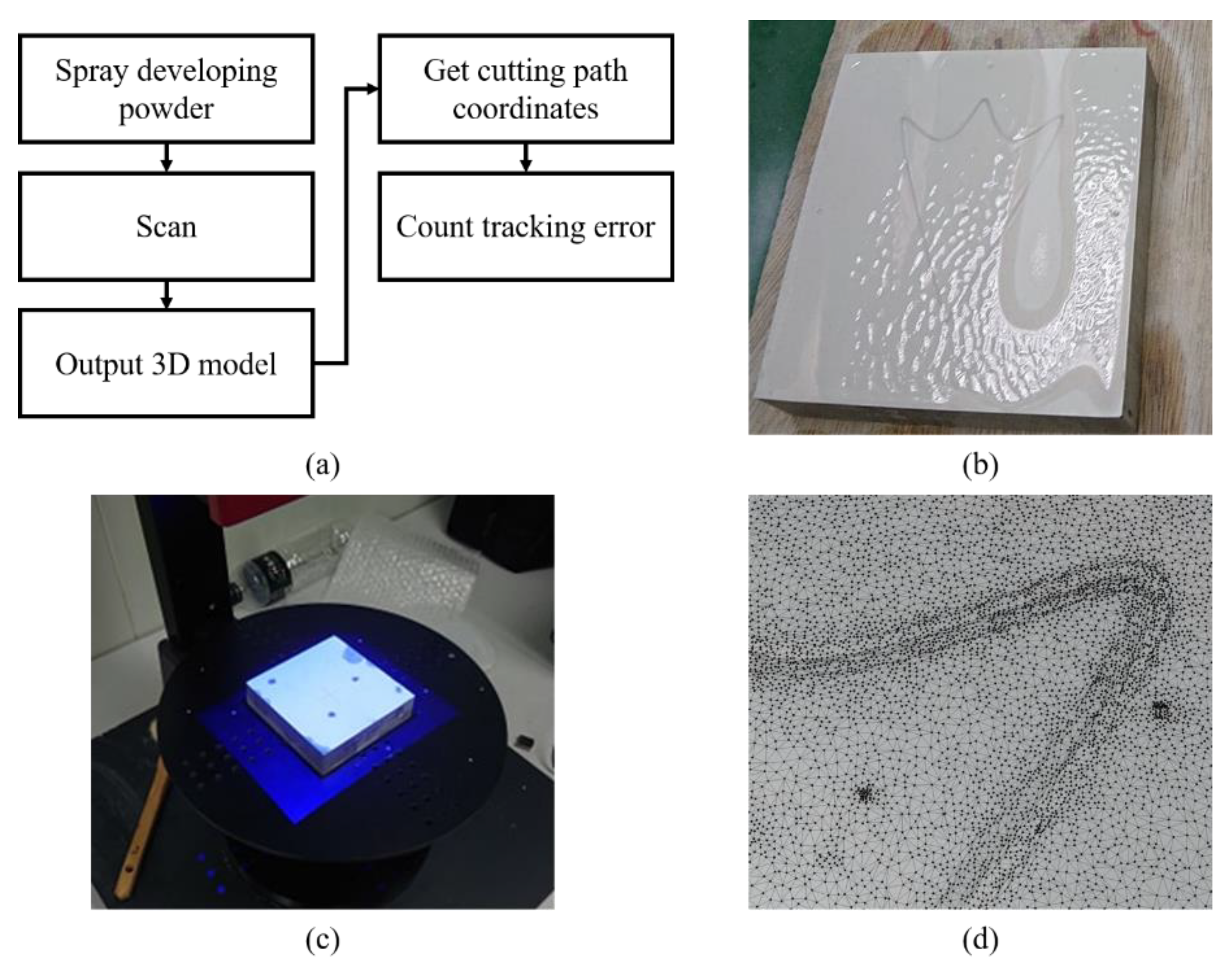
2.4. Optical Three-Dimensional (3D) Scanner
2.5. Non-Uniform Rational Basis Spline (NURBS) Curve Conversion
2.6. Machining Path Feature Extraction
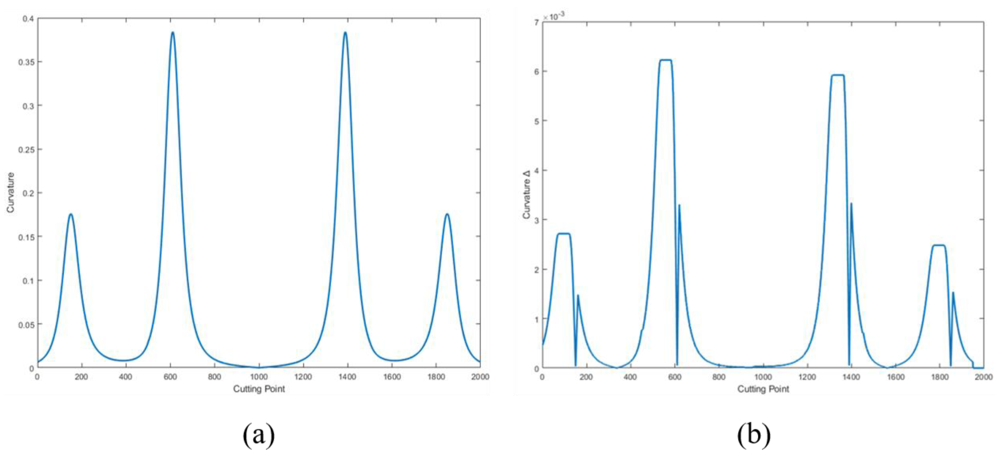
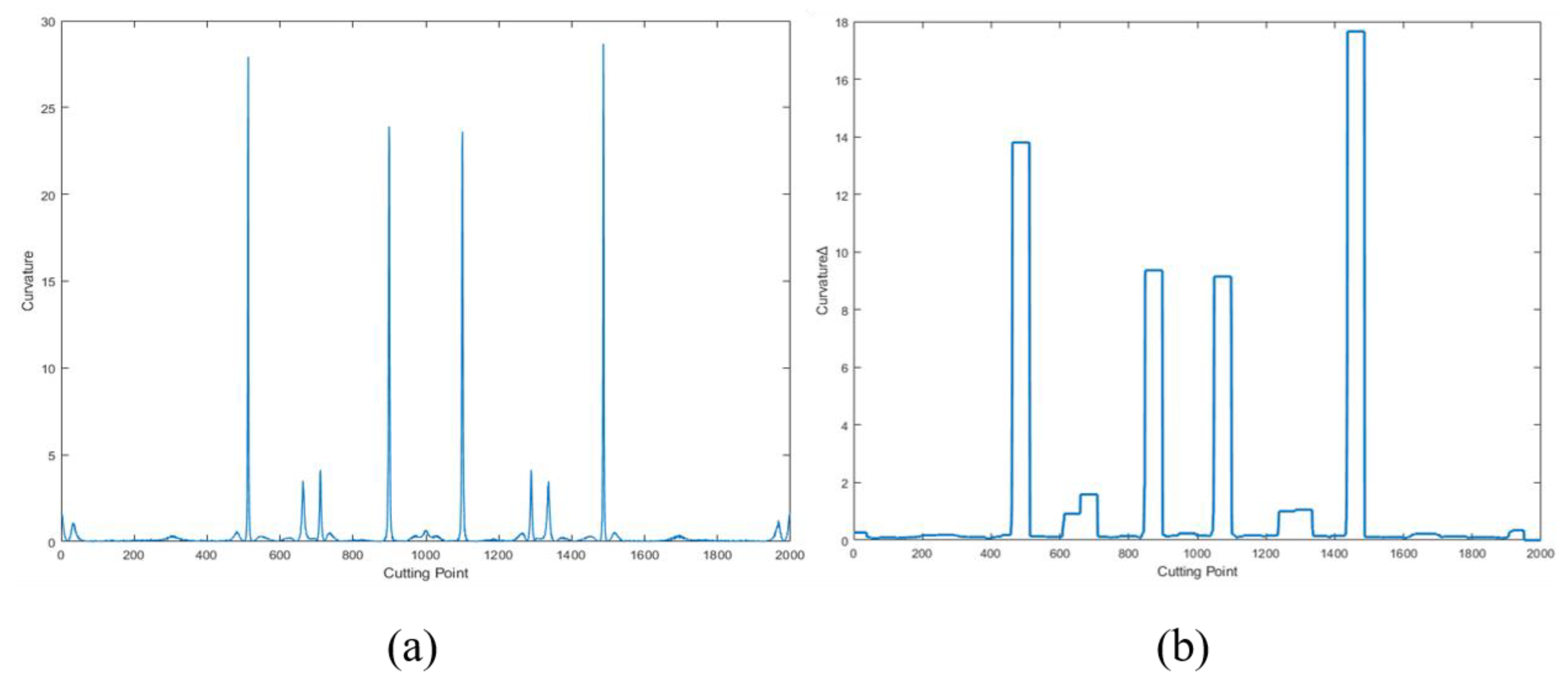
2.6.1. Curvature Calculation
2.6.2. Curvature Variation Calculation
2.7. Fuzzy Controller for Dynamic Feed Rate Scheduling
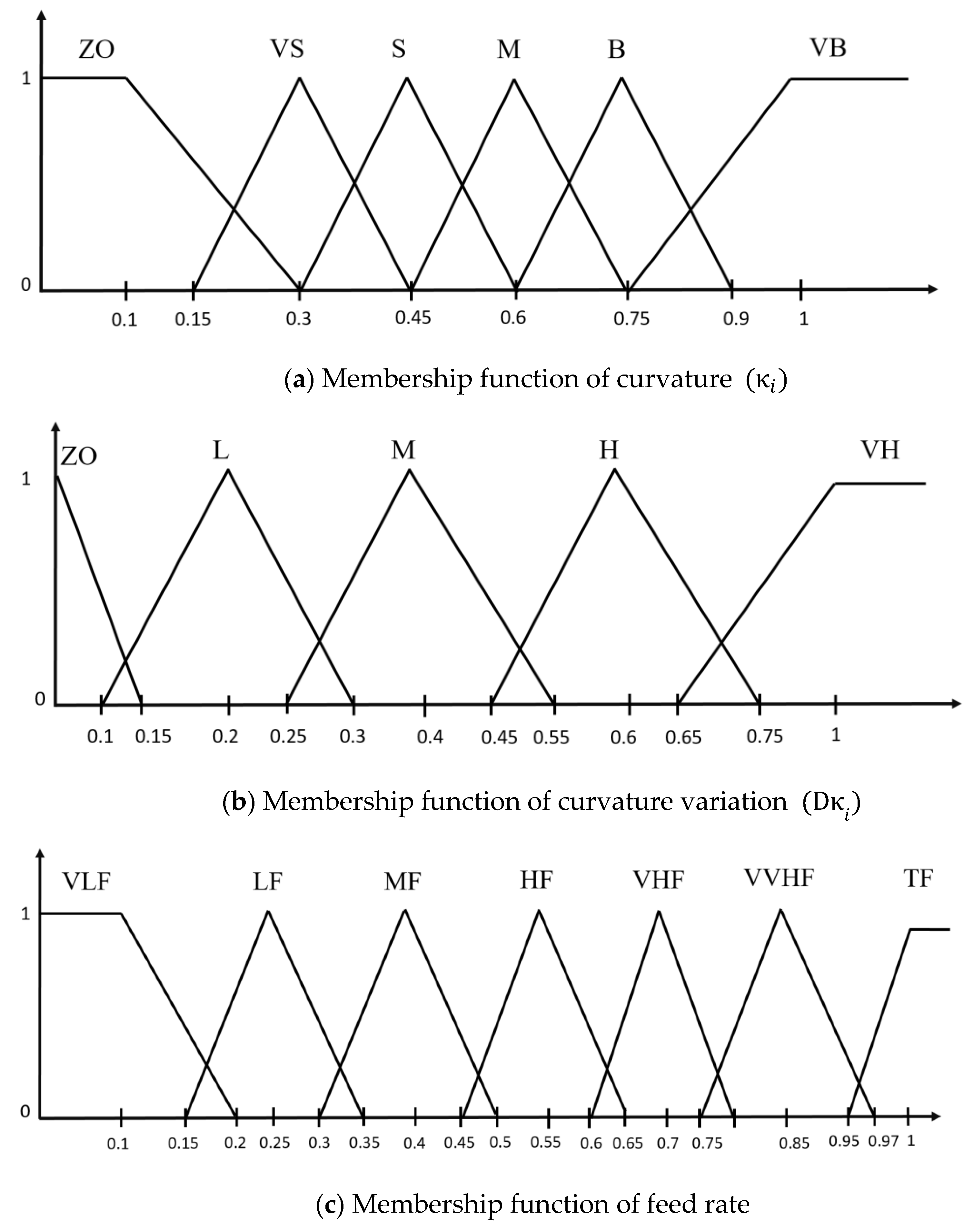
2.7.1. Fuzzy Rules
A. Fuzzification and membership function
B. Establishment of fuzzy rules
C. Fuzzy inference and defuzzification
2.7.2. Average Filter
3. Experimental Results
3.1. Optical 3D Scanner Measurement
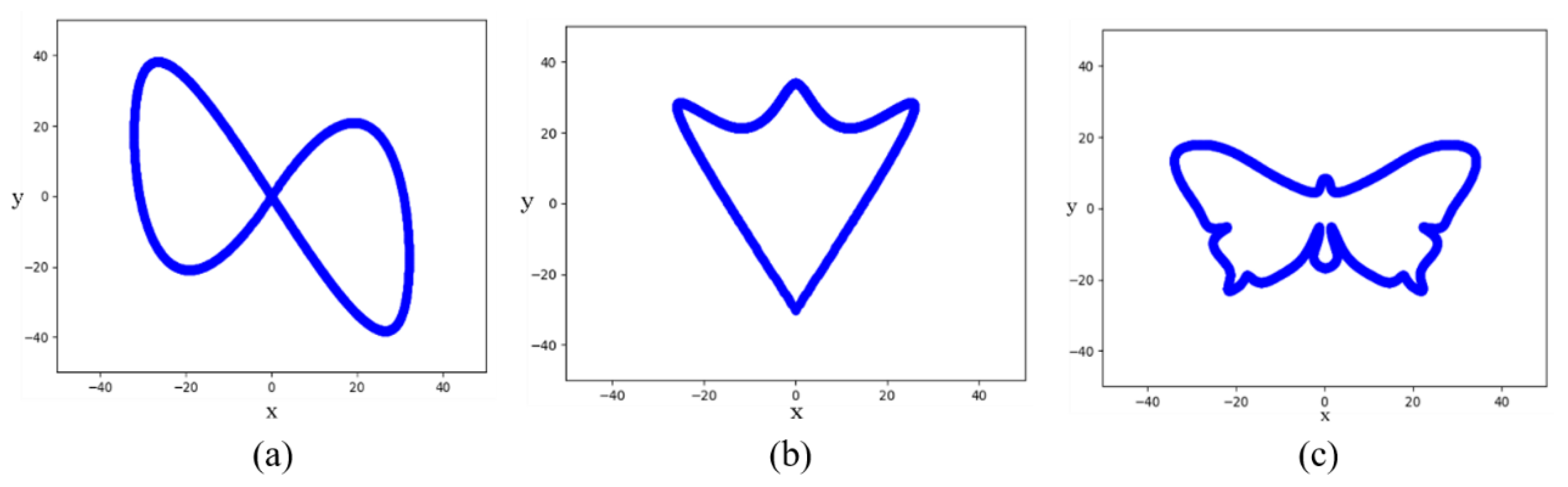
3.2. Experiment 1: Cutting ∞ Shape
3.3. Experiment 2: Cutting Trident Shape
3.4. Experiment 3: Cutting Butterfly Shape
4. Discussion
5. Conclusions
Author Contributions
Funding
Institutional Review Board Statement
Informed Consent Statement
Data Availability Statement
Acknowledgments
Conflicts of Interest
References
- Saini, S.K.; Pradhan, S.K. Optimization of multi-objective response during CNC turning using Taguchi-fuzzy application. Procedia Eng. 2014, 97, 141–149. [Google Scholar] [CrossRef]
- Gupta, A.; Singh, H.; Aggarwal, A. Taguchi-fuzzy multi output optimization (MOO) in high speed CNC turning of AISI P-20 tool steel. Expert Syst. Appl. 2011, 38, 6822–6828. [Google Scholar] [CrossRef]
- Ulsoy, A.G.; Koren, Y. Control of machining processes. ASME J. Dyn. Syst. Meas. Control. 1993, 115, 301–308. [Google Scholar] [CrossRef]
- Wang, L.; Yuan, X.; Si, H.; Duan, F. Feedrate scheduling method for constant peak cutting force in five-axis flank milling process. Chin. J. Aeronaut. 2020, 33, 2055–2069. [Google Scholar] [CrossRef]
- Kim, S.-J.; Lee, H.-U.; Cho, D.-W. Feedrate scheduling for indexable end milling process based on an improved cutting force model. Int. J. Mach. Tools Manuf. 2006, 46, 1589–1597. [Google Scholar] [CrossRef]
- Lee, H.-U.; Cho, D.-W. Development of a reference cutting force model for rough milling feedrate scheduling using FEM analysis. Int. J. Mach. Tools Manuf. 2007, 47, 158–167. [Google Scholar] [CrossRef]
- He, S.; Ou, D.; Yan, C.; Lee, C.H. A chord error conforming tool path B-spline fitting method for NC machining based on energy minimization and LSPIA. J. Comput. Des. Eng. 2015, 2, 218–232. [Google Scholar] [CrossRef]
- Yeh, S.-S.; Hsu, P.-L. The speed-controlled interpolator for machining parametric curves. Comput. Aided Des. 1999, 31, 349–357. [Google Scholar] [CrossRef]
- Luan, Z.; Jiang, G.; Bai, B.; Zhang, Y.; Mei, X. A feedrate pre-schedule NURBS interpolation method for high-speed machining. In Proceedings of the IEEE ICCA 2010, Xiamen, China, 9–11 June 2010. [Google Scholar]
- Yeh, S.-S.; Hsu, P.-L. Adaptive-feedrate interpolation for parametric curves with a confined chord error. Comput. Aided Des. 2002, 34, 229–237. [Google Scholar] [CrossRef]
- Giannelli, C.; Mugnaini, D.; Sestini, A. C2 continuous time-dependent feedrate scheduling with configurable kinematic constraints. Comput. Aided Geom. Des. 2018, 63, 78–95. [Google Scholar] [CrossRef]
- Zadeh, L.-A. Fuzzy sets. Inf. Control. 1965, 8, 338–353. [Google Scholar] [CrossRef]
- Ratava, J.; Wang, M. High speed constant force milling based on fuzzy controller and BP neural network. Int. J. Adv. Manuf. Technol. 2014, 7, 143–152. [Google Scholar]
- Huang, Y.; Yuan, J. Fuzzy feed rate and cutting speed optimization in turning. Int. J. Control. Autom. 2018, 99, 2081–2092. [Google Scholar]
- Chen, Y.; Zhang, P.; Li, H.B.; Li, P.L.; Yu, Z.Q. Design of PID controller of feed servo-system based on intelligent fuzzy control. Key Eng. Mater. 2016, 639, 1728–1733. [Google Scholar] [CrossRef]
- Miao, Z.; Li, W. A fuzzy system approach of feed rate determination for CNC milling. In Proceedings of the 2009 4th IEEE Conference on Industrial Electronics and Applications, Xi’an, China, 25–27 May 2009. [Google Scholar]
- Liang, M.; Yeap, T.; Hermansyah, A.; Rahmati, S. Fuzzy control of spindle torque for industrial CNC machining. Int. J. Mach. Tools Manuf. 2003, 43, 1497–1508. [Google Scholar] [CrossRef]
- Lin, M.-T.; Tsai, M.-S.; Yau, H.-T. Development of a dynamics-based NURBS interpolator with real-time look-ahead algorithm. Int. J. Mach. Tools Manuf. 2007, 47, 2246–2262. [Google Scholar] [CrossRef]
- Lin, K.-C.; Huang, C.-H.; Tsao, Y.-M.; Wang, J.-C.; Chiu, T.-M. Error dependent variable feedrate interpolation strategy. In Proceedings of the 2010 International Symposium on Computer, Communication, Control and Automation (3CA), Tainan, Taiwan, 5–7 May 2010. [Google Scholar]
- Ni, H.; Zhang, C.; Ji, S.; Hu, T.; Chen, Q.; Liu, Y.; Wang, G. A bidirectional adaptive feedrate scheduling method of NURBS interpolation based on S-shaped ACC/DEC algorithm. IEEE Access 2018, 6, 63794–63812. [Google Scholar] [CrossRef]


| Conditions | Parameters |
|---|---|
| X-Axis | 450 mm |
| Y-Axis | 300 mm |
| Z-Axis | 270 mm |
| Table size | 500 mm × 350 mm |
| Max. spindle speed | 10,000 rpm |
| Three-axis feed rate | X/Y/Z: 48/48/36 m/min |
| Suggested drilling rate | 12 mm/min |
| Max. table loading capacity | 150 kg |
| Controller | FANUC 0i-MD |
| Young’s Modulus | Tensile Strength | Elongation at Break | Poisson’s Ratio | Brinell Scale |
|---|---|---|---|---|
| 68.9 GPa | 124–290 MPa | 12–25% | 0.33 | 30 |
| Al | Mg | Si | Fe | Cu |
|---|---|---|---|---|
| 9598 | 0.81.2 | 0.40.8 | 00.7 | 0.150.4 |
| Specification Table | Ball-Nose Cutter |
|---|---|
| Overall length (L) | 50 mm |
| Shank diameter (d) | 1.25 mm |
| Teeth number (Teeth) | 2 |
| Scanning Area | Dot Pitch | Measurement Accuracy | Max. Scanning Distance |
|---|---|---|---|
| 200 × 150 mm2 | 0.08 mm | 0.001 mm | 250 mm |
| Curvature Variation | ZO | L | M | H | VH | |
|---|---|---|---|---|---|---|
| Curvature | ||||||
| ZO | TF | TF | VVHF | VVHF | VVHF | |
| VS | VVHF | VVHF | VHF | VHF | VVHF | |
| S | VHF | HF | HF | HF | MF | |
| M | HF | HF | MF | MF | MF | |
| B | MF | LF | LF | VLF | VLF | |
| VB | VLF | VLF | VLF | VLF | VLF | |
| Max Speed (mm/min) | Tracking Error (mm) | Time (s) | ||||
|---|---|---|---|---|---|---|
| MAX | MIN | Average | Standard Deviation | |||
| Luan et al. [9] | 300 | 0.097 | 0.012 | 0.067 | 0.0887 | 62 |
| Yeh and Hsu [10] | 300 | 0.052 | 0.007 | 0.023 | 0.0157 | 122 |
| Giannelli et al. [11] | 300 | 0.012 | 0.001 | 0.005 | 0.0035 | 907 |
| Our method | 300 | 0.056 | 0.006 | 0.028 | 0.0163 | 62 |
| Max Speed (mm/min) | Tracking Error (mm) | Time (s) | ||||
|---|---|---|---|---|---|---|
| MAX | MIN | Average | Standard Deviation | |||
| Luan et al. [9] | 300 | 0.071 | 0.001 | 0.031 | 0.0194 | 46 |
| Yeh and Hsu [10] | 300 | 0.022 | ~0 | 0.008 | 0.0050 | 127 |
| Giannelli et al. [11] | 150 | 0.006 | 0.001 | 0.004 | 0.0027 | 599 |
| Our method | 300 | 0.042 | ~0 | 0.023 | 0.0120 | 45 |
| 150 | 0.022 | 0.001 | 0.012 | 0.0060 | 92 | |
| Max Speed (mm/min) | Tracking Error (mm) | Time (s) | ||||
|---|---|---|---|---|---|---|
| MAX | MIN | Average | Standard Deviation | |||
| Luan et al. [9] | 300 | 0.09 | ~0 | 0.041 | 0.0194 | 73 |
| Yeh and Hsu [10] | 185 | 0.061 | ~0 | 0.029 | 0.0130 | 120 |
| Giannelli et al. [11] | 58 | 0.028 | ~0 | 0.017 | 0.0048 | 729 |
| Our method | 300 | 0.061 | ~0 | 0.032 | 0.0124 | 67 |
| 185 | 0.042 | ~0 | 0.026 | 0.0102 | 109 | |
| 58 | 0.024 | ~0 | 0.015 | 0.0045 | 360 | |
Publisher’s Note: MDPI stays neutral with regard to jurisdictional claims in published maps and institutional affiliations. |
© 2021 by the authors. Licensee MDPI, Basel, Switzerland. This article is an open access article distributed under the terms and conditions of the Creative Commons Attribution (CC BY) license (https://creativecommons.org/licenses/by/4.0/).
Share and Cite
Lin, C.-J.; Lin, C.-H.; Wang, S.-H. Using Fuzzy Control for Feed Rate Scheduling of Computer Numerical Control Machine Tools. Appl. Sci. 2021, 11, 4701. https://doi.org/10.3390/app11104701
Lin C-J, Lin C-H, Wang S-H. Using Fuzzy Control for Feed Rate Scheduling of Computer Numerical Control Machine Tools. Applied Sciences. 2021; 11(10):4701. https://doi.org/10.3390/app11104701
Chicago/Turabian StyleLin, Cheng-Jian, Chun-Hui Lin, and Shyh-Hau Wang. 2021. "Using Fuzzy Control for Feed Rate Scheduling of Computer Numerical Control Machine Tools" Applied Sciences 11, no. 10: 4701. https://doi.org/10.3390/app11104701
APA StyleLin, C.-J., Lin, C.-H., & Wang, S.-H. (2021). Using Fuzzy Control for Feed Rate Scheduling of Computer Numerical Control Machine Tools. Applied Sciences, 11(10), 4701. https://doi.org/10.3390/app11104701