Abstract
Two numerical algorithms for solving elastoplastic problems with the finite element method are presented. The first deals with the implementation of the return mapping algorithm and is based on a fixed-point algorithm. This method rewrites the system of elastoplasticity non-linear equations in a form adapted to the fixed-point method. The second algorithm relates to the computation of the elastoplastic consistent tangent matrix using a simple finite difference scheme. A first validation is performed on a nonlinear bar problem. The results obtained show that both numerical algorithms are very efficient and yield the exact solution. The proposed algorithms are applied to a two-dimensional rockfill dam loaded in plane strain. The elastoplastic tangent matrix is calculated by using the finite difference scheme for Mohr–Coulomb’s constitutive law. The results obtained with the developed algorithms are very close to those obtained via the commercial software PLAXIS. It should be noted that the algorithm’s code, developed under the Matlab environment, offers the possibility of modeling the construction phases (i.e., building layer by layer) by activating the different layers according to the imposed loading. This algorithmic and implementation framework allows to easily integrate other laws of nonlinear behaviors, including the Hardening Soil Model.
1. Introduction
The use of numerical codes that account for plasticity is essential when designing geotechnical structures, as they are functional decision-making tools. However, the implementation of a good plasticity model requires the development of powerful algorithms to resolve the numerical difficulties arising from complex plasticity laws such as those used for soil modeling. For example, de Souza et al. [1] present several algorithms for solving plasticity problems (that are incorporated into the HYPLAS calculation code written in FORTRAN 77). The classical Newton–Raphson scheme is very often used to solve the nonlinearities of the plasticity models since it converges at the second order, but under the condition that the initial solution is close to the true solution. Its implementation requires a rewriting of the load function as a function of the plastic deformation increment. Furthermore, it should be ensured that during the iterative procedure, this plastic increment is not less than zero, which could happen for certain plasticity models. However, the Newton–Raphson scheme can be improved by using the Homotopy–Newton–CPPM or CG–Newton–CPPM algorithms proposed by Dajiang et al. [2]. Scherzinger et al. [3] proposed a line-search algorithm with the Newton–Raphson method making it possible to force the convergence when the first guessed solution is far from the sought numerical solution. Similarly, Simo and Hughes [4] described the theoretical foundations of several formulations and algorithms for plasticity based on the Newton–Raphson procedure. In particular, they show that the construction of the elastoplastic tangent matrix, which is closely related to the rate of convergence in the Finite Element Method (FEM) and guarantees the consistency of the algorithmic integration process [5], is a crucial step for the robustness of these algorithms, hence the difficulty of implementing certain constitutive laws (such as the Hardening Soil Model law [6]). However, for the perfectly plastic behavior laws, particularly Mohr–Coulomb’s law, some authors have been able to establish this matrix analytically, as with de Souza et al. [1], who determined this matrix in the principal basis before returning it to the global basis (Cartesian) using spectral projection. Indeed, the arising functions and their derivatives expressed in the global basis are complicated, and so the eigenvectors must therefore be determined numerically [7]. This difficulty can be avoided by keeping the stresses in the main base when the plasticity or failure criterion has a very simple shape compared to its formulation in the general stress space [8]. Another approach was proposed in [9], where the authors preferred to express the yield function in a non-invariant form. This enables the derivatives and the plastic matrix to be expressed in a fairly simple algebraic form. In general, great care should be taken to avoid errors in deriving the consistent elastoplastic tangent analytically, as the calculations can become very complicated. Recently, another approach for solving local constitutive equations using conic optimization is discussed [10]. This method avoids blind guessing in the search for the elastic stress tensor (trial stresses) for the constitutive scheme. Indeed, the solution of the problem can be searched as the optimal pair (isotropic and linear behavior and linear hardening) for the convex optimization problem. Moreover, this procedure also allows to lighten the construction of the tangent operator. This operator can also be decomposed into elastoplastic and elastic tangent operators [11].
Commercial finite element software systems are available to solve geotechnical problems, including PLAXIS, ZSOIL and FLAC. However, coupling them with calibration or uncertainty analysis algorithms can be difficult due to the impossibility of accessing source codes. In addition, these software packages are expensive, and academic versions often do not offer a complete library that can meet specific needs; hence the need to develop an in-house code for research purposes. Most software packages were initially designed to meet a specific purpose before being extended to other areas. For example, the PLAXIS software we use to validate our results was initially designed for the analysis of river embankments on earthen soils before being extended to most other geotechnical fields [12].
We develop a finite element code for elastoplasticity calculations with the application of the Mohr–Coulomb soil law. This law is widely used in geotechnical engineering to model the behavior of soils, particularly those of earth dams. We advocate the use of a ‘purely’ numerical strategy to compute the consistent tangent matrix. For this purpose, we evaluate a fixed point and a finite difference scheme. These schemes are simple alternatives to existing methods for solving the return mapping. The resulting finite element code offers the flexibility to integrate other much more complex constitutive laws, particularly those whose plasticity criteria evolve during loading (such as the Hardening Soil Model [6]). In addition, it can be easily coupled with parameter calibration algorithms.
2. Plasticity Formulation
2.1. Constitutive Law of Plasticity
In linear elasticity, the constitutive law is given by:
where in plane strain case, is the stress vector, the elastic strain vector and the matrix of elasticity material properties. As soon as the yield strength is exceeded during loading, and under the assumption of small strains, permanent strains (or plastic strains) occur. The strain tensor is decomposed as:
and the stress-strain relationship is written as:
This relationship can also be written in terms of tensor rates (or in incremental form linking the increments strains to those of the stresses):
with
where represents the plastic multiplier and the dots symbol means the pseudo-time derivative of the quantity.
The in-plane strain, the elasticity tensor linking stresses and strains in the principal basis are expressed as [1,13]:
where represents the elastic and shear modulus, respectively, is the fourth symmetric order identity tensor and is the second order of identity tensor.
2.2. Return Mapping Algorithm
In plasticity problems, the constitutive laws linking stresses to strains, as well as the internal hardening law or that of the plastic multiplier (Equations (4) and (5)) are given as rates and therefore depend on the loading history. Thus, all these laws will have to be integrated over time with a numerical scheme. However, there are several numerical integration methods, including implicit and explicit Euler methods and Runge–Kutta methods. The choice of one of these methods should be simple; any one of them should provide accurate and robust results. The implicit Euler method also called the return-mapping method for elastoplastic problems and is often selected because of its stability [1,4,14,15]. This integration technique was first developed by Wilkins [16] for plane strain and elastoplasticity problems for low loads. Its extension to problems of large strains has been proposed by various authors, including Nagtegaal [17] and Simo and Taylor [18]. The iterative procedure often adopted for solving the constitutive problem is the classic Newton–Raphson scheme, which proves to be an optimal choice because of its quadratic convergence rate, generally leading to very efficient procedures in terms of the number of iterations required for convergence [1]. However, before applying this procedure, it is necessary, from the consistency condition, to express an equation dependent on the incremental plastic multiplier , as presented in [1,4]. The implementation of the return mapping resolution algorithm is laborious and often analytically impossible when the yield function f is nonlinear. Therefore, we are developing a method for solving a nonlinear system based on the fixed-point algorithm. This system (Equation (7)) is generally defined by [1]:
where at time n + 1, represents the elastic strain tensor, is the elastic strain test tensor; is the internal hardening, the plasticity flux vector, is all the combined thermodynamic forces associated with , is the generalized hardening module represents the yield function and the incremental plastic multiplier.
2.2.1. Return-Mapping Scheme for the 1D Model
To illustrate the proposed approach, we consider a 1D model, where we define the yield function f as obeying the mixed hardening law:
where represents the yield strength, K the plastic modulus and α the internal hardening variable, which has the evolution equation:
and q is the back stress defined by Ziegler’s rule as:
with H representing the kinematic hardening modulus.
For a 1D problem, the return mapping algorithm is explicitly presented in the work of Simo and Hughes [4]. It is reproduced here (Algorithm 1) with a reformulation as an algebraic system (Equation (11)) in order to highlight our numerical method.
| Algorithm 1: Return-mapping algorithm for 1D. |
The analytical resolution of the system Equation (11) gives [4]:
While there are several numerical methods for solving non-linear equation systems, we chose a simple fixed-point method. This choice is motivated by the fact that it does not require the calculation of the derivatives. Integrating Equation (11) amounts to calculating the mechanical state at the instant from a given strain increment and a state at instant . The initial values for are . The iteration is stopped for a time step when is tess then a fixed threshold. Then, once is calculated it is tested on the plasticity criterion as presented in [1]. If then the predicted state is the solution of the problem. Otherwise, the predicted state is not admissible, and a plastic correction step is performed. Algorithm 2 illustrates this iterative process for the 1D model:
| Algorithm 2: Fixed point method applied to the return mapping algorithm. |
|
2.2.2. Return-Mapping Scheme for the Mohr–Coulomb (MC) Law
The MC model generally depends on two parameters: the internal friction angle of the material and the cohesion c, which can also depend on the accumulated plastic strain and its increment . It also involves the shear stress τ and normal stress . For this criterion, the plastic strain begins when the shear stress τ, as well as the normal stress become critical. These two stresses are linked by the relationship:
The plastic function f is expressed in terms of principal stresses by:
with the convention where is the j-th principal stress. The representation of its yield surface is a hexagonal pyramid whose axis is colinear to the hydrostatic pressure (Figure 1) defined by:
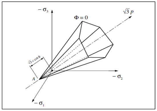
Figure 1.
Mohr–Coulomb yield surface in principal stress space [1].
The six edges of this criterion in three-dimensional space, allow it to be expressed by six load functions given by [1]:
The two-by-two intersections of these load surfaces and the vertex form singularities that pose some problems for numerical integration. Each of the six load surfaces has a plastic flow rule associated with it. In addition, the behavior of the soil during loading involves friction, and so non-associated plastic flow rules must be used to avoid excessive expansion of the material [9]. For this purpose, an expansion angle, noted as ψ, that allows the introduction of six plastic flow potentials (I = 1, …, 6) associated with each yield function . These plastic potentials are written in the same way as their respective yield surfaces (the relationships in (Equation (16)).
For example, for the yield surface we have:
The plastic flow rule is then written as:
where we recall that m is the number of active mechanisms.
Thus, with the principal stresses ordered as follows: the flow rule can be formulated in the edge space located in the same plane of the principal stresses space (the sextant plane) (Figure 2). There are then four distinct possibilities for defining the plastic flow rule:
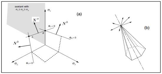
Figure 2.
The Mohr–Coulomb flow rule; (a) faces and edges, and (b) apex [1].
- ✓
- If the final stress is within the load surface, then the point is regular and a mechanism is activated, m = 1.
- ✓
- If the final stress is located on the right edge of the cone relative to the sextant plan, then the point is singular and two mechanisms are activated, m = 2.
- ✓
- If the final stress is located on the left edge of the cone relative to the sextant plan, then the point is singular and also two mechanisms are activated, m = 2.
- ✓
- If the final stress is not located inside the load surface or on an edge, then it is projected to the top of the cone, the point is singular and six mechanisms are activated, m = 6.
Figure 2 illustrates the plastic flow rule of Mohr–Coulomb’s law. Figure 2a shows how, according to the condition linking the principal stresses, the main plane and the two possible configurations for two mechanisms are activated simultaneously: the right-edge mechanism or the left-edge mechanism and the apex (Figure 2b).
- ▪
- For a single activated mechanism, the plastic flow rule is written:with the flow vector normal to the corresponding plane defined by given by:
- ▪
- For two activated mechanisms, the plastic flow rule is written:with the normal at the intersection of the two planes and or and , given by:
- ▪
- For six activated mechanisms, the plastic flow rule is written
The updated stress tensor in the return mapping algorithm is generally given by equation Equation (24). For an isotropic model, and taking into account the elastic rigidity matrix linking the principal stresses and strains given to Equation (5), Mohr–Coulomb’s constitutive law written in principal stresses is ([1,19]):
where represents the i-th volumetric component of the updated plastic flow vector, tr[ ] the trace of the second-order tensor and the j-th eigenvalue of its deviatoric projection.
From Equation (24), four return mappings of Mohr–Coulomb’s law according to the active mechanisms follow: to the smooth portion, to the right edge, to the left edge, and to the apex.
- (a)
- Return mapping to the smooth portion
For a single activated mechanism and taking into account its flow rule, the principal updated stresses give:
with the accumulated plastic strain:
By combining Equation (25a,c) we have:
The consistency condition in this case is given by:
By substituting Equation (27) in Equation (28) and after a few transformations, the analytical form of is obtained by:
with
In the case where the material properties are non-linear, we adopt a fixed-point algorithm to complete the resolution. The fixed point algorithm applied to the return mapping of the main plane mechanism (Algorithm 3) is based on the constitutive law of the activated mechanism (Equation (25)), with the initial conditions taken in the elastic domain . In this algorithm, the plastic multiplier ∆γ is obtained by substituting the principal trial stresses in the consistency equation for this activated mechanism Equation (28). Moreover, from Equation (28) we deduce .
| Algorithm 3: Fixed point algorithm applied to the main plane mechanism. |
|
- (b)
- Return mapping to the right edge
Similarly, for two mechanisms activated on the right edge, the principal updated stresses are:
with the accumulated plastic strain given by:
The combination of equations Equation (30a,c) gives:
By substitution of Equation (32) into Equation (28) and after some transformations, we obtain:
with
For the second mechanism, the consistency condition is given by:
The combination of equations Equation (30a,b) gives:
By substitution of Equation (36) into Equation (35) and after some transformations, we obtain:
From Equations (33) and (37), we can deduce the scalar form of and , defined by:
or
with
Remark 1.
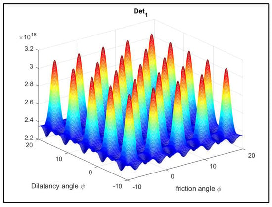
Regardless of the «physical» values taken by parameters K, G, ϕ and ψ,. (see Figure 3).

Figure 3.
Example of values for K = 1.67 × 10⁸ and G = 6.39 × 10⁵.
The fixed-point algorithm applied to the return mapping of the right edge mechanism (Algorithm 4) is based on the constitutive law given in Equation (30). Its initial conditions are also taken in the elastic domain ().
| Algorithm 4: Fixed point method applied to the right edge mechanism. |
|
- (c)
- Return mapping to the left edge
For two mechanisms activated on the left edge, principal updated stresses are given by:
Similarly, the accumulated plastic strain is given by:
The combinations of equations Equation (39a,c) gives:
By substituting Equation (41) into Equation (28) and making some transformations, we obtain:
with
For the second activated mechanism, the consistency condition is given by:
The combination of equations Equation (39a,b) gives:
By substituting Equation (45) into Equation (44) and making some transformations, we obtain:
From Equations (42) and (46), the scalar forms of and are:
or
with
Remark 2.
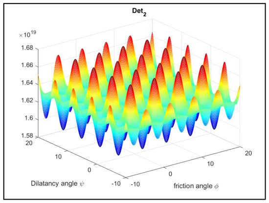
Similarly, for «physical» values of parameters K, G, ϕ and ψ,(see Figure 4).

Figure 4.
Example of values for K = 1.67 × 10⁸ and G = 6.39 × 10⁵.
The fixed-point algorithm applied to the left edge mechanism (Algorithm 5) is based on the constitutive law of the activated mechanism (Equation (39)). Its initial conditions are taken in the elastic domain ().
| Algorithm 5: Fixed point algorithm applied to the left edge mechanism. |
|
- (d)
- Return mapping to the apex
Finally, in the case of the Apex, the stress is located on the hydrostatic axis. The hydrostatic pressure is then written:
where represents the volumetric plastic strain increment and is given by:
The updated stress and the accumulated plastic strain are given by [1]:
with .
The fixed-point algorithm applied to the return mapping to the Apex mechanism (Algorithm 6) is also based on the constitutive law of the activated mechanism (Equation (48)). Its initial conditions, taken in the elastic domain, are and The volumetric plastic strain increment can still be written as a function of the hydrostatic pressure p using equations Equation (15) and Equation (48).
| Algorithm 6: Fixed point algorithm applied to the Apex mechanism. |
|
2.3. The Elastoplastic Consistent Tangent Operator
The elastoplastic consistent tangent operator is closely related to the algorithmic form for updating the stress tensor. Indeed, it is obtained by performing a linearization of the stress updating algorithm [1,4,20]. Thus, in this section, we present a numerical method using a first-order finite difference scheme for calculating this tangent operator. However, the analytical method is presented in Section 2.3.1 for 1D case and in the Appendix A for 2D case. Analytical calculation is often laborious, and sometimes even impossible to perform exactly. In the numerical approach, the return mapping algorithm is used twice. The additional numerical calculations come with more time consumption, but the complexities associated with the analytical calculations are overcome. Furthermore, the computational overload due the finite difference algorithm can be substantially reduced using parallel programing. The general expression of the consistent elastoplastic tensor is given by:
where represents the stress tensor at time .
2.3.1. 1D Illustration
Using the consistency condition , the expression of is given by:
and so, the relationship of the constitutive law linking to becomes:
We can therefore deduce the tangent modulus obtained analytically for the 1D model:
The tangent module is in general not easy to determine. Indeed, in this case, it was only made possible because of the linear shape of the yield loading function. However, if this function is non-linear, and for higher dimension problems, the calculations become tedious or even impossible and a numerical method may be necessary. Thus, at a time corresponding to the load increment and iteration k of the Newton–Raphson algorithm solving the equations of equilibrium, the elastoplastic tangent modulus is:
In the 1D case, the analytical derivation leads to Equation (54). However, this result is not general [4]. The tangent elastoplastic tensor can be obtained in the triaxial case from the yield function expressed in terms of principal stresses. It is therefore necessary to bring it back to the Cartesian basis. The following approximation for a small can be used:
where:
In Equation (57), is an appropriate small number (e.g., ) that represents the amount of perturbation. The perturbed strain is:
and the strain increment is
For a given , the value of is obtained by the return mapping method presented in Algorithm 2. The perturbed stress is calculated from the perturbed strain using the same procedure. Finally, the tangent modulus is determined by the relationship:
The illustration of this numerical method is presented in Algorithm 7.
| Algorithm 7: Numerical computation of the elastoplastic tangent modulus. |
|
2.3.2. Case of Mohr–Coulomb’s Law
The numerical method of the elastoplastic tangent matrix presented in the 1D case is generalized for the in-plane strain and for Mohr–Coulomb’s law.
The elastoplastic tangent matrix is approximated using a first order finite difference scheme for each component of:
Each component of the strain vector is thus perturbed according to the same principle stated in Section 2.3.1, and so allows an approximation of the elastoplastic tangent matrix to be calculated for each activated mechanism.
3. Numerical Study
In this section, we show the efficiency of the proposed numerical methods. For this purpose, two examples are considered. The first example concerns the solution of a bar (under a traction load) problem proposed by Kim [14]. This is a classical benchmark test for which there exists an analytical solution. Therefore, any numerical algorithm in plasticity must pass it.
The second example deals with a symmetrical rockfill dam modeled in plane strains according to Mohr–Coulomb’s law.
3.1. Example 1: Nonlinear Bar Problem
The bar considered is uniform with a cross-sectional area and a unit length . A traction force of magnitude is applied at the end of the bar (Figure 5).

Figure 5.
Nonlinear bar problem [14].
The yield strength is In the elastic region, the bar’s Young’s modulus is and in the plastic region, its plastic modulus is zero. Its yield function obeys Equation (7).
Figure 6 shows the stress-strain for a single element of the 1D bar. Ten equal load levels are applied to the bar. In the legend, Ana-NR represents the results from the analytical calculation of , Num-NR represents the numerical calculation of , and (Kim) represents the exact solution [14].
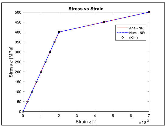
Figure 6.
Stress-strain for a single element considered for and .
The results obtained for both models and for the exact solution (Ana-NR, Num-NR and Kim) are virtually identical (Figure 6). For loads below 40 kN, all models converge (Table 1) in a single iteration (elastic domain). Above 40 kN (the plastic domain), the Ana-NR and Num-NR models converge (i.e., meet the convergence criterion which is where represents the external force, the internal force and the Euclidean norm) after at most two iterations. All the results show that the proposed numerical model for the calculation of the tangent module (Num-NR) is sufficiently accurate and efficient. In summary, the results prove that the exact solution is obtained no matter how many elements are used. The case of 10 elements is to show that the code behaves correctly for any mesh.

Table 1.
Convergence rate and number of iterations by loading: 1D case.
Figure 6 also shows that the yield strength is reached at 400 MPa, and beyond this value, the bar becomes in plastic mode. To better observe these areas, we divided the bar into ten identical elements of two nodes each. Ten successive loads in 5 kN steps were applied. The evolution of plasticity in the bar during these loads for the Num-NR model is presented in Figure 7.
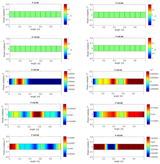
Figure 7.
Evolution of the plasticization in the bar with to the applied load.
3.2. Example 2: Rockfill Dam
To test the efficiency of the algorithm in the case of a more complex behavior, we consider an example of a rockfill dam. This rockfill dam is assumed to be dry, homogeneous and symmetrical, and subject to its own weight. This dam has a width L of 320 m, a height h equal to 100 m and a crest length of 9 m. The depth of the dam axis is assumed to be infinite, which makes it possible to carry out a study of in-plane strain. Vertical and horizontal movements are zero at the base. Hooke’s law is used in cases where the material has an elastic behavior. In the plastic case, the Mohr–Coulomb model is used in its non-associated version to avoid excessive expansion of the material [9]. The material properties correspond to those used in [21] of a rockfill dam: Young’s modulus , Poisson coefficient , density , material cohesion c = 0, internal friction angle and material dilatancy angle . We propose to compare the results obtained with our code developed in the Matlab environment and those obtained using the commercial software PLAXIS for the mesh sizes presented in Figure 8. The construction of the dam is simulated by adding successive layers, with 20 layers in total.

Figure 8.
Mesh used (a) PLAXIS: 327 triangular elements with 15 nodes and (b) Matlab: 800 quadrilateral isoparametric bilinear quadrilateral elements (40 × 20) with 4 nodes.
The vertical and horizontal displacements, as well as the principal stresses in the first and second direction for the entire domain, are presented in Figure 9. Although the comparison of isovalues for the Matlab and PLAXIS models must be done with care, the displacements and calculated main stresses show a satisfactory correspondence. Indeed, for displacements, we note a relative difference of only 2% and 0.1% respectively for the maximum values of ux and uy. For the maximum stresses, there is a relative difference of 4% and 11% for the principal stress 1 and principal stress 2, respectively.
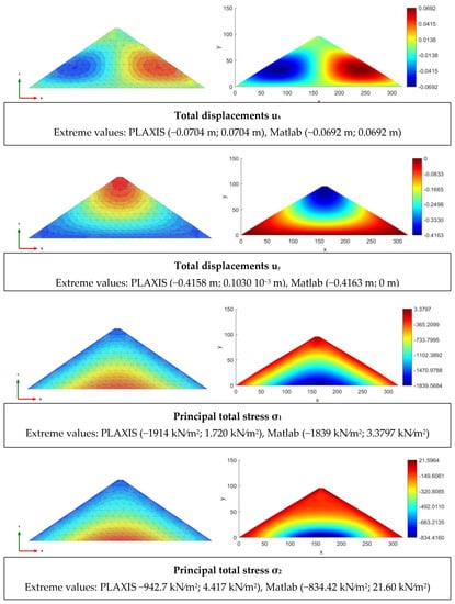
Figure 9.
Comparisons of horizontal (ux) and vertical (uy) displacements and normal stresses calculated for and .
Comparisons of the values obtained for this approach, particularly in the column and row under consideration (Figure 10), show that the vertical (uy) and horizontal (ux) displacements, as well as the normal stresses in the X and Y directions, are also in agreement with those obtained with PLAXIS (Figure 11 and Figure 12, respectively).

Figure 10.
Choice of the studied areas for the comparison of variables: (a) column considered and (b) row considered.
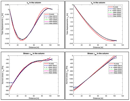
Figure 11.
Displacements and stresses in the column considered for Matlab and PLAXIS models according to mesh size.
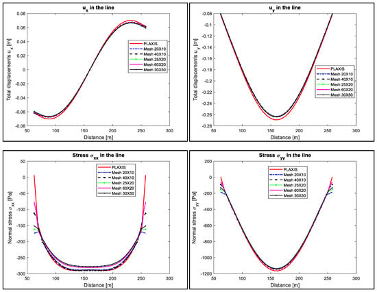
Figure 12.
Displacements and stresses in the line considered for Matlab and PLAXIS models according to mesh size.
However, some small differences are observed. On the one hand, these could be attributed to the mesh sizes and to the shape of the elements, as those developed for our Matlab code differ from those used for the commercial software PLAXIS. On the other hand, these differences may also be due to how the loading was applied. It should be noted, however, that the results are very encouraging, especially since we do not need to calculate the tangent matrix analytically with our numerical model for more complex constitutive laws.
The code developed for Matlab also offers the possibility of studying the problem layer by layer according to the imposed load, and by refining the mesh size. These loads are represented by the different layers of the domain. Table 2 shows the number of iterations and the convergence calculated according to the loading for the numerical model (i.e., the elastoplastic tangent matrix is calculated by the finite difference method). For the three meshes (20 × 10, 60 × 20 and 30 × 30), the convergence tolerance in the equilibrium iterations has been set to . The maximum number of iterations in any load step (layer) is 8.

Table 2.
Convergence rate and number of iterations by loading: 2D case.
4. Conclusions
Two methods for solving elastoplastic problems have been developed in this work. The first is related to the return-mapping scheme and is based on the fixed-point algorithm. The second is the calculation of the consistent tangent matrix and is based on finite differences. These two methods were implemented on an in-house finite element Matlab code. The algorithms were first validated by applying them to a 1D problem. The numerical results obtained during the simulations proved to be in excellent agreement with the exact solution [14]. They were then extended to the problem of a 2D dam subjected to plane strains and using Mohr–Coulomb’s law. Two numerical methods for solving the system of non-linear return-mapping equations and the calculation of the tangent elastoplastic matrix were presented. Using these approaches, a set of simulations was performed, and the results compared to those obtained using the commercial software PLAXIS. The results of the different approaches remain in agreement with those given by PLAXIS, with deviations of around 2% and 0.1% in displacements for ux and uy, and of a maximum of 11% in stresses. These results are very encouraging, especially since we do not need to analytically calculate the often-tedious tangent matrix, thereby confirming the effectiveness of the numerical models developed in this work.
Author Contributions
Conceptualization: A.S.; methodology, A.S. and G.Y.A.; software, A.S. and G.Y.A.; validation, A.S. and G.Y.A.; investigation, G.Y.A.; resources, A.S.; writing—original draft preparation, G.Y.A.; writing—review and editing, G.Y.A.; visualization, G.Y.A.; supervision, A.S.; project administration, A.S.; funding acquisition, A.S. All authors have read and agreed to the published version of the manuscript.
Funding
This research was funded by Natural Sciences and Engineering Research Council of Canada and Hydro-Québec, grant number RDCPJ470297-14.
Institutional Review Board Statement
Not applicable.
Informed Consent Statement
Not applicable.
Conflicts of Interest
The authors declare no conflict of interest.
Appendix A
For the analytical method, this matrix will first be expressed in the principal basis, as the yield functions have already been expressed. Then, by means of the chain rule derivation, it will be returned to the global basis using the DGISO2 procedure proposed by de Souza Neto et al. [1] for calculating the tensor derivative of a 2D isotropic function.
- (a)
- Main plane
By substituting Equation (29) into Equation (25), after differentiation we have:
Knowing that
and because the trial stress is assumed to be elastic, Equation (A2) becomes:
with
representing the normal vector applied to the flow potential of the main plane, and the differentiation of the consistency condition given in Equation (28) is defined by
with
representing the normal vector applied to the yield function of the main plane, so that
Finally, the consistent tangent operator in the principal basis and for the main plane obtained analytically can be written as:
- (b)
- Right edge
We replace Equation (38) in Equation (30), and then differentiate to find:
where represents the normal vector applied to the flow potential of the right edge, and
In this last relationship, we still have to express the incremental plastic multiplier as a function of the incremental plastic strain. Therefore, after differentiating the consistency conditions given in Equations (28) and (35) defined by:
with
representing the normal vector applied to the yield function of the right edge and the plastic multipliers defined by
the increment of the j principal stress is then written as:
The consistent tangent operator in the main base for the right edge obtained analytically is therefore:
- (c)
- Left edge
As before, we substitute Equation (47) into Equation (39) and then after differentiating, to obtain:
and
In addition, taking into account the differentiation of the consistency conditions given in Equations (28) and (44) and defined by
with
and plastic multipliers given as:
the increment of the main stress j is then written as:
Finally, the consistent tangent operator in the principal basis and for the left edge obtained analytically is:
- (d)
- Apex
By evaluating the pressure and strain equations Equations (15) and (50), respectively, we find:
Thus, the consistent tangent operator in the principal basis for the Apex is
Remark A1.
It should be noted that the analytical calculation of the elastoplastic tangent tensor in this case is only valid for constant parameters (without any material non-linearity as in the Duncan-Chang hyperbolic constitutive law [22] or the HS law [6]).
References
- Neto, E.A.d.; Peric, D.; Owen, D.R. Computational Methods for Plasticity: Theory and Applications; John Wiley & Sons: Hoboken, NJ, USA, 2008. [Google Scholar]
- Geng, D.; Dai, N.; Guo, P.; Zhou, S.; Di, H. Implicit numerical integration of highly nonlinear plasticity models. Comput. Geotech. 2021, 132, 103961. [Google Scholar] [CrossRef]
- Scherzinger, W.M. A return mapping algorithm for isotropic and anisotropic plasticity models using a line search method. Comput. Methods Appl. Mech. Eng. 2017, 317, 526–553. [Google Scholar] [CrossRef]
- Simo, J.; Hughes, T. Computational Inelasticity; Springer: Berlin/Heidelberg, Germany, 2006; Volume 7. [Google Scholar]
- Simo, J.C.; Taylor, R.L. Consistent tangent operators for rate-independent elastoplasticity. Comput. Methods Appl. Mech. Eng. 1985, 48, 101–118. [Google Scholar] [CrossRef]
- Schanz, T.; Vermeer, P.; Bonnier, P. The hardening soil model: Formulation and verification. In Beyond 2000 in Computational Geotechnics; Ten Years of PLAXIS International. Proceedings of the International Symposium; Routledge: London, UK, 1999; pp. 281–296. [Google Scholar]
- Meng, C.; Tang, Z.; Chen, M.; Peng, Q. Return mapping algorithm in principal space for general isotropic elastoplasticity involving multi-surface plasticity and combined isotropic-kinematic hardening within finite deformation framework. Finite Elem. Anal. Des. 2018, 150, 1–19. [Google Scholar] [CrossRef]
- Clausen, J.; Damkilde, L. An exact implementation of the Hoek–Brown criterion for elasto-plastic finite element calculations. Int. J. Rock Mech. Min. Sci. 2008, 45, 831–847. [Google Scholar] [CrossRef]
- Griffiths, D.; Willson, S. An explicit form of the plastic matrix for a Mohr–Coulomb material. Commun. Appl. Numer. Methods 1986, 2, 523–529. [Google Scholar] [CrossRef]
- Bruno, H.; Barros, G.; Menezes, I.F.; Martha, L.F. Return-mapping algorithms for associative isotropic hardening plasticity using conic optimization. Appl. Math. Model. 2020, 78, 724–748. [Google Scholar] [CrossRef]
- Čermák, M.; Sysala, S.; Valdman, J. Efficient and flexible MATLAB implementation of 2D and 3D elastoplastic problems. Appl. Math. Comput. 2019, 355, 595–614. [Google Scholar] [CrossRef]
- Brinkgreve, R.; Kumarswamy, S.; Swolfs, W.; Waterman, D.; Chesaru, A.; Bonnier, P. Plaxis 2016; PLAXIS bv: Delft, The Netherlands, 2016. [Google Scholar]
- Marc, K. Loi de Mohr-Coulomb- Code_Aster. 2016. Available online: https://www.code-aster.org/V2/doc/v13/fr/man_r/r7/r7.01.28.pdf (accessed on 1 February 2021).
- Kim, N.H. Introduction to Nonlinear Finite Element Analysis; Springer Science & Business Media: Berlin/Heidelberg, Germany, 2014. [Google Scholar]
- Simo, J.C.; Govindjee, S. Non-linear B-stability and symmetry preserving return mapping algorithms for plasticity and viscoplasticity. Int. J. Numer. Methods Eng. 1991, 31, 151–176. [Google Scholar] [CrossRef]
- Wilkins, M.L. Calculation of elastic-plastic flow. In Methods in Computational Physics; Alder, B., Fernbach, S., Roteerg, M., Eds.; Academic Press: New York, NY, USA, 1964; Volume 3, pp. 211–263. [Google Scholar]
- Nagtegaal, J.C. On the implementation of inelastic constitutive equations with special reference to large deformation problems. Comput. Methods Appl. Mech. Eng. 1982, 33, 469–484. [Google Scholar] [CrossRef]
- Simo, J.C.; Taylor, R.L. A return mapping algorithm for plane stress elastoplasticity. Int. J. Numer. Methods Eng. 1986, 22, 649–670. [Google Scholar] [CrossRef]
- Sysala, S.; Čermák, M.; Ligurský, T. Subdifferential-based implicit return-mapping operators in Mohr-Coulomb plasticity. Zamm-J. Appl. Math. Mech. /Z. Für Angew. Math. Und Mech. 2017, 97, 1502–1523. [Google Scholar] [CrossRef]
- Semenov, A.S.; Liskowsky, A.; Balke, H. Return mapping algorithms and consistent tangent operators in ferroelectroelasticity. Int. J. Numer. Methods Eng. 2010, 81, 1298–1340. [Google Scholar] [CrossRef]
- Hamed, A.A. Predictive Numerical Modeling of the Behavior of Rockfill Dams. Ph.D. Thesis, École de Technologie Supérieure, Montréal, QC, Canada, 2017. [Google Scholar]
- Ni, P.; Mei, G.; Zhao, Y.; Chen, H. Plane strain evaluation of stress paths for supported excavations under lateral loading and unloading. Soils Found. 2018, 58, 146–159. [Google Scholar] [CrossRef]
Publisher’s Note: MDPI stays neutral with regard to jurisdictional claims in published maps and institutional affiliations. |
© 2021 by the authors. Licensee MDPI, Basel, Switzerland. This article is an open access article distributed under the terms and conditions of the Creative Commons Attribution (CC BY) license (https://creativecommons.org/licenses/by/4.0/).