1. Introduction
Traditional production systems are facing difficulties in accommodating the market demand for customized products [
1]. This is attributed to the rigidity of their structure and control logic [
2] as well as the isolation between design and production phases [
3]. This has led to a manufacturing trend toward enabling hybrid and more flexible production systems [
4].
New types of factories that facilitate the cooperation among multipurpose resources achieving the system’s reconfigurability have been emerging in the last decades [
2]. The current work aims to enable the deployment of such reconfigurable production systems employing mobile dual arm workers that can navigate across the shopfloor to undertake different operations while acting as assistants to human operators. To facilitate the autonomous and dynamic behavior in those systems, it is critical to implement methods and tools to optimally design and plan the activities among the available humans and robots and re-allocate the work when changes are needed or unexpected events occur [
5].
Today’s industrial practice lacks a systematic approach to automate the process of designing the end-to-end operation of a manufacturing system [
6]. In most of the cases, a manual design is generated by the engineers based on their experience using isolated engineering tools. In case of disturbances during the execution, such as changes in the production mix or the resources’ availability, the system setup and the task sequence are manually re-designed, leading to the extended use of manual resources as well as stoppage of the production [
7].
Digital manufacturing aspires to bridge this gap between the design and operation phases of a product [
8]. The integration of smart Digital Twins (DT) combined with Artificial Intelligence (AI) methods is a key step for the evolution of decision-making systems [
9]. Over the last decades, DT based decision-making frameworks have been suggested advancing multiple aspects in Smart Manufacturing: (a) business data integration [
10], surveillance and predictive maintenance [
11], offline robot work cell design [
12] and programming [
13], and online robot behavior adaptation [
14].
Over the last few years, several definitions for the term “Digital Twin” have been presented [
15]. Different simulation-based techniques for the designing and the performance assessment of flexible manufacturing systems have been presented [
16,
17]. The connection of a DT with the sustainability validation of an intelligent manufacturing system has been highlighted, and a framework to achieve this has been proposed [
18]. An ISO standard for designing and implementing DTs is available to help SMEs develop a DT for their use cases [
19]. A detailed documentation on the deployment of a DT for discrete manufacturing systems has been provided [
20].
Digital Twinning techniques involve the deployment of multiple sensors for virtual reconstructing the real-time status of the factory [
3,
21]. To capture and process the data coming from multiple sensing devices, various sensor fusion techniques have been developed [
22]. Sensor fusion methods in the field of wearable robotics (prostheses and exoskeletons) have been investigated [
23]. Additionally, the navigation ability of mobile and aerial robots has been developed based on data fusion techniques [
24,
25].
The use of DT for the design and control of Human–Robot Collaborative (HRC) operations has also been investigated [
26]. However, the existing approaches are limited only in design and planning for HRC systems that incorporate stationary robots. Therefore, they do not consider the use of mobile robots and its effect in layout reconfigurability. Furthermore, there is a lack of end-to-end integrated systems to monitor the workplace and resources status and dynamically re-design the system in case of unexpected events.
This work introduces a DT-based system to close the loop between the design and operation phase enabling the dynamic behavior of HRC reconfigurable systems. The DT is integrated with an AI decision-making logic to design the layout and the task plans of the system. During runtime, the DT smart models are dynamically updated through unified interfaces with the physical assets synthesizing the real-time planning scene that is used when re-design is needed. The goal of the proposed approach is to overcome the existing limitations in terms of execution orchestration and online reconfiguration of hybrid production systems by implementing;
Simplified Robot Operating System (ROS) [
27] based control integration and sensor data sharing through services. This results in an easier distribution of acquired data and tasks to all relevant resources such as mobile robots and human operators via Human–Machine Interfaces, etc.,
Virtual representation of the shopfloor by combining multiple sensor data with resource-related information and CAD models. The information is continuously updated through a network of services by all resources and sensors creating a synthesis of all perception data, compiling the Digital Twin.
Integration of two level of decision-making modules: (a) layout and task planning and (b) mobile robots’ path and motion planning. These modules consume the virtual representation of the shopfloor toward generating optimal layout and task plans to online reconfigure the system in cases of unexpected events.
The overall concept for the suggested DT-based reconfiguration system is illustrated in
Figure 1.
The paper structure comprises an overview of the suggested DT-based re-design process (
Section 2) and its implementation for HRC reconfigurable workplaces (
Section 3). The performance of the system is analyzed and validated in an automotive case study (
Section 4). Finally,
Section 5 is dedicated to drawing the conclusions and providing an outlook on future research areas.
2. Approach
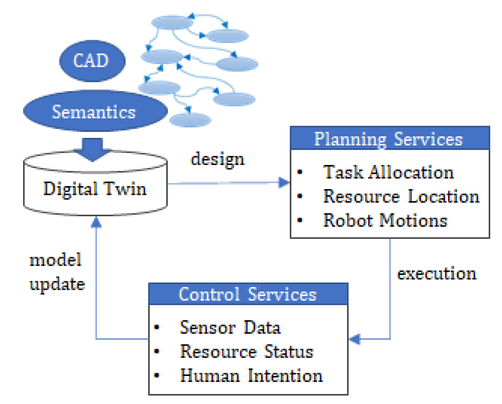
The proposed method supports the continuous design in flexible manufacturing systems exploiting digital twin technology. Based on Stark et al.’s DT definition [
28], a DT infrastructure, digitalizing multiple assets, is proposed to close the loop between the design tools and the physical world, as shown in
Figure 2. Three steps are followed to set up the DT system.
The first step includes the configuration of the DT during the design phase. Currently, production designers use various simulation tools to design the production system. However, the uncertainty on the shop floor during execution such as human operators’ unpredicted behavior or unexpected variations in the demand profile or in the resources’ availability is not captured sufficiently through these tools. The suggested DT includes a unified representation of the Product–Process–Resource system aiming to link the production design and execution phases. The configuration process involves the creation of smart digital models to represent multiple assets of the shopfloor, including the parts, processes, resources, and sensors. Having as a starting point the CAD models of the parts and of the production line, these models comprise (a) the semantic representation of each entity including its characteristic and capabilities as well as of the tasks that need to be executed, (b) the geometrical information that defines the spatial relation between the entities, and (c) uniform data structures able to synthesize multiple sensor data types. The target is to use these models for data sharing between multiple phases of the product lifecycle.
The second step involves the deployment of decision-making tools to derive alternative configurations of the production system using as input the DT models. These tools, wrapped as planning services, use AI to draw decisions on (a) how to optimally allocate the tasks among the available resources, (b) where to locate the resources for realizing optimal task plans, and (c) how to ensure collision-free resource trajectories, minimizing the stoppages of the task due to the existence of obstacles. The integration of planning services to the DT aims to bridge the gap between the physical world and its digital representation enabling production system’s reconfigurable behavior [
4].
The third step involves the deployment of control services for interfacing the involved hardware components, namely the robots’ controller, the human–machine interfaces, the sensors, and the tools. The target is to simplify the control integration and sensor data sharing. This results in an easier distribution of derived plans to the relevant resources. During execution, the DT is dynamically updated, retrieving real-time sensor data, resources’ status, and location as well as human input.
HRC Workplaces Re-Design Workflow
The proposed method aims to enable the operation of systems that employ human operators and flexible mobile robot workers. The mobility of these resources creates two-fold added value for the system: (a) the layout of the system can be autonomously reconfigured by re-directing the mobile robots in different workstations, and (b) the robots act as assistants to human operators increasing flexibility on the process execution [
5].
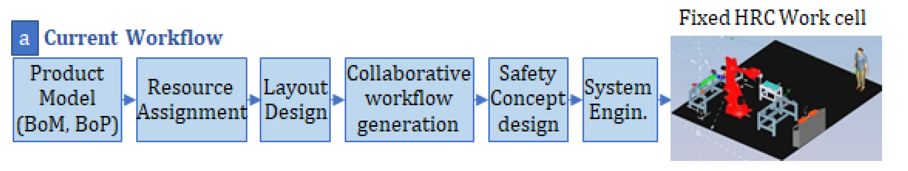
The design process of HRC workplaces operation commonly proposed in the literature follows the sequential workflow presented in
Figure 3 [
29]. The result of this process is a fixed HRC layout where the tasks and robot motions are pre-determined so to comply with the safety regulations [
30]. Human uncertainty is handled by isolated safety systems, leading to stoppages of production when the safety is compromised by human behavior.
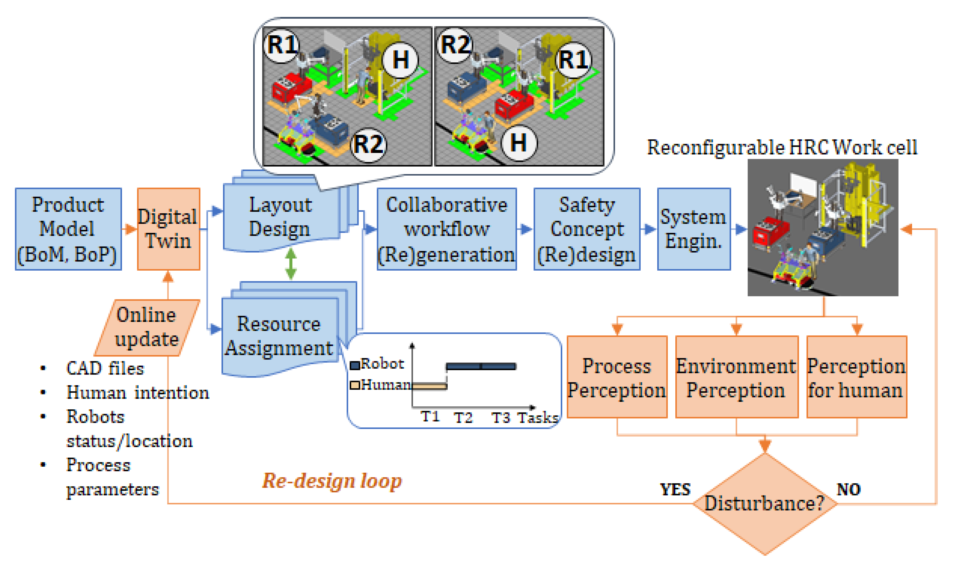
The proposed DT based re-design process aims to facilitate this dynamic system reconfiguration by transforming the design workflow, as shown in
Figure 4. The DT models include the information needed for optimizing the system’s layout by assigning human operators and mobile robots to perform tasks in the different workstations. During execution, a set of perception modules is deployed to monitor the execution, the environment, and human behavior through multiple sensors. These sensors capture 2D and 3D images. Consuming the relevant data structures of the DT, these data are synthesized to populate the real-time planning scene in the form of an occupancy map [
31].
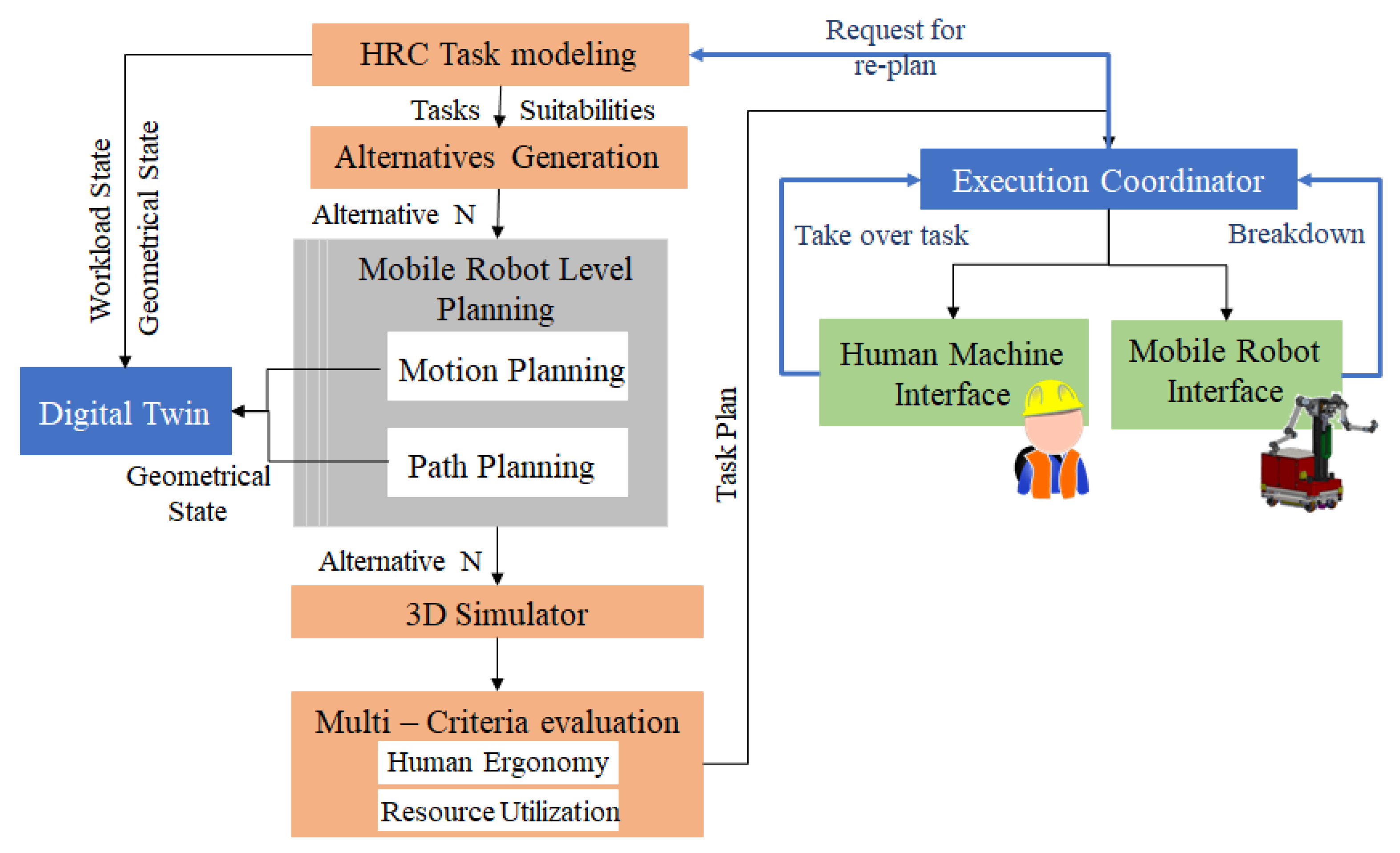
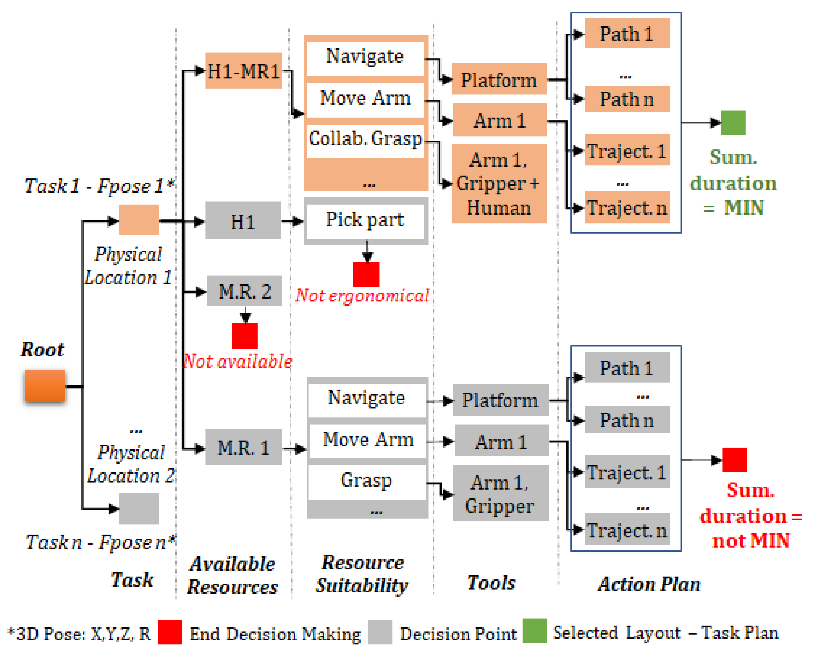
The decision-making logic implemented for the layout and task planning is visualized in
Figure 5. An intelligent search method [
1] is used to generate alternative configurations of the system consuming the 3D planning scene and the resources, tools, and task DT models. Each task model selected in the task layer is linked to the involved part model and its real-time location in the shopfloor. In the second layer, the availability of resources is assessed based on their real-time status, considering human operators (H), mobile robot workers (M.R.), and human–robot teams (H.MR.). In the third layer, based on resource capabilities including payload and available tooling, the suitability for the selected task is assessed. In the Tools layer, the fitting tooling is selected. In the last layer, the robots’ motion for each alternative is calculated consuming the 3D planning scene. Finally, the alternative with the minimum execution duration is selected and sent for execution to the physical system. In cases of disturbances in runtime, the planning services are triggered to re-design the workflow.
3. Implementation
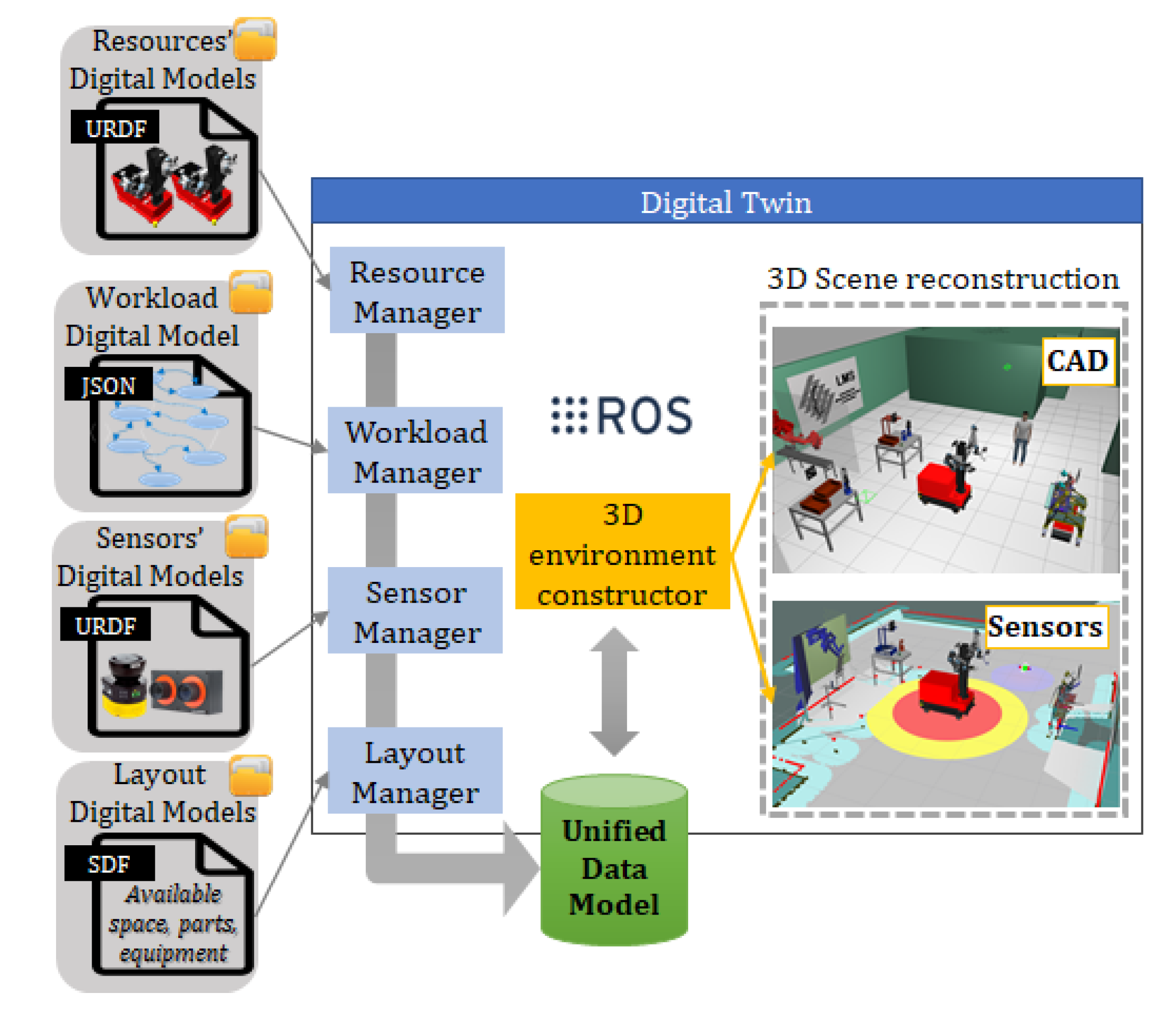
The overall architecture of the Digital Twin including the components deployed for the construction of the DT is visualized in
Figure 6. The integration and communication interfaces were established following the principles of ROS [
31] to enable data exchange among the different modules as well as scalability of the system in terms of adding new robot resources. The system is deployed in a PC running Ubuntu 16.04 and ROS Kinetic. The involved modules are described below.
The Resource Manager module is responsible for storing and broadcasting the Resources’ digital models. These models involve attributes such as payload, minimum velocity, location, status, kinematics transform configuration (.urdf), path (.yaml), and motion (.srdf) configuration. The Workload Manager stores the task models in a JSON format following a hierarchical modeling approach [
12]. The involved sensors’ configuration data such as ID, location, and Unified Robot Description Format (URDF) description are registered in the DT through the Sensor Manager. The captured data are published through dedicated topics. On top of these, the 2D and 3D data are combined and published in an additional topic so to facilitate their consumption by the planning services. The Layout Manager stores all CADs files related to static fixtures, parts, and products in .sdf format also defining the collisions, the inertia, and the mass parameters. The 3D environment constructor retrieves the locations of all parts, fixtures, sensors, and resources to construct an environment with a global world frame (using ROS Tf—library [
31]). It also provides an interface with ROS services and a topic to track and update the position of all parts inside the shopfloor based on the real-time updates coming from shopfloor sensors.
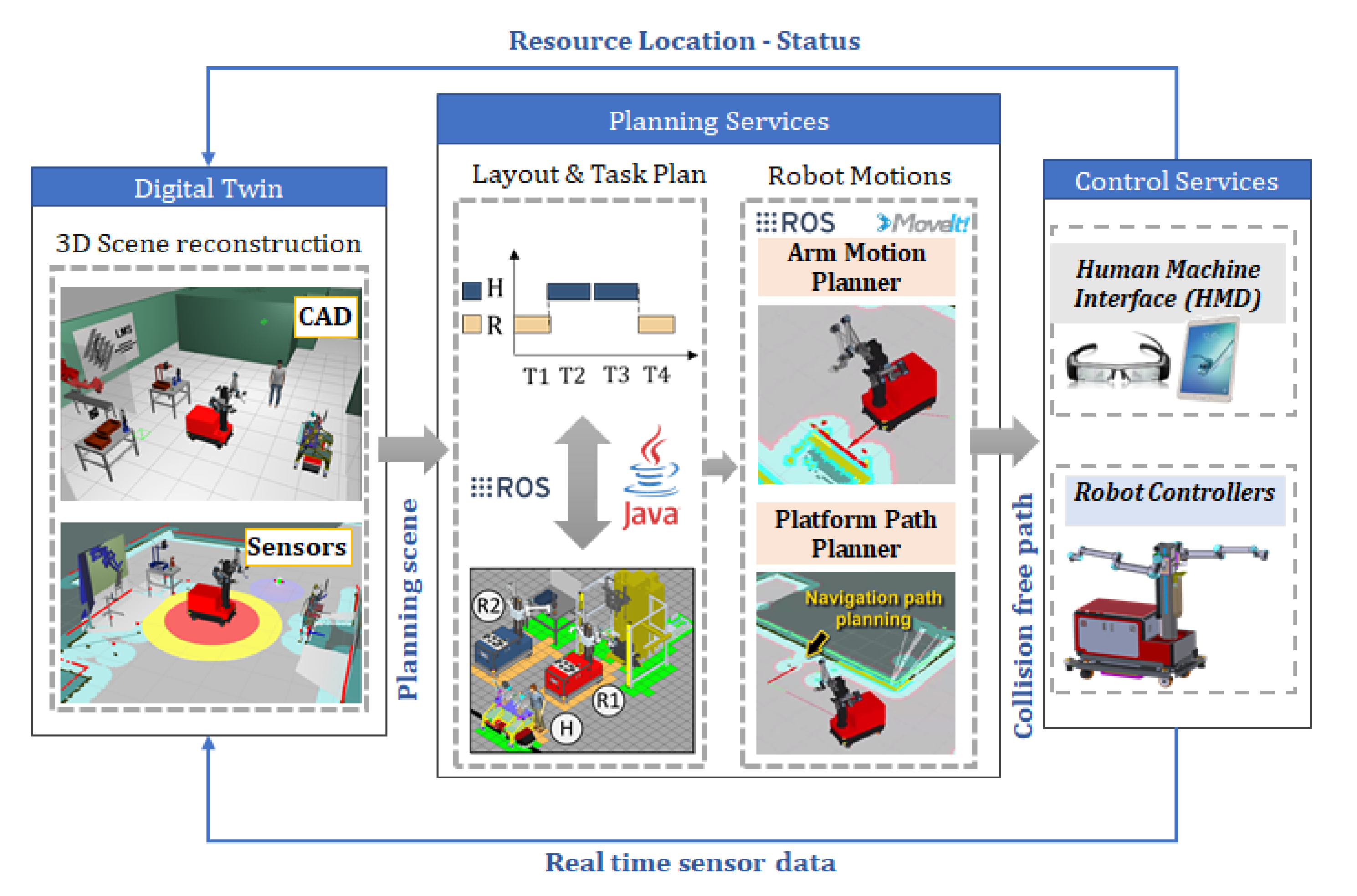
The integration of the DT with the planning and control services is visualized in
Figure 7. The layout and task planning modules are developed in Java. Regarding the robot motions, state-of-the-art algorithms for mobile platform path planning and robot arm motion planning are integrated in the system (gmapping, amcl, and ompl [
31]). The DT provides dedicated interfaces to these modules so for the latter to have access in the 3D planning scene and exchange data. The connection with the robot controller is established through ROS drivers, while the instructions for the tasks are sent to human operators in smart devices interfaces through ROSBridge.
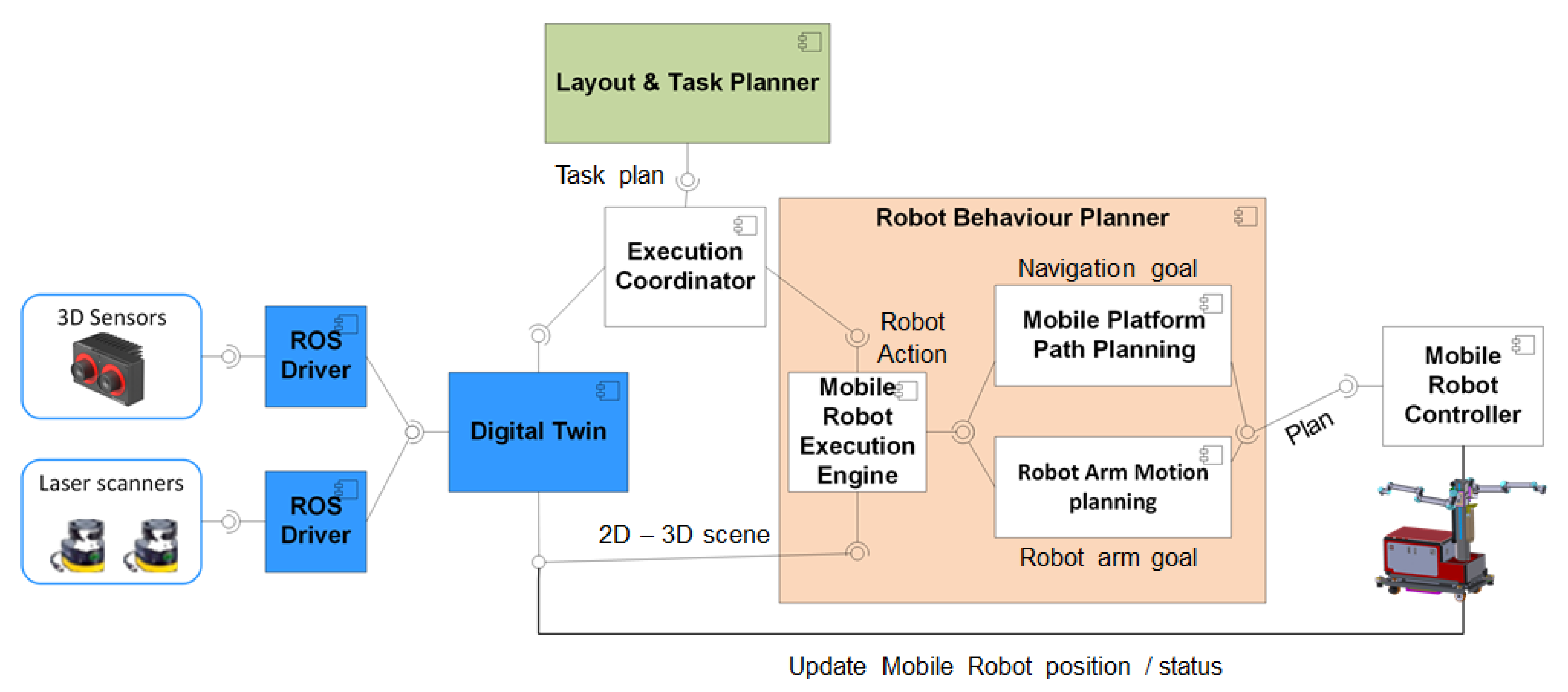
During execution, the DT is used for publishing the planning scene constructed through the elements described above. The component diagram presented in
Figure 8 details the connection and the established interaction among the different planning and control services with the DT.
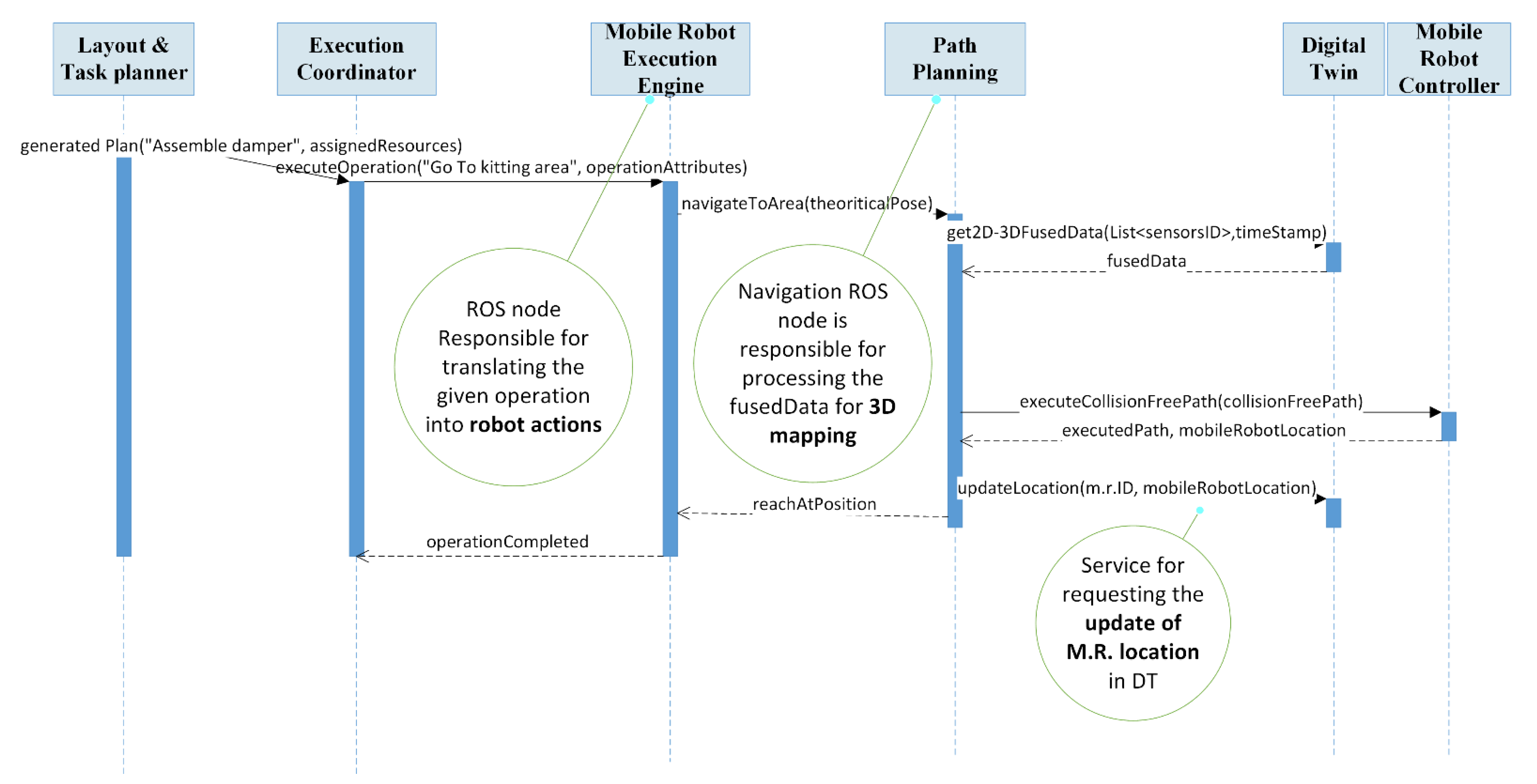
In order to efficiently accommodate the interaction among these modules, a service-oriented approach has been implemented. Under this approach, the exchange of information among the different resources is performed using peer-to-peer services. In
Figure 9, the provided sequence diagram details the communication among the different resources indicatively for the execution of a Navigation Task by a mobile robot.
4. Case Study
The section describes how the DT based re-design system has been deployed, tested, and validated in a real industrial case study. In particular, the system has been tested in an assembly line of an automotive company producing the front axle of a passenger vehicle. The current assembly line, deployed in the automotive factory, is configured in a fixed layout employing human operators, compression machines, and an automated screwing machine. The base part is loaded in an Automated Guided Vehicle (AGV) that moves along the assembly line. The process takes place in three working areas: (a) the pre-assembly working area, (b) the compression working area, and (c) the AGV working area. However, this set up raises two main challenges for the end user. (a) The first is hardware equipment limitations to accommodate the production of multiple product variants since the automated screwing machines can accommodate the screwing of only one axle model. When new models are added in production, a manual re-design and re-deployment of the system is needed. (b) The second is the strain caused in human operators, since they need to lift 480 compressed dampers of 6 kg weight in an 8 h shift. To overcome those limitations, the DT based re-design system is used to enable the production paradigm that employs mobile dual arm workers. The workers can (a) be re-located among workstations and by automatically changing tools perform operations for multiple parts and (b) undertake the heavy tasks, reducing operators’ strain.
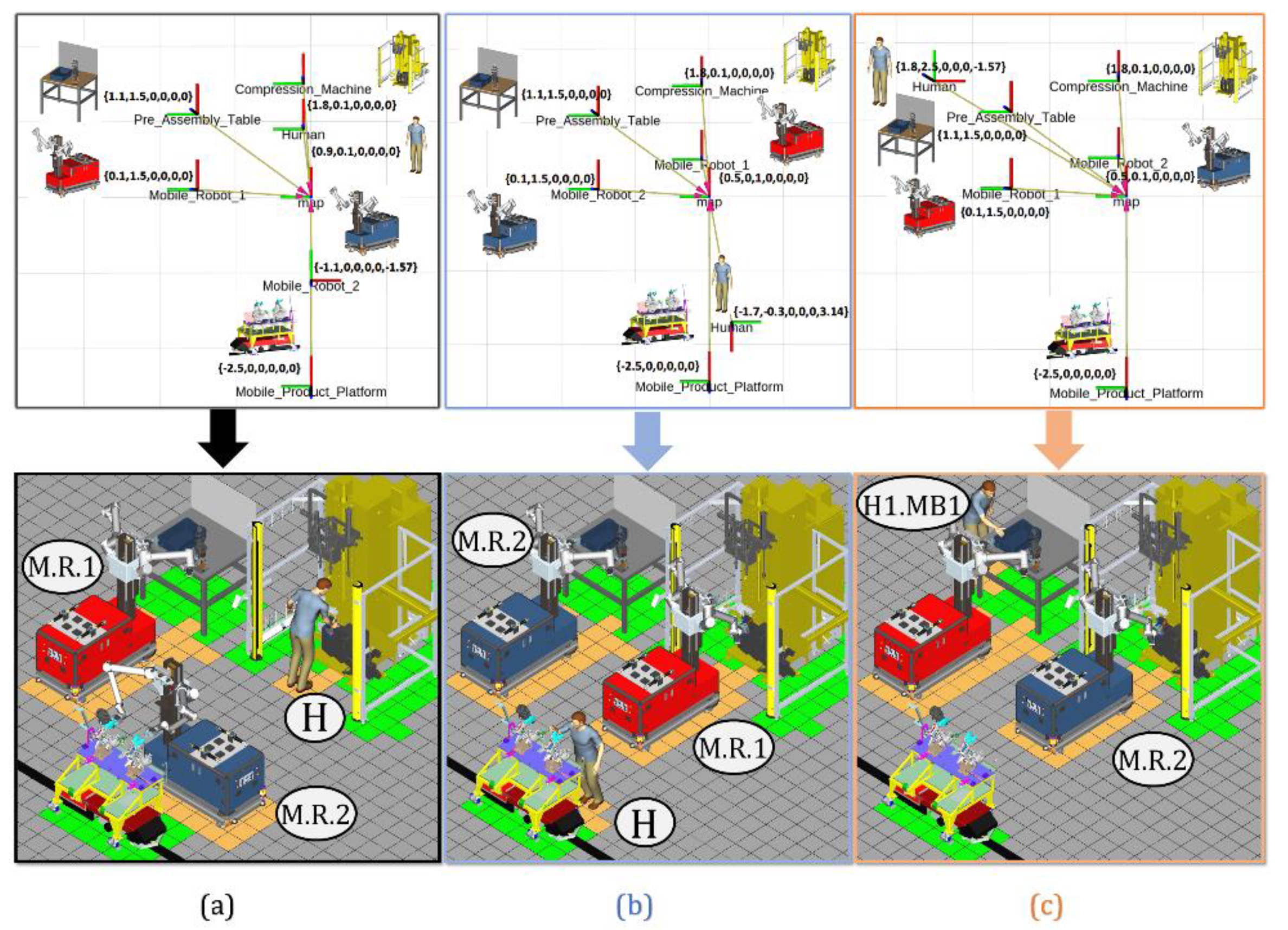
The DT-based system is used to generate alternative configurations of the system. Depending on the alternative task plan, the resources are located in different workstations, forming the initial layout of the system.
Figure 10 presents three indicative system configurations for the assembly of the axle that takes place in three working areas.
The generated alternatives are evaluated toward minimizing the processing time and optimizing the use of resources. To validate the alternatives against those metrics, the decision-making system is integrated with a GAZEBO 3D simulator [
32]. This simulator provided the values on these metrics for each configuration alternative. After all alternatives were validated, the optimal configuration was selected by the system. The selected task plan that is dispatched for execution is listed in
Table 1.
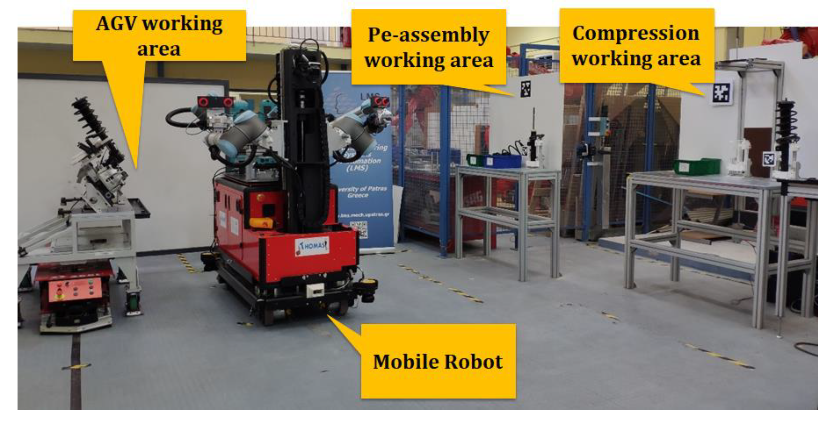
The selected configuration of the layout has been physically deployed in the Laboratory for Manufacturing Systems and Automation (LMS) Machine Shop as visualized in
Figure 11. This set up has been used for the execution of the assembly task plan as generated by the decision-making module.
In this study, we consider two cases that raise the need for system re-design during execution. The first case concerns execution disturbances that call for resource behavior level re-design when the robots’ motions need to be adjusted in online changes that occur in the environment. Currently, as mentioned above, AGVs are used in the factory. When a human operator gets close of one of the AGVs, the latter stops, and it only resumes its operation when the human moves away. In such a fenceless environment, these stops occur quite often during a shift, creating eventual delays in the process. This creates the need for the mobile robots to be able detect human operators, and instead of stopping, re-plan its path so to avoid them.
The second case concerns execution disturbances that call for Station Level re-design by re-organizing the remaining tasks to the involved resources. This case is of interest considering that in actual production, resources’ breakdown occur during execution. When these occur, the production stops, and typically, the contribution of the maintenance department is needed to resume the execution. The target is to use the DT-based system to minimize the stoppages of production due to resources’ breakdown by dynamically re-designing the tasks when these occur.
The next sub-section presents a quantification of the effect of using the DT-based system in the initial design of the system and in the occurrence of the two type of disturbances.
Results
Regarding the design of the production system, Discrete Event Simulation (DES) has been used for calculating the performance of the DT-based generated design assembly paradigm against current practice. Two different DES models were deployed in WITNESS Discrete Event Simulation Software, version 23 [
33]. The first model represented the current assembly line structure, modeling the execution time for each workstation. The tasks involved in each workstation were executed by human operators and by a compression machine. The execution time for these tasks was modeled based on relevant data provided by the automotive end user. The second model simulated the new set up of the production system that employs mobile robots to support human operators. The structure of the second model was designed based on the outcome of the DT-based system. This model as well incorporated the execution time of the tasks performed by the mobile robots, the human operators, and the compression machine. The execution time for human operators and the compression machine was modeled using the same source of information as in the first model. For modeling the time required for the mobile robots to execute their assigned tasks, the execution of the tasks by the robots was simulated in GAZEBO 3D simulator recording their duration.
The simulation time for both models was one year. The production throughput and the utilization of resources were recorded for both models during this simulated year of production. The results, shown in
Table 2, indicate a considerable improvement in the production throughput and utilization of operators’ availability by facilitating the reconfigurable HRC system.
Regarding the re-design of the system, below, we present the responsiveness of the system in two cases of execution disturbances against current industrial practice.
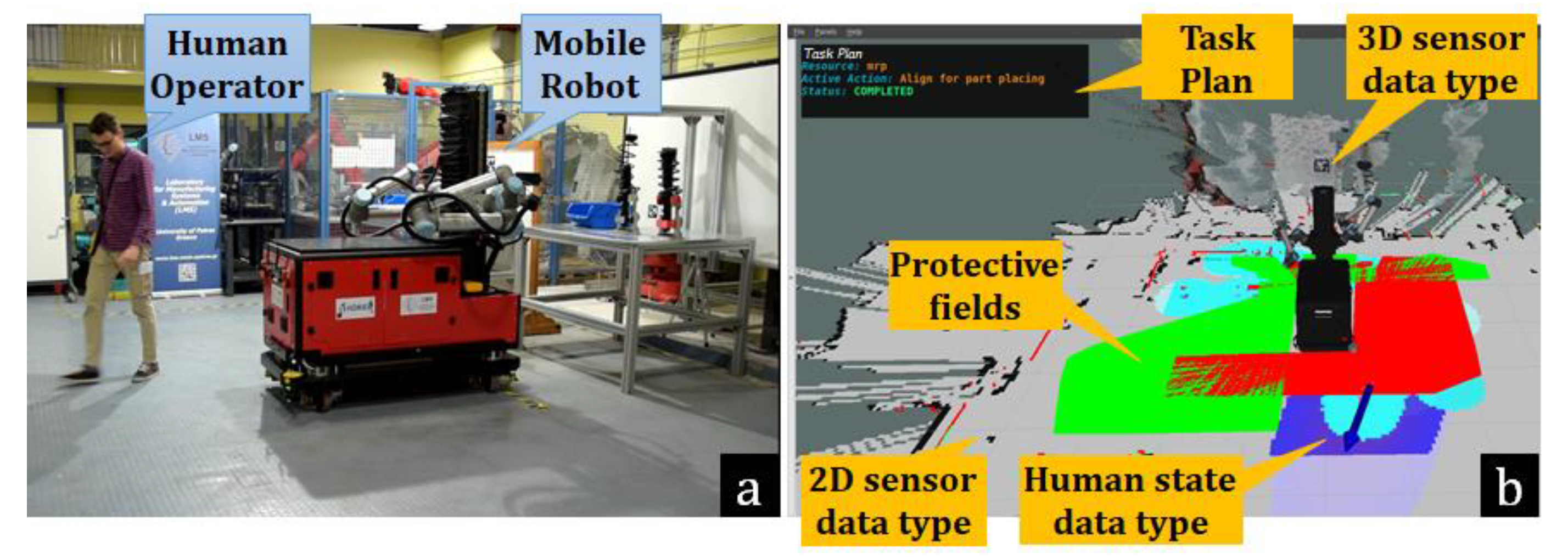
Figure 12 visualizes the 3D planning scene reconstructed by the DT based on the physical world real-time status. This 3D planning scene is generated by the combination of data captured by two laser scanners placed on the mobile platform and one stereo camera placed on the robot’s torso. By combining this information, the human presence and state is identified and included in the planning scene.
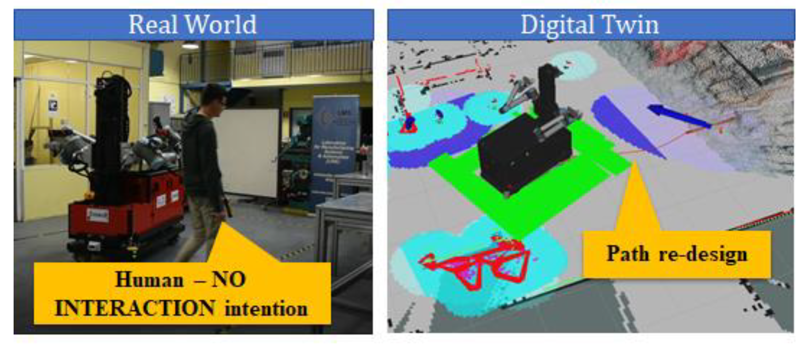
Case 1: The operator enters the common workspace, and his path intersects the mobile robot’s planned trajectory for 10 s. In current industrial practice, the mobile robot would stop, waiting for the human to move away and needing 1 s to resume its path. In the same case, the DT-based system will detect his NO INTERACTION intention and add human presence and state information in the planning scene. The mobile robot, instead of stopping, will re-plan its path in around 2 s, as shown in
Figure 13. To quantify this effect, in an 8 h shift, we consider that the human will block the robot path 200 times. As shown in
Table 3, the latter practice may reduce by 80% the overall delay caused by human presence.
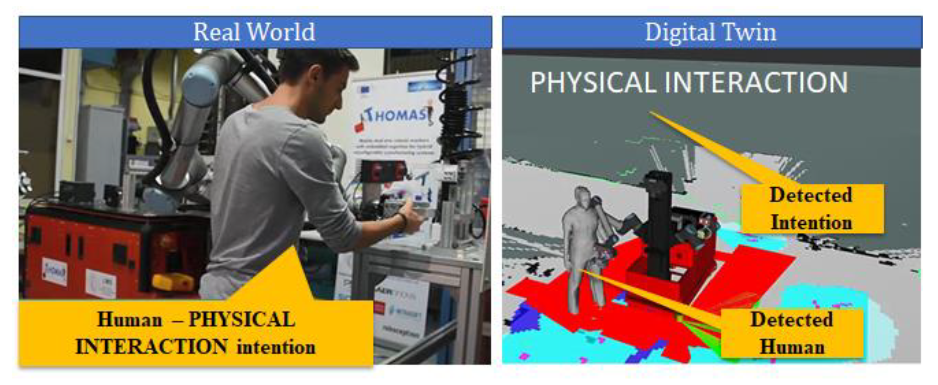
Case 2: Robot arm fails to grasp the damper. In a realistic set up, the robot may fail to execute a task due to occlusions in the cameras’ field of view, lighting conditions, etc. Through experimentation, we consider that in an 8 h shift, the robot fails 50 times. In current practice, the production manager would manually re-start the robot and correct its position, needing up to 70 s. Through our system, the operator himself can easily resume the execution by manually guiding the arm in the grasping position, as shown in
Figure 14, needing up to 21 s.
Table 3 shows the time saved by using the DT model functions.
5. Conclusions
This work discusses the use of DTs for designing and redesigning flexible production systems. These systems employ mobile dual arm robots that move across the factory undertaking multiple tasks, assisting humans. Exploiting this hardware ability, the DT based re-design system generates optimal configurations in terms of layout and task plans. The solution allows for online reconfiguration of the system by (a) dynamically re-assigning the tasks when unexpected events occur, (b) real time adjusting robots’ behavior so to ensure collision-free trajectories generation in unstructured environments. These are achieved reasoning on top of the sensor-based real-time scene reconstruction that is provided by the Digital Twin by synthesizing multiple sensor data.
The discussed DT-based system has been deployed, tested, and validated in a case study from the automotive sector. In particularly, mobile robot workers are introduced to assist human operators in the assembly of a vehicle’s front axle, which is performed fully manually in current practice. Discrete Event Simulation has been used to validate the performance of the suggested hybrid production system against current practice. The results show that by introducing mobile robot resources in the system, the production throughput as well as the resources’ utilization can be increased. To validate the effect of the DT-based system that enables this hybrid production paradigm, its effect in two cases of needed reconfiguration has been analyzed and quantified. This quantification proves that the suggested system enables the faster adaptability of the system when unexpected events occur against current practice, minimizing the stoppages of production
Future work will aim to a higher Technology Readiness Level (TRL) of the application so that it may be deployed in an industrial environment. Furthermore, the target is to enhance the digital models and decision-making tools so to incorporate the integration of dynamic risk assessment tools ensuring compliance to safety regulations. In addition, the DT-based system may be extended so to include the modeling and planning of the intra factory logistics operations required for supporting the assembly as well as for respecting the desired by the end user flowtime for the products.
Author Contributions
Conceptualization, S.M., G.M. and N.K.; methodology, N.K. and C.G.; software, C.G., K.L., A.C.B. and S.A.; validation, S.A. and P.B.; formal analysis, N.K. and S.M.; investigation, N.K., C.G. and K.L.; resources, S.M.; data curation, A.C.B.; writing—original draft preparation, N.K. and S.A.; writing—review and editing, N.K. and S.M.; visualization, C.G. and P.B.; supervision, N.K. and S.M.; project administration, N.K., G.M. and S.M.; funding acquisition, G.M. and S.M. All authors have read and agreed to the published version of the manuscript.
Institutional Review Board Statement
Not applicable.
Informed Consent Statement
Not applicable.
Data Availability Statement
Not applicable.
Conflicts of Interest
The authors declare no conflict of interest.
References
- Chryssolouris, G. Manufacturing Systems: Theory and Practice, 2nd ed.; Springer: New York, NY, USA, 2006. [Google Scholar]
- Michalos, G.; Kousi, N.; Makris, S.; Chryssolouris, G. Performance assessment of production systems with mobile robots. Procedia CIRP 2016, 41, 195–200. [Google Scholar] [CrossRef][Green Version]
- Stark, R.; Kind, S.; Neumeyer, S. Innovations in digital modelling for next generation manufacturing system design. CIRP Ann. 2017, 66, 169–172. [Google Scholar] [CrossRef]
- Makris, S. Cooperating Robots for Flexible Manufacturing; Springer: Berlin/Heidelberg, Germany, 2020. [Google Scholar]
- Kousi, N.; Michalos, G.; Aivaliots, S.; Makris, S. An outlook on future assembly systems introducing robotic mobile dual arm workers. Procedia CIRP 2018, 72, 33–38. [Google Scholar] [CrossRef]
- Erkoyuncu, J.A.; del Amo, I.F.; Ariansyah, D.; Bulka, D.; Roy, R. A design framework for adaptive digital twins. CIRP Ann. 2020, 69, 145–148. [Google Scholar] [CrossRef]
- Kousi, N.; Koukas, S.; Michalos, G.; Makris, S. Scheduling of smart intra—Factory material supply operations using mobile robots. Int. J. Prod. Res. 2019, 57, 801–814. [Google Scholar] [CrossRef]
- Tomiyama, T.; Lutters, E.; Stark, R.; Abramovici, M. Development capabilities for smart products. CIRP Ann. 2019, 68, 727–750. [Google Scholar] [CrossRef]
- Schleich, B.; Anwer, N.; Mathieu, L.; Wartzack, S. Shaping the digital twin for design and production engineering. CIRP Ann. 2017, 66, 141–144. [Google Scholar] [CrossRef]
- David, J.; Martikkala, A.; Lobov, A.; Lanz, M. A Unified Ontology Namespace for Enterprise Integration—A Digital Twin Case Study, Instrumentation Engineering. In Proceedings of the Instrumentation Engineering, Electronics and Telecommunications, Izhevsk, Russia, 24–26 November 2019; pp. 13–22. [Google Scholar]
- Tao, F.; Zhang, M.; Liu, Y.; Nee, A.Y.C. Digital twin driven prognostics and health management for complex equipment. CIRP Ann. 2018, 67, 169–172. [Google Scholar] [CrossRef]
- Tsarouchi, P.; Spiliotopoulos, J.; Michalos, G.; Koukas, S.; Athanasatos, A.; Makris, S.; Chryssolouris, G. A Decision Making Framework for Human Robot Collaborative Workplace Generation. Procedia CIRP 2016, 44, 228–232. [Google Scholar] [CrossRef]
- Erdős, G.; Paniti, I.; Tipary, B. Transformation of robotic workcells to digital twins. CIRP Ann. 2020, 69, 149–152. [Google Scholar] [CrossRef]
- Kousi, N.; Gkournelos, C.; Aivaliotis, S.; Giannoulis, C.; Michalos, G.; Makris, S. Digital twin for adaptation of robots’ behavior in flexible robotic assembly lines. Procedia Manuf. 2019, 28, 121–126. [Google Scholar] [CrossRef]
- Barricelli, B.R.; Casiraghi, E.; Fogli, D. A Survey on Digital Twin: Definitions, Characteristics, Applications, and Design Implications. IEEE Access 2019, 7, 167653–167671. [Google Scholar] [CrossRef]
- Florescu, A.; Barabas, S.A. Modeling and Simulation of a Flexible Manufacturing System—A Basic Component of Industry 4.0. Appl. Sci. 2020, 10, 8300. [Google Scholar] [CrossRef]
- Florescu, A.; Barabas, S.A. Simulation Tool for assessing the performance of Flexible Manufacturing Systems. In IOP Conference Series: Materials Science and Engineering, Proceedings of the 2nd International Conference on Manufacturing Technologies (ICMT 2018), Orlando, FL, USA, 19–21 January 2018; IOP Publishing: Bristol, UK, 2018; Volume 398, p. 012023. [Google Scholar]
- He, B.; Bai, K.J. Digital twin-based sustainable intelligent manufacturing: A review. Adv. Manuf. 2021, 9, 1–21. [Google Scholar] [CrossRef]
- Shao, G.; Helu, M. Framework for a digital twin in manufacturing: Scope and requirements. Manuf. Lett. 2020, 24, 105–107. [Google Scholar] [CrossRef] [PubMed]
- Resman, M.; Protner, J.; Simic, M.; Herakovic, N. A Five-Step Approach to Planning Data-Driven Digital Twins for Discrete Manufacturing Systems. Appl. Sci. 2021, 11, 3639. [Google Scholar] [CrossRef]
- Schütze, A.; Helwig, N.; Schneider, T. Sensors 4.0–smart sensors and measurement technology enable Industry 4.0. J. Sens. Sens. Syst. 2018, 7, 359–371. [Google Scholar] [CrossRef]
- Tao, F.; Zhang, H.; Liu, A.; Nee, A.Y. Digital twin in industry: State-of-the-art. IEEE Trans. Ind. Inform. 2018, 15, 2405–2415. [Google Scholar] [CrossRef]
- Novak, D.; Riener, R. A survey of sensor fusion methods in wearable robotics. Robot. Auton. Syst. 2015, 73, 155–170. [Google Scholar] [CrossRef]
- Nagla, K.S.; Uddin, M.; Singh, D. Multisensor Data Fusion and Integration for Mobile Robots: A review. IAES Int. J. Robot. Autom. 2014, 3, 131. [Google Scholar] [CrossRef]
- Santoso, F.; Garratt, M.A.; Anavatti, S.G. Visual—inertial navigation systems for aerial robotics: Sensor fusion and technology. IEEE Trans. Autom. Sci. Eng. 2016, 14, 260–275. [Google Scholar] [CrossRef]
- Bilberg, A.; Malik, A.A. Digital twin driven human–robot collaborative assembly. CIRP Ann. 2019, 68, 499–502. [Google Scholar] [CrossRef]
- Quigley, M.; Conley, K.; Gerkey, B.; Faust, J.; Foote, T.; Leibs, J.; Wheeler, R.; Ng, A.Y. ROS: An open-source Robot Operating System. In Proceedings of the ICRA Workshop on Open Source Software, Anchorage, AK, USA, 12–17 May 2009; IEEE: New York, NY, USA, 2009. [Google Scholar]
- Stark, R.; Fresemann, C.; Lindow, K. Development and operation of Digital Twins for technical systems and services. CIRP Ann. 2019, 68, 129–132. [Google Scholar] [CrossRef]
- Michalos, G.; Kousi, N.; Karagianis, P.; Gkournelos, C.; Dimoulas, D.; Koukas, S.; Mparis, K.; Papavasiliou, A.; Makris, S. Seamless human robot collaborative assembly—An automotive case study. Mechatronics 2018, 55, 194–211. [Google Scholar] [CrossRef]
- Michalos, G.; Makris, S.; Tsarouchi, P.; Guasch, T.; Kontovrakis, D.; Chryssolouris, G. Design Considerations for Safe Human–Robot Collaborative Workplaces. Procedia CIRP 2015, 37, 248–253. [Google Scholar] [CrossRef]
- Pyo, Y.; Cho, H.; Jung, L.; Lim, D. ROS Robot Programming; ROBOTIS: Seoul, Korea, 2017. [Google Scholar]
- GAZEBO Simulator. Available online: http://gazebosim.org/ (accessed on 13 May 2021).
- Lanner Witness Simulation. Available online: https://www.lanner.com/en-us/technology/witness-simulation-software.html (accessed on 13 May 2021).
| Publisher’s Note: MDPI stays neutral with regard to jurisdictional claims in published maps and institutional affiliations. |
© 2021 by the authors. Licensee MDPI, Basel, Switzerland. This article is an open access article distributed under the terms and conditions of the Creative Commons Attribution (CC BY) license (https://creativecommons.org/licenses/by/4.0/).


 ,
, 


