Article

Floor Heave Mechanism and Anti-Slide Piles Control Technology in Deep and Large-Span Chamber

1
College of Civil Engineering and Architecture, Shandong University of Science and Technology, Qingdao 266590, China
2
Shandong Key Laboratory of Civil Engineering Disaster Prevention & Mitigation, Shandong University of Science and Technology, Qingdao 266590, China
*
Author to whom correspondence should be addressed.
Appl. Sci. 2021, 11(10), 4576; https://doi.org/10.3390/app11104576
Submission received: 19 April 2021 / Revised: 5 May 2021 / Accepted: 10 May 2021 / Published: 17 May 2021
(This article belongs to the Section Civil Engineering)

Abstract

:
Based on plastic limit analysis, the deformation and fracture mechanism of the floor in the large-span chambers of deep mines are discussed and a similarity model test is carried out to verify the reliability of the theoretical analysis. The results show that the local shear failure first appears below the loading area and develops to the middle part of the test model with the increase in load; when the local shear failure develops to form a continuous sliding surface, continuous plastic flow deformation occurs; the distribution of the plastic zone and the deformation mode obtained from the similarity model test are basically consistent with the Hill-like deformation mode derived from plastic limit analysis. A control technology with anti-slide piles is proposed in order to deal with floor heave in large-span chambers on the basis of previous work. An approach for determining the supporting parameters of anti-slide piles is deduced. To deal with the floor heave in the −1100 level gangue winch room of the Huafeng Coal Mine, a comprehensive reinforcement scheme with anti-slide piles composed of discarded rails and anti-floating anchors is introduced for the floor heave control of the chambers. Site monitoring results show that the scheme not only effectively restrains the development of floor heave, but also ensures the long-term stability of the chamber floor.

1. Introduction

With shallow coal resources dried up and the demand for coal increasing in China, most of the coal mines in development are deep. Research has shown that maximum principal stress of some deep mining areas is vertical stress, which rises linearly with an increase in buried depth [1,2]. Therefore, the deformation and failure of the surrounding rock in roadways and chambers are increasingly serious with the increase in mining depth [3,4]. The problem of floor heave control in large-span chambers has especially become one of the main difficulties in deep mining.
Many scholars have presented different opinions on the failure mechanisms and evolution laws of floor heave in recent years. Chang et al. [5] obtained the plastic zone distribution, laws of deformation, and movement and stress distribution around the roadways without support by numerical modeling with Fast Lagrangian Analysis of Continua (FLAC) and in situ measuring. Gao et al. [6] established a mechanical calculation model of the floor and deduced the expression of critical load of buckling floor heave according to the thin plate buckling theory of elasticity. By long-term site monitoring, Liu et al. [7] indicated the main reason for floor heave in deep weak rock roadway is the open floor becoming the main place for deformation and stress release, and the weak broken floor rock is squeezed into the roadway under the action of in situ stress, under continuous plastic flow. Zheng et al. [8] studied the slip-line field of deep roadway floor by theoretical derivation, and deduced the expression of ultimate load and migration evolution characteristics of velocity field. Liu et al. [9] studied the deformation mechanism of sliding floor heave through the theory of plastic mechanics, divided the floor rock mass into zones, and obtained the critical failure depth of sliding floor heave and the minimum support load required to maintain stability. Fu et al. [10] considered the overall shear failure of floor rock mass under the action of the compression effects of two sides was the main cause of floor heave, which was similar to the overall shear failure in the foundation. Fang et al. [11] agreed with the above point and found that the rock mass fragmentation of two sides caused natural unloading, and high stress transferred to the floor with the compaction of the sides’ rock mass resulted in floor heave of roadways. Yue et al. [12] found that under graded loading, the floor deformation belonged to extrusion uplift floor heave, the failure of two sides belonged to brittle fracture failure, and the surrounding rock at the floor corner was subject to biaxial stress dominated by horizontal stress, whose failure was shear compression failure by a similar simulation test. Zheng et al. [13] found that the main factors leading to floor heave included the low strength of the surrounding rock, high stress levels, and the obvious rheological effect of surrounding rock through the true triaxial test on site. Li et al. [14,15] developed a large-scale geomechanical simulation test system suitable for simulating the whole process of excavation and support in deep roadways and studied the zonal fracture phenomenon of surrounding rock through the system.
Some scholars have provided effective prevention methods for floor heave according to concrete engineering practices [16,17], such as various types of contractible closed brackets [18], metal stents and inverted arches [19,20], bottom grooving [21] and blasting pressure relief [22], and a combination of floor bolts [23] and grouting [24]. Considering the need to know the floor deformation and mechanical properties of floor rock, it is difficult to effectively control floor deformation with conventional reinforcement and support methods.
This paper discusses the deformation and failure mechanism of the chamber floor in which the crustal stress field is mainly vertical stress based on the deformation and failure of the deep and large-span chamber floor in the Huafeng Coal Mine and describes a stability control technology combining anti-slide piles with anti-floating anchors and derives a method of designing support parameters from limit equilibrium theory. Practice shows that such a supporting scheme can effectively control floor heave and provide good economic and social benefits.

2. Discussion on the Floor Heave Mechanism in Deep Chambers

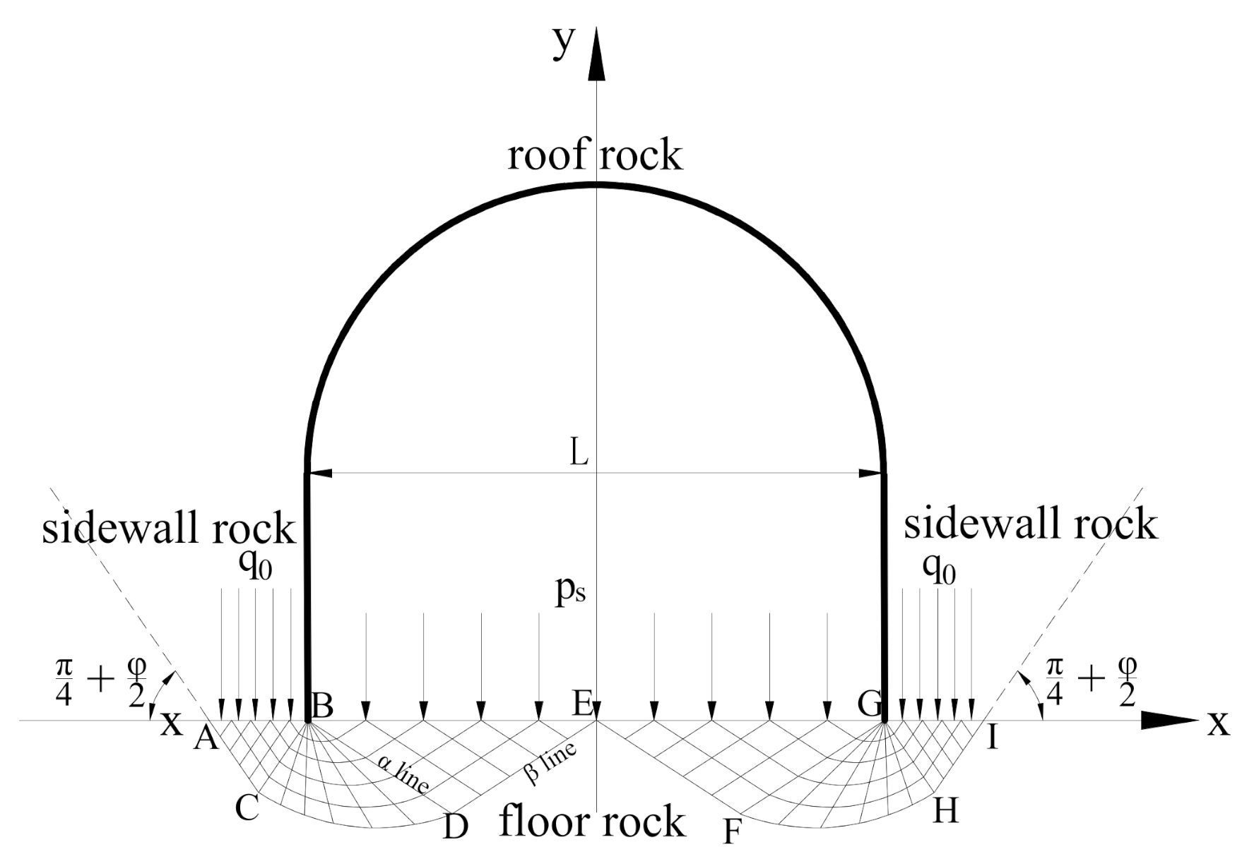
2.1. Plastic Flow Characteristics of the Floor in Deep Chambers

The underground chamber is a composite structure composed of a roof, floor, and two sides. Before excavation, the underground rock mass is in a triaxial stress equilibrium state. Research suggested that after excavation, due to the redistribution of internal stress in the rock mass, the weight of overlying rock mass is transferred to the two sides of the roadway [25]. In weak rock roadways, the floor rock is mostly shale, sandstone, and other weak rocks with low strength. When the load transferred to the floor by the two sides reaches or exceeds its yield strength, the compression mold effect occurs, which results in the overall shear failure of floor rock mass, and the floor rock mass will enter the plastic flow state. Supposing the floor rock mass is an ideal rigid plastic material that follows the Mohr–Coulomb yielding criterion, and the effect of rock gravity is ignored, we built a slip line field of large-span chamber floor in yield state, which resembled a Hill slip line field according to deformation characteristics of floors in a large amount of deep large-span chambers [26]. The slip line field is shown in Figure 1, where we consider the load transferred from the roof and sides to the floor q 0 and the supporting load (such as loads from anti-floating anchors) of the chamber floor p s . It should be noted that a Prandtl slip line field should be used for a small-span tunnel or chamber.

2.2. Ultimate Bearing Capacity of the Floor in Deep and Large-Span Chambers

From Figure 1, the normal stress of the floor σ n is equal to supporting resistance p s and shear stress τ n is always zero on the BE boundary, for ∆BDE is a uniform stress zone. Therefore, mean stress and its included angle with the x-axis of any point within ∆BDE are shown as Equation (1):
  p D = p s + c cot φ 1 sin φ , θ D = π 4 φ 2
where c and φ are the cohesion and internal friction angle of floor rock, respectively.
Similarly, according to assumptions, we derive σ n = q 0 and τ n = 0 on the AB boundary, so the following equations in ∆ACB can be obtained:
p C = q 0 + c cot φ 1 + sin φ , θ C = 3 π 4 φ 2
The stress distribution in ∆BCD is a kind of degenerate Riemann problem [27]. According to geotechnical plastic mechanics and the properties of the slip line, the equation between mean stress and its included angle on β lines can be simplified as:
ln p C + 2 θ C tan φ = ln p D + 2 θ D tan φ
q 0 is the ultimate bearing capacity of the deep and large-span chamber and can be expressed by Equations (1) and (2):
q 0 = ( p s + c cot φ ) exp ( π t g φ ) t g 2 ( π 4 + φ 2 ) c cot φ
The contribution of support resistance p s to the bearing capacity of the floor can be derived from Equation (4):
q s = p s exp ( π t g φ ) t g 2 ( π 4 + φ 2 )
When the stress from the roof and sides reaches or exceeds q 0 , the floor rock enters into plastic flow state, which results in continuous deformation.

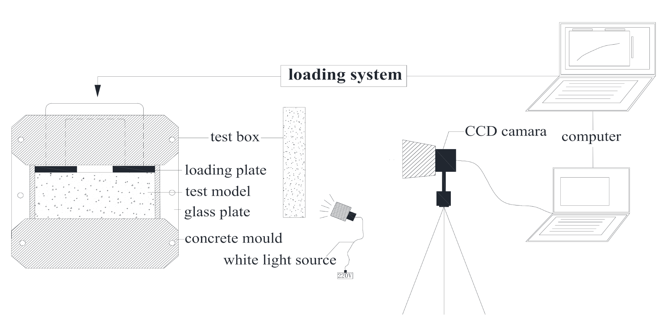
3. Model Test Based on Digital Speckle Correlation Method

In essence, the plastic flow deformation of the chamber floor is the overall shear failure caused by the insufficient bearing capacity of the floor rock mass, which is similar to the overall shear failure of the foundation. Therefore, the floor can be regarded as foundation bearing load transferred from the two sides. To investigate the plastic flow deformation failure mechanism of weak rock chamber, a set of floor deformation measurement systems was designed, which consists of a simulation test device and a digital speckle correlation measurement system. This system can directly obtain the digital speckle images before and after floor deformation through contrasting, through which the instantaneous displacement and strain fields were obtained, describing the movement law and deformation and failure process of the floor rock mass under loading.

3.1. Digital Speckle Correlation Method

The digital speckle correlation method regards the random distribution of speckle on the model’s surface as a carrier of the deformation and movement information. Through collecting and recording the speckle field on the model’s surface before and after deformation, the displacement vector of each speckle is obtained after deformation and the strain field is calculated through displacement. Therefore, the application of the digital speckle correlation method to the deformation study of a floor may well-reveal the failure mechanism and deformation evolution law of the floor and verify the reliability of plastic limit analysis.

3.2. Test Scheme

The self-developed chamber floor deformation measurement system consists of a simulation test device, loading system, and two-dimensional digital speckle correlation measurement system. The schematic diagram is shown in Figure 2. The two-dimensional digital speckle correlation measurement system is composed of a Charge Coupled Device (CCD) camera, camera fixator, image acquisition card, Light Emitting Diode (LED) white light source, computer, etc. The high-resolution camera in collaboration with sub-pixel processing technology enable micron-level measurement accuracy of the system, better than 0.02 pixels. Compared with traditional measurement systems, its accuracy can be improved 100 times. The loading process was carried out on a TAW-2000 microcomputer-controlled electro-hydraulic servo rock triaxial experimental machine. Before loading, artificial speckle treatment should be carried out on the test model’s surface. In order to avoid the influence of material transparency on the shooting effect of a CCD camera, a layer of black paint should be sprayed on the surface of the model before the artificial speckle is created. After speckling, the test box (305 × 150 × 300 mm) holding floor model was placed into the triaxial experimental machine. In order to capture the whole process from the stable state to the instability failure of the model, the displacement loading mode was adopted and the loading rate was set to 2 mm/min. The continuous digital images obtained in the loading process were analyzed by two-dimensional Digital Image Correlation Processing Software (DIC Processing Software). The DIC Processing Software processed the speckle images before and after deformation with grey processing and an analog-to-digital conversion operation; then, the displacement field, strain field, and displacement vector field of the floor model at different times could be obtained.

3.3. Analysis of Test Results

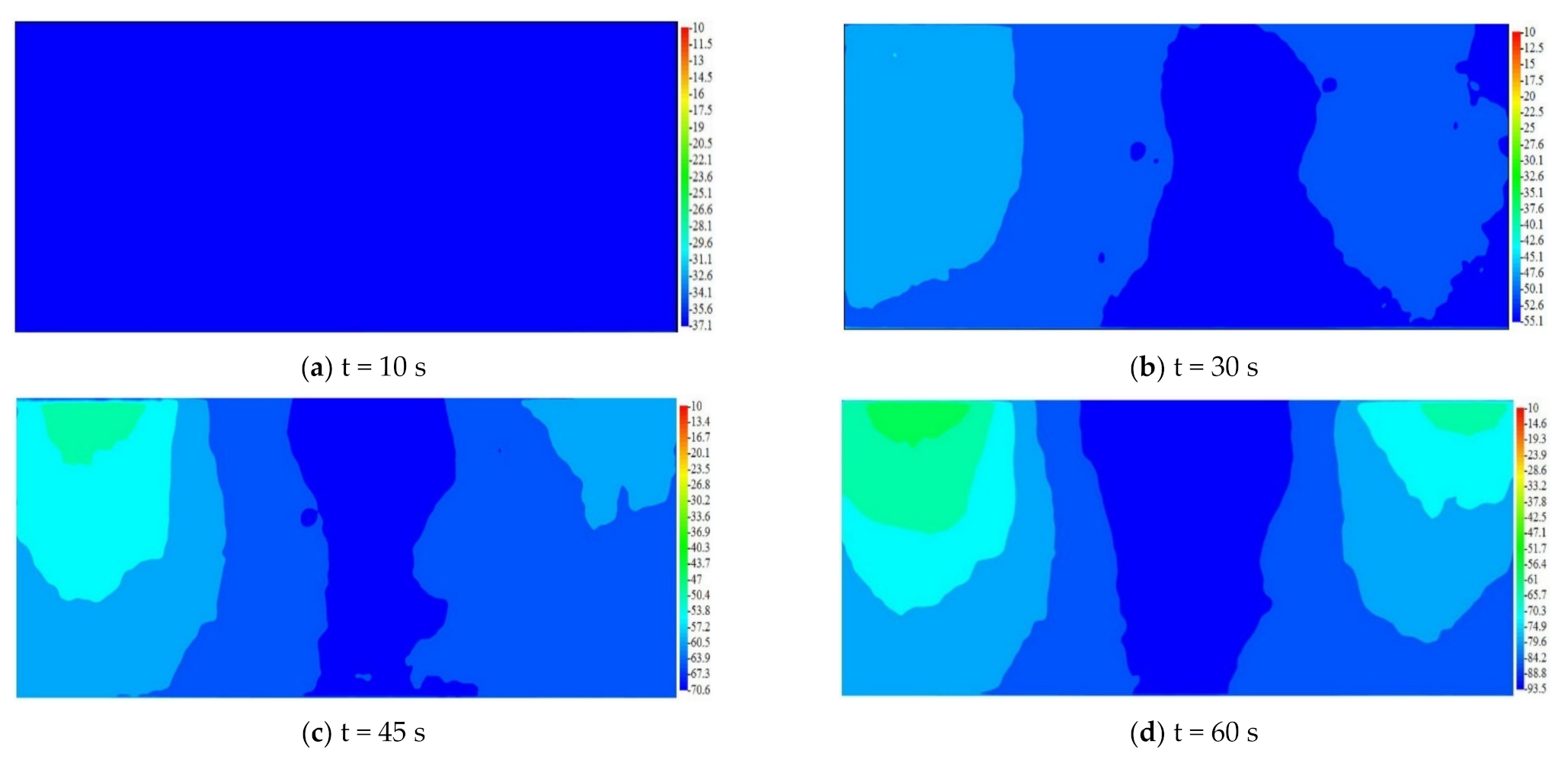
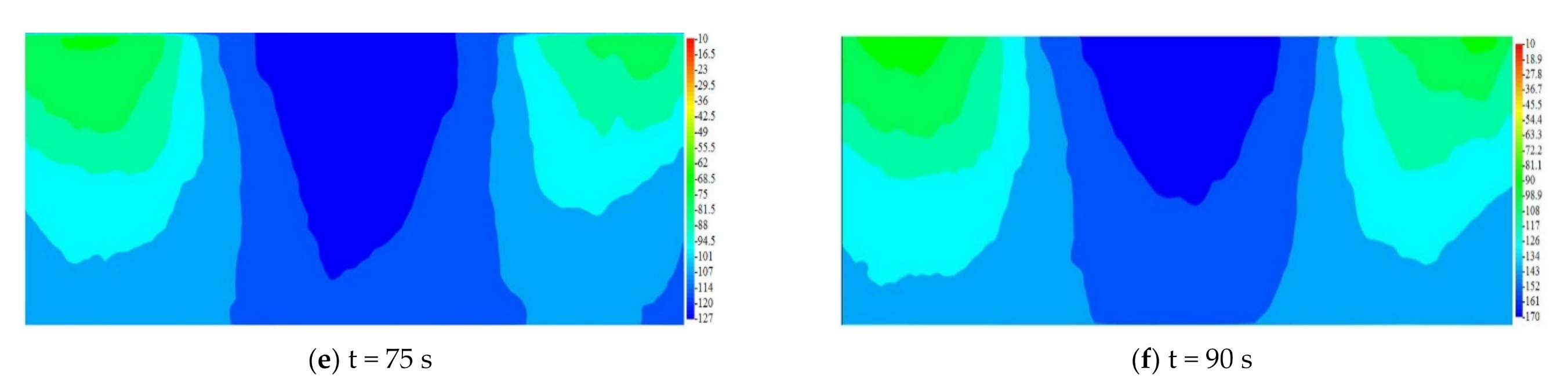
3.3.1. Analysis of Plastic Zone Range and Distribution Law

Batch processing by DIC Processing Software was carried out on speckle images obtained from the test and the displacement nephograms in the Y direction, and vector graphs at different times are shown in Figure 3 and Figure 4, where the unit of the vertical axes is pixel (1 mm is equal to 8.64 pixels). The displacement in the Y direction and the displacement vector of different speckles on the mode’s surface can be obtained because different colors correspond to different pixel values.
From these displacement nephograms, an approximate inverted triangle deformation area appeared below the loading plates first where local shear failure arose, and its range expanded to the lower part of the model with continuously increasing load; then, the deformation was gradually transferred to the middle part. When the load increased to a certain extent, the middle part of the model shifted upward under the extrusion of the deformation zone on both sides, which means continuous plastic flow deformation occurred.
From these displacement vector graphs, we also found that there was an upward movement in the two sides of the middle part under the extrusion of each deformation zone, and the deformation of the midpoint in the middle was largest. The movement was not overall upward movement, whose deformation mode is consistent with the Hill-like deformation mode.

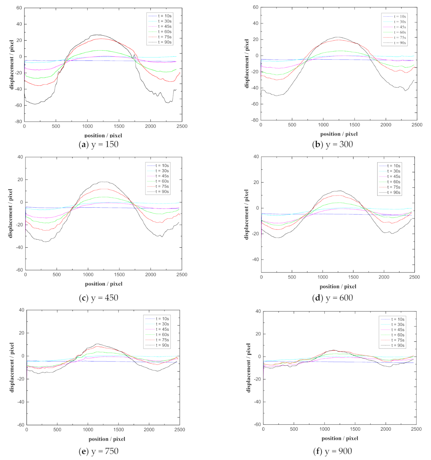
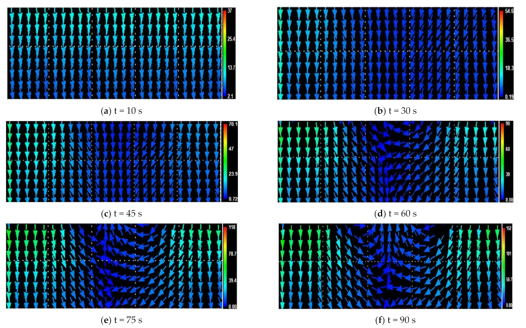
3.3.2. Analysis of Displacement Evolution Law

The deformation of speckles in six horizontal sections (y = 150, y = 300, y = 450, y = 600, y = 750, and y = 900) in Figure 5 were extracted from the displacement nephograms in the Y direction at different times. The abscissa correspond to the starting and ending ranges of the horizontal sections.
The deformation curves in Figure 5 show that the displacement of each horizontal section is continuous and the evolution laws of displacement are basically the same, which are as follows:
  • At the initial stage of loading, the displacement of each section is approximately a straight line and the value of each point is negative, which indicates that the overall vertical compression deformation occurs when the load is small, which is elastic and recoverable;
  • With the increase in load, the deformation of each section appears as a zoning phenomenon, that is, in the intervals of (0,750) and (1750,2500) in the X direction, the deformation continues to develop along the Y-axis in a negative direction, and the greater the load, the greater the deformation; whereas in interval (750,1750), the deformation continues to develop along the Y-axis in the positive direction, and the greater the load, the greater the deformation;
  • The deformation of the midpoint in interval (750,1750) is the largest, whereas the deformation on both sides of the midpoint is relatively small, which is consistent with the Hill-like deformation mode of central uplift.
Comparing different horizontal sections in Figure 5, we found that the closer the section to the loading plate, the larger the deformation, and the farther the section s to the loading plate, the smaller the deformation. On the section y = 900, which was farthest away from the loading plate, the displacement changed little under different loads, but affected by the range of camera, the section with displacement 0 could not be captured. However, it could still be inferred that the range of deformation was limited; in other words, the range of the plastic zone was limited, which is consistent with the results of theoretical analysis. If the influence range of the plastic zone can be determined and the relationship between the width of the chamber and the influence range can be obtained, they can provide a reference for the scientific design of floor support.

4. Anti-Slide Pile Control Technology and Supporting Parameter Determination

4.1. Length Determination of Anti-Slide Pile

Anti-slide pile is a common retaining structure in foundation pit and slope reinforcement engineering [28]. The principle of its resisting slope sliding is balancing the load of the pile’s two sides through the bottom pile penetrating into the stable slide-bed. Usually, bored piles whose diameter are less than 300 mm call for micro anti-slide piles, which not only have better anti-sliding ability, less masonry, and more flexible layout, but also bear greater shear stress by close arrangement. The above analysis of floor flow characteristics reflects that the essential cause for floor heave is the continuous deformation of floor rocks breaking along the potential sliding surface (such as ACDE in Figure 1). Consequently, laying micro anti-slide piles perpendicular to the slip line of the chamber floor can effectively control plastic flow deformation and achieve the purpose of floor stability. The concrete method is as follows: two anti-slide piles are arranged along the chamber, which pass through the central sector slip line zone and anchors at the stable rigid zone.

4.2. Formatting of Mathematical Components

According to mechanism of anti-slide pile controlling floor heave, the piles should pass through central sector BCD in Figure 1 and anchor in stable rock. In the BCD zone, the expression of logarithmic spiral CD is shown in Equation (6):
r = B D ¯ exp ( δ tan φ )
where r is the radius vector, δ is the angle between the initial and current vectors (when counterclockwise, δ is defined as positive), and B D ¯ = L 4 sec ( π 4 φ 2 ) .
From vertical arrangement, the length of anti-slide piles in the sliding zone can be calculated as:
L b = L 4 sec ( π 4 φ 2 ) exp ( π 4 + φ 2 ) tan φ
The total length of anti-slide pile is shown in Equation (8):
L p = L a + L b + L c
where L a is the length of anti-slide pile exposed out of the rock and is the thickness of reinforced concrete; L c , the anti-slide depth, is the length of he anchorage.

4.3. Bearing Capacity of Anti-Slide Pile

The thrust acting on free section of anti-slide piles is uniform because piles are vertically downwards along point B, which means piles are located on α line (straight line). Similar to the method in Section 4.2, loads working on anti-slide piles per meter can be obtained:
q p = q 1 cos 2 φ 1 + sin φ exp [ ( π 2 φ ) tan φ ]
where q 1 = q q 0 ; q 1 is residual thrust while q is actual load transferred to floor and q 0 is ultimate bearing capacity of floor without anti-slide piles.
The strength of anti-slide pile is calculated on the basis of design methods in slope and foundation engineering in such a circumstance. The shear stress is derived by shear strength:
τ = q p L b 2 n A
where A is the cross-sectional area of anti-slide pile; n is pile number per meter.
The effect which residual thrust contributes to bearing capacity of floor can be simplified form Equations (9) and (10):
q 1 = 2 n A τ ( 1 + sin φ ) L b cos 2 φ exp [ ( π 2 φ ) tan φ ]

5. Engineering Application of Anti-Slide Pile to Controlling Floor Heave

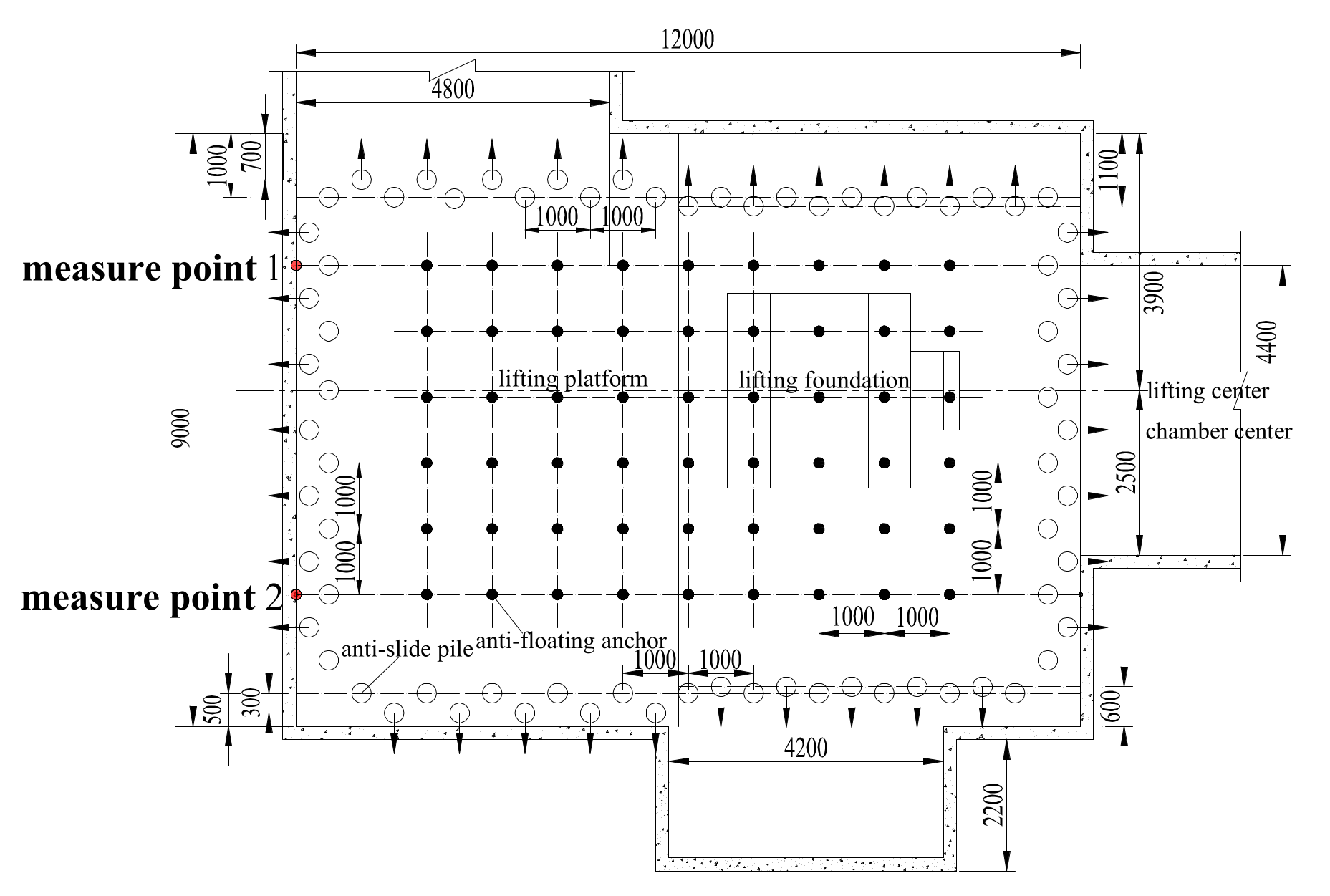
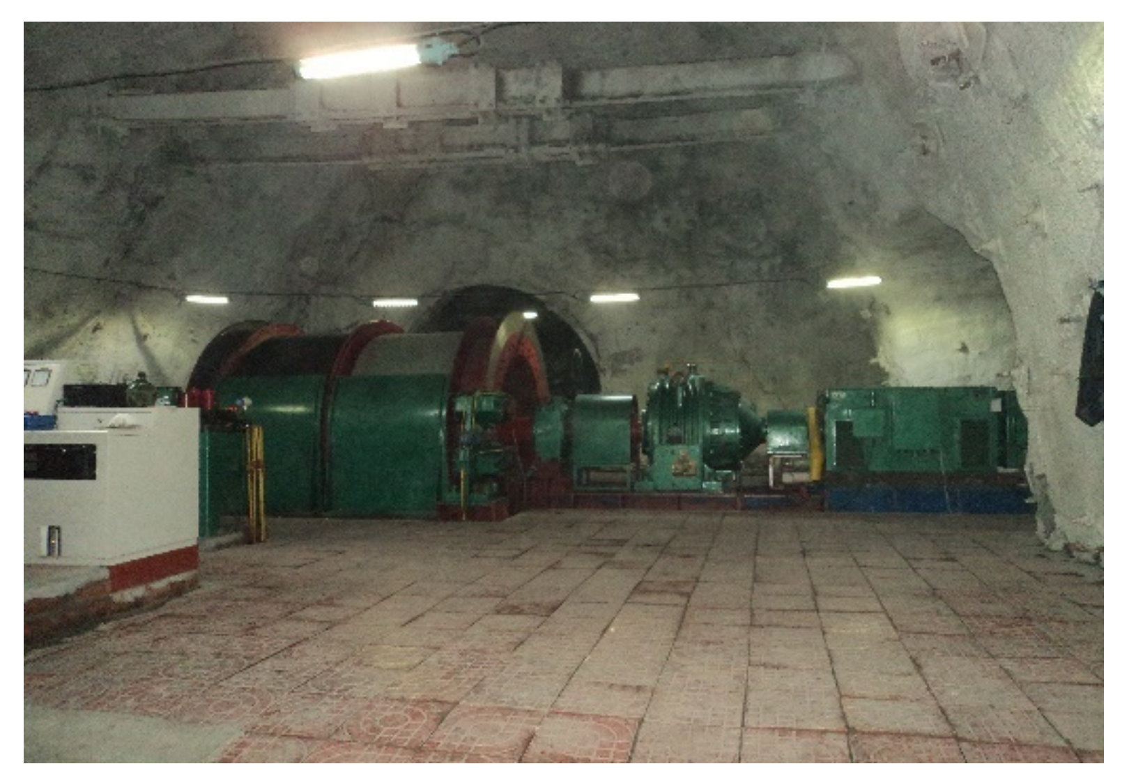
5.1. General Engineering Situation

The gangue winch room in the Huafeng Coal Mine lies at the −1100 level, the vertical buried depth of which is 1230 m. The designed straight wall semicircle arch section was 10.4 × 6.4 m (net width × net height), where the roof of the winch room was supported with a combined support scheme with high-strength bolts, prestressed anchors, and U-type steel stents, which met the use requirements. The floor of the winch room is low-strength argillaceous sandstone whose average compressive strength was 54.3 MPa. The floor rock was supported just by anchors in the corner and concrete sprays. According to the experience from winch rooms in the same condition, floor rocks would break at a fast speed. Further, the floor was renovated almost every year, which seriously affected normal production and safe hoisting. Measurement after excavation showed that the vertical stress in the sidewall rock of the chamber reached 33.9 MPa. There was no effective support means for floor heave control of the winch room with a span of more than 10 m.

5.2. Support Scheme of Chamber Floor

Considering the characteristics of the winch room and even force, we applied anti-slide pile and anti-floating anchors to control floor heave and achieve the goal of long-term stability.
The material of the anti-slide pile was waste rail, whose parameters are shown in Table 1. The diameter of drilling was 180 mm, with C30 concrete grouting. The anti-floating anchors were GY38 hollow self-drilling grouting anchors, whose parameters are shown in Table 2. Two rows of anti-slide piles were laid around the chamber, with a spacing of 300 mm and array pitch of 500 mm. The upper anti-slide pile and chamber floor were poured together.

5.3. Length Calculation of Anti-Slide Pile

The cohesion of argillaceous sandstone is 1.86 MPa and the internal friction angle is 22°. The chamber span L is 10.4 m while the thickness of reinforced concrete is 0.7 m and the anchorage length is 1.8 m. Considering the foundation of the winch room is 0.7 m, the length of anti-slide pile is calculated as 4.61 m. To facilitate construction, we used 5.0 m.

5.4. Stability Check of Floor
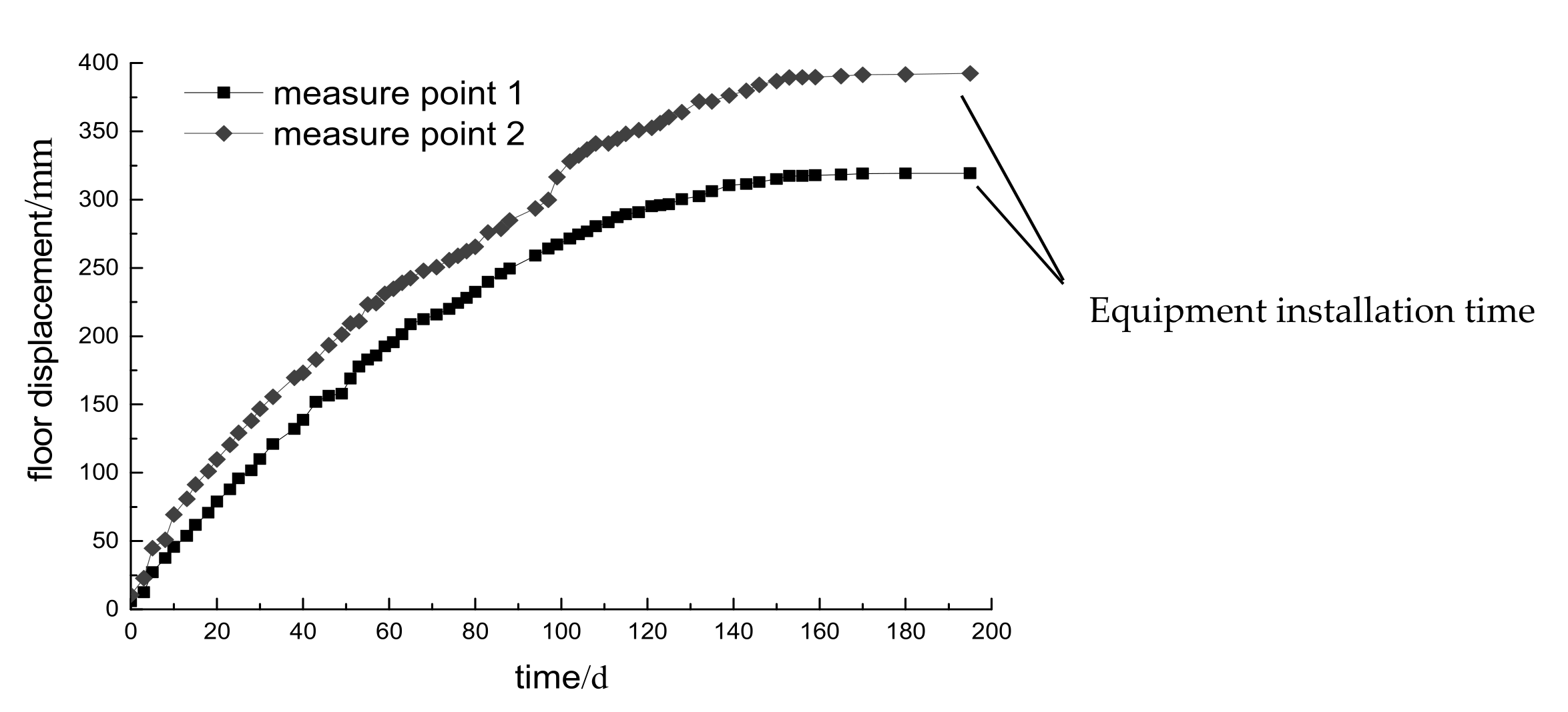
The ultimate bearing capacity of the floor without support measures q 0 is 31.40 MPa from Equation (4). The support force provided by the anti-floating anchor is 0.28 MPa, so the contribution to bearing capacity of the anti-floating anchor q s derived from Equation (5) is 2.19 MPa. In Equation (11), n = 2; A = 28.39 cm2; the shear strength τ is 0.5 σ b . Taking account of such parameters, the contribution value of the anti-slide pile q 1 is 2.08 MPa. Therefore, the ultimate bearing capacity of the floor in this scheme is 35.67 MPa by adding q 0 , q s , and q 1 , which is larger than 33.9 MPa and well-meets the need for stability.

5.5. Support Effect

Measure points were laid on the floor of the winch room in order to monitor the deformation after excavation. Monitoring was carried out once a day by means of the total station instrument. The layout of the measure points is shown in Figure 6. Figure 7 depicts the displacement curve of the two measure points of the winch room.
From the displacement curves, continuous deformation arose during the days (about 60 days) before construction and under construction of anti-slide piles and anti-floating anchors. After construction, the deformation rate decreased significantly with the growth in the strength of the support material and the completion of stress adjustment. Over time, especially after the equipment was installed, the floor tended to be stable. The whole deformation process was consistent with the general law of chamber stability and satisfied the use requirements. After nearly three years, the floor is still in a stable state. Figure 8 depicts the gangue winch room floor one year after construction.

6. Conclusions

Deformation and failure mechanism of floor heave in the deep large-span chamber were discussed by means of plastic limit analysis theory. A model test based on two-dimensional digital speckle correlation method confirmed the reliability of the theoretical analysis. On this basis, we proposed anti-slide pile controlling of floor heave in the same situation and derived the supporting parameters of the anti-slide pile (including length and anti-sliding ability). Based on the application of the anti-slide pile in the gangue winch room of Huafeng Coal Mine, the following conclusions were obtained:
(1)
Under the action of the compression mold effect, the local shear failure first appears below the loading area and develops to the middle part gradually; when the load increases to a certain extent, the local shear failure develops to form a continuous sliding surface and continuous plastic flow deformation occurs.
(2)
The essential mechanism of the anti-slide pile controlling of floor heave is that the floor enters into plastic flow in the form of shear slip under stress from vertical load. Laying anti-slide piles perpendicular to the slip surface through the floor can resist shear deformation and realize the goal of stability.
(3)
For anti-slide piles, controlling floor heave was proposed according to plastic limit theory; the limit analysis of slip line theory provided a theoretical basis for the design and parameter determination of the anti-slide pile.
(4)
An example showed the scheme combining anti-slide piles with anchors has strong supporting capacity to control floor heave in deep chambers, which can meet the needs of using the floor under the limit equilibrium state. The combination is beneficial to ensuring the uniform stress of the floor in large-span chambers and maintaining the floor in good condition.
(5)
Practice proved that controlling floor heave by anti-slide piles provides the advantages of a simple process, fast construction, low cost, and significant effects, which have values for their popularization and application in similar conditions.

7. Patents

Patent CN 112345372 A resulted from the work reported in this manuscript.

Author Contributions

Conceptualization, J.S. and D.K.; methodology, J.S. and D.K.; software, J.S.; validation, J.S. and D.K.; formal analysis, J.S.; resources, J.S.; data curation, J.S.; writing—original draft preparation, J.S.; writing—review and editing, J.S. and D.K.; supervision, D.K.; funding acquisition, D.K. All authors have read and agreed to the published version of the manuscript.

Funding

This research was funded by Natural Science Foundation of Shandong Province, grant number ZR2019MEE027.

Institutional Review Board Statement

Not applicable.

Informed Consent Statement

Not applicable.

Data Availability Statement

Data sharing not applicable.

Conflicts of Interest

The authors declare no conflict of interest.

References

  1. Afrouz, A. Geotechnical assessment of the bearing capacity of coal mine floors. Int. J. Min. Geol. Eng. 1989, 6, 297–312. [Google Scholar] [CrossRef]
  2. Wang, C.; Wang, Y.; Lu, S. Deformational behavior of roadway rocks in underground coal mines and principles for stability control. Int. J. Rock Mech. Min. Sci. 2000, 37, 937–946. [Google Scholar] [CrossRef]
  3. Meng, B.; Jing, H.W.; Chen, K.F.; Su, H.J. Failure mechanism and stability control of a large section of very soft roadway surrounding rock shear slip. Int. J. Min. Sci. Technol. 2013, 23, 127–134. [Google Scholar] [CrossRef]
  4. Wang, M.; Guo, G.L.; Wang, X.Y.; Guo, Y.; Dao, V. Floor heave characteristics and control technology of the roadway driven in deep inclined-strata. Int. J. Min. Sci. Technol. 2015, 25, 267–273. [Google Scholar] [CrossRef]
  5. Chang, J.C.; Xie, G.X. Floor heave mechanism and over-excavation & grouting-backfilling technology in rock roadway of deep mine. J. Min. Saf. Eng. 2011, 28, 361–364. [Google Scholar]
  6. Gao, M.Z. Mechanism of roadway floor heave by bending under pressure and its control. J. Anhui Univ. Sci. Technol. 2008, 28, 20–24. [Google Scholar]
  7. Liu, Q.S.; Liu, X.W.; Huang, X.; Liu, B. Research on the floor heave reasons and supporting measures of deep soft-fractured rock roadway. J. China Coal Soc. 2013, 38, 566–571. [Google Scholar]
  8. Zheng, X.G.; Liu, N.; Zhang, N.; Hua, J.B.; Feng, X.W. Floor heave mechanism and control technology of flexural and folded deep mine roadway. J. China Coal Soc. 2013, 39, 417–423. [Google Scholar]
  9. Liu, S.W.; Zhang, W.G.; Feng, Y.L. Study on migration mechanism of slipping floor heave rock mass in deep roadway and its control countermeasure. J. Min. Saf. Eng. 2013, 30, 706–711. [Google Scholar]
  10. Fu, J.J.; Liu, Q.S.; Zhao, H.B.; Qiu, S.M.; Shi, K. Mechanism and countern easure for floor heave of deep coal mine roadways. Min. Metall. Eng. 2010, 30, 21–26. [Google Scholar]
  11. Fang, X.Q.; Zhao, J.J.; Hong, M.Y. Failure mechanism and control measure of roadway deformation with fractured surrounding rock in deep mine. J. Min. Saf. Eng. 2012, 29, 1–7. [Google Scholar]
  12. Yue, Z.W.; Yang, R.S.; Yan, Z.D.; Zhang, Y.H.; Han, P.F. Experimental study on stability of surrounding rock of coal roadway with compound roof and large cross section. J. China Coal Soc. 2011, 36, 47–52. [Google Scholar]
  13. Zheng, P.Q.; Chen, W.Z.; Tan, X.J.; Dai, Y.H. Study of failure mechanism of floor heave and supporting technology in soft rock of large deformation roadway. Chin. J. Rock Mech. Eng. 2015, 34, 3143–3150. [Google Scholar]
  14. Li, S.C.; Wang, D.C.; Wang, Q.; Wang, F.Q.; Peng, P.; Li, W.T.; Jiang., B.; Wang, H.T. Development and application of large-scale geomechanical model test system for deep thick top coal roadway. J. China Coal Soc. 2013, 38, 1522–1530. [Google Scholar]
  15. Wang, H.P.; Li, S.C.; Xue, J.H.; Li, J.M.; Zhang, Q.H.; Ma, Q.Y. Control methods of stability of zonal disintegration surrounding rock in deep rock roadway and its application. Rock Soil Mech. 2014, 35, 1957–1964. [Google Scholar]
  16. Han, Q.Y.; Zhang, Z.; Yang, X.J.; Wang, F.Q.; Guo, Z.B.; Han, L.P. Mechanism and support measures of floor heave mainly caused by horizontal extrusion stress in soft rock roadway. In Proceedings of the Fifth International Symposium on In-Situ Rock Stress, Beijing, China, 25–28 August 2010. [Google Scholar]
  17. Wang, J.; Guo, Z.B.; Yan, Y.B.; Pang, J.W.; Zhao, S.J. Floor heave in the west wing track haulage roadway of the Tingnan coal mine: Mechanism and control. Int. J. Min. Sci. Technol. 2012, 22, 295–299. [Google Scholar] [CrossRef]
  18. Patrick, A.; John, H. The destressability index methodology for the assessment of the likelihood of success of a large-scale confined destress blast in an underground mine pillar. Int. J. Rock Mech. Min. Sci. 2008, 45, 407–421. [Google Scholar]
  19. Wang, C.; Chen, X.Y.; Zhang, J.D.; Wu, Y.P. Stability Mechanism and Repair Method of U-Shaped Steel Reverse Arch Support in Soft Floor Roadway. Adv. Civ. Eng. 2020, 2020, 8814365. [Google Scholar]
  20. Li, Z.J.; Li, S.B.; Zhao, X.L. Floor Heave Controlling Technology of Deep Soft Rock Roadway. Appl. Mech. Mater. 2012, 170, 68–71. [Google Scholar] [CrossRef]
  21. Sun, J.; Wang, L.G. Numerical simulation of grooving method for floor heave control in soft rock roadway. Min. Sci. Technol. 2011, 21, 49–56. [Google Scholar]
  22. Jiao, Y.Y.; Song, L.; Wang, X.Z.; Adoko, A.C. Improvement of the U-shaped steel sets for supporting the roadways in loose thick coal seam. Int. J. Rock Mech. Min. Sci. 2013, 60, 19–25. [Google Scholar] [CrossRef]
  23. Shi, J.; You, C.A.; Liu, Q.; Yang, L.; Bi, D.B.; Xuan, C. Determination of supporting parameters for floor anchor based on plastic limit analysis. Nonferrous Met. Eng. 2016, 6, 69–73. [Google Scholar]
  24. Xiao, F.K.; Zhang, C.J.; Gao, L.W.; Yue, Y.Y. Numerical Research on the Floor Heave Control of Deep Roadway in Coal Mining. Adv. Mater. Res. 2012, 1792, 446–449. [Google Scholar] [CrossRef]
  25. Wang, W.M.; Zhao, Z.H.; Wang, L. Safety analysis for soft rock tunnel floor destruction based on different yield criterions. Chin. J. Rock Mech. Eng. 2012, 31, 3920–3926. [Google Scholar]
  26. Shi, J.; You, C.A.; Xuan, C.; Yang, L.; Bi, D.B. Effect of the inverted arch manner props in mining roadway based on the maximum plastic limit analysis. J. Saf. Environ. 2016, 16, 139–143. [Google Scholar]
  27. Zheng, Y.R.; Kong, L. Geotechnical Plastic Mechanics; China Architecture & Building Press: Beijing, China, 2010. [Google Scholar]
  28. Chen, C.Y.; Martin, G.R. Soil-structure interaction for landslide stabilizing pile. Comput. Geotech. 2002, 29, 363–386. [Google Scholar] [CrossRef]
Figure 1. Hill slip line fields of the chamber floor.
Applsci 11 04576 g001
Figure 2. Sketch map of the deformation test device.
Applsci 11 04576 g002
Figure 3. Displacement nephograms in the Y direction at different times.
Applsci 11 04576 g003aApplsci 11 04576 g003b
Figure 4. Vector graphs at different times.
Applsci 11 04576 g004
Figure 5. Deformation in different horizontal sections at different times.
Applsci 11 04576 g005
Figure 6. Layout of measure points.
Applsci 11 04576 g006
Figure 7. Field monitoring curves.
Applsci 11 04576 g007
Figure 8. Reinforcement effect of the gangue winch room floor.
Applsci 11 04576 g008
Table 1. Specification of anti-slip pile.
Specification NameRail TypeWeightSectional AreaSteel MaterialTensile Strength
parametersGB2222.3 kg·m−128.39 cm255 Q780 MPa
Table 2. Specification of anti-floating anchor.
Specification NameRow × Line SpaceInside (Outside) DiameterTensile StrengthSupporting Force
parameters1000 mm × 1000 mm16 (32) mm280 kN0.28 MPa
Publisher’s Note: MDPI stays neutral with regard to jurisdictional claims in published maps and institutional affiliations.

