Review

A Review on the Deformation Behavior of Silver Nanowire Networks under Many Bending Cycles

1
School of Integrative Engineering, Chung-Ang University, Seoul 06974, Korea
2
Institute of Applied Physics “Nello Carrara”, National Research Council, Via Madonna del Piano 10, 50019 Florence, Italy
*
Author to whom correspondence should be addressed.
These authors contributed equally to this work.
Appl. Sci. 2021, 11(10), 4515; https://doi.org/10.3390/app11104515
Submission received: 11 March 2021 / Revised: 27 April 2021 / Accepted: 13 May 2021 / Published: 15 May 2021
(This article belongs to the Special Issue Advances in Nanomaterials Based Transparent Conductors)

Abstract

:
Silver nanowire networks are attractive for flexible transparent electrodes due to their excellent optical transparency and electrical conductivity. Their mechanical reliability under bending is an important feature for the adoption of silver nanowire transparent electrodes for flexible electronics. Therefore, various studies have been conducted to understand the deformation behavior of silver nanowire networks, which are different from those of bulk silver or silver thin films. The focus of this review is to elucidate the deformation mechanism of silver nanowire networks under high cycles of bending and to present ways to improve the mechanical reliability of silver nanowire transparent electrodes.

1. Introduction

With the technological advances in flexible electronics, there is an increasing demand for flexible transparent electrodes that remain stable under repeated deformation, such as bending [1,2]. The most widely used transparent electrodes are indium-tin oxide (ITO)-based electrodes. Despite the high transmittance and electrical conductivity of ITO, the brittleness and high-temperature process of ITO limit its application in transparent electrodes formed on flexible polymeric substrates [3,4]. To overcome the limitations of ITO, various studies have been conducted to develop flexible transparent electrodes by incorporating nanosized structures with flexible substrates [5,6,7,8].
Carbon-based materials, such as carbon nanotubes (CNT) [9,10], graphene [11,12], and metal nanowire-based networks [13,14], have been widely investigated as replacements for ITOs. Among them, silver nanowire networks show better electrical conductivity and optical transmittance than other candidates, such as CNT or graphene [15,16,17]. In addition, silver nanowires are easily synthesizable using a polyol-based solution process and the ease of coating, using spraying, blade coating, or printing, makes coating large areas of silver nanowires possible [18,19]. Therefore, silver nanowire is emerging as a promising candidate for transparent electrodes in the flexible display industry [15,16,17].
The deformation behavior of a silver nanowire network under repeated bending as well as its optical and electrical properties are the main aspects of interest when using a silver nanowire network as a flexible electrode, for example, transparent electrodes for foldable display or wearable bands [20,21,22]. With the increasing importance of understanding how silver nanowire networks respond to repetitive deformation, various studies have evaluated the mechanical reliability of silver nanowire electrodes based on measuring the changes in electrical properties during bending tests [23,24,25,26]. For example, Madaria et al. showed that the sheet resistance of a silver nanowire electrode increases as the strain applied to the electrode increases by varying the bending angle [23]. Liu and Yu demonstrated that silver nanowire transparent electrodes show decreased resistance as the number of deformations increases [25]. In the work of Kim et al., in situ tensile testing of silver nanowires provided the curvature criterion of the silver nanowire network on the polyimide substrate under a single cycle of tensile strain for up to 4% [27]. However, these studies did not involve in situ observations of changes in resistance and performed a limited number of deformation cycles, making them insufficient to secure the reliability of flexible electronic devices.
To overcome these limitations, Hwang et al. and Kim et al. investigated the in situ deformation behavior of silver nanowire transparent electrodes under repeated deformation, using a cyclic bending tester [28]. The cyclic bending tester was primarily designed to investigate the deformation behavior of metal thin films for flexible electronics under a high number of bending cycles and measured the change in the resistance of the electrode in situ while bending the sample 300 times per minute and bending the sample more than 1,000,000 times. Measuring changes in the resistance allows investigation of the electrode’s reliability and the deformation mechanism that occurs within the electrode. In addition, using a cyclic bending tester and microstructure analysis, such as electron microscopy, makes it possible to unravel changes in the electrical properties, as the microstructure of the material deforms with multiple bending. This review introduces the fundamentals of a silver nanowire network’s mechanical reliability and the deformation behavior under multiple bending cycles, using a cyclic bending tester.

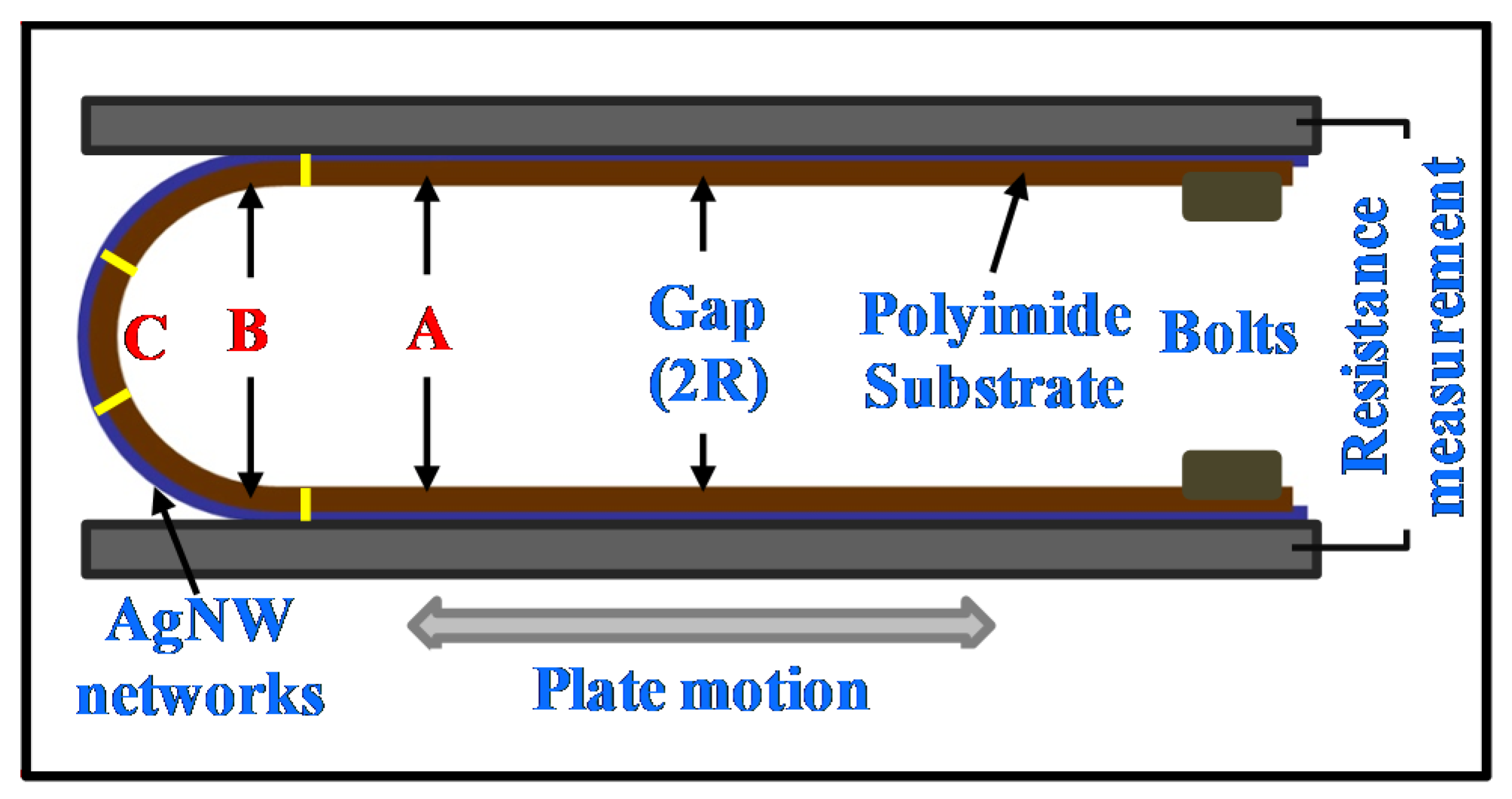
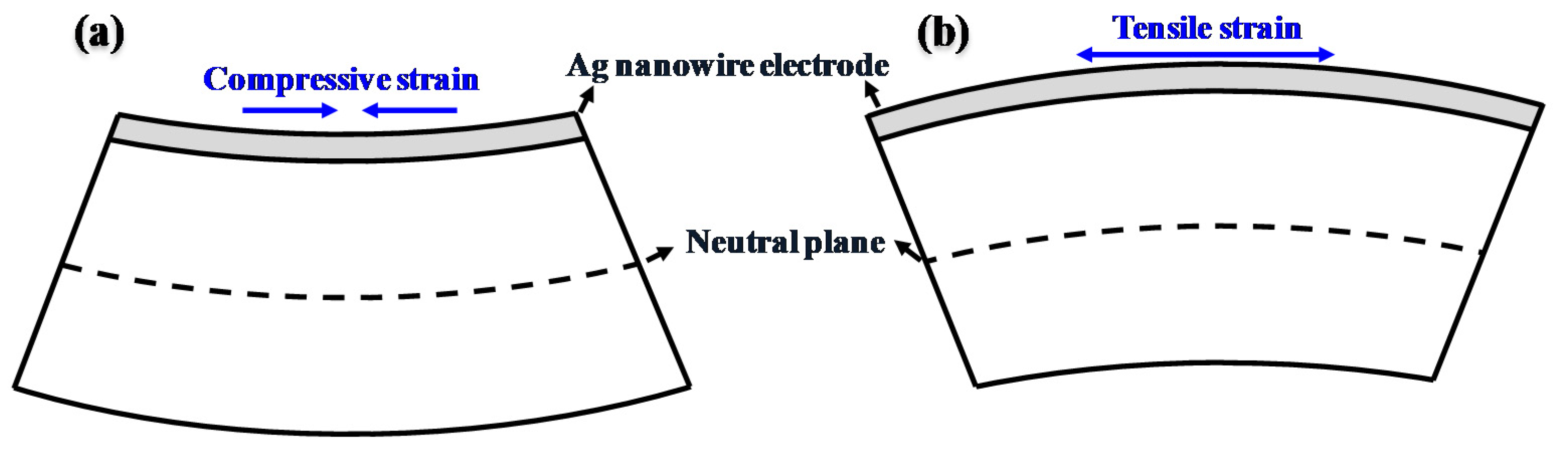
2. Concept of a Cyclic Bending Tester

Figure 1 shows a schematic of a cyclic bending tester. For cyclic bending tests, a silver nanowire network coated on a flexible substrate is fixed between the upper and bottom plates with metal screws. Strain is applied homogeneously across the sample by controlling the distance between the two plates. The strain applied to the sample is determined by the equation ε = y/R, where ε, y, and R represent the strain, the distance from the neutral plane, and the curvature, respectively. The neutral plane and the degree of deformation are determined by the thickness of the sample and the distance between the upper and lower planes, respectively. The bending strain in the sample is induced by moving the lower plate periodically from left to right. In addition, by controlling the displacement of the lower plane, the area to which the strain is applied is determined.
Due to these features of a cyclic bending tester, samples can be sectioned into three different zones: A, B, and C. Zone A refers to the strain-free region, zone B refers to the region in which repetitive strain is applied, and finally, zone C refers to the region in which constant strain exists. Since zone A is strain-free and zone C experiences constant strain, the test results for these two zones are negligible. Therefore, in the cyclic bending test, the actual result is primarily drawn in zone B where repetitive and periodic strain is applied to samples. As mentioned above, the areas of zone B and zone C are determined by the displacement of the lower plane. The edges of the upper and lower plates where the sample is fixed are covered with an electrically conductive material, such as copper or silver. Thus, fluctuations in the electric signal during cyclic bending can be collected in real time [28,29].
In summary, a cyclic bending tester can vary the speed and degree of the deformation and the area of the sample to which strain is applied. In addition, a fatigue tester can apply strain to a sample over 1,000,000 times while precisely measuring the electric signal depending on the bending cycles. Thus, various mechanical reliability tests with different deformation conditions are possible using a cyclic bending tester.

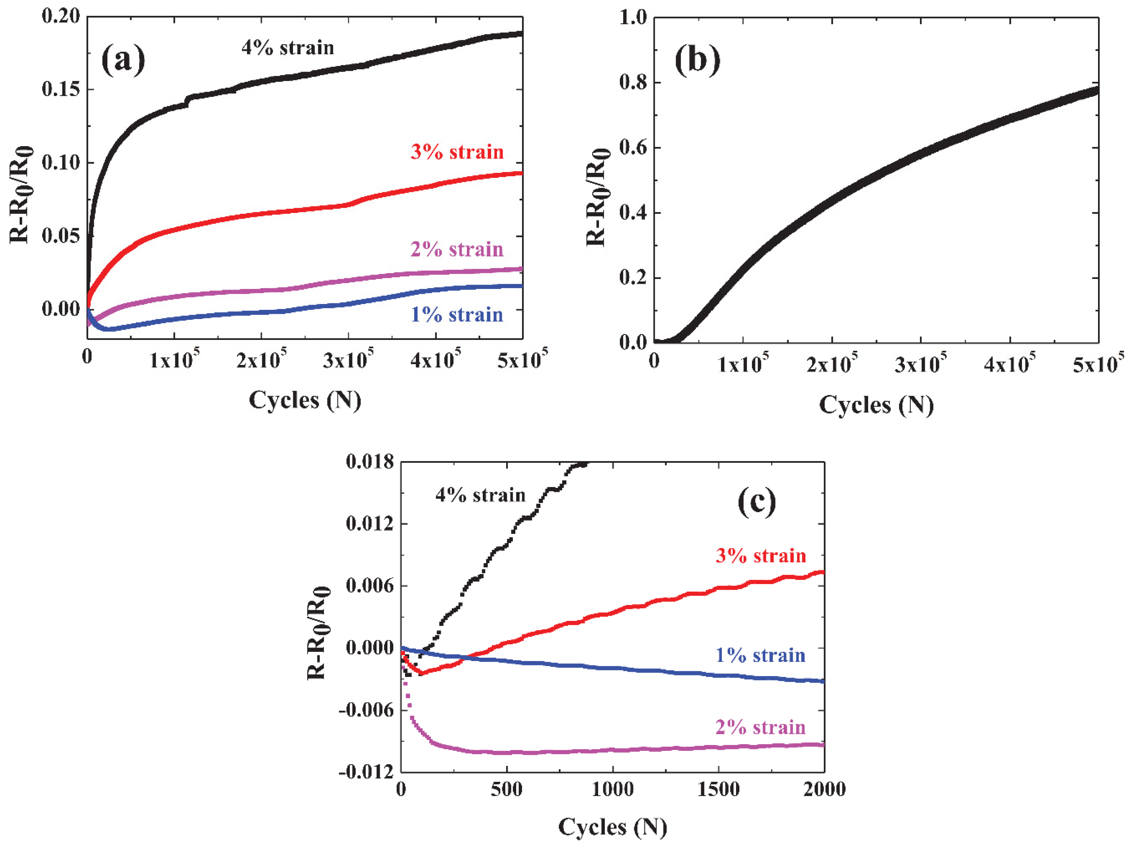
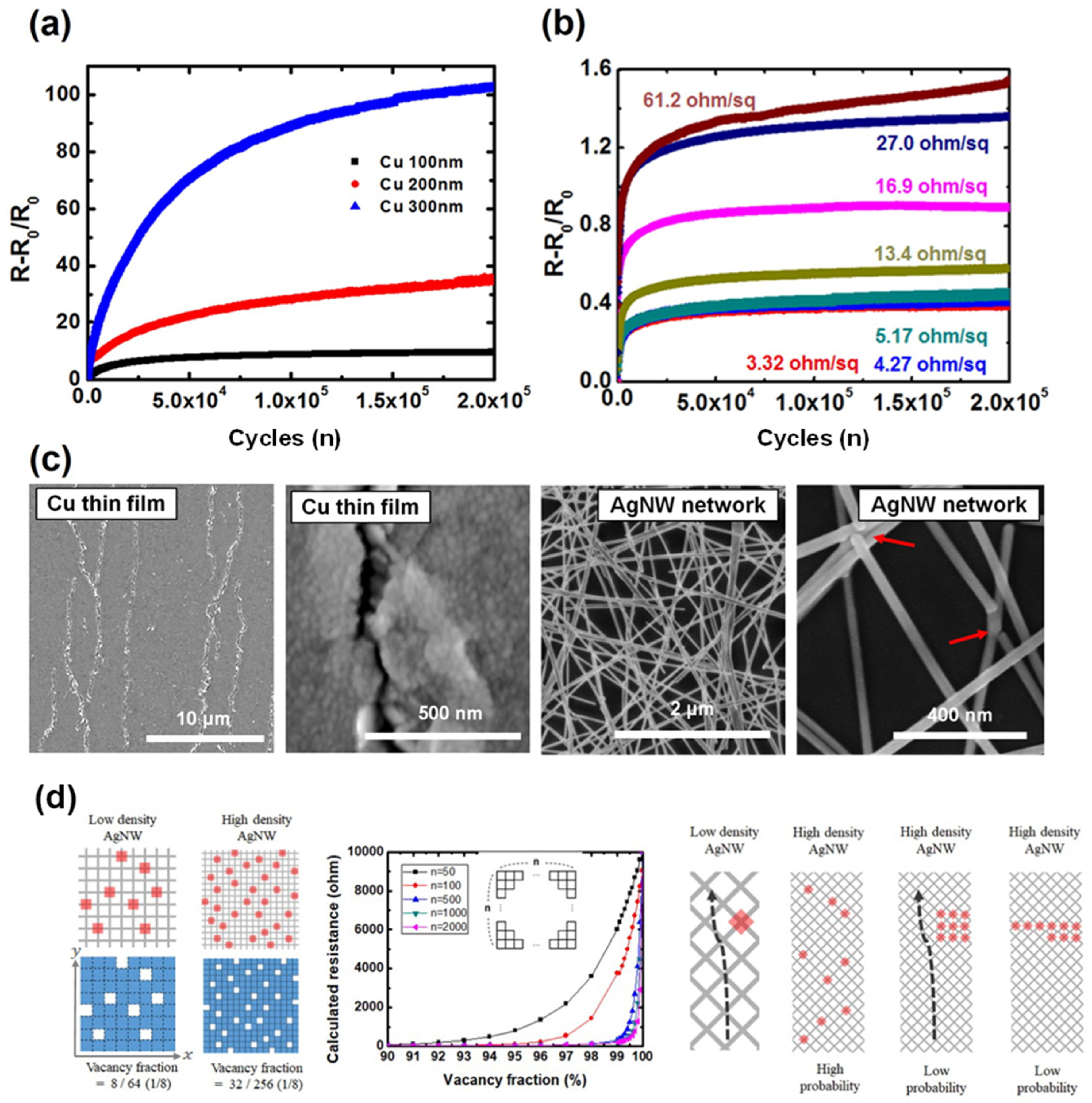
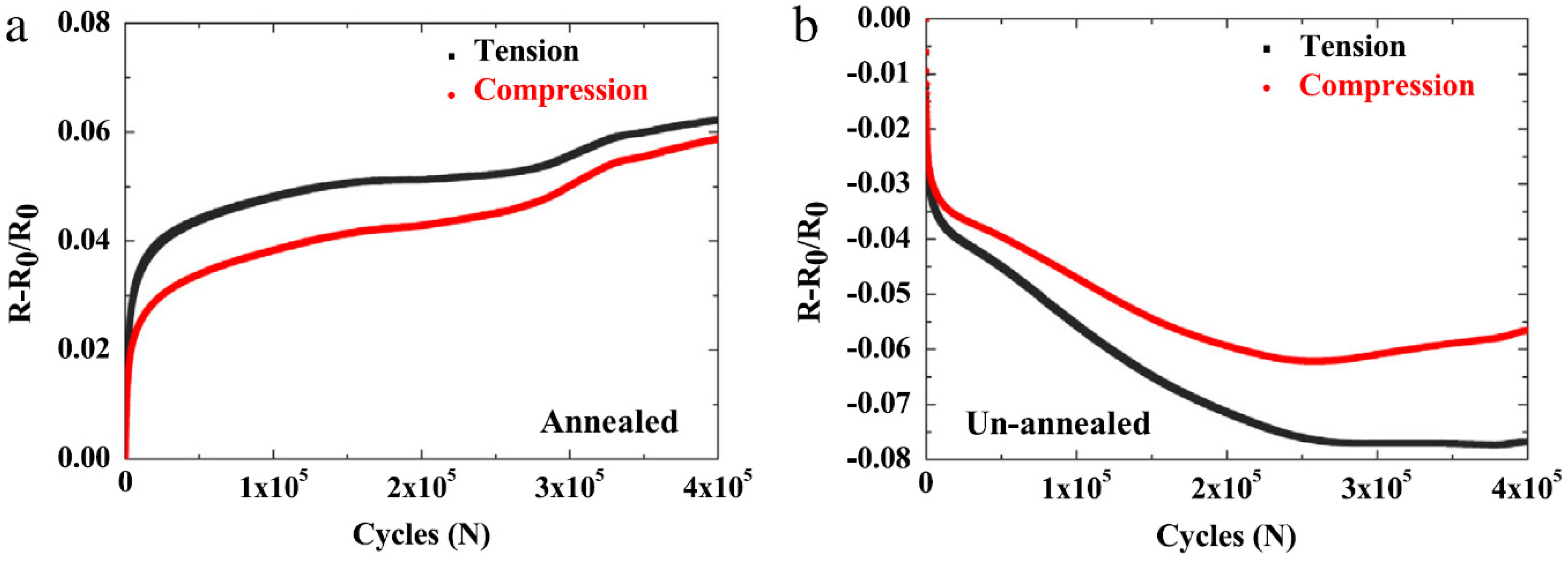
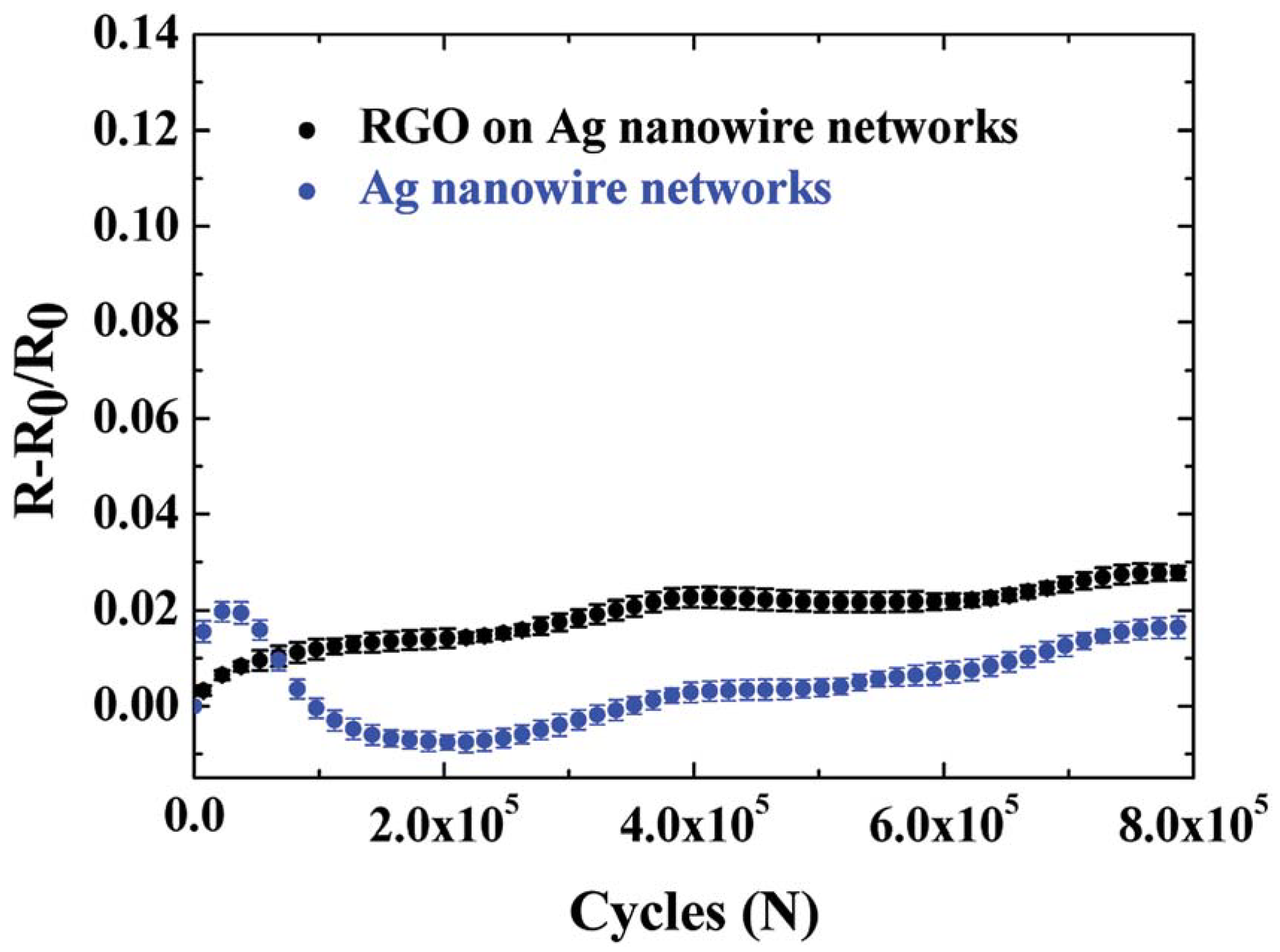
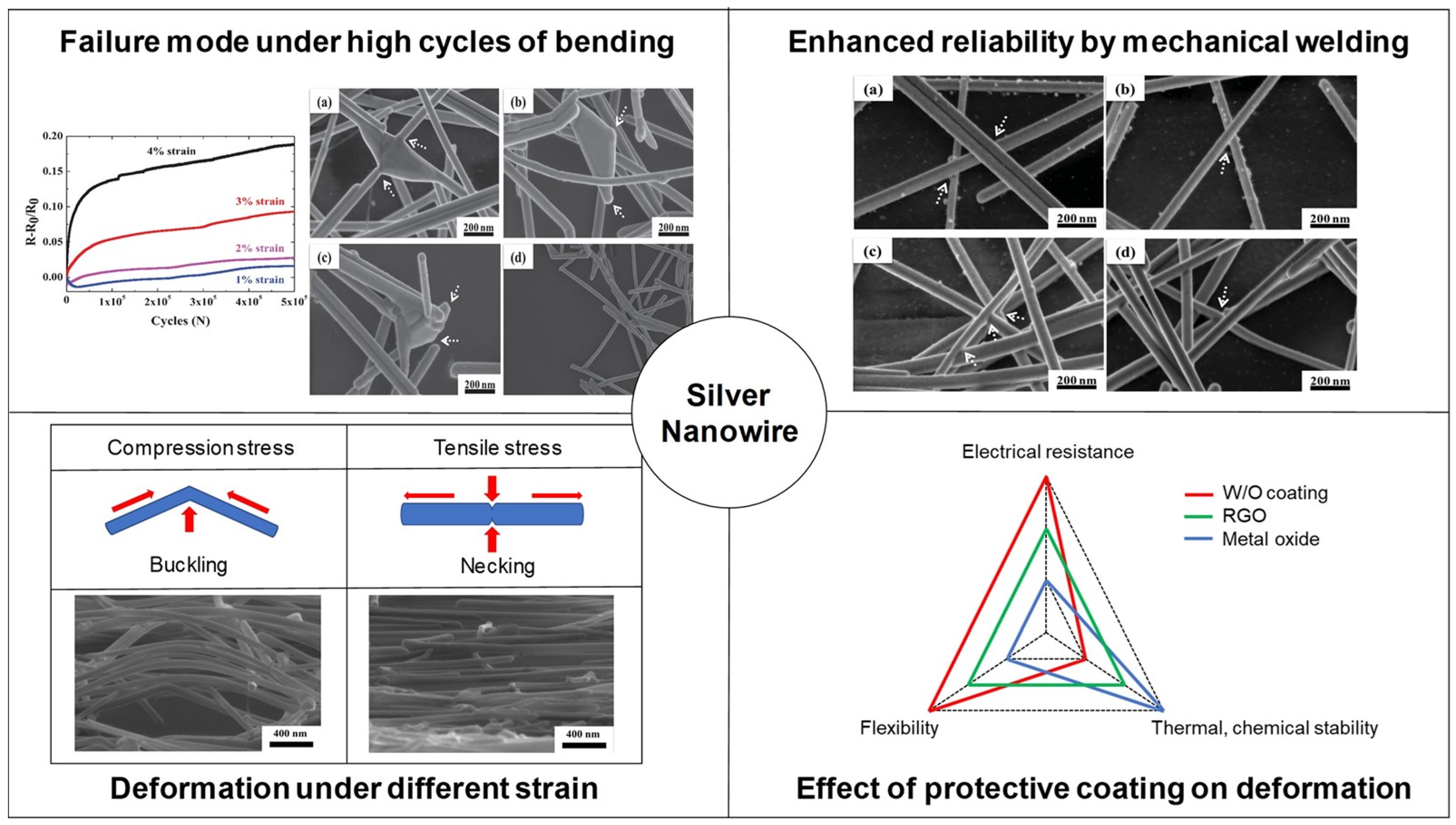
3. Deformation Behavior and Mechanical Reliability of Silver Nanowire Transparent Electrodes under Many Bending Cycles

Figure 2a shows the change in the resistance of the silver nanowire network under repetitive deformation. The x- and y-axes indicate the number of bending cycles and the increase in resistance, compared to the initial resistance, respectively. Figure 2b shows the same test results for silver thin films for comparison.
The initial resistance of the silver nanowire network was 3.2–3.6 ohm/sq and the strain applied to the sample varied at 1–4%. As more strain was applied to the samples, the change in resistance of the silver nanowire network increased accordingly. However, the resistance change in the silver nanowire network was <20% after 500,000 cycles, even with 4% strain, which was much less than that of the silver thin film or ITO film [30,31]. In the case of silver thin films with 100 nm of thickness, the resistance increased up to ~80% under only 1% strain, as shown in Figure 2b. In addition, for ITO, the increase in resistance was known to be hundreds and thousands of percent, under even 1% strain [31]. Given the fact that failure of electronics happens when the resistance change exceeds 20% of the initial resistance, the silver nanowire network showed superior mechanical reliability and potential for use in real industry.
The superior mechanical reliability of the silver nanowire network is derived from two factors. In the case of the metal thin films, dislocations accumulate on the interface between the plane and the thin film, creating the defect where the strain is concentrated and ultimately causing fatigue damage as shown in Figure 3 [32,33]. However, according to the size-dependent plasticity, the creation of dislocation is difficult in a nanowire network due to the small diameter of nanowires. Furthermore, even if dislocation is created, it easily moves to the nanowire surface, causing dislocation starvation states in the nanowire [34,35]. Due to these unique characteristics of nanowires, nanowire networks exhibit a high mechanical strength that is close to the theoretical value, referring to where the silver nanowire itself is more resistant to stress than bulk silver [36,37]. In addition, the dislocations do not accumulate at the interface between the substrate and the silver nanowire network; thus, unlike the silver thin film, cracks that result from the accumulation of dislocations at the interface are less likely to happen for a silver nanowire network, resulting in less increase in resistance [32]. The silver thin film with a thickness below the diameter of a single nanowire, approximately <35 nm, will show less increase in the resistance under cyclic bending than those with 100 nm thickness. Because the fatigue failure in the thin film is initiated by the accumulation of dislocations at the film–substrate interfaces, which are avoidable in the silver nanowire network, the silver nanowire is expected to still have better mechanical reliability than the silver thin film even with the thickness equal to the diameter of a single nanowire. However, the confirmation of the mechanical reliability of the silver thin film with a few tens of nanometers will be an interesting topic for future research.
Furthermore, the network structure itself contributes to the high mechanical reliability. As Figure 4 shows, when tensile strain is applied, the network structure deforms. As suggested in Figure 4 [38], which is a COMSOL (COMSOL Inc., Stockholm, Sweden) numerical simulation of the deformation of a silver nanowire network, tensile deformation is accommodated by the network structure, which results in large deformability. Despite the number of junctions existing between nanowires diminishing and the wires elongating, the network structure is retained and there are sufficient junctions to form an electrical percolation pathway. Furthermore, the stress applied to individual nanowires dissipates and fewer cracks are created by the deformation of the network itself. As a result, it minimizes the increase in the resistance of the silver nanowire network.
Nevertheless, a silver nanowire network shows increased resistance when it is subjected to repeated deformations. The reasons behind this increase in resistance can be explained through microstructural analysis. Silver nanowires are characterized by a polyvinylpyrrolidone (PVP) coating as a result of their fabrication process [39,40]. This thin polymer layer increases the interfacial resistance between the individual nanowires. Therefore, to reduce the interfacial resistance, a thermal annealing process for high electrical conductivity is required. Figure 5a shows that silver nanowires adhere with other silver nanowires and form thermal junctions during the thermal annealing process at 150–200 °C. Interestingly, through repetitive bending, cracks were created at junctions as a result of high stress concentration, and the crack propagation resulted in the failure of the silver nanowires, as shown in Figure 5b. As shown in Figure 5c,d, failure in the silver nanowire junctions caused the failure of nearby junctions, resulting in a serious increase in the resistance as the number of bending cycles increased. This refers to how grain boundaries tend to exist at thermally fused junctions, and individual silver nanowires and cracks were formed as a result of the focused strain on those grain boundaries.
Based on previous research, it can be presumed that a silver nanowire network without thermal junctions has better mechanical stability under repeated deformation because the strain is focused in a smaller area. Figure 6 shows the result of the cyclic bending test of the silver nanowire network without a thermal annealing process. In the un-annealed silver nanowire network, the resistance exponentially reduced as the strain increased. In addition, even after the declination of the resistance was saturated, the resistance did not increase but maintained its decreased level. Such resistance reduction was also observed for the annealed silver nanowire network at the initial bending cycles as shown in Figure 2c.
The reduction in the resistance resulted from the formation of mechanical welding between silver nanowires. As Figure 7 shows, the silver nanowires were stacked to form a sort of mechanical weld between silver nanowires. This kind of mechanical weld was formed due to the plastic deformation of the silver nanowires caused by the strain [28,41]. Similar to thermal junctions, the mechanical weld formed strain-induced adhesion between silver nanowires that provided sufficient electrical conductivity. However, unlike thermal junctions, the strain was less focused at the junctions because no grain boundaries were formed, and fewer failures occurred as a result. Therefore, it is expected that the fabrication of a silver nanowire network with higher mechanical stability is enabled by the creation of mechanical welds between silver nanowires.
Park et al. studied the resistance increase in the silver nanowire electrode during bending fatigue testing as a function of the density of the nanowire network and compared this against the behavior commonly observed in a Cu thin film electrode [42]. The silver nanowire network showed a smaller increase in fractional resistance (∆R/R) with an increase in the density of the network during cyclic bending; hence, the dense silver nanowire network is more reliable as shown in Figure 8b. Cu thin films showed the opposite trend of enhanced reliability for thinner films (Figure 8a). The opposite trend in the effect of thickness or density variation in the silver nanowire network can be understood by considering the electrical percolation behavior of a network. First, it was noted that the silver nanowire network results in the random distribution of failures at the junctions (point-type failure), where the Cu film results in fatigue-induced line crack propagation perpendicular to the bending direction (Figure 8c). The failure in the silver nanowire network was modeled as a grid to numerically calculate the expected resistance for high- and low-density networks, which indicates smaller ∆R/R for a higher network density because more electrical pathways are present, as shown in Figure 8d.

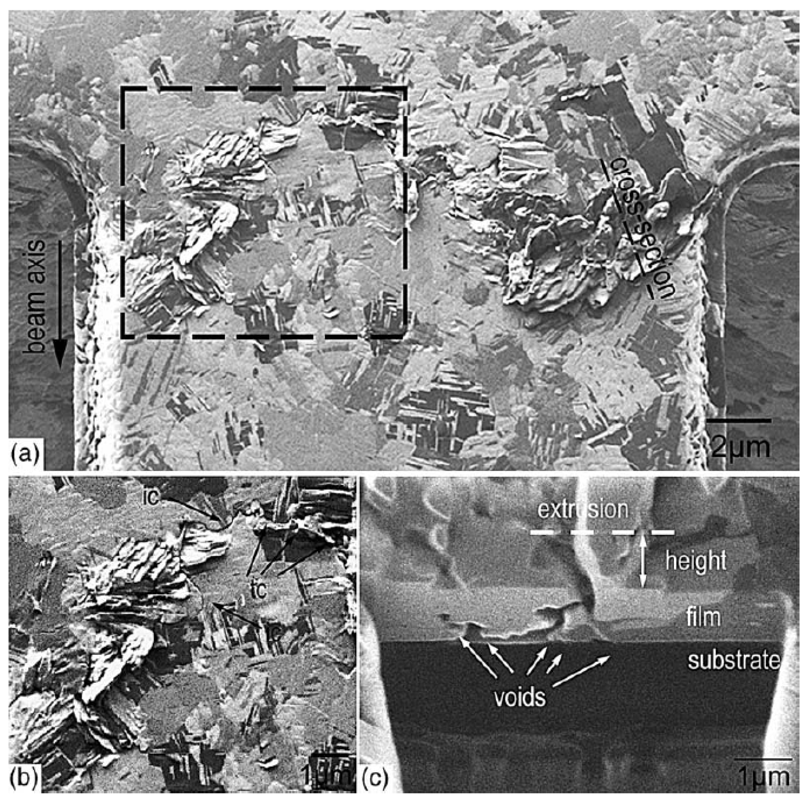
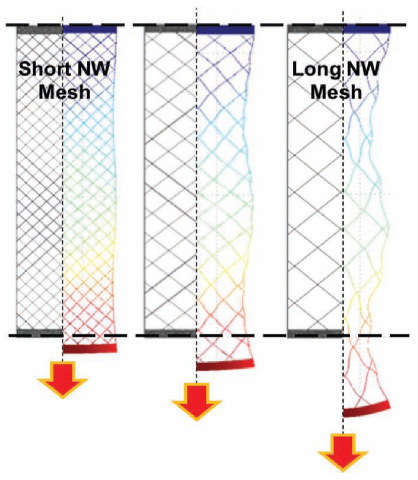
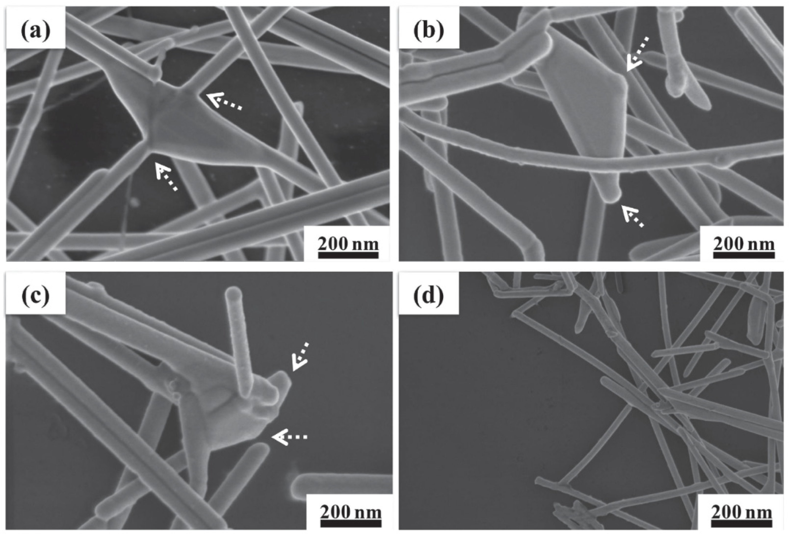
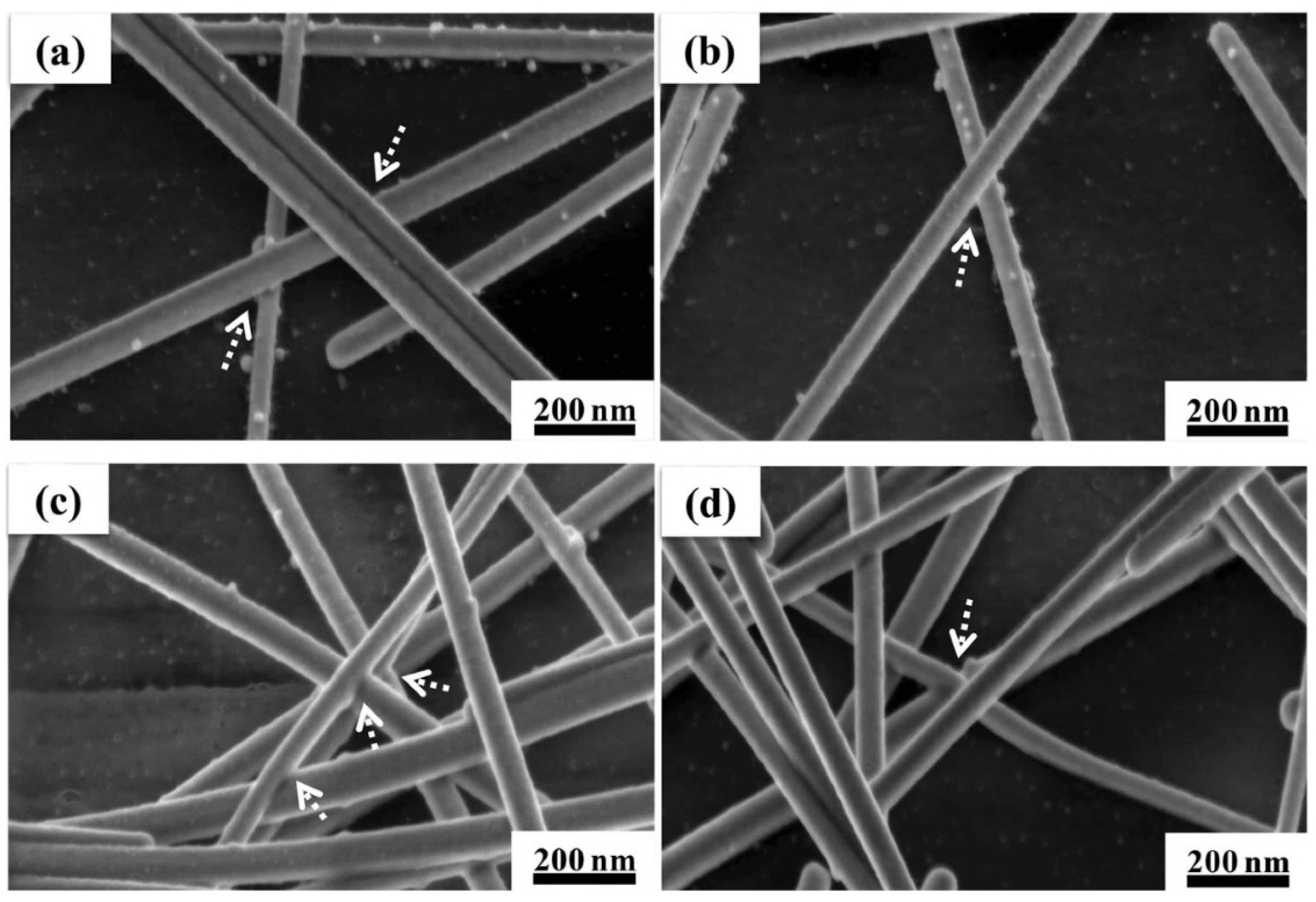
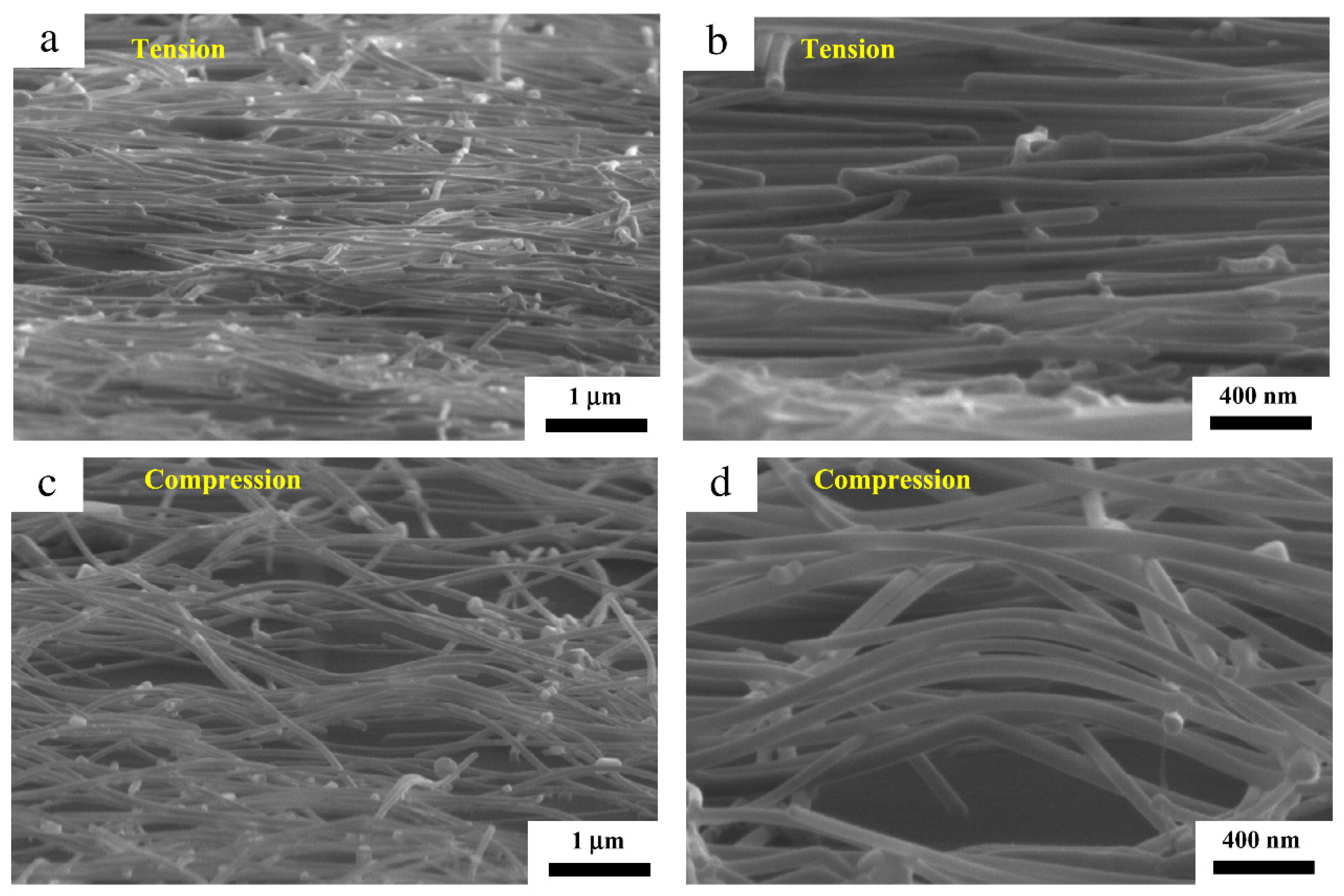
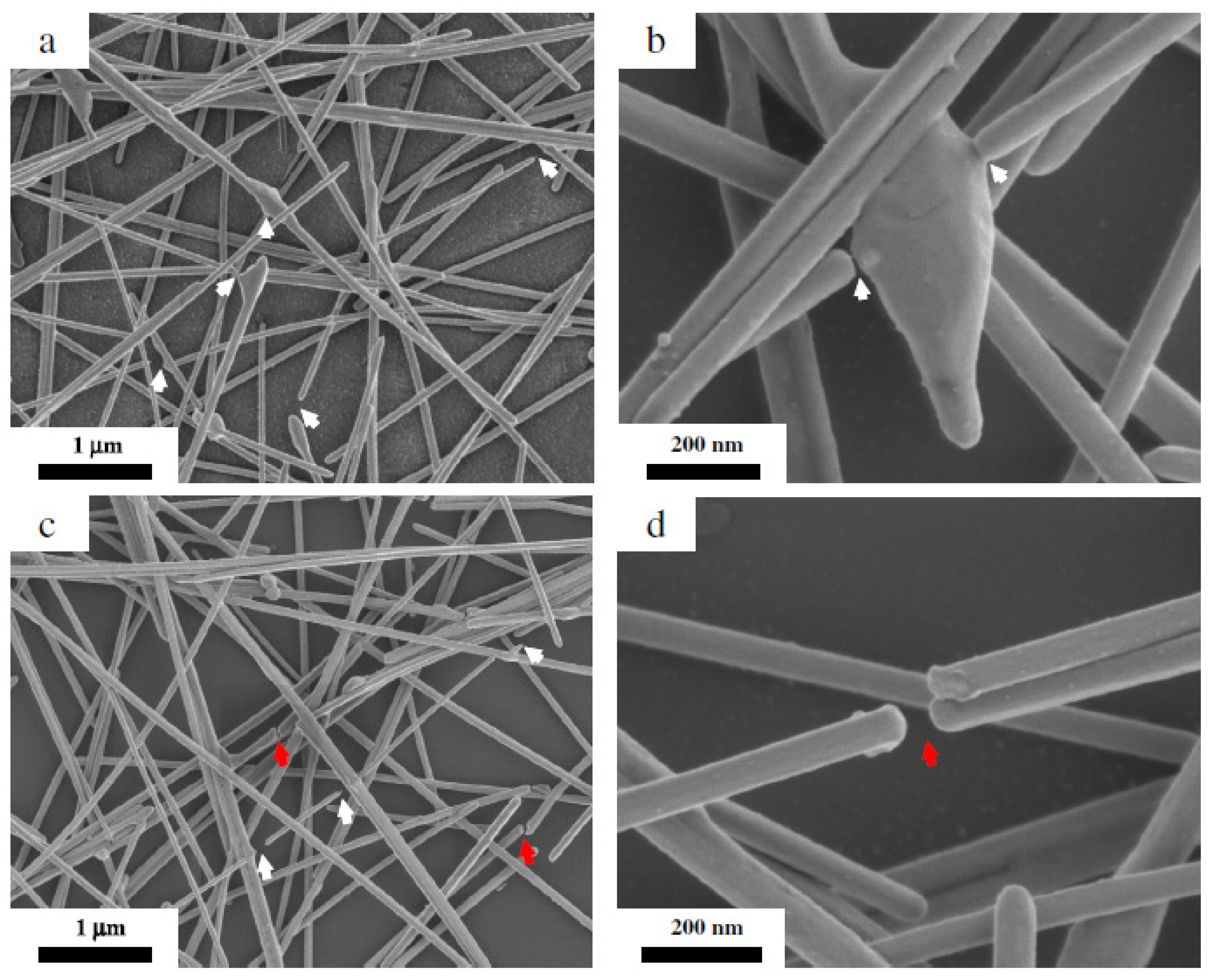
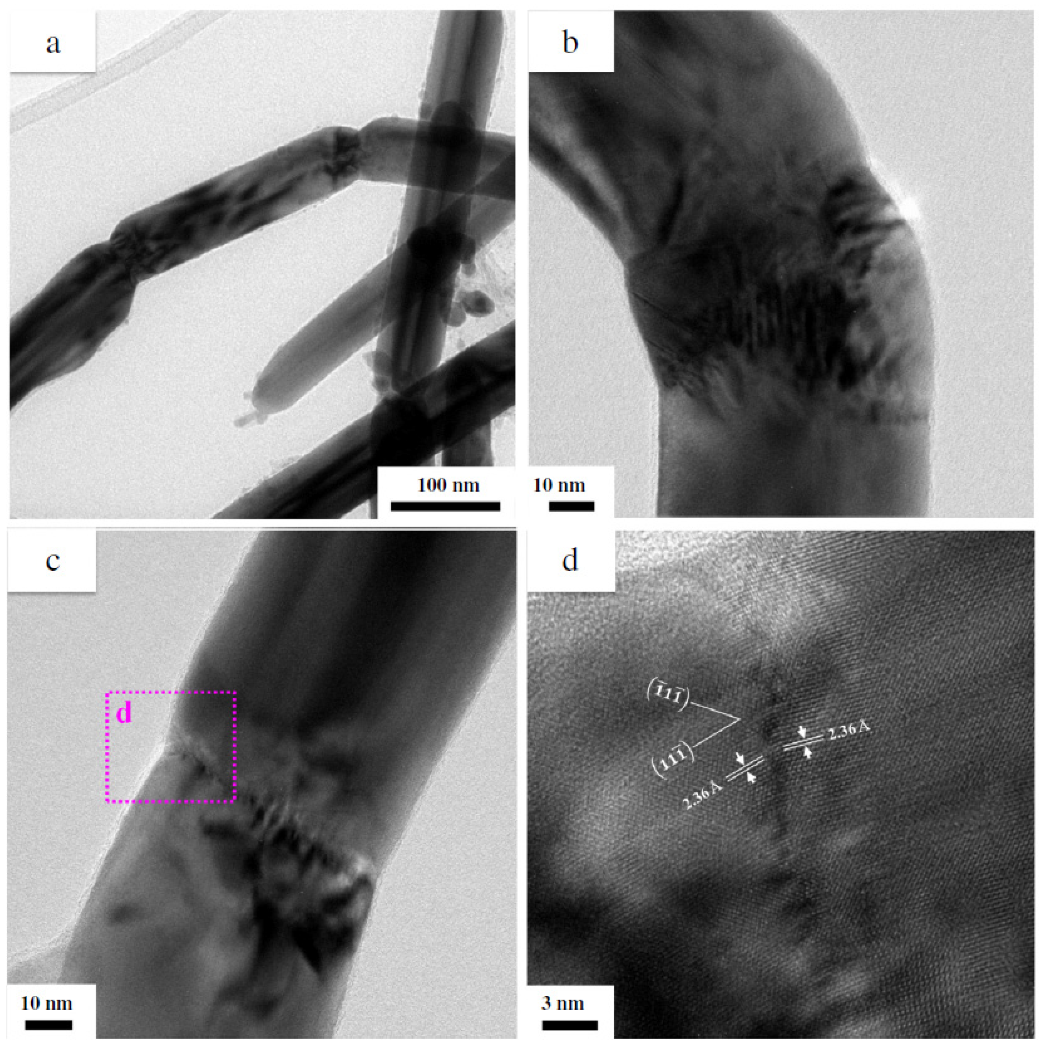
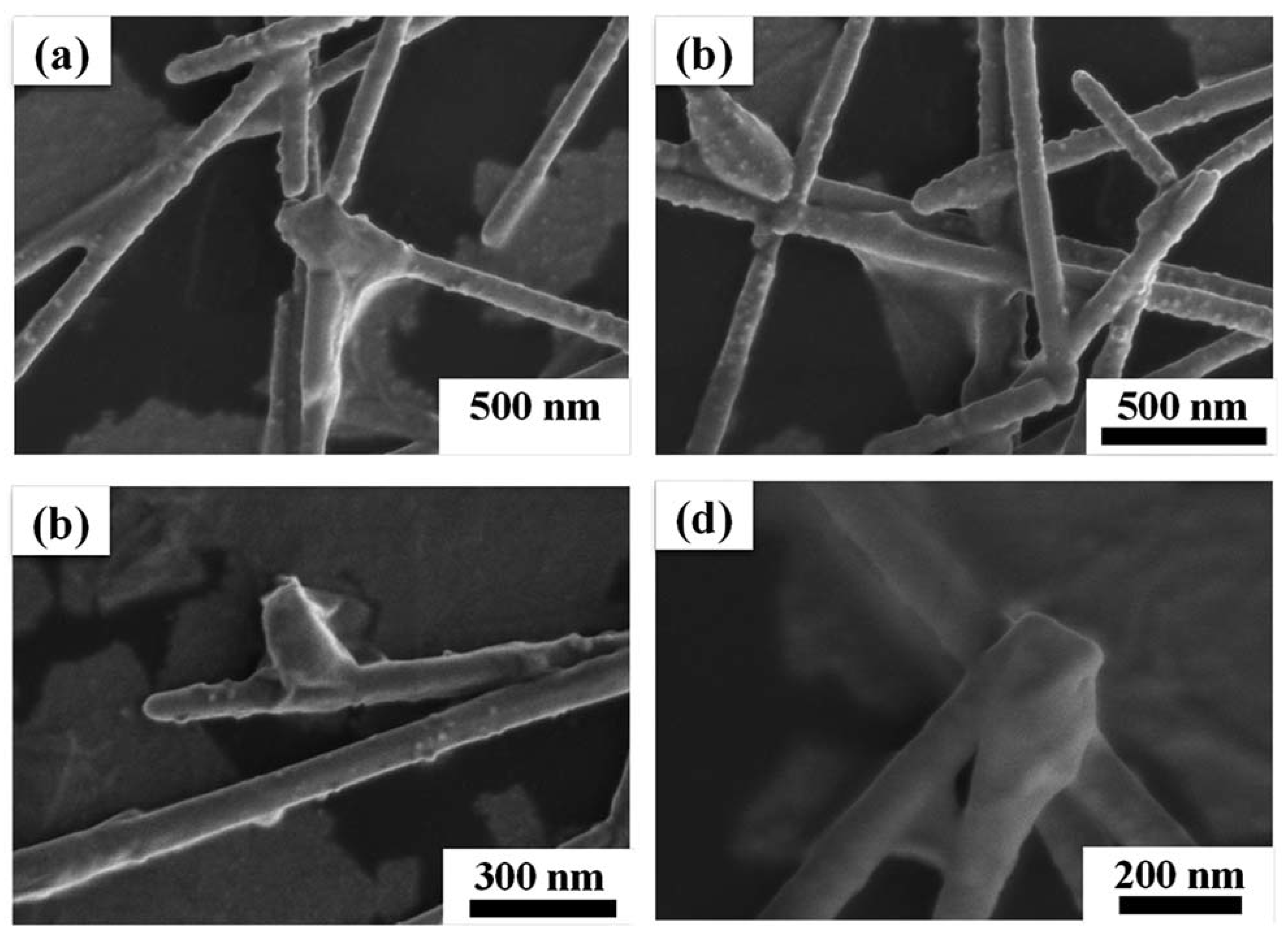
4. Deformation Mechanism of Silver Nanowire Network under Various Deformations

The interesting point about the silver nanowire network is the differences in the deformation mechanism according to the type of deformation. As Figure 9 indicates, compression stress was applied to a silver nanowire network when the network was positioned close to the center of the curvature (Figure 9a). By contrast, tensile stress was applied to the silver nanowire network when it was located away from the center of the curvature (Figure 9b). The amount of stress applied to the silver nanowire network was independent of the type of stress as far as the network was located from the same distance from the neutral plane.
The results of the cyclic bending test in Figure 10 show that the increase in resistance was dependent on the bending condition. Four hundred thousand bending cycles with a strain of 2.5% were imposed while measuring the in situ resistance. Even though the amount of stress was the same, the increase in the resistance of the silver nanowire network was higher for tensile bending than for compressive bending. In the case of the un-annealed silver nanowire network, the decrease in the resistance was higher when tensile bending was applied to those samples, indicating that the tensile strain causes a larger deformation than the compressive strain (Figure 10).
This difference in the resistance change behavior depending on the stress type resulted from the differences in the deformation mechanism between the compressive force and tensile force. As Figure 11 shows, the silver nanowires extended along the direction of the tensile force, whereas buckling occurred for silver nanowires exposed to compressive strain. Owing to the buckling, stress was dispersed across the network and fewer failures occurred for silver nanowires under compressive strain. In addition, the buckling resulted in failure along the length of individual nanowires (Figure 12c,d), unlike the silver nanowire networks under tensile bending for which the failure occurred at the junction (Figure 12a,b). The different failure under compressive strain was due to the stress localization at the sub-grain boundaries formed by buckling as shown in Figure 13. Therefore, even if the sample was exposed to the same amount of strain, a smaller change in the resistance occurred for the compressive strain. This implies that silver nanowires show different deformation mechanisms under different types of strain; thus, different design factors should be applied depending on the status of stress imposed on the silver nanowire networks.

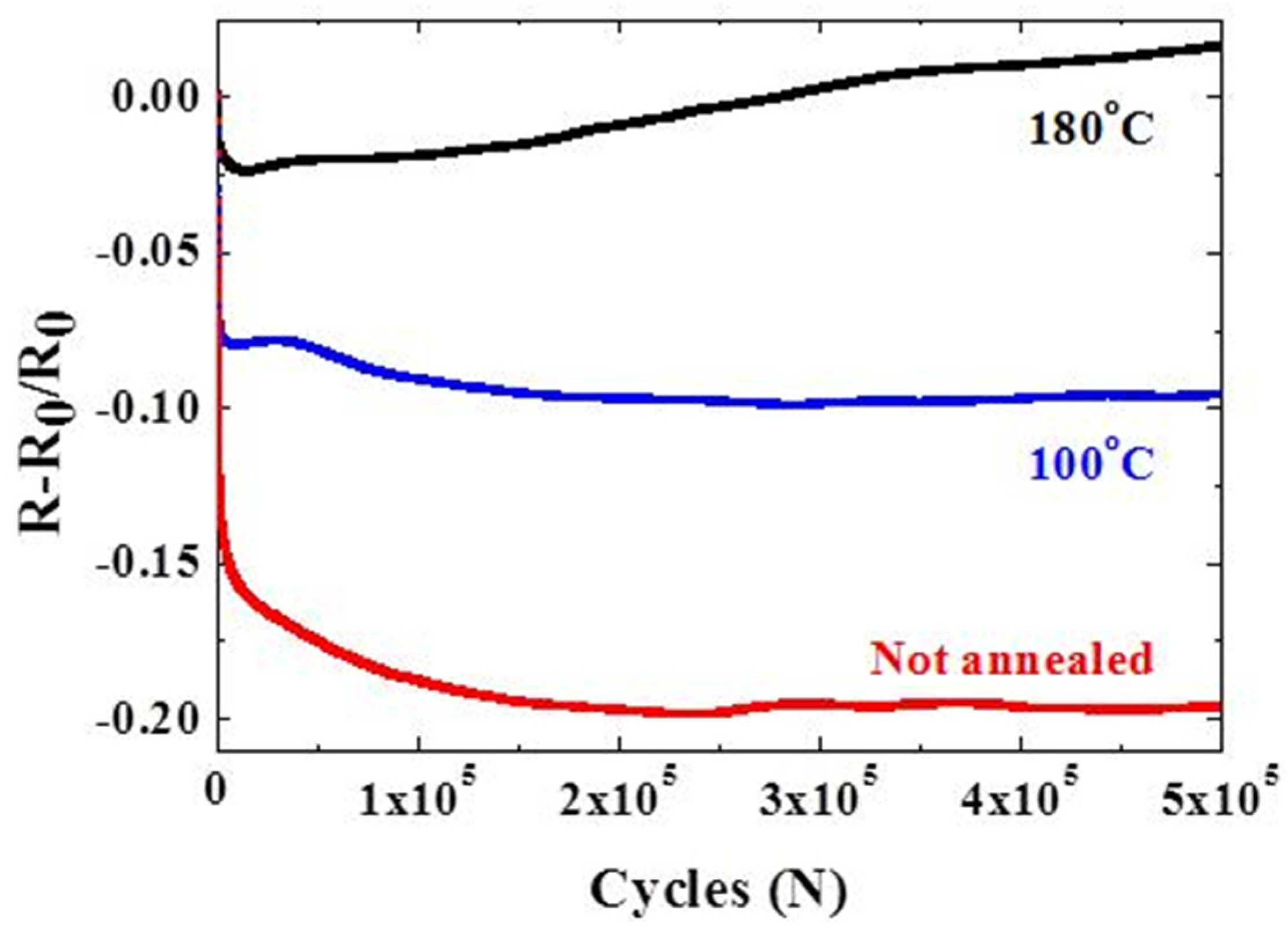
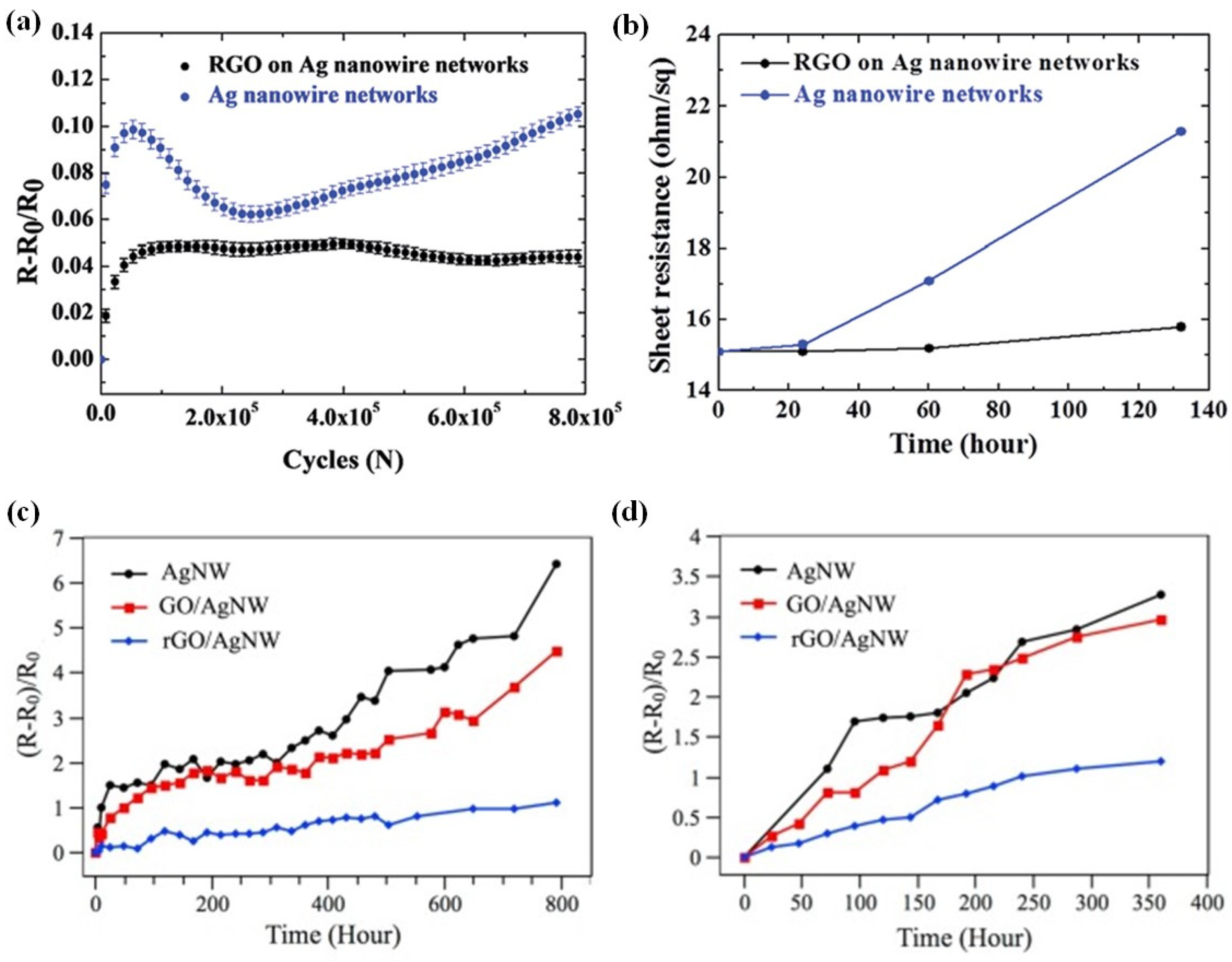
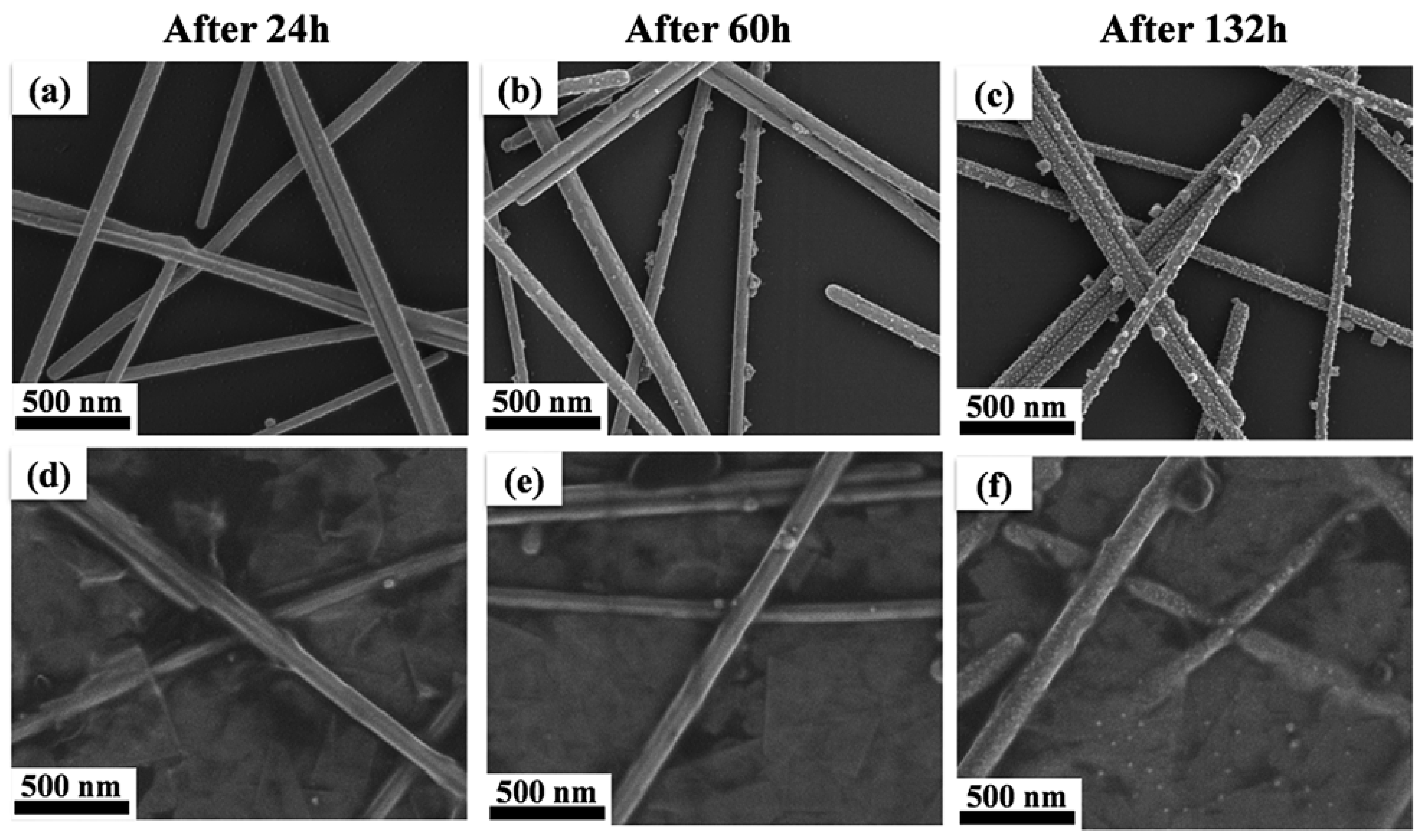
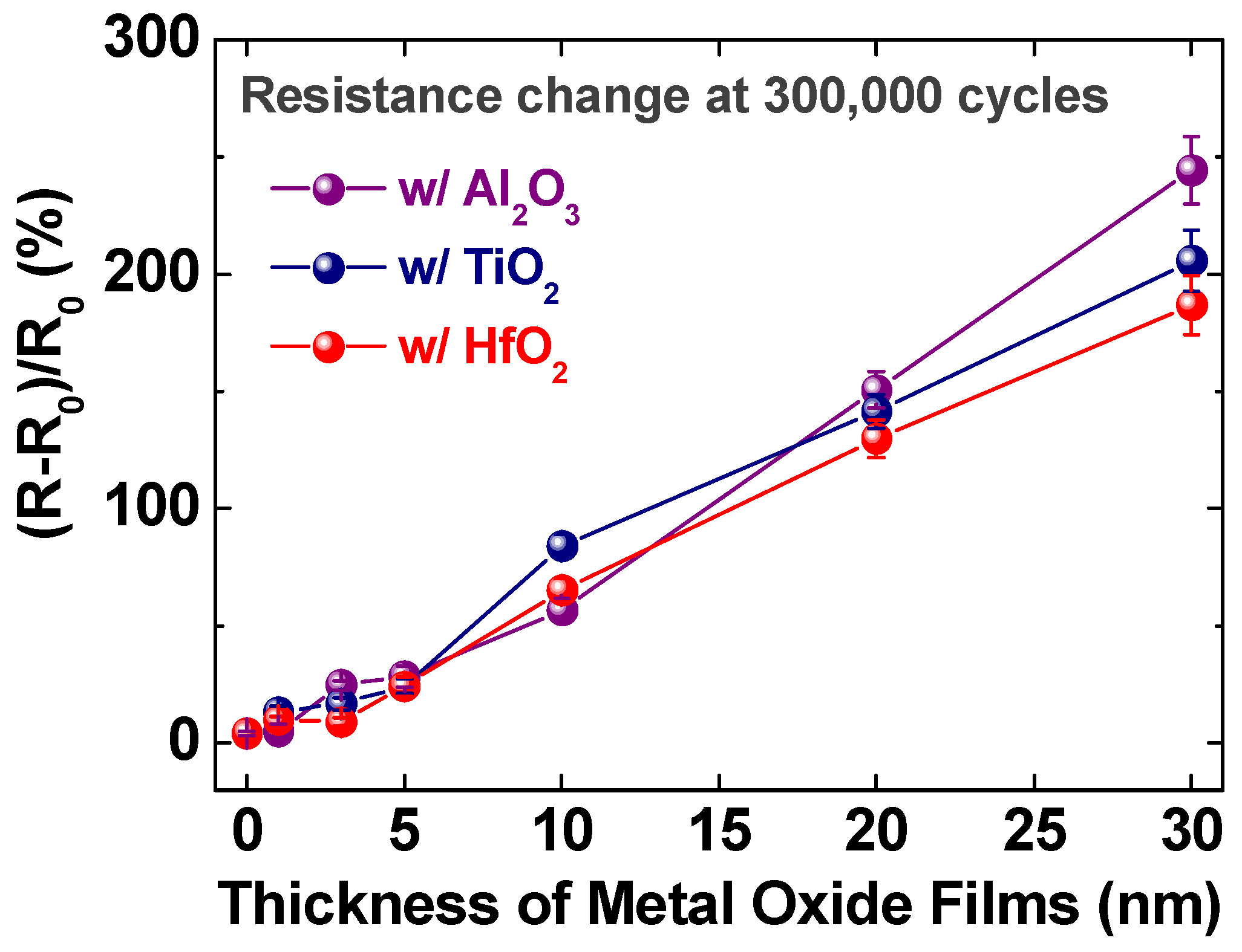
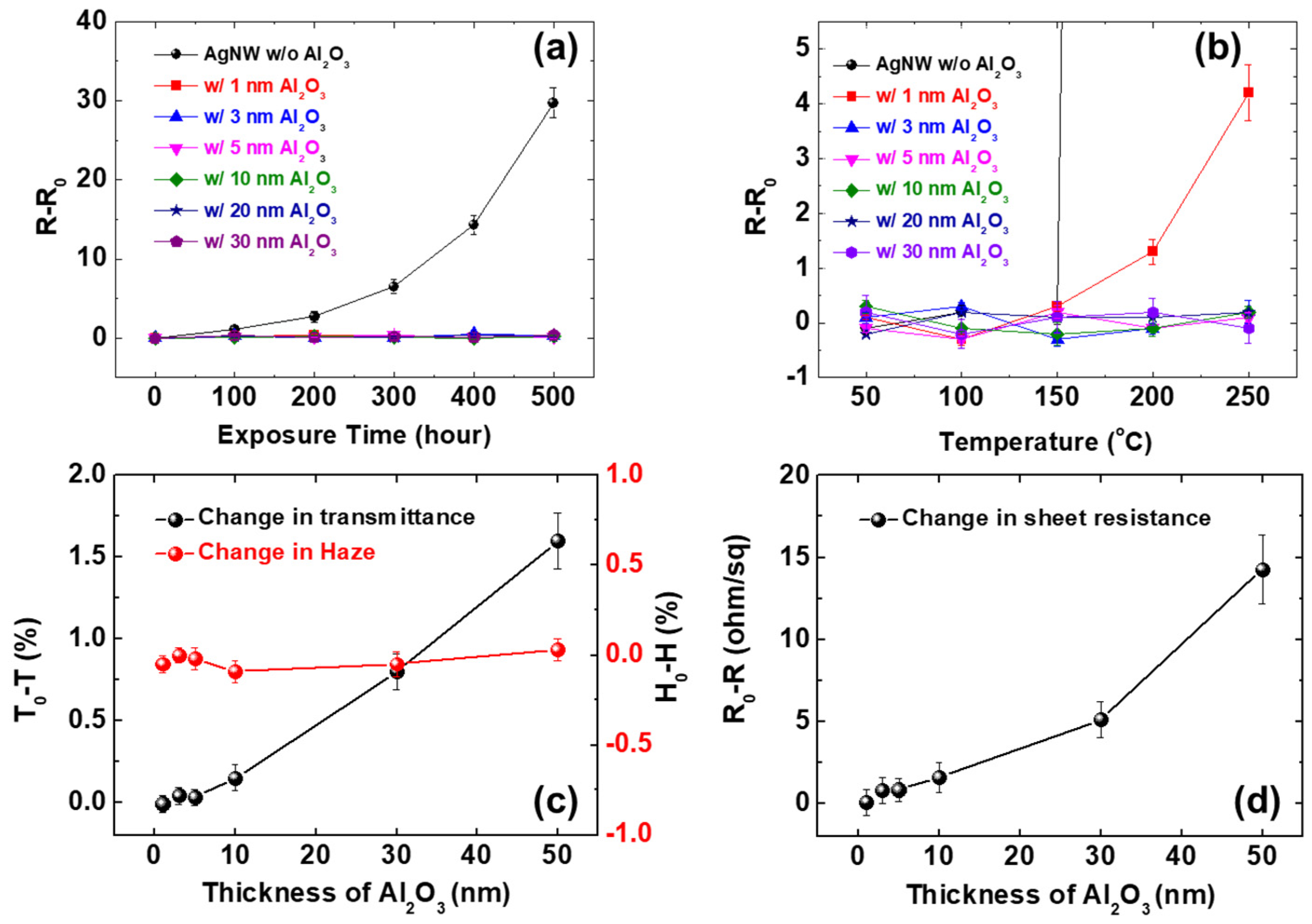
5. Deformation Behavior of Silver Nanowire Network with Protective Coating

Silver nanowires are vulnerable to oxidation and high temperatures [24]. To overcome these limitations, various studies have attempted to coat materials with good thermal, electrical, and chemical properties on silver nanowire networks to protect them [44,45]. Among candidates for coating materials, reduced graphene oxide (RGO) coating is emerging as a method to improve the chemical stability of silver nanowires [46]. RGO can be prepared easily by exfoliating graphite and, similar to the graphene, it is used as a passivation layer to prevent the oxidation of metals [45,47]. In addition, good electrical conductivity makes RGO a promising material [48]. Despite the good chemical and electrical properties of coating materials, the mechanical stability of a silver nanowire can be affected as it combines with other materials to form hybrids. Thus, investigation of the mechanical reliability of protective-material–silver-nanowire hybrids should be conducted; in the following, the mechanical stability of the RGO-coated silver nanowire network under repeated deformation testing, using a cyclic bending tester, is discussed.
Figure 14 is the result of cyclic bending tests of the RGO-coated silver nanowire network. After repeated bending for over 800,000 cycles at 1.5% strain, the change in the resistance of the silver nanowire network with and without RGO showed a small difference. As shown in the SEM images of the RGO-coated silver nanowire network after cyclic bending (Figure 15), the microstructure of the samples with and without RGO coating showed similar results that failures occurred at thermally fused junctions. This refers to how the deformation mechanisms of the silver nanowire networks with and without RGO coatings were similar. In addition, the presence of RGO without forming strong bonds between silver nanowires had a negligible effect on the change in the deformation mechanism of the silver nanowire network. This resulted from the additional, electrically conductive pathway provided by the dispersion of RGO on the silver nanowire. Therefore, the decrease in the resistance was harder to observe for the RGO-coated silver nanowire network due to the larger, electrically conductive pathway.
The cyclic bending test of the oxidized silver nanowire network demonstrated that the RGO-coated silver nanowire network had a smaller increase in the fractional resistance, as shown in Figure 16a. Exposing the RGO-coated silver nanowire and bare silver nanowire network to air at 70 °C for 132 h oxidized both the silver nanowire networks. However, the SEM image of the bare silver nanowire network in Figure 17 shows the prominent formation of oxides on the surface of the network as it was further exposed to ambient air at an elevated temperature. Such formation of oxides increased the sheet resistance of the silver nanowire networks; thus, the bare silver nanowire networks showed a much higher increase in resistance during the exposure to air at 70 °C than silver nanowire networks with RGO coating as shown in Figure 16b. Such enhancement of chemical stability by the RGO coating was also confirmed in the work by Li et al., where, compared with that of the bare silver nanowires, the increase in the resistance of the silver nanowire electrodes with RGO coating was much lower when exposed to air at 120 °C (Figure 16c) and at 85 °C with 85% relative humidity (Figure 16d) [50].
The native brittleness of oxide and concentration of the stress around the oxide resulted in several failures in the network [51]. Furthermore, the formation of silver oxide, which has a higher resistivity than pure silver, hinders the electrical conduction within the network and reduces the area of the electric percolation pathway [38]. Thus, a smaller increase in the fraction resistance of the RGO-coated silver nanowire network is in line with lesser oxidation of the silver nanowire network.
As demonstrated above, coating the silver nanowire network with RGO did not affect its deformation behavior, but increased the chemical stability against oxidation and ultimately increased the network’s mechanical reliability. Therefore, combining RGO with a silver nanowire network seemed a promising method to fabricate a mechanically reliable silver nanowire network.
Metal oxide is another example for the protective coating to enhance the chemical and thermal stabilities of silver nanowire electrodes [52,53,54,55,56,57]. Lee et al. investigated the effect of a metal oxide coating on the fracture behavior of silver nanowire networks [52]. Al2O3, HfO2, and TiO2 films were deposited on silver nanowire electrodes by atomic layer deposition at a low temperature of 100 °C. Cyclic bending tests with in situ resistance measurements were conducted for up to 300,000 cycles. Thicker metal oxide films resulted in a greater increase in the resistance of composite electrodes under cyclic bending, owing to the reduced fracture strength of thicker films as shown in Figure 18. Regardless of the type of metal oxides, however, a similar tendency of resistance change in response to cyclic bending was observed, which revealed that the critical thickness calculation based on Griffith’s theory for the evaluation of the brittle-to-ductile transition was not applicable. Damaged Al2O3-coated silver nanowire composite electrodes sustained excellent chemical stability without showing an increase in resistance, even after 500 h of exposure at 85 °C (Figure 19a). Regarding the thermal stability, the damaged silver nanowire composite electrode with a 1 nm Al2O3 film showed an increased sheet resistance at 200 °C. The other damaged samples with Al2O3 layers thicker than 3 nm showed excellent stability up to the maximum test temperature of 250 °C (Figure 19b). The analysis of the optoelectronic properties revealed that silver nanowires with Al2O3 layers thicker than 5 nm showed the degradation of the optical transmittance due to increased light reflection at the film–substrate interfaces (Figure 19c). Based on the mechanical, thermal, and chemical stability test results, the optimized Al2O3 thickness for flexible silver nanowire composite electrodes was proposed as 3–5 nm (Figure 19d).

6. Conclusions

In summary, silver nanowire electrodes showed considerably better reliability, compared to the competitors, such as ITO or Ag thin films, under a high number of bending cycles. Such excellent mechanical reliability was secured even after applying protective layers, such as RGO or metal oxides, on the silver nanowires. Thus, the resistance increase in silver nanowire-based electrodes under a high number of bending cycles was much lower than that of ITO or silver thin films, as summarized in Table 1. The enhanced mechanical reliability was due to the different deformation behavior of silver nanowire electrodes from that of the thin film-type materials, where dislocation accumulation at the substrate–nanowire interface is difficult to form, which suppresses the crack initiation/propagation. In addition, the silver nanowire network has the geometrical advantage in that it can accommodate the imposed strain by stretching its structure. In addition, to provide in-depth insight of the deformation behavior of silver nanowire electrodes under high-cycle bending, the following critical points were discussed through this review as described in Figure 20: (1) the failure mode of silver nanowires under high-cycle bending, (2) enhanced reliability by the mechanical welding of silver nanowires, (3) the deformation mode change under different strains of tension and compression, and (4) the effect of protective coating on the mechanical reliability of silver nanowire electrodes.
As discussed above, silver nanowires have attracted significant attention for application as transparent electrodes of flexible electronic devices. The different deformation mechanisms in nanosized wires require an in-depth study of the deformation behavior of silver nanowire electrodes. In particular, understanding the deformation mechanism of materials in repetitive and various types of deformation should precede their application in real-life electronics, which must be resilient against various types of deformation and millions of repetitions of deformation. Although various research results in the complex deformation behavior of silver nanowire electrodes have been reported, as highlighted in this review, some unrevealed areas remain, such as the in situ observation of the deformation behavior of silver nanowire networks under bending or observation of crack initiation at the oxidized nanowire surface. In addition, studies on the properties of silver nanowires, such as electromigration of single nanowires or surface reaction at the surface of single nanowires with different gases, are limited. With the fundamental studies of silver nanowires, the intensive study on the applications of silver nanowires to various areas, such as electronics or energy-related fields, will accelerate the realization of flexible devices in our daily life.

Author Contributions

Data curation, Y.S., H.H. and B.H.; formal analysis, Y.S., H.H. and B.H.; funding acquisition, B.H.; investigation, Y.S., H.H., P.M. and B.H.; project administration, P.M. and B.H.; resources, P.M. and B.H.; supervision B.H.; writing—original draft, Y.S., H.H., P.M. and B.H. All authors have read and agreed to the published version of the manuscript.

Funding

This work was supported by a National Research Foundation of Korea (NRF) grant funded by the Korean government (MSIT) (Nos. NRF-2019K1A3A1A25000230 and NRF-2019K1A3A1A47000624). P.M. acknowledges support from the Ministry of Foreign Affairs and International Cooperation of Italy (MAECI) through the “Development of a cost-effective wearable metal nanowire-based chip sensor for optical monitoring of metabolites in sweat” DESWEAT Project (No. KR19GR08) funded within the framework of the Executive Program of Scientific and Technological Cooperation between the Italian Republic and the Korean Republic 2019–2021.

Acknowledgments

This work was supported by a grant of the National Research Foundation of Korea (NRF), funded by the Korean government (MSIT) (Nos. NRF-2019K1A3A1A25000230 and NRF- NRF-2019K1A3A1A47000624). P.M. acknowledges support from the Ministry of Foreign Affairs and International Cooperation of Italy (MAECI) through the “Development of a cost-effective wearable metal nanowire-based chip sensor for optical monitoring of metabolites in sweat” DESWEAT Project (No. KR19GR08) funded within the framework of the Executive Program of Scientific and Technological Cooperation between the Italian Republic and the Korean Republic 2019–2021.

Conflicts of Interest

The authors declare no conflict of interest.

References

  1. Lewis, J.; Grego, S.; Chalamala, B.; Vick, E.; Temple, D. Highly flexible transparent electrodes for organic light-emitting diode-based displays. Appl. Phys. Lett. 2004, 85, 3450–3452. [Google Scholar] [CrossRef]
  2. Madaria, A.R.; Kumar, A.; Ishikawa, F.N.; Zhou, C. Uniform, highly conductive, and patterned transparent films of a percolating silver nanowire network on rigid and flexible substrates using a dry transfer technique. Nano Res. 2010, 3, 564–573. [Google Scholar] [CrossRef] [Green Version]
  3. Sierros, K.A.; Morris, N.J.; Ramji, K.; Cairns, D.R. Stress–corrosion cracking of indium tin oxide coated polyethylene terephthalate for flexible optoelectronic devices. Thin Solid Film. 2009, 517, 2590–2595. [Google Scholar] [CrossRef]
  4. Chen, Z.; Cotterell, B.; Wang, W. The fracture of brittle thin films on compliant substrates in flexible displays. Eng. Fract. Mech. 2002, 69, 597–603. [Google Scholar] [CrossRef]
  5. Lee, J.-E.; Kim, H.-K. Self-cleanable, waterproof, transparent, and flexible Ag networks covered by hydrophobic polytetrafluoroethylene for multi-functional flexible thin film heaters. Sci. Rep. 2019, 9, 1–11. [Google Scholar] [CrossRef]
  6. Ok, K.-H.; Kim, J.; Park, S.-R.; Kim, Y.; Lee, C.-J.; Hong, S.-J.; Kwak, M.-G.; Kim, N.; Han, C.J.; Kim, J.-W. Ultra-thin and smooth transparent electrode for flexible and leakage-free organic light-emitting diodes. Sci. Rep. 2015, 5, 1–8. [Google Scholar] [CrossRef] [Green Version]
  7. Kim, S.; Yun, T.-G.; Kang, C.; Son, M.-J.; Kang, J.-G.; Kim, I.-H.; Lee, H.-J.; An, C.-H.; Hwang, B. Facile fabrication of paper-based silver nanostructure electrodes for flexible printed energy storage system. Mater. Des. 2018, 151, 1–7. [Google Scholar] [CrossRef]
  8. Kim, C.-L.; Jung, C.-W.; Oh, Y.-J.; Kim, D.-E. A highly flexible transparent conductive electrode based on nanomaterials. NPG Asia Mater. 2017, 9, e438. [Google Scholar] [CrossRef]
  9. Rowell, M.W.; Topinka, M.A.; McGehee, M.D.; Prall, H.-J.; Dennler, G.; Sariciftci, N.S.; Hu, L.; Gruner, G. Organic solar cells with carbon nanotube network electrodes. Appl. Phys. Lett. 2006, 88, 233506. [Google Scholar] [CrossRef] [Green Version]
  10. Zhang, D.; Ryu, K.; Liu, X.; Polikarpov, E.; Ly, J.; Tompson, M.E.; Zhou, C. Transparent, conductive, and flexible carbon nanotube films and their application in organic light-emitting diodes. Nano Lett. 2006, 6, 1880–1886. [Google Scholar] [CrossRef]
  11. Wu, J.; Agrawal, M.; Becerril, H.A.; Bao, Z.; Liu, Z.; Chen, Y.; Peumans, P. Organic light-emitting diodes on solution-processed graphene transparent electrodes. ACS Nano 2010, 4, 43–48. [Google Scholar] [CrossRef] [PubMed]
  12. Kim, K.S.; Zhao, Y.; Jang, H.; Lee, S.Y.; Kim, J.M.; Kim, K.S.; Ahn, J.-H.; Kim, P.; Choi, J.-Y.; Hong, B.H. Large-scale pattern growth of graphene films for stretchable transparent electrodes. Nature 2009, 457, 706–710. [Google Scholar] [CrossRef]
  13. Lee, J.-Y.; Connor, S.T.; Cui, Y.; Peumans, P. Solution-processed metal nanowire mesh transparent electrodes. Nano Lett. 2008, 8, 689–692. [Google Scholar] [CrossRef] [PubMed]
  14. Hu, L.; Kim, H.S.; Lee, J.-Y.; Peumans, P.; Cui, Y. Scalable coating and properties of transparent, flexible, silver nanowire electrodes. ACS Nano 2010, 4, 2955–2963. [Google Scholar] [CrossRef]
  15. De, S.; Higgins, T.M.; Lyons, P.E.; Doherty, E.M.; Nirmalraj, P.N.; Blau, W.J.; Boland, J.J.; Coleman, J.N. Silver nanowire networks as flexible, transparent, conducting films: Extremely high DC to optical conductivity ratios. ACS Nano 2009, 3, 1767–1774. [Google Scholar] [CrossRef] [PubMed]
  16. Sun, Y.; Yin, Y.; Mayers, B.T.; Herricks, T.; Xia, Y. Uniform Silver Nanowires Synthesis by Reducing AgNO3 with Ethylene Glycol in the Presence of Seeds and Poly(Vinyl Pyrrolidone). Chem. Mater. 2002, 14, 4736–4745. [Google Scholar] [CrossRef]
  17. Hwang, B.; Yun, T.-G. Stretchable and patchable composite electrode with trimethylolpropane formal acrylate-based polymer. Compos. Part B Eng. 2019, 163, 185–192. [Google Scholar] [CrossRef]
  18. Cho, S.; Kang, S.; Pandya, A.; Shanker, R.; Khan, Z.; Lee, Y.; Park, J.; Craig, S.L.; Ko, H. Large-area cross-aligned silver nanowire electrodes for flexible, transparent, and force-sensitive mechanochromic touch screens. ACS Nano 2017, 11, 4346–4357. [Google Scholar] [CrossRef]
  19. Kim, H.; Lee, G.; Becker, S.; Kim, J.-S.; Kim, H.; Hwang, B. Novel patterning of flexible and transparent Ag nanowire electrodes using oxygen plasma treatment. J. Mater. Chem. C 2018, 6, 9394–9398. [Google Scholar] [CrossRef]
  20. Patil, J.J.; Chae, W.H.; Trebach, A.; Carter, K.-J.; Lee, E.; Sannicolo, T.; Grossman, J.C. Failing Forward: Stability of Transparent Electrodes Based on Metal Nanowire Networks. Adv. Mater. 2021, 33, 2004356. [Google Scholar] [CrossRef]
  21. Kim, S.; Kim, J.; Kim, D.; Kim, B.; Chae, H.; Yi, H.; Hwang, B. High-performance transparent quantum dot light-emitting diode with patchable transparent electrodes. ACS Appl. Mater. Interfaces 2019, 11, 26333–26338. [Google Scholar] [CrossRef] [PubMed]
  22. Langley, D.; Giusti, G.; Mayousse, C.; Celle, C.; Bellet, D.; Simonato, J.-P. Flexible transparent conductive materials based on silver nanowire networks: A review. Nanotechnology 2013, 24, 452001. [Google Scholar] [CrossRef]
  23. Madaria, A.R.; Kumar, A.; Zhou, C. Large scale, highly conductive and patterned transparent films of silver nanowires on arbitrary substrates and their application in touch screens. Nanotechnology 2011, 22, 245201. [Google Scholar] [CrossRef] [PubMed] [Green Version]
  24. Hwang, B.; An, Y.; Lee, H.; Lee, E.; Becker, S.; Kim, Y.-H.; Kim, H. Highly flexible and transparent Ag nanowire electrode encapsulated with ultra-thin Al2O3: Thermal, ambient, and mechanical stabilities. Sci. Rep. 2017, 7, 41336. [Google Scholar] [CrossRef] [PubMed] [Green Version]
  25. Liu, C.-H.; Yu, X. Silver nanowire-based transparent, flexible, and conductive thin film. Nanoscale Res. Lett. 2011, 6, 1–8. [Google Scholar] [CrossRef] [PubMed] [Green Version]
  26. Yang, L.; Zhang, T.; Zhou, H.; Price, S.C.; Wiley, B.J.; You, W. Solution-Processed Flexible Polymer Solar Cells with Silver Nanowire Electrodes. ACS Appl. Mater. Interfaces 2011, 3, 4075–4084. [Google Scholar] [CrossRef] [PubMed]
  27. Kim, D.; Kim, S.-H.; Kim, J.H.; Lee, J.-C.; Ahn, J.-P.; Kim, S.W. Failure criterion of silver nanowire electrodes on a polymer substrate for highly flexible devices. Sci. Rep. 2017, 7, 45903. [Google Scholar] [CrossRef] [Green Version]
  28. Hwang, B.; Shin, H.A.S.; Kim, T.; Joo, Y.C.; Han, S.M. Highly reliable Ag nanowire flexible transparent electrode with mechanically welded junctions. Small 2014, 10, 3397–3404. [Google Scholar] [CrossRef]
  29. Kim, B.-J.; Jung, S.-Y.; Cho, Y.; Kraft, O.; Choi, I.-S.; Joo, Y.-C. Crack nucleation during mechanical fatigue in thin metal films on flexible substrates. Acta Mater. 2013, 61, 3473–3481. [Google Scholar] [CrossRef]
  30. Sim, G.-D.; Won, S.; Lee, S.-B. Tensile and fatigue behaviors of printed Ag thin films on flexible substrates. Appl. Phys. Lett. 2012, 101, 191907. [Google Scholar] [CrossRef]
  31. Cairns, D.R.; Witte, R.P.; Sparacin, D.K.; Sachsman, S.M.; Paine, D.C.; Crawford, G.P.; Newton, R. Strain-dependent electrical resistance of tin-doped indium oxide on polymer substrates. Appl. Phys. Lett. 2000, 76, 1425–1427. [Google Scholar] [CrossRef]
  32. Schwaiger, R.; Kraft, O. Size effects in the fatigue behavior of thin Ag films. Acta Mater. 2003, 51, 195–206. [Google Scholar] [CrossRef]
  33. Schwaiger, R.; Kraft, O. High cycle fatigue of thin silver films investigated by dynamic microbeam deflection. Scr. Mater. 1999, 41, 823–829. [Google Scholar] [CrossRef]
  34. Greer, J.R.; Oliver, W.C.; Nix, W.D. Size dependence of mechanical properties of gold at the micron scale in the absence of strain gradients. Acta Mater. 2005, 53, 1821–1830. [Google Scholar] [CrossRef]
  35. Greer, J.R.; Nix, W.D. Nanoscale gold pillars strengthened through dislocation starvation. Phys. Rev. B 2006, 73, 245410. [Google Scholar] [CrossRef] [Green Version]
  36. Leach, A.M.; McDowell, M.; Gall, K. Deformation of Top-Down and Bottom-Up Silver Nanowires. Adv. Funct. Mater. 2007, 17, 43–53. [Google Scholar] [CrossRef]
  37. Schrenker, N.J.; Xie, Z.; Schweizer, P.; Moninger, M.; Werner, F.; Karpstein, N.; Mačković, M.; Spyropoulos, G.D.; Göbelt, M.; Christiansen, S.; et al. Microscopic Deformation Modes and Impact of Network Anisotropy on the Mechanical and Electrical Performance of Five-fold Twinned Silver Nanowire Electrodes. ACS Nano 2021, 15, 362–376. [Google Scholar] [CrossRef] [PubMed]
  38. Lee, P.; Lee, J.; Lee, H.; Yeo, J.; Hong, S.; Nam, K.H.; Lee, D.; Lee, S.S.; Ko, S.H. Highly stretchable and highly conductive metal electrode by very long metal nanowire percolation network. Adv. Mater. 2012, 24, 3326–3332. [Google Scholar] [CrossRef]
  39. Lee, J.; Lee, I.; Kim, T.S.; Lee, J.Y. Efficient welding of silver nanowire networks without post-processing. Small 2013, 9, 2887–2894. [Google Scholar] [CrossRef]
  40. Sun, Y.; Gates, B.; Mayers, B.; Xia, Y. Crystalline silver nanowires by soft solution processing. Nano Lett. 2002, 2, 165–168. [Google Scholar] [CrossRef]
  41. Song, M.; You, D.S.; Lim, K.; Park, S.; Jung, S.; Kim, C.S.; Kim, D.H.; Kim, D.G.; Kim, J.K.; Park, J. Highly efficient and bendable organic solar cells with solution-processed silver nanowire electrodes. Adv. Funct. Mater. 2013, 23, 4177–4184. [Google Scholar] [CrossRef]
  42. Park, M.; Kim, W.; Hwang, B.; Han, S.M. Effect of varying the density of Ag nanowire networks on their reliability during bending fatigue. Scr. Mater. 2019, 161, 70–73. [Google Scholar] [CrossRef]
  43. Hwang, B.; Kim, T.; Han, S.M. Compression and tension bending fatigue behavior of Ag nanowire network. Extrem. Mech. Lett. 2016, 8, 266–272. [Google Scholar] [CrossRef]
  44. Zeng, X.Y.; Zhang, Q.K.; Yu, R.M.; Lu, C.Z. A new transparent conductor: Silver nanowire film buried at the surface of a transparent polymer. Adv. Mater. 2010, 22, 4484–4488. [Google Scholar] [CrossRef]
  45. Ahn, Y.; Jeong, Y.; Lee, Y. Improved thermal oxidation stability of solution-processable silver nanowire transparent electrode by reduced graphene oxide. ACS Appl. Mater. Interfaces 2012, 4, 6410–6414. [Google Scholar] [CrossRef]
  46. Kim, H.W.; Yoon, H.W.; Yoon, S.-M.; Yoo, B.M.; Ahn, B.K.; Cho, Y.H.; Shin, H.J.; Yang, H.; Paik, U.; Kwon, S. Selective gas transport through few-layered graphene and graphene oxide membranes. Science 2013, 342, 91–95. [Google Scholar] [CrossRef] [Green Version]
  47. Mohan, V.B.; Brown, R.; Jayaraman, K.; Bhattacharyya, D. Characterisation of reduced graphene oxide: Effects of reduction variables on electrical conductivity. Mater. Sci. Eng. B 2015, 193, 49–60. [Google Scholar] [CrossRef]
  48. Sanjinés, R.; Abad, M.D.; Vâju, C.; Smajda, R.; Mionić, M.; Magrez, A. Electrical properties and applications of carbon based nanocomposite materials: An overview. Surf. Coat. Technol. 2011, 206, 727–733. [Google Scholar] [CrossRef]
  49. Hwang, B.; Park, M.; Kim, T.; Han, S. Effect of RGO deposition on chemical and mechanical reliability of Ag nanowire flexible transparent electrode. RSC Adv. 2016, 6, 67389–67395. [Google Scholar] [CrossRef]
  50. Li, L.; Li, W.; Jiu, J.; Suganuma, K. Efficient assembly of high-performance reduced graphene oxide/silver nanowire transparent conductive film based on in situ light-induced reduction technology. Appl. Surf. Sci. 2018, 459, 732–740. [Google Scholar] [CrossRef]
  51. Peng, C.; Zhan, Y.; Lou, J. Size-Dependent Fracture Mode Transition in Copper Nanowires. Small 2012, 8, 1889–1894. [Google Scholar] [CrossRef] [PubMed]
  52. Lee, C.; Kim, H.; Hwang, B. Fracture behavior of metal oxide/silver nanowire composite electrodes under cyclic bending. J. Alloy. Compd. 2019, 773, 361–366. [Google Scholar] [CrossRef]
  53. Pham, A.-T.; Nguyen, X.-Q.; Tran, D.-H.; Ngoc Phan, V.; Duong, T.-T.; Nguyen, D.-C. Enhancement of the electrical properties of silver nanowire transparent conductive electrodes by atomic layer deposition coating with zinc oxide. Nanotechnology 2016, 27, 335202. [Google Scholar] [CrossRef]
  54. Patel, M.; Seo, J.H.; Kim, S.; Nguyen, T.T.; Kumar, M.; Yun, J.; Kim, J. Photovoltaic-driven transparent heater of ZnO-coated silver nanowire networks for self-functional remote power system. J. Power Sources 2021, 491, 229578. [Google Scholar] [CrossRef]
  55. Liu, R.; Tan, M.; Zhang, X.; Xu, L.; Chen, J.; Chen, Y.; Tang, X.; Wan, L. Solution-processed composite electrodes composed of silver nanowires and aluminum-doped zinc oxide nanoparticles for thin-film solar cells applications. Sol. Energy Mater. Sol. Cells 2018, 174, 584–592. [Google Scholar] [CrossRef]
  56. Song, T.-B.; Rim, Y.S.; Liu, F.; Bob, B.; Ye, S.; Hsieh, Y.-T.; Yang, Y. Highly Robust Silver Nanowire Network for Transparent Electrode. ACS Appl. Mater. Interfaces 2015, 7, 24601–24607. [Google Scholar] [CrossRef] [PubMed]
  57. Aghazadehchors, S.; Nguyen, V.H.; Muñoz-Rojas, D.; Jiménez, C.; Rapenne, L.; Nguyen, N.D.; Bellet, D. Versatility of bilayer metal oxide coatings on silver nanowire networks for enhanced stability with minimal transparency loss. Nanoscale 2019, 11, 19969–19979. [Google Scholar] [CrossRef]
Figure 1. Schematic illustration of a cyclic bending tester. Reproduced with permission from ref. [28]. Copyright 2014, Wiley.
Applsci 11 04515 g001
Figure 2. Resistance change over 500,000 bending cycles for (a) silver nanowire networks and (b) silver thin films with 1% strain, and (c) rescaled image (a) within 2000 cycles. Reproduced with permission from ref. [28]. Copyright 2014, Wiley.
Applsci 11 04515 g002
Figure 3. (a) Ion beam images of silver thin film with a thickness of 1.5 µm taken by a focused ion beam (FIB), (b) an enlarged image at a black dot square in (c), and cross-sectional SEM image of a silver thin film damaged by repeated deformation. Reproduced with permission from ref. [32]. Copyright 1969, Elsevier.
Applsci 11 04515 g003
Figure 4. Numerical simulation results on deformation behavior of nanowire meshes with different densities under tensile strain. Reproduced with permission from ref. [38]. Copyright 2016, Elsevier.
Applsci 11 04515 g004
Figure 5. SEM images of annealed silver nanowire networks (a) before bending, (b) after imposing 10,000 bending cycles, and (c,d) after 500,000 bending cycles, high magnification and low magnification, respectively. Reproduced with permission from ref. [28]. Copyright 2014, Wiley.
Applsci 11 04515 g005
Figure 6. Cyclic bending test results of un-annealed silver nanowire networks. Reproduced with permission from ref. [28]. Copyright 2014, Wiley.
Applsci 11 04515 g006
Figure 7. SEM images of un-annealed silver nanowire networks (a,b) before bending, (c) after imposing 10,000 bending cycles, and (d) after 500,000 bending cycles. Reproduced with permission from ref. [28]. Copyright 2014, Wiley.
Applsci 11 04515 g007
Figure 8. Resistance change of (a) copper thin films with different thicknesses and (b) silver nanowire networks with different density. (c) Low-magnification and high-magnification SEM images of copper thin films and silver nanowire network after the cyclic bending test. (d) Numerical calculation of change in the resistance of low-density and high-density silver nanowire networks, using the finite element method. Reproduced with permission from ref. [42]. Copyright 2019, Elsevier.
Applsci 11 04515 g008
Figure 9. Schematic illustration of stress type depending on the position of silver nanowires on flexible substrates: (a) compressive strain and (b) tensile strain. Reproduced with permission from ref. [43]. Copyright 2016, Elsevier.
Applsci 11 04515 g009
Figure 10. Resistance change of (a) annealed and (b) un-annealed silver nanowire networks under cyclic bending. Reproduced with permission from ref. [43]. Copyright 2016, Elsevier.
Applsci 11 04515 g010
Figure 11. SEM images of silver nanowire networks under tensile stress in (a) low and (b) high magnification, and compressive stress in (c) low and (d) high magnification. The strain value was 2.5% for both samples. Reproduced with permission from ref. [43]. Copyright 2016, Elsevier.
Applsci 11 04515 g011
Figure 12. SEM images of silver nanowire networks after 400,000 cycles of bending (a,b) under tensile strain and (c,d) under compressive strain. Reproduced with permission from ref. [43]. Copyright 2016, Elsevier.
Applsci 11 04515 g012
Figure 13. (ac) TEM images of silver nanowires with sub-grain boundaries due to buckling, and (d) high-magnification image taken at the magenta square in (c). Reproduced with permission from ref. [43]. Copyright 2016, Elsevier.
Applsci 11 04515 g013
Figure 14. Cyclic bending test results of annealed silver nanowire networks with and without RGO coating. Reproduced with permission from ref. [49] with permission from The Royal Society of Chemistry.
Applsci 11 04515 g014
Figure 15. SEM images of RGO-coated silver nanowire networks after (a) 10,000, (b) 100,000, and (c,d) 800,000 bending cycles. Reproduced with permission from ref. [49] with permission from The Royal Society of Chemistry.
Applsci 11 04515 g015
Figure 16. (a) Cyclic bending test results of silver nanowire networks with and without RGO coating after exposing them at 70 °C for 132 h. (b) Sheet resistance change of silver nanowire networks with and without RGO coating as a function of exposure time in air at 70 °C. Resistance change of bare silver nanowire networks with GO and RGO coatings exposed to air (c) at 120 °C and (d) at 85 °C with 85% relative humidity. Reproduced with permission from ref. [49] with permission from The Royal Society of Chemistry. Reproduced with permission from ref. [50]. Copyright 2018, Elsevier.
Applsci 11 04515 g016
Figure 17. SEM images of silver nanowire networks (ac) without and (df) with RGO coating as a function of the exposure time in air at 70 °C. Reproduced with permission from ref. [49] with permission from The Royal Society of Chemistry.
Applsci 11 04515 g017
Figure 18. Resistance change of the silver nanowire network with Al2O3, TiO2, and HfO2 overcoating with different thicknesses. Reproduced with permission from ref. [52]. Copyright 2019, Elsevier.
Applsci 11 04515 g018
Figure 19. Resistance change of silver nanowire networks with and without Al2O3 as a function of (a) different exposure time at 85 °C and (b) different annealing temperature. Change in (c) transmittance and haze and (d) sheet resistance of silver nanowire networks with different Al2O3 coating thickness. Reproduced with permission from ref. [52]. Copyright 2019, Elsevier.
Applsci 11 04515 g019
Figure 20. Graphical summary of the review paper. Some of the graphs are reproduced with permission from ref. [28]. Copyright 2014, Wiley. Reproduced with permission from ref. [43]. Copyright 2016, Elsevier.
Applsci 11 04515 g020
Table 1. Comparison of the change in resistance of different materials after high-cyclic bending.
Materials# of Bending CyclesStrainR−R0/R0 (%)Ref.
Silver nanowire200,0002%~2%[42]
500,0001%~1.5%[28]
2%~3%
3%~10%
4%~18.8%
800,0001.5%~2%[49]
Silver nanowire/rGO800,0001.5%~3%[49]
Silver nanowire/Al2O3 (5 nm)300,0002.5%~25%[52]
Silver nanowire/TiO2 (5 nm)300,0002.5%~25%
Silver nanowire/HfO2 (5 nm)300,0002.5%~25%
Silver thin film (100 nm)500,0001%~78%[28]
ITO (100 nm)5002.5%~6000%[24]
Publisher’s Note: MDPI stays neutral with regard to jurisdictional claims in published maps and institutional affiliations.

