Article

Conflict Resolution in Mechatronic Collaborative Design Using Category Theory

1
Laboratory of Mechanics of Sousse, National Engineering School of Sousse, University of Sousse, Novation City, Sousse 4023, Tunisia
2
Quartz Laboratory, ISAE-SUPMECA, 93400 Saint-Ouen, France
3
Roberval Laboratory, University of Technology of Compiègne, CEDEX, 60203 Compiègne, France
*
Author to whom correspondence should be addressed.
Appl. Sci. 2021, 11(10), 4486; https://doi.org/10.3390/app11104486
Submission received: 9 April 2021 / Revised: 10 May 2021 / Accepted: 11 May 2021 / Published: 14 May 2021
(This article belongs to the Section Applied Industrial Technologies)

Abstract

:
Due to the multitude of disciplines involved in mechatronic design, heterogeneous languages and expert models are used to describe the system from different domain-specific views. Despite their heterogeneity, these models are highly interrelated. As a consequence, conflicts among expert models are likely to occur. In order to ensure that these models are not contradictory, the necessity to detect and manage conflicts among the models arises. Detecting these inconsistencies at an early stage significantly reduces the amount of engineering activities re-execution. Therefore, to deal with this issue, a formal framework relying upon mathematical concepts is required. The mathematical theory, namely category theory (CT), is considered as an efficient tool to provide a formal and unifying framework supporting conflict detection and management. This paper proposes a comprehensive methodology that allows conflict detection and resolution in the context of mechatronic collaborative design. CT is used in order to explicitly capture the inconsistencies occurred between the disparate expert models. By means of this theory, the conflicts can be detected and handled in an easy and formal way. Our proposed approach is applied to a collaborative scenario concerning the electro-mechanical actuator (EMA) of the aileron.

1. Introduction

During the past decades, adopting collaborative design has become a competitive factor for successful engineering processes in the mechatronic systems domain [1]. In order to represent the specific views of the system to be designed, several expert models are created within a project. To address these multiple views, collaborators involved in the design process use different tools and languages [2]. Despite the heterogeneity of expert models that represent different aspects of the system under design, collaboration between these models is unavoidable [3]. Consequently, conflicts between the different stakeholders are likely to occur and must be carefully handled in order to guarantee the high quality and robustness of the final system [4]. To tackle this challenge, a formal framework that unifies the heterogeneous expert models is required. This common framework will ease conflict detection and resolution [5]. Since a model is composed of different elements related among each other, it is natural to represent this model in the form of a graph [6]. Consequently, rather than working on the heterogeneous model languages directly, a comprehensive and unifying formalism becomes necessary. Hence, in order to keep the right meaning of the different models, graphs should represent all the insights of these models. Accordingly, the mathematical theory, called category theory (CT), provides formal as well as unifying techniques allowing the representation of collaboration between the stakeholders while carrying on their right content [7]. CT has a rich body of theory to concentrate on objects and their relations. This theory was proposed by Samuel Eilenberg and Saunders Mac Lane to bridge two distinct fields: algebra and topology [8]. Using CT, it will be possible to formalize an idea, a concept or a field, using a category and connecting this category with another one through functors [9]. In this context, CT is proposed in our research work as a framework to represent the interconnections among the design teams in order to facilitate the conflict detection and handling. Our main objective is to detect the inconsistencies occurred during mechatronic systems design in a formal and easy way and consequently, reduce the amount of re-execution of engineering activities.
The remainder of this paper is structured as follows. Section 2 discusses the main issues associated with conflict resolution. Section 3 presents the related research works. Section 4 outlines our methodology for conflict resolution by means of CT. Section 5 provides an application of our proposed approach to the electro-mechanical actuator (EMA) of an aircraft aileron. The discussion is given in Section 6. Finally, the conclusion and outlooks on future work are presented in Section 7.

2. Background

The notion of “inconsistency management” was introduced in the first time by Finkelstein et al. [10] in the context of model-driven software engineering. According to Taylor et al. [11], the inconsistency can be defined as a conflict or a contradiction between different model elements. This contradiction can take five forms: name, interface, behavioral, interaction and refinement inconsistencies.
  • Name inconsistency occurs between two independent elements with the same name. An example of this inconsistency would be two components named “sensor”, whereas the first one is an angle sensor and the second is a current sensor.
  • Interface inconsistency concerns two elements having mismatching terminologies or values. For example, this inconsistency can be present when a distance “D” has two different values in two different models or when an “electrical connection” is named “electrical wiring” in another model.
  • Behavioral inconsistency happens when the behavior of two elements does not match. This kind of inconsistency occurs when a distance is expressed in “meters” in a model and in “kilometers” in another one for example.
  • Interaction inconsistency happens when an element does not respect certain interaction constraints.
  • Refinement inconsistency happens when two models of different abstraction levels have different elements in order to fit the corresponding abstraction level. An example of refinement inconsistency would be if, in one model, a “control unit” is defined as a whole component, whereas it is defined as a combination of a controller, a signal voltage, and an angle sensor in a more detailed model.
Interface and interaction inconsistencies are the most popular types addressed by tools and research works. However, behavioral and refinement inconsistencies are the least popular due to the insufficient number of tools capturing and managing these inconsistencies [12]. In our study, we will focus on interaction and interface inconsistencies among different models from different engineering disciplines. Our hypothesis is to solve only the inconsistency, which occurs when two elements present mismatching values or do not respect constraints defined in the system requirements. Name, terminology, behavioral, or refinement inconsistencies are out of the scope of this study.

3. State-of-the-Art

In this section, we present the state-of-the-art regarding the conflict resolution approaches. Furthermore, an overview of the fundamental concepts of category theory as well as the related works in the context of collaborative design is illustrated.

3.1. Conflict Resolution Approaches

3.1.1. Interoperability Approach

Interoperability is defined as the cooperation between two or more software components, which are designed in different interfaces, languages and execution platforms [13]. Guychard et al. [14] proposed an approach to ensure consistency and maintain traceability based on three interoperable spaces. The information space contains databases, files, and tools. In the conceptual space, the model federation is implemented, and the design space is dedicated to managing the two previous spaces. This approach aims at building a unique database where data can be stored. However, using this single database may present some security problems and imply the management of a large amount of data [15]. Another solution is presented by Qamar et al. [16] where the need to manage consistency through interoperability among different tools is discussed. In this research work, standard files formats are used in order to maintain interoperability between distinct tools such as TeamCenter [17], MagicDraw [18], and Simulink [19]. This solution ensures consistency and maintains traceability. However, it may present some data loss problems during data transit between heterogeneous domains and tools [12].

3.1.2. Ontology-Based Approach

The term ontology originated from philosophy and represents an explicit specification of a set of objects, concepts and other entities existing in a specific area of interest with several relationships among them [12]. An approach was developed by Bock et al. [20] whereby the authors combine ontological and model-based techniques in order to facilitate collaborative design. They used ontology’s open world semantics as a support for collaboration and consistency checking. Ontology enables the different stakeholders to develop product descriptions independently and check consistency once the descriptions are combined. Nonetheless, the authors do not present solutions to solve and manage detected inconsistencies. In the same context, Penas et al. [21] assumed that ensuring consistency is an important issue in mechatronic systems and cyber-physical systems (CPS) design processes. The authors proposed the description of the different subsystems through a holistic view based on ontologies. This representation should be unambiguous and precise to guarantee the correct interpretation of the stored information and designers’ decisions. According to the authors, the ontological representation can ensure consistency during the design process. However, an explicit method for checking and managing inconsistency is not presented in this work.

3.1.3. Dependency Modeling Approach

Several research efforts in the literature are based on explicit modeling of dependencies in order to facilitate model management and consistency checking. In this context, Qamar et al. [22] addressed dependency modeling to capture inter- and intra-dependencies among heterogeneous models. This approach aims at notifying the engineers about possible inconsistencies if dependent proprieties change. The authors argued that the impact of changing a model may be predicted through dependency modeling which enables easier inconsistency detecting. However, the resolution of these inconsistencies is based on a manual process whereby a stakeholder verifies and manages the captured conflict. Similarly, Törngren et al. [23] focused on modeling dependencies among model, people, and tool levels and proposed a multi-viewpoint model. In this approach, the dependency is visualized through semantic web solution for inter and intra-viewpoints. The developed model can be used for signaling inconsistencies when changes occur in the engineering models. Nonetheless, the authors do not explicitly deal with resolving these conflicts.

3.1.4. Model Synchronization Approach

Model synchronization approach is based on unidirectional or bidirectional transformation among the models involved in the engineering process. Thus, in this approach several transformation rules are formulated to define the nature of relations between entities of the different models. One example of this approach is the concept of Legendre et al. [24]. In their study, the authors presented a collaborative and iterative approach based on model synchronization. This work focuses on the synchronization among architecture design of safety analysis and assessment issues. The synchronization activity is based on the identification of inconsistencies arising from the confrontation of the two viewpoints. These inconsistencies are handled by the search of compromises, which will evolve progressively the different models. This proposition is applied manually to an industrial case study. Thus, to overcome this drawback, Berriche et al. [15] extended the previous work towards an automated method to formalize model synchronization in mechatronic design. The main idea of this approach is the use of query view transformation (QVT) standard in order to specify the abstraction as well as the concretization operations using a set of formal transformation rules. This contribution ensures consistency among domain-specific models in an automated manner and is applied on structural and hierarchical models. Nonetheless, the conflict resolution mechanism is a manual process. Model synchronization is a useful solution to maintain consistency among heterogeneous models. However, this synchronization aims at checking consistencies of the system architecture and neglects parameters and constraints inconsistencies, which is in the scope of our study.

3.1.5. Inconsistency Pattern and Rule-Based Approach

This approach is based on creating patterns in order to describe the existence condition of any inconsistency. Thanks to these patterns, models querying is possible. Thus, based on pattern matching, inconsistency can be detected and handled by ignoring, resolving or tolerating it [1]. Herzig et al. [25,26] provided a support for automating conflict management task within the context of model-based systems engineering (MBSE). They argued that heterogeneous models can be represented by graphs and inconsistencies can be identified using pattern matching. In this approach, models are transformed into a graph formalism. These graphs can be queried based on graph patterns which define the inconsistency types. Feldmann et al. [1] tackled the challenge of inconsistency management by proposing a comprehensive approach which aims at specifying, diagnosing and handling inconsistencies in MBSE. A dedicated graphical modeling language is proposed in this approach in order to explicitly capture dependencies and consistency rules, which must hold among the heterogeneous models.

3.1.6. Parameters and Constraints Approach

This approach suggests the use of parameters and constraints to check the consistency in the heterogeneous models within a multi-disciplinary development team. This approach focuses on value and interaction inconsistencies according to the classification presented by Taylor et al. [11]. Once these parameters or constraints are violated, the inconsistency may be detected and should then be managed to maintain the consistency of the system to be modelled. In this context, Kleiner et al. [27] proposed a model to exchange and capitalize fine granularity data (i.e., in the form of parameters and constraints) to check consistency and help designers to solve conflicts. This model is experimented through the COLIBRI application (COnstraint LInking BRIdge). Nevertheless, this approach does not present an explicit solution to manage the conflicts that took place during expert model integration. Later, the COLIBRI model is extended by Badin et al. [28] towards the knowledge configuration model (KCModel). This model is organized into knowledge configuration (KC), user configuration (UC) and information core entity (ICE). The knowledge consists of parameters and rules organized in the ICEs. These entities are used by the stakeholders and potential conflicts are detected among them. Several research works make use of the KCModel such as [3,29]. Nonetheless, as the previous cited works, KCModel is limited in term of conflict resolution. Inspired by KCModel, Mcharek et al. [30] developed a new collaborative design model called collaborative design process and product knowledge (CDPPK). The main goal of this model lies on reorganizing parameters in order to facilitate collaboration. The structure of this model is based on KCModel structure. The authors kept the use of ICEs proposed by [28] and proposed new entities such as the design product knowledge (DPK), which contains all the used ICEs in the project as well as the final product results after the collaboration. This model supports conflict resolution. However, this is done manually which can be time-consuming especially for mechatronic system design.

3.2. Synopsis

A multitude of different approaches are proposed in the literature in the field of conflict resolution. These approaches are classified into six different types. As discussed previously, the interoperability approach presents some data loss problems because of data transit between heterogeneous domain and tools. Ontological representation ensures consistency checking during the design process, but the creation of ontologies can be a time-consuming task. Moreover, some efforts in the literature are based on explicit modeling of dependencies in order to facilitate conflict checking but this solution does not deal with conflict resolution and can be also a time-consuming task. Model synchronization approaches are proposed in the literature as an efficient solution in the field of inconsistency management. However, this solution does not take into consideration the conflict resolution of fine granularity data which is in the scope of this study. The rule and pattern-based approach showed its efficiency in conflict management of fine granularity data. Whereas some studies dot not present explicit solution to manage the detected conflicts, other research works handle this problem by proposing several conflict resolution techniques. Using rules and patterns tends to be flexible since the rules can be removed or added without revising the entire consistency checking system. This can be beneficial for mechatronic system design in terms of reducing development time. Finally, parameters and constraints approaches are presented as a conflict resolution technique. The principle of this approach is the core idea of our study. As discussed beforehand, our main goal is to check and handle conflicts between parameters and constraints. Nevertheless, the proposed research works in this field do not present solutions to handle these conflicts.
Hence, to overcome this drawback, we propose a new conflict management methodology regarding fine granularity data based on patterns and rules. By means of these rules, our proposition will be more flexible, which in turn will ease the conflict resolution task. In the aforementioned rule and pattern-based approaches, graphs are used to create patterns and query the different involved models in the design process. These graphs have shown their efficiency in making the conflict resolution process easy and simple. However, using these graphs may not take into account some insights that come from the practice, which is essential to keep the right meaning of the model [31]. Furthermore, mechatronic design encompasses several disciplines collaborating among each other, which makes the design quite complex. Therefore, in order to deal with this complexity, formal methods based on mathematical techniques are required [32]. In this context, CT, as a mathematical theory, provides a unifying framework to formalize the interconnection between stakeholders, as well as to facilitate conflict detection and resolution. Hence, the basic concepts and related works to this theory are presented in the next section.

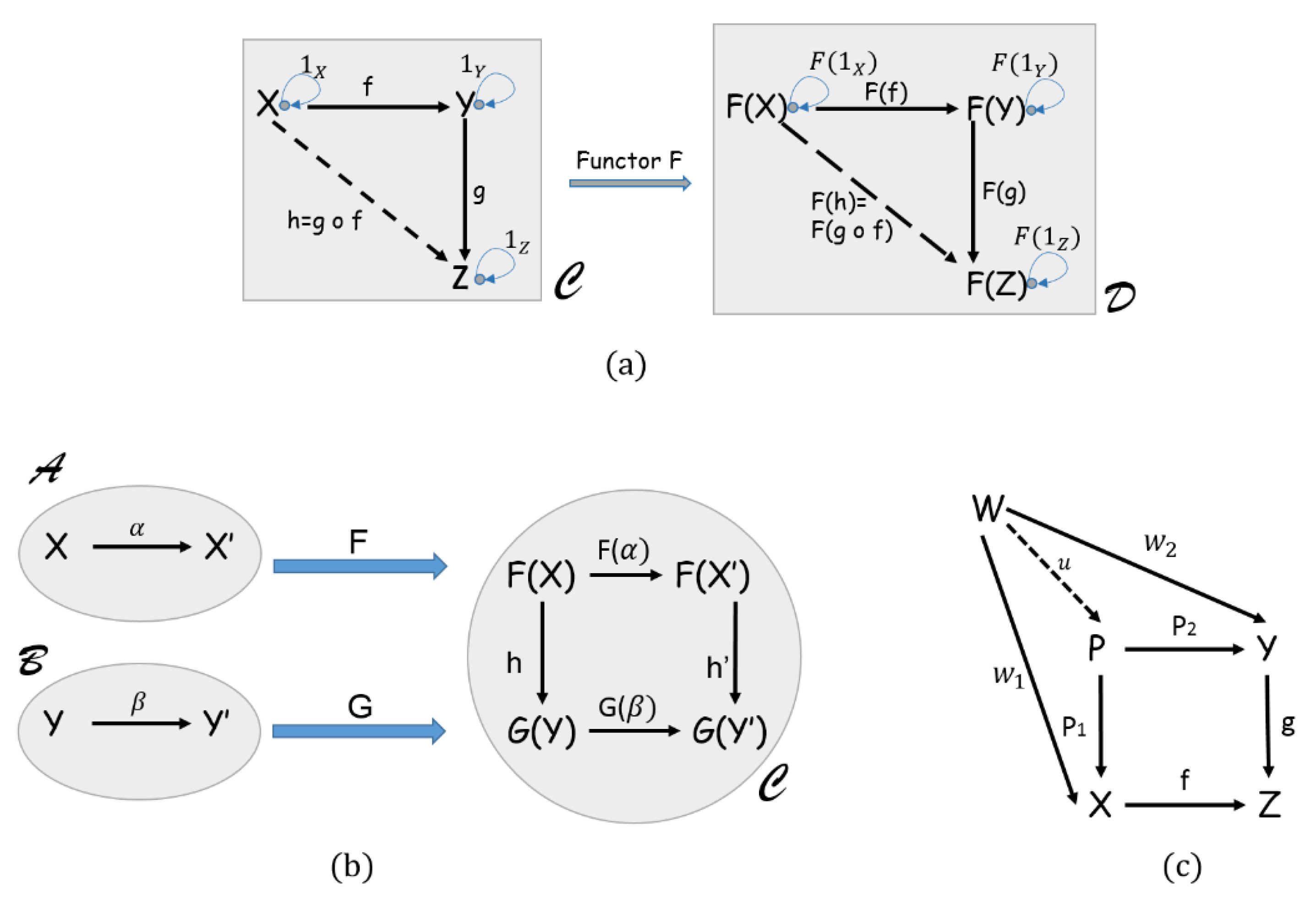
3.3. Category Theory (CT)

In this section, the fundamental concepts of CT as well as related works in the context of collaborative design using this theory are presented.

3.3.1. Category Theory Basic Concepts

The fundamental concepts of CT are presented as follows:
A category consists in a set of objects X, Y, Z, etc. and a set of arrows or morphisms f, g, h, etc. Each morphism f has a domain (dom) and a co-domain (cod) f: X → Y, where X = dom(f) and Y = cod(f) [33]. Given two arrows f: X → Y and g: Y → Z, there is a given morphism g ○ f: X → Z called the composition of g with f (see Figure 1a). Moreover, for each object X, there is a morphism 1X: X → X, called the identity morphism with respect to the property f ○ 1X = f = 1Y ○ f. Whenever the composition is defined, it has to be associative: h ○ (g ○ f) = (h ○ g) ○ f, for all f: X → Y, g: Y → Z and h: X → Z.
A functor F: C ⟹ D between two categories C and D is a mapping of objects to objects and morphisms to morphisms.
An object is called Initial object I if for any object X in a category C there is exactly one morphism from I to X.
An object is called Terminal object T if for any object X in a category C there is exactly one morphism from X to T.
A Comma category is a construction in CT that involves two functors with the same co-domain. This concept allows the source and target object to vary over the image of distinct functors [33]. Let A, B, and C be categories and let F: A ⟹ C and G: B ⟹ C, be functors with the same co-domain. A comma category ca be formed as follows (Figure 1b): the objects are all triples (X, Y, h) where X is an object in A, Y an object in B and h: F(A) → G(B) a morphism in C. The morphisms from (X, Y, h) to (X′, Y′ and h′) are all pairs (α,β), where: X → X′ and β:Y → Y′ are morphisms in A and B respectively, for which the square commutes, that is G(β) ○ h = h′ ○ F(α). The composition of pairs is done componentwise [33].
In a category C a Pullback of arrows f and g with cod(f) = cod(g) consists of the arrows P1 and P2 such that f ○ P1 = g ○ P2. Given any arrow w1: W → X and w2: W → Y with f ○ w1 = g ○ w2, there exists a unique u: w → P with w1 = P1 ○ u and w2 = P2 ○ u (see Figure 1c). The dual of a pullback can be defined as a Pushout structure.

3.3.2. Category Theory in Collaborative Design

In recent years, CT has found wide applications in several domains such as artificial intelligence [34], computer science [35], Systems Engineering (SE) [8] and collaborative design [36]. In the context of collaborative design, Ormandjieva et al. [32] presented an approach using category theory in order to construct a unified multi-agent systems model. Through this model it is possible to represent the communication between the different agents by means of CT. This proposition intends to check the system properties by the construction of categories and functors. Furthermore, another research work based on CT was proposed by Mabrok and Ryan [8]. The researchers applied CT to verify and validate the modelled system design. The authors introduced CT as a formal foundation for model-based systems engineering (MBSE). In this work, the global system is considered as a category and its components as objects. The interrelations between these objects are presented by means of arrows and the different alternatives of the system are introduced as categories. The solution category is related to the system category by functors where each alternative is a result of a particular functor. Additionally, Zhu and Li [37] presented a categorical framework to formally design and implement complex systems as well as to verify the consistency of communication between design and implementation. The presented framework is based on the use of functors in order to verify design categorical models against implementation categorical models. Moreover, Kibret et al. [38] proposed a formalization of the verifiable design process (VDP) through CT. The system models are presented by categories and their constituent parts are defined through objects and morphisms. Categorical structures such as pullback and pushout are used to analyze the different representations of the system and functors are applied to define the abstraction layer of the VDP.
In summary, a multitude of methodologies based on the mathematical formalism of CT can be found in the literature. Although their diversity, a common point between these approaches is presented, that is, the use of CT as a formal tool to support the heterogeneous representations of the system under design. Similar to these approaches cited beforehand, CT will be applied in this research paper as a common formalism to support conflict detection and handling. However, this theory will be used in order to manipulate fine granularity data (i.e., in the form of parameters and constraints) in contrast with previous works where the CT is used to manipulate either system components or system agents without taking into account the parameters and constraints of the system. Categorical structures, such as objects, morphisms, functors, and comma category, will be used in our formalism, as detailed in the next section.

4. Conflict Resolution Approach Based on Category Theory

4.1. Main Concepts

Collaborative design process involves stakeholders from different backgrounds and areas aiming at reaching a common objective about product development [30]. These experts have different views on the system and make use of heterogeneous modeling languages and tools. However, interrelations between these models are inevitable. Consequently, conflicts may appear and have to be carefully considered to guarantee a high quality of the system under design. To tackle this challenge, we propose a new conflict resolution model, based on CT, aiming at diagnosing and handling the inconsistencies between the expert models involved in the collaborative process. On the one hand, our approach is based on rules and patterns, which makes it more flexible. This technique makes removing or adding new rules during the conflict resolution process possible, which in turn can reduce development time in mechatronic design. On the other hand, we use CT in our methodology as a formal framework to illustrate conflict detection and resolution. The motivation of using this theory is its powerful mathematical constructions. Using this theory, graphs will carry all the intuitions coming from the practice and have a formal meaning. Furthermore, the traceability of collaboration between the different stakeholders is ensured in a formal way by means of the different categories containing all the results of this exchange. Moreover, querying graphs in the conflict resolution process is based on category mapping through functors, which makes this action formal and easy at the same time.
The architecture of our approach is illustrated in Figure 2. As a first step, the different parameters of the expert models have to be abstracted into parameters categorical graphs PmCG using CT constructions. This step provides a common formalism that makes the several expert models homogeneous despite their heterogeneity. Then, dependencies among the parameters are established by means of CT through the definition of morphisms representing the dependency coefficient among the different parameters (objects). At this level, the process of diagnosis and handling can start. A set of consistency rules (CRs) is established to identify the constraints to be respected. Then, the conflicts appeared during the collaboration between the EMs are detected through graph patterns matching against the parameters categorical graphs. If the conflicting parameter has some dependencies with another one, the related parameter has to be updated. Consequently, the corresponding parameters categorical graphs have also to be updated and the modified values will be saved in the updated Parameters Categorical Graphs UPmCG. Otherwise, one of the resolution actions (RA) is applied to the conflicting parameter in order to manage this contradiction. The final results of the conflict resolution process will be saved in the final parameters categorical graphs FPmCG to ensure the traceability of collaboration.
Based on this architecture, a Conflict Resolution Problem (CRP) is defined as an 8-tuple: CRP = <EM, PmCG, UPmCG, FPmCG, DCG, CR, GP, RA>, which contains the following elements:
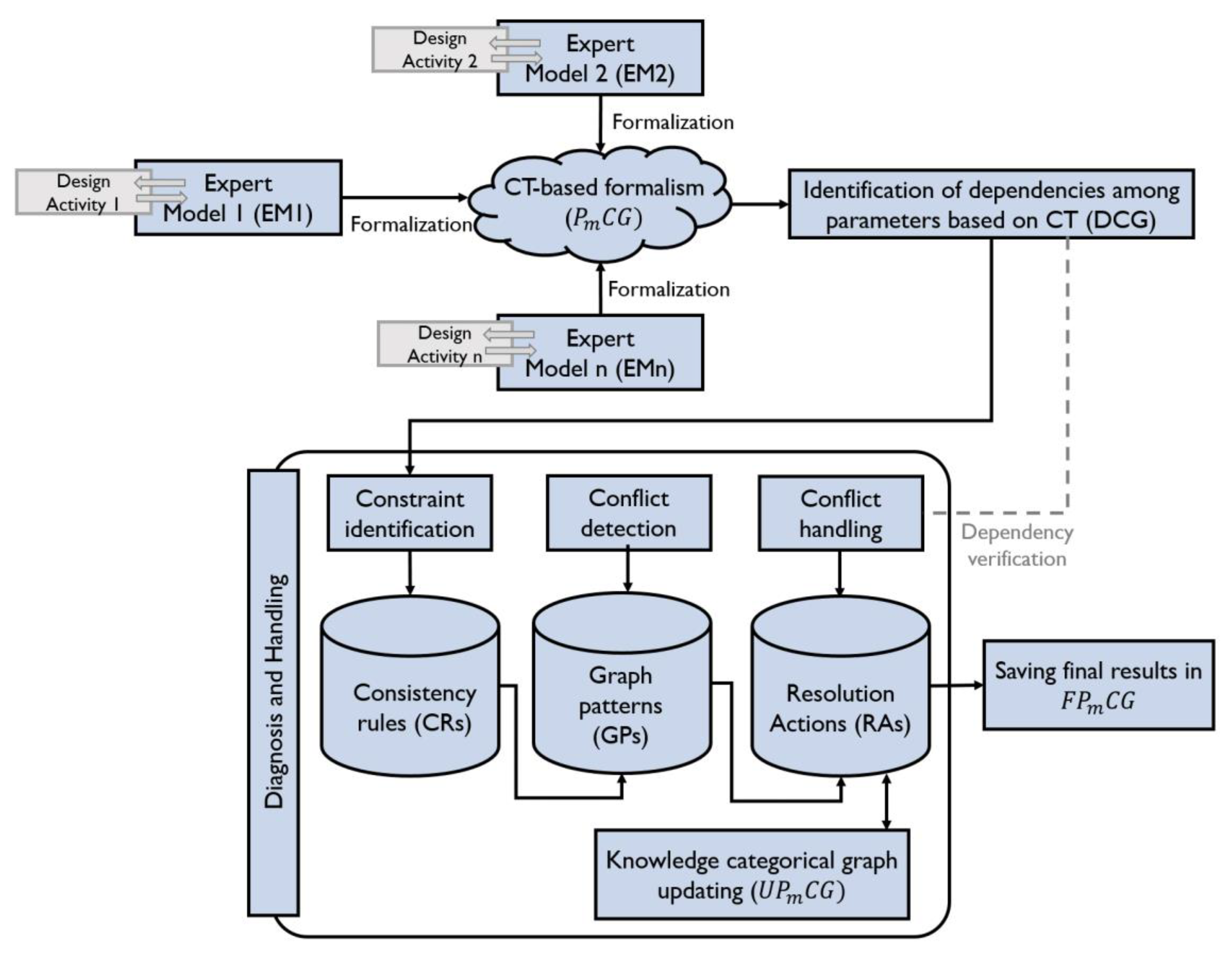
  • Expert Model (EM) refers to a set of models, EM1, EM2, …, EMn, that are relative to different domains and involved in the collaborative process. Examples of expert models may be: a control model using for instance Simulink software [19], a multi-physical model using Modelica language within Dymola software [39], a 3D model with CATIA environment [40] in order to verify the integration of the whole mechanism, a Commercial off-the-shelf (COTS) model to select the appropriate components against the properties obtained from the simulation, etc.
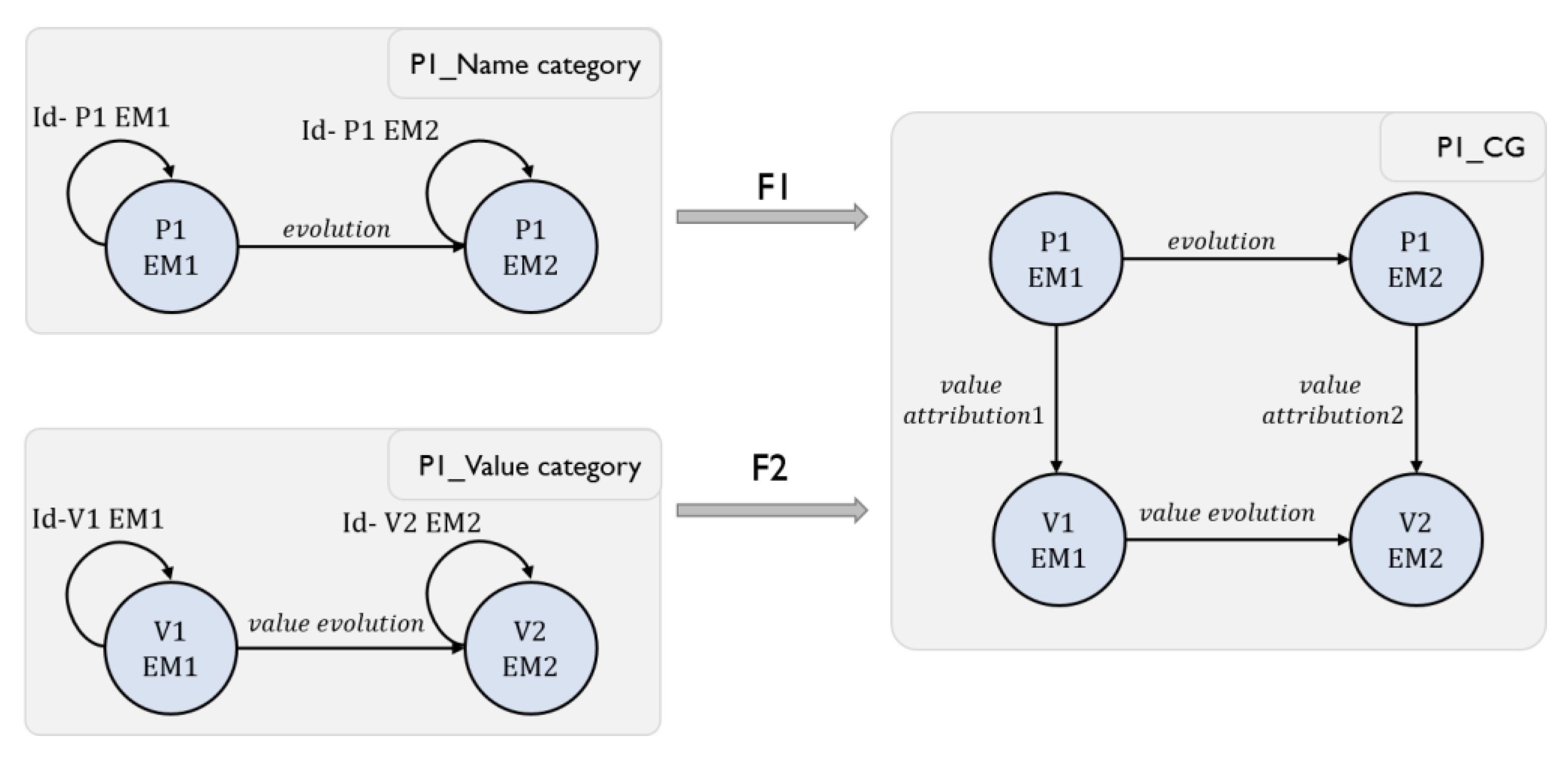
  • Parameters Categorical Graph PCG represents the unified graphs based on category theory, P1CG, P2CG, …, PmCG, which contains crucial parameters extracted from the EMs and will help to capture conflicts between these models. A 5-tuple PmCG = <O, id, Ar, Lo, LAr> is an attributed, directed graph. In the context of CT, this graph represents a category where O = (O1,.., Oj) is a set of objects (i.e., vertices). Each object has its own identity id (i.e., the looped arrow). These objects are the different versions of parameters used by the involved experts as well as their values. Objects are related to each other through a set of arrows or morphisms Ar (i.e., edges). All the objects and arrows have labels (i.e., attributes) Lo and LAr respectively. A sample PmCG, created following the previous definition of comma category, is illustrated in Figure 3. The identity morphisms as well as the composition arrows are not represented in this category in order to avoid cluttering it with a large number of morphisms.
  • Updated Parameters Categorical Graph UPmCG this category will contain the updated values obtained after each iteration of the conflict resolution process. Similar to the PmCG described beforehand, the UPmCG is considered as a category and inherits all the proprieties of the first PmCG. Through these updated categories, traceability can be ensured which will be useful in reuse perspectives.
  • Final Parameter Categorical Graph FPmCG this category will contain the final results obtained after applying the appropriate RAs to the detected conflicts. Similarly, this categorical graph has the same form than the PmCG and UPmCG described previously.
  • Dependency Categorical Graph (DCG) illustrates the existing dependencies between the parameters presented in the PmCG based on category theory. A 5-tuple DCG = <Od, idd, Ard, Lod, LArd> is an attributed, directed graph and represents a category where O = O1, …, Om is a set of objects (i.e., vertices) where m refers to the number of parameters used in the collaborative process. Each object has its own identity idd. The identity morphism represents the internal evolution of each object. It is assumed to be present for the DCG. However, it is seldom shown in order to avoid cluttering the category with an identity morphism for each object. In this graph, the objects are the different parameters used by the involved experts. Objects (i.e., parameters) are related to each other through a set of arrows or morphisms Ard (i.e., edges). These morphisms highlight the dependency between the different parameters. All the objects and arrows have labels (or attributes) Lod and LArd respectively. The morphism labels represent the dependency coefficient of each relation between two objects. These coefficients will be used in conflict resolution process. A sample DCG is illustrated in Figure 4.
  • Consistency rule (CR): A set of consistency rules, CR1, CR2, …, CRp, between elements of EMs. The EMs will be considered inconsistent if CRs are not respected.
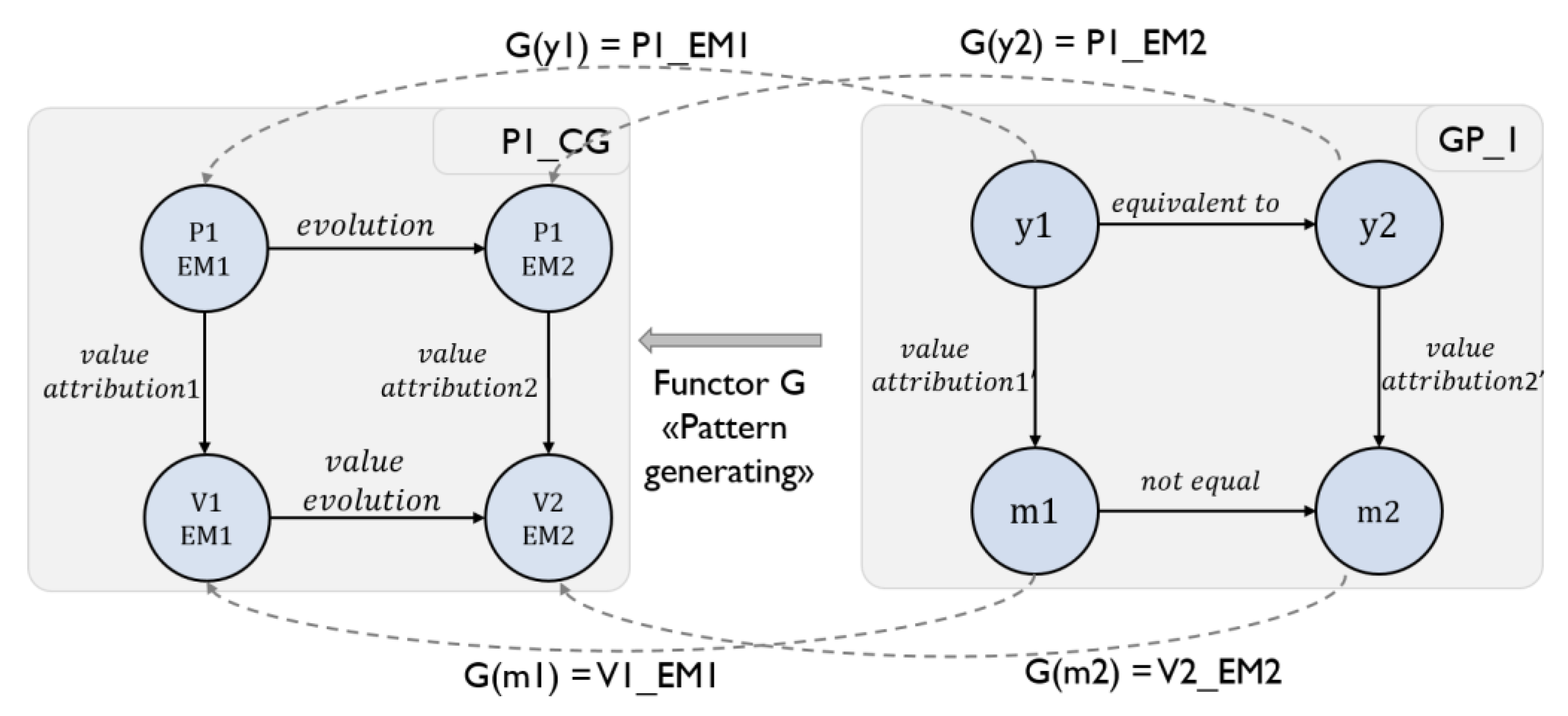
  • Graph Pattern (GP), GP1, GP2, …, GPq, a set of categories aiming at describing the existence of a conflict. Querying the different PmCGs using these patterns can help in conflict detection. This graph is defined as a category containing a set of objects and morphisms. The objects of this category are either a string representing the parameter names and is unmodified through the different iterations or a variable for parameter values definition. The morphisms in the GP illustrate the value attribution for each parameter. The form of the GP can vary dependently to the PmCG to be queried. An example of GP is illustrated in Figure 5. The GP1 describes the existence of a conflict between two expert models where the value m1 is not equal or less than m2. The second GP2 represents a conflict among three expert models where m1 is not equal or less than m2 and m3. Moreover, a conflict can be detected when the values of m2 and m3 are not equal.
  • Resolution action (RA): A set of actions, RA1, RA2, …, RAr, to resolve the conflicts detected by means of GPs. These actions cover modifying the value of the conflicting parameter, tolerating the conflict and ignoring it. The choice of these actions is ensured by the project manager and depends on the current context as well as the detected conflicts.

4.2. Proposed Methodology

As aforementioned, CT is used in this paper to provide a formal framework in order to diagnose and handle the conflicts during mechatronic collaborative design process. The mathematical formalism of CT provides a formal conflict detection and resolution through using the functor concept. All categories defined in this formalism satisfy the formal definitions of CT mentioned beforehand. Moreover, using this mathematical theory collaboration traceability is ensured for reuse perspectives. Our methodology is composed of seven main steps. The flowchart of the proposed approach is presented in Figure 6.

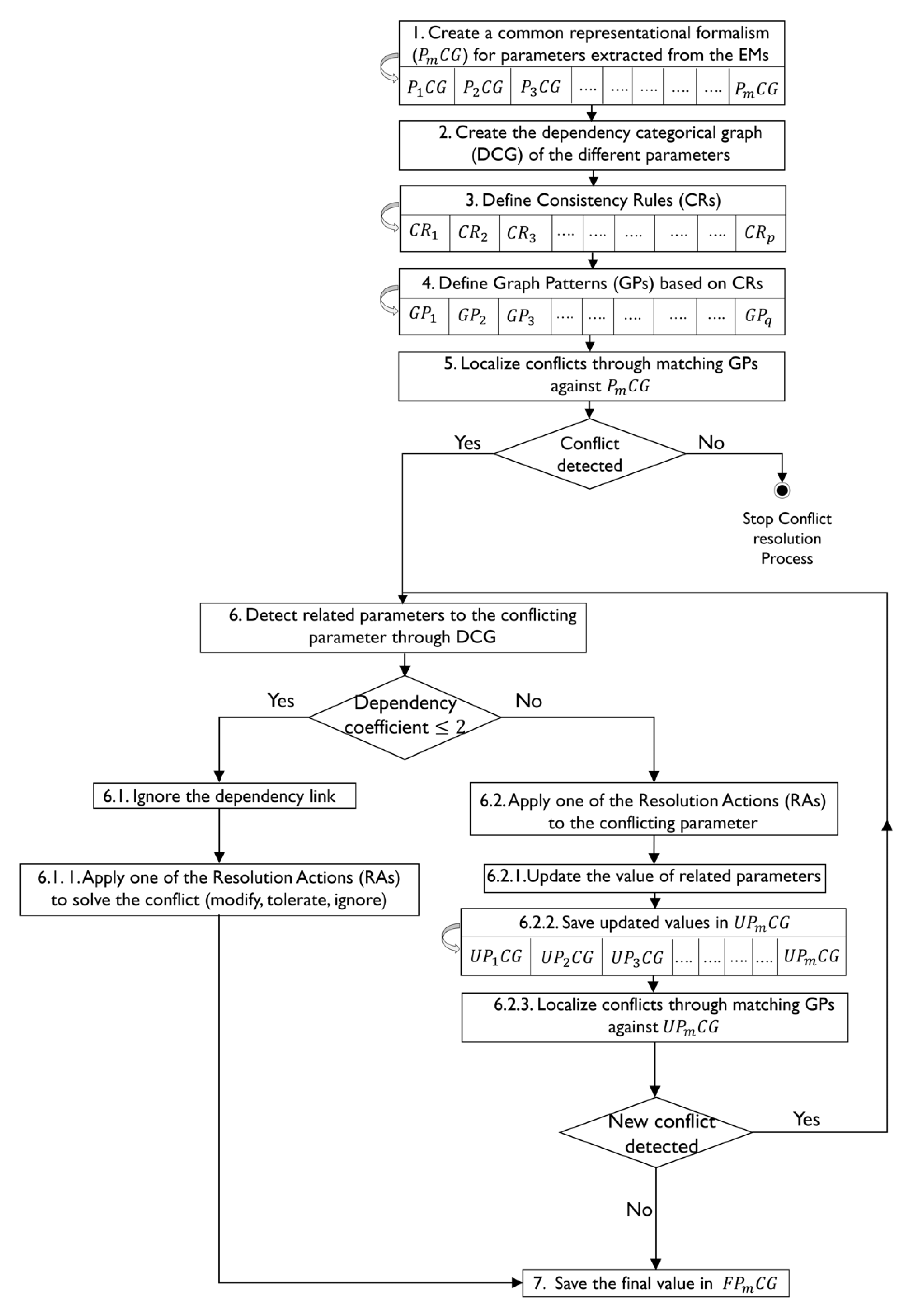
4.2.1. Step 1: Creating a Common Representational Formalism (PmCG) Based on CT for Parameters Extracted from Expert Models (EMs)

According to the model-driven architecture (MDA) introduced by the object management group (OMG) [41], a model can be defined as a reality representation and an abstraction of meaningful and relevant things to the stakeholders, described using well-defined languages [6]. Each model contains a variety of knowledge relative to specific expert models. The knowledge defines how different elements are related to each other. Thus, a model can be considered as a set of elements and relations.
For this reason, it is natural to consider models as graphs. Hence, instead of working directly on the heterogeneous model languages, a unifying formalism is required. These graphs have a formal meaning in the context of CT and highlight all the intuitions coming from the practice. As a first step of our methodology, a formal as well as comprehensive framework is established by means of this mathematical theory. Herzig [7] argued that translating all parameters contained in models is not meaningful. Hence, only crucial parameters will be considered in the conflict resolution problem. These parameters are called crucial since their contribution in reaching the project objectives is considered important [42]. To extract knowledge, a close exchange between the project manager and all the engineers involved in the design process is recommended. Some approaches to extract crucial knowledge also exist using multi-criteria decision-making methods [43].
Thus, for each crucial parameter, a parameter categorical graph (PmCG) is created. The idea is to consider parameters as categories, the objects as the different versions of the parameter used by the EMs and the morphisms as the progress of the concerned parameter from an expert model to another one. Each object in the category has an identity morphism illustrating the natural representation of internal evolution of parameter value. At the end of this step, a set of categories PmCG are obtained where m represents the number of the crucial parameters involved in the collaborative design.

4.2.2. Step 2: Creating the Parameters Dependency Categorical Graphs (DCG)

During the collaborative mechatronic design, interrelations between the EMs as well as their elements are likely to occur. These interrelations may cause several conflicts in the design process. In order to facilitate conflict detection and handling, these dependencies have to be represented in a formal way. Hence, at this level, the project manager creates a dependency graph based on CT in order to illustrate the relations between the objects. The objects of this category refer to the involved parameters in the collaborative design, whereas the morphisms represent the dependency between these parameters. The labels of morphisms highlight the value of dependency coefficient between the corresponding parameters. The values of this coefficient range from 1 to 3 as shown in Table 1.
The value “1” refers to a low dependency between the objects, “2” indicates that the two objects are moderately dependent and “3” denotes a high dependency. The dependency coefficients are evaluated based on the knowledge and previous experiences of the project manager. For each mechatronic system design, a unique DCG is created which will be used in the following steps of the conflict resolution process.

4.2.3. Step 3: Defining Consistency Rules (CRs)

As introduced beforehand, an inconsistency is defined as a state of conflict, marked by the presence of a contradiction. This term is used to denote a situation in which a set of descriptions do not respect some relationships that should hold among them. These relationships can be expressed as a consistency rule (CR) against which descriptions can be checked [1]. CRs refer to constraints which need to be respected by the involved models. In our approach, CRs are composed of conditions describing relationships between the EM parameters. For example, one CR can be written in the following form: CR1 = “P1EM2 must be equal or less than P1EM1”.

4.2.4. Step 4: Defining Graph Patterns (GPs)

As argued by Herzig et al. [25] it is impossible to capture all inconsistencies due to the lack of perfect knowledge about the processes. Consequently, only known inconsistencies can be defined. These known inconsistencies can be considered as patterns. Hence, graph patterns aim at describing the existence of a conflict in a PmCG. Therein, GPs are illustrated graphically using CT concepts (as shown in Figure 5).

4.2.5. Step 5: Locating Conflicts through Matching GPs against PmCGs

At this level, the conflicts presented during the design process can be localized through querying the PmCG using graph patterns. In the context of CT, this matching between the GPs and PmCG is established in a formal way through functors. As defined previously, functors are considered as a mapping between the different objects as well as morphisms from one category to another one. An example of this mapping is illustrated through Figure 7. The image of y1, y2, m1 and m2 of GP category through the functor “G” are respectively P1EM1, P1EM2, V1EM1 and V2EM2 in P1CG category. This mapping allows the verification of the consistency between the different values of the same parameter in the corresponding PmCG. All we need is to generate a functor from GP to the desired PCG to check consistency. Consequently, if these values are not equal, then, a conflict is detected and has to be carefully handled following the next steps. Otherwise, if all the values are consistent, the conflict resolution process can be stopped.

4.2.6. Step 6: Detecting Related Parameters to the Conflicting Parameter through Checking DCG

At this level, the detected conflict must be resolved. If the dependency coefficient (c12, c14, c32, etc. in Figure 4) between two objects (i.e., parameters P1, P2, etc.) is equal or less than to 2, the dependency link is ignored, and a resolution action (RA) has to be applied to solve this conflict. The RAs in our approach can be either a modifying, tolerating or ignoring actions. Ignoring action means that the detected conflict is no longer of interest, whereas tolerating conflicts refers to parameter tolerance where the decision maker (i.e., the project manager) decides to tolerate a parameter by considering a slight deviation from desired values. However, modifying action requires a modification in the value of the concerned parameter. In this case, the engineer needs to update its expert model until finding the appropriate value. Hence, depending on the current context and the detected conflicts, the decision maker can decide how to react to handle these conflicts. Thus, resolution action (RA) is based on a set of handling rules, which are defined as: a tolerating handling rule, a modifying handling rule or an ignoring handling rule.
Nonetheless, if the dependency coefficient between two parameters is more than 2, this link has to be taken into consideration and the RA must be chosen regarding the related parameters to the conflicting one in order to prevent new conflicts to appear (Step 6.2 in Figure 6). At this level, the values of related parameters have to be updated and saved in the UPmCG (Step 6.2.1 and 6.2.2). Then, a new mapping between GPs and PmCG is established in order to check the existence of new conflicts. If new conflicts are presented, Step 6 will be repeated until reaching the appropriate trade-off between all the parameters. Otherwise, the final results will be saved, and the conflict resolution process can be stopped.

4.2.7. Step 7: Saving the Final Values of Each Parameter in the Final Parameter Categorical Graph FPmCG

The last step in the CRP consists in saving the final results obtained after the resolution of all conflicts in the final parameters category FPmCG. This category will be used for traceability perspectives during the collaborative process.
Our proposed methodology based on rules, patterns and mathematical constructions of CT provides a formal framework to detect as well as handle conflicts between the different stakeholders during mechatronic collaborative design. This framework is considered as a flexible solution since rules can be added, modified or even deleted without influencing all the conflict resolution process. Moreover, conflict detection and resolution in our methodology is based on different mathematical constructions of CT, which keeps all the insights of the practice in a formal and easy way and facilitates traceability of collaboration. In order to illustrate the capacity of the proposed approach, a mechatronic system design will be studied in the next section.

5. Case Study

In order to demonstrate our approach, an Elector-Mechanical Actuator (EMA) of an aileron for a small aircraft is considered in this paper. The EMA is a mechatronic system used to actuate the aileron of the aircraft and replace the usual rod, lever and cables mechanisms [44,45].
Several EMA architectures can be studied such as a direct drive, 3-bars or 4-bars architecture. In this work, our chosen structure is the 3-bars architecture as shown in Figure 8, adopted from [45]. The EMA is linked to the aileron and the wing through two spherical joints. It contains a DC motor controlled by a control unit, a gearbox and a ball screw-nut assembly aiming at transforming the motor rotation movement into the translation of the rod to push and pull the aileron. The EMA is considered as a multi-physical system since it encompasses mechanics, control, electrics, etc. Its multi-disciplinary aspect makes the EMA an interesting example to validate our approach. The different steps of our methodology described previously (see Figure 6) will be applied to the EMA system.

5.1. Step 1: Creating a Common Representational Formalism (PmCG) Based on CT for Parameters Extracted from Expert Models (EMs)

The first step in our proposed approach consists in creating a common formalism for parameters of each expert model using CT concepts. Four expert models (EMs) are involved in the EMA system design. EMR refers to a specification model where the requirements to be respected are identified. These requirements are defined through the SysML requirement diagram in Magic Draw environment as illustrated in Figure 9. The response time of the EMA must not exceed 600 ms and the static error shall be less than 2 deg. The EMA mass is 3 Kg. The required power shall not exceed 250 W and the system cost must not exceed 2000 €. All the EMA components shall fit into the allocated area between the aileron and the wing.
EMMP represents a multi-physical model using Modelica language. This model is based on differential, discrete and algebraic equations in order to describe the dynamic response of the EMA [46]. The EMA multi-physical model within Dymola environment is shown in Figure 10. This model is created using components from Modelica library. It contains a DC motor powered by a PID controller and connected to a gearbox. The produced rotational movement is converted into a translation by means of the screw-nut.
Based on the multi-physical model another expert model is established (EMC). The existing commercial, off-the-shelf (COTS) components are chosen conforming within the simulation results. This model contains the characteristics of the chosen components (see Figure 11a). The final expert model is a 3D model (EM3D) using CATIA environment. This model is created in order to verify the integration of the whole mechanism in the aileron and the wing assembly (see Figure 11b). In our case study, a well-defined workflow while creating each expert model must be considered. This workflow starts with the requirement model (EMR). Then, the multi-physical model (EMMP) is provided. Once the simulation results are obtained from the multi-physical model (EMMP), the existing COTS components (EMC) will be found. The last model (EM3D) is used to verify the 3D integration of EMA mechanism in the assembly of the aileron and the wing.
Once the expert models are created, the evolution of parameters used in the EMA design by different EMs will be illustrated through the PmCG. These categories contain only crucial parameters extracted from the EMs. To do so, we recommend an effective exchange between the stakeholders to extract the most important parameters. The crucial parameters of EMA system are listed in Table 2. For each parameter, a PmCG is created based on CT concepts. An excerpt of a PCG of the parameter P4 (maximal power for EMA system) is illustrated in Figure 12.
All what we need to ensure that the created category respects the mathematical definitions in the context of CT is to prove the existence of composition, identity as well as associativity. Let PwEMR, PwEMMP and PwEMC be three different versions of the maximal power such as EMR interacts with EMMP, which in turn interacts with EMC then, EMR can interact with EMC indirectly through EMMP, which highlights the existence of a composition of morphisms between EMR and EMC. Moreover, the different values of Pw are represented as objects in this category. The first value in the requirement model evolves into a new value in EMMP, which in turn evolves to another value in EMC. This means that the value in EMR can evolve indirectly to the value in EMC. Let multi-physical activity, cots activity and verification activity be the morphisms such as multi-physical activity: PwEMR → PwEMMP, cots activity: PwEMMP → PwEMC and verification activity: PwEMR → PwEMC. It is clear that multi physical activity ○ (cots activity ○verification activity) = (multi physical activity ○ cots activity) ○ verification activity, which verifies the associativity property. The identity arrows for each object in this category exist to represent the internal evolution of the Pw parameter and its values. Each object must have an identity morphism. However, it is seldom shown in order to avoid cluttering the category with an identity morphism for each object.

5.2. Step 2: Creating the Parameters Dependency Categorical Graphs (DCG)

In this step, the DCG of crucial parameters is established (see Figure 13). The project manager attributes the dependency coefficients, indicating the degree of dependency, through morphisms between the parameters according to the scale proposed in Table 1. These coefficients are defined based on the project manager expertise. The resolution actions will be chosen based on the dependency coefficients between the parameters, as will be explained in the following steps.

5.3. Step 3: Defining Consistency Rules (CRs)

Here, the different CRs are defined in order to describe the relationships that must hold between the different parameters of EMs. An excerpt of some CRs for EMA system design is presented in Scheme 1.

5.4. Step 4: Defining Graph Patterns (GPs)

Based on the aforementioned defined CRs, graph patterns are created in order to formulate the expected relationships among the four EMs of EMA system that will cause the conflict occurrence as described in Figure 5. Each morphism between two different values of the same parameter in the graph pattern highlights the non-respect of a CR.

5.5. Step 5: Locating Conflicts through Matching GPs against PmCG

At this level, the conflicts are detected by means of matching the GP against the PmCG of each crucial parameter in EMA design. This step is achieved through using the functor concept as described in Section 4.2.5. An example of this mapping is illustrated through Figure 14. All the remaining PmCGs have to be mapped in the same way in order to locate the detected conflicts during EMA system design. The highlighted rows in Table 2 represent the conflicting parameters detected during the first iteration of our conflict resolution process.

5.6. Step 6: Detecting Related Parameters to the Conflicting Parameter through Checking DCG

Once the conflicts are located in the first iteration, the related parameters have to be detected. If the dependency coefficient is ≤ 2, the link will be ignored. This decision is made by the project manager in order to simplify the conflict resolution process. Otherwise, the high dependency between parameters will be taken into consideration during the conflict resolution. In our case, the parameters dependency flows of the first iteration are established referring to the DCG as shown in Table 3. At this level, the value of the static error Se will be modified, then, the value of the related parameters (Rt, Pw, Mass and Rm) will be updated and saved in the corresponding UPCG. After this modification, the conflict in static error (Se) value is resolved. Consequently, we move to the second iteration where the conflict in the Mass value will be handled. We suggest in this case the tolerance of this conflict by considering a slight modification in the required value defined in EMR. The remaining conflicts after this iteration are shown in the second column of Table 3. This step will be repeated until handling all the conflicts.

5.7. Step 7: Saving the Final Values of Each Parameter in the Final Parameter Categorical Graph (FPCG)

Once all the conflicts are handled successfully, the final results are saved in the FPmCG. Table 4 illustrates the final results obtained after the conflict resolution process.
During conflict resolution of the static error (Se) parameter, a modification in the value of the response time (Rt) has occurred due to their dependency. This modification ameliorates the response time of the system, as shown in Figure 15.
The final PCG of Rt after the conflict resolution process is represented in Figure 16a. Moreover, the project manager decides to tolerate the non-respect of the requirement in the global mass parameter. Hence, the value of the Mass in the requirement model (EMR) is modified. This value will be saved in the final PCG of Mass parameter as illustrated in Figure 16b. Furthermore, in EM3D the engineer adjusts the values of his 3D design according to the final COTS components chosen in the EMC (see Table 4).

6. Discussion

In this section, the main contributions of our proposed approach are highlighted. As aforementioned, our main goal is to detect and manage conflicts between fine granularity data during collaborative design in a formal way. The existing approaches in this context do not present explicit solutions to handle conflicts between parameters and constraint, manual processes are suggested to solve detected conflicts. Furthermore, rule and pattern-based approaches are presented in the literature as an efficient solution to manage inconsistencies among heterogeneous models. Despite their flexibility, traceability of collaboration as well as dependencies between model elements are overlooked in these methodologies. Hence, we proposed a new conflict resolution process combining pattern and rule-based methodologies with constraints and parameters approaches using the concepts of category theory. The methodology presented in this paper allows conflict detection in a formal way using category mapping through functors.
Additionally, the different versions of the Parameters categorical graphs (PmCG, UPmCG and FPmCG) ensure the traceability of the collaboration evolution for reuse perspectives. With this formal representation, we can identify that the value of a given parameter is modified by a given expert model at a given time. Moreover, our proposition takes into account the change propagation caused by dependencies between the different parameters, which is overlooked in the existing approaches. Nevertheless, the proposed methodology presents some limits. On one hand, as mentioned beforehand, identifying crucial knowledge in our approach is based on meetings between the different stakeholders involved in the design process. This method is time-consuming and difficult to organize for mechatronic systems design. Hence, formal methods based on mathematical concepts are needed in order to extract the most important knowledge for the collaboration in a formal and easy way. On the other hand, dependency coefficients in the DCG are identified by the project manager based on his knowledge and previous experiences. This assumption makes the conflict resolution process centralized on the project manager decisions. Thus, automated solutions might be integrated into our proposed process.

7. Conclusions

The proposed approach in this research paper enabled conflict detection and management during mechatronic systems design. This approach was established by means of rule and pattern-based approach as well as parameter and constraint approach combination while using the powerful concepts of category theory. This theory provided, on the one hand, a unified and formal representation of the knowledge involved in the collaborative design and, on the other hand, a formal conflict detection method based on categories mapping by means of functors. The common representational formalism based on CT concepts allowed collaboration traceability, which will be efficient for reuse perspectives. Our methodology was applied to a collaborative scenario of the electro-mechanical actuator of the aileron (EMA) regarding different expert models having common parameters presenting conflicting values. This proposition had proven its efficiency in conflict detection and handling of the EMA system design and can be further adapted for other case studies.
In future works, we will explore how category theory can be used in the crucial knowledge identification process, which will reduce the execution time of this task. Thereafter, we will investigate how automated methods may be integrated into our proposed approach to facilitate dependency coefficient identification.

Author Contributions

Conceived the idea, M.F., F.M., R.G., A.M. and J.-Y.C.; implementation, M.F.; writing—original draft preparation, M.F.; writing—review and editing, F.M.; supervision, F.M., R.G., A.M. and J.-Y.C. All authors have read and agreed to publish this version of the manuscript.

Funding

This research received no external funding.

Institutional Review Board Statement

Not applicable.

Informed Consent Statement

Not applicable.

Data Availability Statement

Not applicable.

Conflicts of Interest

The authors declare no conflict of interest.

References

  1. Feldmann, S.; Kernschmidt, K.; Wimmer, M.; Vogel-Heuser, B. Managing inter-model inconsistencies in model-based systemsengineering: Application in automated production systems engineering. J. Syst. Softw. 2019, 153, 105–134. [Google Scholar] [CrossRef]
  2. Basirati, M.R.; Zou, M.; Bauer, H.; Kattner, N.; Reinhart, G.; Lindemann, U.; Vogel-Heuser, B. Towards systematic inconsistencyidentification for product service systems. In Proceedings of the DESIGN 2018 15th International Design Conference, DS 92, Dubrovnik, Croatia, 21–24 May 2018; pp. 2811–2820. [Google Scholar]
  3. Fradi, M.; Gaha, R.; Mlika, A.; Mhenni, F.; Choley, J.Y. Design of an Electronic Throttle Body Based on a New Knowledge Sharing Engineering Methodology. In Proceedings of the International Conference Design and Modeling of Mechanical Systems, Hammamet, Tunisia, 18–20 March 2019; pp. 55–63. [Google Scholar]
  4. Dávid, I.; Denil, J.; Gadeyne, K.; Vangheluwe, H. Engineering Process Transformation to Manage (In) consistency. In Proceedings of the 1st International Workshop on Collaborative Modelling in MDE (COMMitMDE 2016) Co-Located With ACM/IEEE 19th International Conference on Model Driven Engineering Languages and Systems (MoDELS 2016), St. Malo, France, 4 October 2016; pp. 7–16. [Google Scholar]
  5. Zhu, M.; Kuang, H.; Li, J. Representation of Categorical Specification of Self-Configurations in Reactive Autonomic Systems Framework. J. Comput. Commun. 2018, 6, 34–48. [Google Scholar] [CrossRef] [Green Version]
  6. Fisher, A.; Nolan, M.; Friedenthal, S.; Loeffler, M.; Sampson, M.; Bajaj, M.; Hart, L. 3.1. 1 model lifecycle management for MBSE. In Proceedings of the INCOSE International Symposium, Las Vegas, NV, USA, 30 June–3 July 2014; Volume 24, pp. 207–229. [Google Scholar]
  7. Herzig, S.J. A Bayesian Learning Approach to Inconsistency Identification in Model-Based Systems Engineering. Ph.D. Thesis, Georgia Institute of Technology, Atlanta, GA, USA, 2015. [Google Scholar]
  8. Mabrok, M.A.; Ryan, M.J. Category theory as a formal mathematical foundation for model-based systems engineering. Appl. Math. Inf. Sci. 2017, 11, 43–51. [Google Scholar]
  9. Spivak, D.I. Category theory for scientists (Old version). arXiv 2013, arXiv:1302.6946. [Google Scholar]
  10. Finkelstein, A.C.; Gabbay, D.; Hunter, A.; Kramer, J.; Nuseibeh, B. Inconsistency handling in multi-perspective specifications. IEEE Trans. Softw. Eng. 1994, 20, 569–578. [Google Scholar] [CrossRef] [Green Version]
  11. Medvidovic, N.; Taylor, R.N. Software architecture: Foundations, theory, and practice. In Proceedings of the 2010 ACM/IEEE 32nd International Conference on Software Engineering, Cape Town, South Africa, 2–8 May 2010; Volume 2, pp. 471–472. [Google Scholar]
  12. Torres, W.; Van den Brand, M.G.; Serebrenik, A. A systematic literature review of cross-domain model consistency checking bymodel management tools. Softw. Syst. Model. 2020. [Google Scholar] [CrossRef]
  13. Axelsson, J. Achieving System-of-Systems Interoperability Levels Using Linked Data and Ontologies. In Proceedings of the INCOSE International Symposium, Cape Town, South Africa, 18–23 July 2020; Volume 30, pp. 651–665. [Google Scholar]
  14. Guychard, C.; Guerin, S.; Koudri, A.; Beugnard, A.; Dagnat, F. Conceptual interoperability through models federation. In Proceedings of the Semantic Information Federation Community Workshop, Miami Beach, FL, USA, 29 September–4 October 2013; p. 23. [Google Scholar]
  15. Berriche, A.; Mhenni, F.; Mlika, A.; Choley, J.Y. Towards model synchronization for consistency management of mechatronicsystems. Appl. Sci. 2020, 10, 3577. [Google Scholar] [CrossRef]
  16. Qamar, A.; Meinhart, M.; Walley, G. Model based systems engineering to support failure mode avoidance for driver-assistancesystems. In Proceedings of the 2017 IEEE Aerospace Conference, Big Sky, MT, USA, 4–11 March 2017; pp. 1–9. [Google Scholar]
  17. PLM Automation, Teamcenter. Available online: https://www.plm.automation.siemens.co-m/global/fr/products/teamcenter (accessed on 15 January 2021).
  18. Dassault Systèmes, MagicDraw. Available online: https://www.nomagic.com/products/ma-gicdraw (accessed on 23 October 2020).
  19. Mathworks, Simulink. Available online: https://www.mathworks.com/products/simulink (accessed on 15 January 2021).
  20. Bock, C.; Zha, X.; Suh, H.W.; Lee, J.H. Ontological product modeling for collaborative design. Adv. Eng. Inform. 2010, 24, 510–524. [Google Scholar]
  21. Penas, O.; Plateaux, R.; Patalano, S.; Hammadi, M. Multi-scale approach from mechatronic to Cyber-Physical Systems for thedesign of manufacturing systems. Comput. Ind. 2017, 86, 52–69. [Google Scholar]
  22. Qamar, A.; Paredis, C.J.; Wikander, J.; During, C. Dependency modeling and model management in mechatronic design. J. Comput. Inf. Sci. Eng. 2012, 12, 041009. [Google Scholar] [CrossRef] [Green Version]
  23. Törngren, M.; Qamar, A.; Biehl, M.; Loiret, F.; El-Khoury, J. Integrating viewpoints in the development of mechatronic products. Mechatronics 2014, 24, 745–762. [Google Scholar] [CrossRef]
  24. Legendre, A.; Lanusse, A.; Rauzy, A. Toward model synchronization between safety analysis and system architecture design inindustrial contexts. In Proceedings of the International Symposium on Model-Based Safety and Assessment, Trento, Italy, 14–16 September 2017; pp. 35–49. [Google Scholar]
  25. Herzig, S.J.; Qamar, A.; Paredis, C.J. An approach to identifying inconsistencies in model-based systems engineering. Procedia Comput. Sci. 2014, 28, 354–362. [Google Scholar] [CrossRef] [Green Version]
  26. Herzig, S.J.; Paredis, C.J. A conceptual basis for inconsistency management in model-based systems engineering. Procedia Cirp 2014, 21, 52–57. [Google Scholar] [CrossRef] [Green Version]
  27. Kleiner, S.; Anderl, R.; Gräb, R. A collaborative design system for product data integration. J. Eng. Des. 2003, 14, 421–428. [Google Scholar] [CrossRef]
  28. Badin, J.; Chamoret, D.; Gomes, S.; Monticolo, D. Knowledge configuration management for product design and numericalsimulation. In Proceedings of the 18th International Conference on Engineering Design (ICED 11), Lyngby/Copenhagen, Denmark, 15–18 August 2011; Volume 6, pp. 161–172. [Google Scholar]
  29. Mcharek, M.; Azib, T.; Hammadi, M.; Choley, J.Y.; Larouci, C. Knowledge sharing for mechatronic systems design andoptimization. IFAC Pap. 2018, 51, 1365–1370. [Google Scholar] [CrossRef]
  30. Mcharek, M.; Hammadi, M.; Azib, T.; Larouci, C.; Choley, J.Y. Collaborative design process and product knowledge methodologyfor mechatronic systems. Comput. Ind. 2019, 105, 213–228. [Google Scholar] [CrossRef]
  31. Kuang, H. Towards a Formal Reactive Autonomic Systems Framework Using Category Theory. Ph.D. Thesis, Concordia University, Montreal, QC, Canada, 2013. [Google Scholar]
  32. Ormandjieva, O.; Bentahar, J.; Huang, J.; Kuang, H. Modelling multi-agent systems with category theory. Procedia Comput. Sci. 2015, 52, 538–545. [Google Scholar] [CrossRef] [Green Version]
  33. Roman, S. An Introduction to the Language of Category Theory; Birkhäuser: Cham, Switzerland, 2017. [Google Scholar]
  34. Phillips, S. A general (category theory) principle for general intelligence: Duality (adjointness). In Proceedings of the International Conference on Artificial General Intelligence, Melbourne, Australia, 15–18 August 2017; pp. 57–66. [Google Scholar]
  35. Guo, J. Using category theory to model software component dependencies. In Proceedings of the Ninth Annual IEEE International Conference and Workshop on the Engineering of Computer-Based Systems, Lund, Sweden, 8–11 April 2002; pp. 185–192. [Google Scholar]
  36. Suto, H.; Patitad, P. A representation model of collaboration in design process. In Proceedings of the 2015 10th Asian Control Conference (ASCC), Kota Kinabalu, Malaysia, 31 May–3 June 2015; pp. 1–5. [Google Scholar]
  37. Zhu, M.; Li, J. Towards a Categorical Framework for Verifying Design and Implementation of Concurrent Systems. J. Comput. Commun. 2018, 6, 227–246. [Google Scholar] [CrossRef] [Green Version]
  38. Kibret, N.; Edmonson, W.; Gebreyohannes, S. Category theoretic based formalization of the verifiable design process. In Proceedings of the 2019 IEEE International Systems Conference (SysCon), Orlando, FL, USA, 8–11 April 2019; pp. 1–8. [Google Scholar]
  39. Dassault Systèmes. Available online: https://www.3ds.com/fr/produits-et-services/catia/produits/dymola/ (accessed on 10 July 2020).
  40. Dassault Systèmes. Available online: https://www.3ds.com/fr/produits-et-services/catia/ (accessed on 10 July 2020).
  41. Object Management Group. Model Driven Architecture (MDA)—MDA Guide 2.0. 2014. Available online: https://www.omg.org/mda/presentations.htm (accessed on 14 May 2021).
  42. Brigui-Chtioui, I.; Saad, I. A multiagent approach for collective decision making in knowledge management. Group Decis. Negot. 2011, 20, 19–37. [Google Scholar] [CrossRef]
  43. Saad, I.; Chakhar, S. A decision support for identifying crucial knowledge requiring capitalizing operation. Eur. J. Oper. Res. 2009, 195, 889–904. [Google Scholar] [CrossRef]
  44. Mhenni, F.; Choley, J.Y.; Caron, F.; Munck, A. Collaborative Mechatronic Design and Systems Engineering: An Educational Experiment with KARREN. In Proceedings of the 2018 IEEE International Systems Engineering Symposium (ISSE), Rome, Italy, 1–3 October 2018; pp. 1–7. [Google Scholar]
  45. Siala, H.; Mhenni, F.; Choley, J.Y.; Barkallah, M.; Louati, J.; Haddar, M. Toward a Robust Design of an Aileron Electromechanical Actuator: Sensitivity Analysis and Parametric Tolerancing Using a Variational Approach. IEEE Syst. J. 2020, 14, 3977–3986. [Google Scholar] [CrossRef]
  46. Shitahun, A.; Ruge, V.; Gebremedhin, M.; Bachmann, B.; Eriksson, L.; Andersson, J.; Fritzson, P. Model-based dynamicoptimization with openmodelica and casadi. IFAC Proc. Vol. 2013, 46, 446–451. [Google Scholar] [CrossRef]
Figure 1. Fundamental concepts of Category theory: (a) A mapping from category C to D through a functor “F”, (b) Comma category and (c) a pullback structure, adopted from [33].
Applsci 11 04486 g001
Figure 2. Architectural overview of the conflict resolution model.
Applsci 11 04486 g002
Figure 3. Parameter Categorical Graph (P1CG) created through two functors (F1 and F2). P1EM1, P1EM2, V1EM1, V2EM2 are the objects of PmCG. Evolution, value attribution, etc. are the morphisms. The identity and composition morphisms are not represented.
Applsci 11 04486 g003
Figure 4. Dependency Categorical Graph (DCG). P1, P2, …, Pm are the objects of DCG. c12, c32, c13, etc. represent the morphisms. The identity morphism is only represented for P1 but it is assumed to be present for all parameters. The dashed arrows refer to the composition of morphisms.
Applsci 11 04486 g004
Figure 5. Graph Pattern (GP). y1, y2 and y3 are constant objects representing parameter names. m1 m2 and m3 are variables objects to define the parameter values.
Applsci 11 04486 g005
Figure 6. Flowchart of the conflict resolution approach based on category theory.
Applsci 11 04486 g006
Figure 7. A matching of a graph pattern (GP) against a Parameter Categorical Graph of P1 (P1CG).
Applsci 11 04486 g007
Figure 8. EMA structure description adopted from [45].
Applsci 11 04486 g008
Figure 9. The initial requirements of EMA system.
Applsci 11 04486 g009
Figure 10. Multi-physical model of the EMA system using Modelica.
Applsci 11 04486 g010
Figure 11. COTS components and 3D integration of EMA system: (a) COTS components: DC motor and (b) 3D integration within CATIA environment [44].
Applsci 11 04486 g011
Figure 12. PCG of the maximal power parameter (Pw) in EMA system.
Applsci 11 04486 g012
Figure 13. DCG of crucial parameters in EMA system. The dashed arrows refer to the composition morphisms.
Applsci 11 04486 g013
Scheme 1. An excerpt of CRs for EMA system.
Applsci 11 04486 sch001
Figure 14. GP matching against the PCG of Response time parameter (Rt) using a functor “G”.
Applsci 11 04486 g014
Figure 15. System response before and after conflict resolution process generation.
Applsci 11 04486 g015
Figure 16. The FPCG of different parameters: (a) FPCG of the response time (FRtCG) and (b) FPCG of the global mass (FMassCG).
Applsci 11 04486 g016
Table 1. Dependency coefficient values.
Dependency CoefficientDescription of Dependency Coefficient Levels
1Low dependency
2Moderated dependency
3High dependency
Table 2. Crucial parameters for the EMA system and the values found by the EMs.
ParametersUnitEMREMMPEMCEM3D
Response time (Rt)ms600535--
Static error (Se)deg22.44--
Global Mass (Mass)Kg3-3.143-
Maximal power (Pw)W250288250-
Cost (Ct)2000-1555.65-
Motor diameter (Ømot)mm70-6570
Motor Length (Lgthmot)mm145-131.4145
Motor resistance (Rm)Ohm-0.50.356-
Motor Inductance (Lm)mH-0.00390.000161-
Motor Inertia (Jm)Kg.m2-10 × 10−713.45 × 10⁻⁵-
Reducer diameter (Øred)mm85-8185
Reducer Length (Lgthred)mm95-91.995
Reducer ratio (rred)[]-3.53.7-
Screw-nut diameter (Øsn)mm25-2225
Screw-nut Length (Lgthsn)mm60-58.460
Screw-nut ratio (rsn)[]-330333-
Table 3. Conflicting parameters dependency flows.
Iteration 1Iteration 2
Applsci 11 04486 i001
Table 4. Final results obtained after the conflict resolution process.
ParametersUnitEMREMMPEMCEM3D
Response time (Rt)ms600140--
Static error (Se)deg21.61--
Global Mass (Mass)Kg3.500-3.143-
Maximal power (Pw)W250250250-
Cost (Ct)2000-1555.65-
Motor diameter (Ømot)mm70-6570
Motor Length (Lgthmot)mm145-131.4145
Motor resistance (Rm)Ohm-0.3560.356-
Motor Inductance (Lm)mH-0.0001610.000161-
Motor Inertia (Jm)Kg.m2-13.45 × 10−513.45 × 10⁻⁵-
Reducer diameter (Øred)mm85-8181
Reducer Length (Lgthred)mm95-91.992
Reducer ratio (rred)[]-3.73.7-
Screw-nut diameter (Øsn) mm25-2222
Screw-nut Length (Lgthsn)mm60-58.460
Screw-nut ratio (rsn)[]-333333-
Publisher’s Note: MDPI stays neutral with regard to jurisdictional claims in published maps and institutional affiliations.

