Article

A Simple Technique for Studying Chaos Using Jerk Equation with Discrete Time Sine Map

by
Muhammad Haseeb Arshad
1,
Mahmoud Kassas
1,
Alaa E. Hussein
1,* and
Mohammad A. Abido
1,2
1
Department of Electrical Engineering, King Fahd University of Petroleum & Minerals, Dhahran 31261, Saudi Arabia
2
K. A. CARE Energy Research & Innovation Center, Dhahran 31261, Saudi Arabia
*
Author to whom correspondence should be addressed.
Appl. Sci. 2021, 11(1), 437; https://doi.org/10.3390/app11010437
Submission received: 18 October 2020 / Revised: 11 December 2020 / Accepted: 24 December 2020 / Published: 4 January 2021
(This article belongs to the Section Applied Physics General)

Abstract

:
Over the past decade, chaotic systems have found their immense application in different fields, which has led to various generalized, novel, and modified chaotic systems. In this paper, the general jerk equation is combined with a scaled sine map, which has been approximated in terms of a polynomial using Taylor series expansion for exhibiting chaotic behavior. The paper is based on numerical simulation and experimental verification of the system with four control parameters. The proposed system’s chaotic behavior is verified by calculating different chaotic invariants using MATLAB, such as bifurcation diagram, 2-D attractor, Fourier spectra, correlation dimension, and Maximum Lyapunov Exponent. Experimental verification of the system was carried out using Op-Amps with analog multipliers.

1. Introduction

Chaos theory focuses on the fact that a complex system’s solutions are not really because of the noise or the irregularities that appear, instead because of the interaction of the system components. Chaos can be loosely defined as a fascinating intermediate state between randomness and steady behavior, and it has been a subject of growing research over the last decade [1]. Chaotic systems are characterized by their sensitive dependency on the initial conditions, which leads to deterministic aperiodic bounded behavior impossible to predict in the long term [2]. These characteristics find their application in various practical systems such as biology, chemistry, secure communications [3], bits generators, cryptography [4], mechanical engineering [5,6], machine drives [7], and ecology. Being able to mathematically describe a system that negates the scientific viewpoint about the practical systems and can depict chaos is an accomplishment of science [8].
A continuous chaotic system defined in terms of differential equations usually surpasses the discrete chaotic system defined in terms of difference equations because of the added complexity and chaotic dynamics. Because of the growing demands of finding a more generalized chaotic system, researchers are comparing the merits and demerits of these systems. Few attempts are made to combine both these classes of system ideas and develop a better solution in terms of easy implementation using simple Op-Amps [9].
The qualitative nature of the solutions of a dynamical system described by a simple ordinary differential equation (ODE) depends on the dynamical system’s degree. As the degree increases, the solutions start to arrange themselves on a strange attractor in phase space [10]. The minimum degree required to get a strange attractor is three, as studied in [11]. Although a simple jerk equation with one nonlinear function provides an appropriate framework for visualizing chaotic behavior, the necessary conditions for the onset of chaos in an autonomous dynamical system of ODEs are still unknown [12].
Despite the fact that non-autonomous and autonomous systems have become increasingly straightforward over the last three decades, they have remained predominant models for studying different bifurcation diagrams and aperiodic deterministic behavior in nonlinear dynamics [12,13]. Many simple nonlinear electronic circuits capable of showing this erratic behavior have been proposed in the literature [14,15,16,17]. These systems can be described in terms of ordinary differential (or difference) equations; examples of such systems are the Colpitts oscillator [18,19], Chua’s circuit [20,21], Jerk circuit [22,23], and many more. These circuits use one or more nonlinear elements with an active component for exhibiting chaos while allowing one or more control parameters to control this behavior’s intensity.
The most prominent of the autonomous chaotic systems is Chua’s circuit and Jerk circuit. Initially, the most popular way of generating chaos was to enforce a nonlinear function in the system capable of creating different equilibrium points by varying one of the non-linearity parameters introduced in the system. This method resulted in many practically unrealistic dynamical systems. To ensure the realistic analog/digital implementation of the chaotic circuit, Randwan et al. proposed a chaotic circuit where a digitally controlled MOS-transistor acted as a source of non-linearity and was capable of generating multi-scroll attractors [24]. In 2011, Bao et al. replaced the nonlinear part of Colpitts oscillator with a more practical triangular function and validated their proposed circuit numerically and experimentally [25]. In [26], the use of staircase nonlinear term for chaos generation was studied by Zidan et al. C. Sanchez et al. proposed a saturated nonlinear function series (SNFSs) and modified the generic Chua’s circuit to form a chaotic circuit for producing chaotic oscillations at high frequency [27,28]. The experimental validation for SNFSs was carried out in [29] by Ortega et al. later on. Sprott studied different variants of the jerk equation using simple nonlinear terms [11,30] that could be easily practically realizable compared to the nonlinear component of the Chua’s circuit [31,32]. The jerk equation has the third derivative of ‘x’ (position), where the 1st derivative is the velocity, the 2nd derivative is the acceleration, and the 3rd derivative is the Jerk. A detailed analysis for the family of jerky equations to exhibit chaotic behavior was done in [33].
In the last decade, many researchers have proposed their chaotic circuit based on a jerk equation. The simplest of all was reported in [22], which utilized a single Op-Amp circuit with a FET operating in the triade mode as a source of non-linearity. Other notable contributions were from J. Kengne et al., who used hyperbolic and exponential nonlinear terms with the jerk equation [34,35]. Recently R. Tange et al. introduced a more generalized exponential non-linearity ϕ k ( x ) = 0.5 e x p ( k x ) e x p ( x ) , which reduces to hyperbolic sine function for k = 1 , with jerk equation for producing chaos.
Although in most of the literature reported, authors have used nonlinear function with the jerk equation. Still, only a single effort has been reported where a discrete chaotic map is used with the jerk equation as a nonlinear function [9]. In this paper, a discrete sine map is added as a nonlinear function in the jerk equation to get the single scroll chaotic attractor. The proposed system is vibrant in terms of chaotic behavior and can be easily implemented using any generic Op-Amp with very little hassle.
The rest of the paper is organized as follows: Section 2 outlines the problem description; Section 3 briefly discusses the proposed methodology. In Section 4, eigenvalue analysis for the proposed chaotic system is carried out; Section 5 summarizes the detailed numerical simulations for the proposed system, Experimental validation is mentioned in Section 6, discussion and conclusion are summed up in Section 7 and Section 8.

2. Problem Description

The jerk equation has been an extensive research topic for the last four decades for the scientific community. The general form of this equation is
x + α x ¨ + β x ˙ + f x = 0
where, f x corresponds to added non-linearity. This third-order differential equation can be transformed into a system of three first-order differential equations by simple substitution [36].
x ˙ 1 = x 2
x ˙ 2 = x 3
x ˙ 3 = α x 3 β x 2 f x
It is to be noted that the added non-linearity can be a function of any state x 1 , x 2 , x 3 . In this paper, the nonlinear term added is the function of the first state i.e., f x = f x 1 . The choice of f x 1 can lead to a new jerk based chaotic system. Here, the discrete sine map is integrated with the above jerk equation to get a novel jerk based chaotic system.

3. Proposed Methodology

The simple sine map given in Equation (5) has been a part of literature for quite some time [37].
x n + 1 = R × [ s i n π x n ]
here, ‘R’ is called the control parameter
Using the Taylor series expansion, it can be approximated as follows
x n + 1 = R × π x n ( π x n ) 3 6 + H . O . T
By ignoring the higher-order terms (H.O.T.), the approximated sine map can be easily realized using Op-Amps which produces comparable results. The effect of the control parameter (R) variations for this approximated discrete sine map is further characterized by finding the bifurcation diagram, maximum Lyapunov exponent, cobweb plot and time series plot as shown in Figure 1.
This approximated map is added as a nonlinear function of the state x 1 i.e., f x 1 in the Equation (4) to get the modified jerk based chaotic system
x ˙ 1 = x 2
x ˙ 2 = x 3
x ˙ 3 = α x 3 β x 2 R × π x 1 ( π x 1 ) 3 6
Defining R π = σ and R ( π ) 3 = γ , Equation (9) becomes
x ˙ 3 = α x 3 β x 2 σ x 1 + γ x 1 3 6
The control parameters ( α , β , σ , and γ ) can be varied to get different strange attractors. The proposed discrete-time map based jerk system is the simplified autonomous chaotic system capable of depicting different periodic and chaotic attractors.

4. Eigenvalue Analysis

The eigenvalue analysis of the proposed jerk chaotic system is carried out to find the stability of the equilibrium points of the system and also to establish the route to chaos with the change in control parameters. To find the eigenvalues, first the Jacobin of the system is calculated given as
J = 0       1               0 0       0               1 0.5 γ x 2 σ       β               α
Finally, the eigenvalues are calculated by solving the associated characteristic equation of the system i.e.,
d e t J λ I = 0
λ 3 + α λ 2 + β λ 0.5 γ x 2 + σ = 0
It can be concluded from the Equation (13) that E 0 ( 0 , 0 , 0 ) is always unstable, whereas the stability of points of the form E 1 , 2 ( ± 1 , 0 , 0 ) ,   E 1 , 2 ( 0 , ± 1 , 0 ) ,   E 1 , 2 ( 0 , 0 , ± 1 ) depends on the four parameters of the system, i.e., ( α , β , γ , and σ ). In this paper, the control parameters ( α , γ , and σ ) are kept constant while β is varied to establish the bifurcation route to chaos of the proposed jerk based chaotic system.

5. Numerical Simulation & Results

Extracting nonlinear measures from time-series is a multifaceted problem, and care must be taken to elucidate its outcomes. Various theoretical measures like Lyapunov exponent and fractal dimension are used to quantify the chaotic time-series as they are invariants of the attractor. These quantifiers turn a time-series into a single number, which is handy for highlighting important information about the system complexity and degree of freedom (DOF). Chaotic invariants are usually found to validate the presence of chaos, and ensure that the results obtained show sensitive dependence on the initial condition and are not just random white noise. To validate the route to chaos in the proposed system, numerical simulations were carried out in MATLAB. Runge-Kutta method was used to solve the system of Equations (7), (8) and (10). A step-size of t = 0.08 was used. The values of fixed control parameters α , γ , and σ are set to 1, −6, and −6 respectively, throughout the simulations.
Figure 2 shows the resulting time series for x 3 with its values on the y-axis and no. of samples on the x-axis for different values of β . The light green line is for ‘ β = 9 ’ which shows a period 1 behavior (limit cycle), the blue line is for ‘ β = 6 ’ which corresponds to period 2 behavior; the black line is for ‘ β = 5.82 ’ corresponding to period 4, and the red line for ‘ β = 5.535 ’ shows more interesting aperiodic time series also known as chaotic time series.
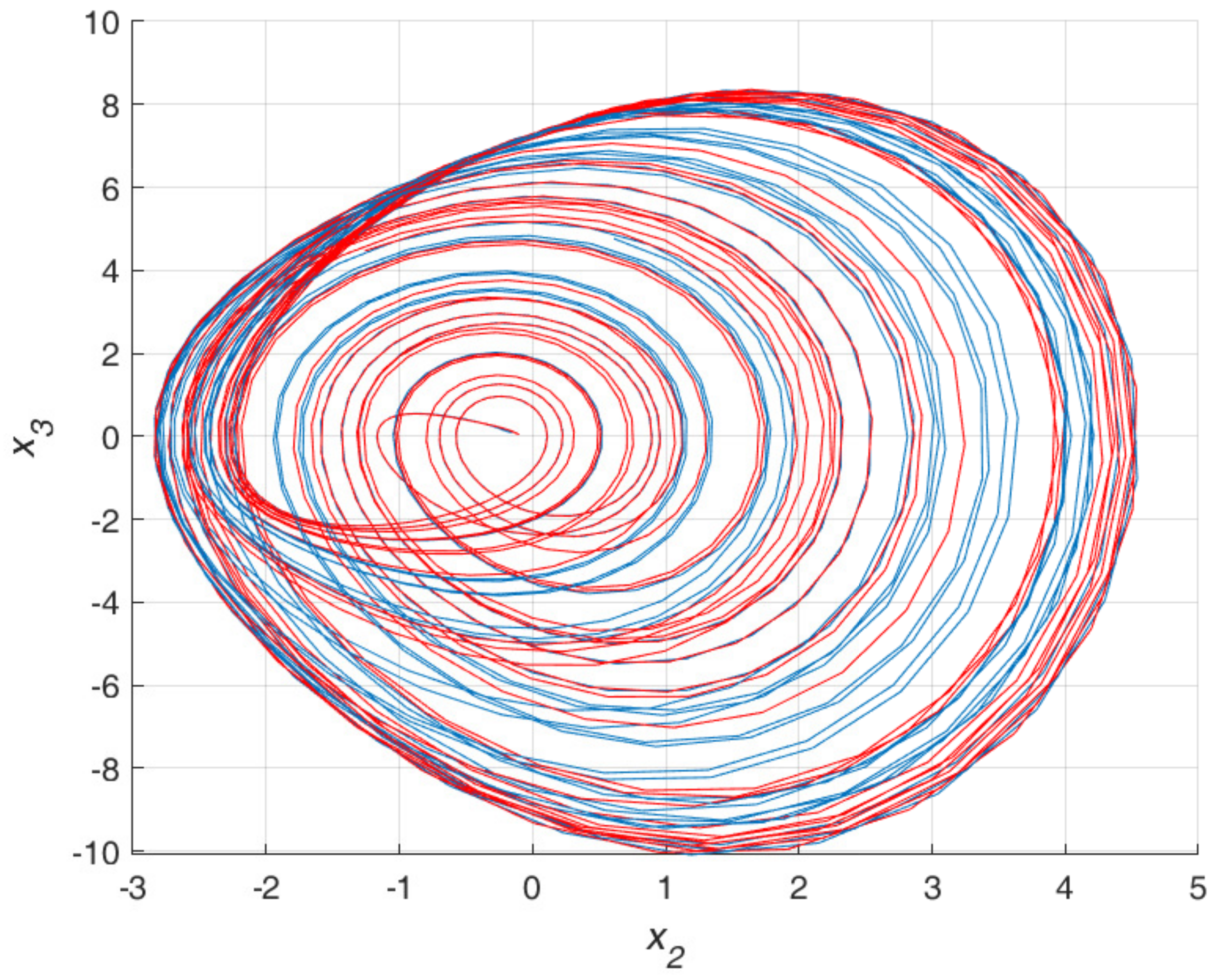
The presented system shows the infamous sensitive dependence on the initial conditions of the system. Figure 3 shows the phase portrait between x 2 & x 3 for two different sets of initial conditions for x 1 , x 2 , and   x 3 .

5.1. Lyapunov Exponent Test

Lyapunov Exponent test is commonly used for checking the existence of chaos in dynamical systems. If for any dynamical system, one of the Lyapunov exponents is positive, it indicates chaos. There are various algorithms available to find the Maximum Lyapunov Exponent (MLE) spectrum of a system described by differential (or difference) equations [38,39]. The basic equation for finding the Lyapunov exponents is given below [40].
λ ( x i ) = l i m n 1 n i = 0 n 1 l n f ( x i )
where, x i is the time series for the ith ODE.
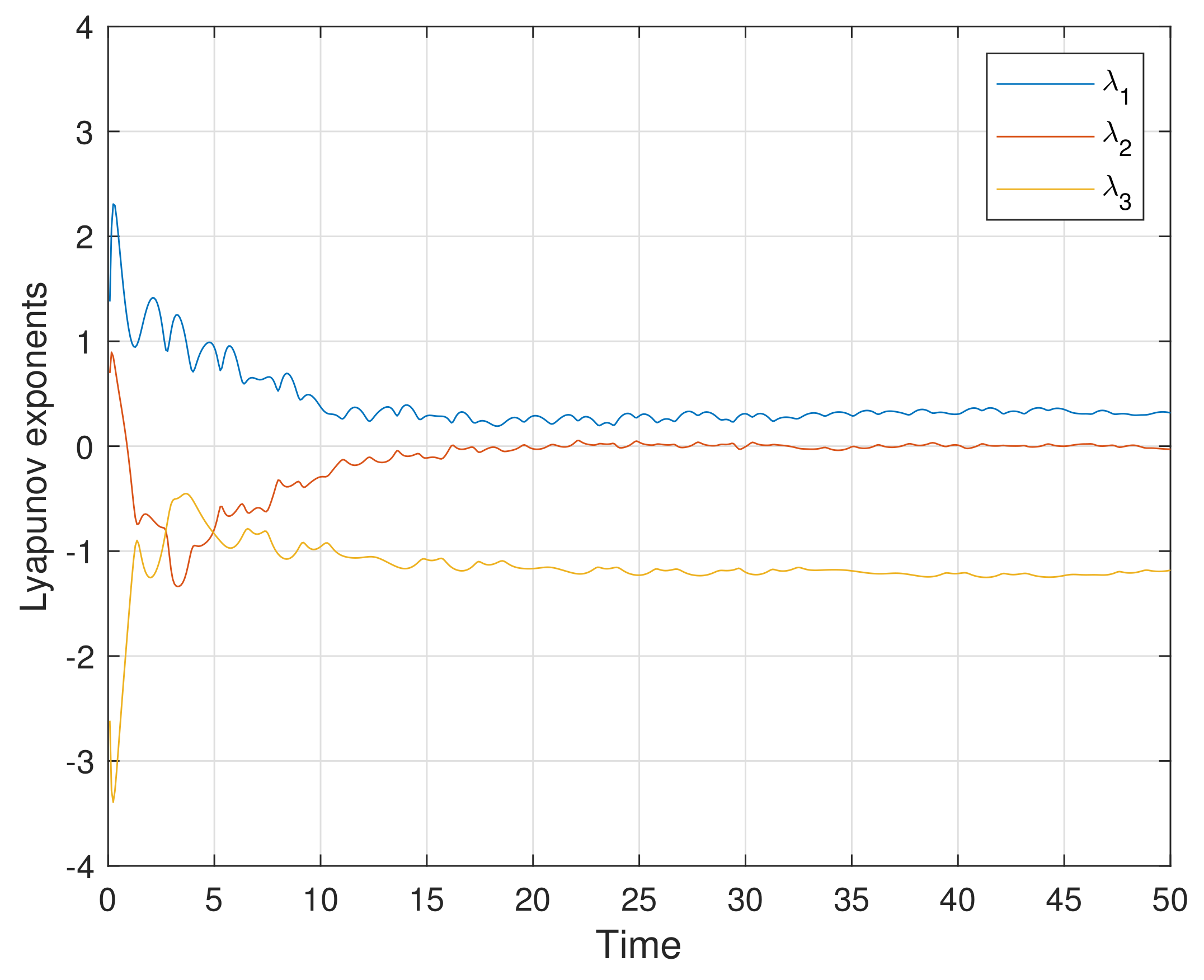
The dynamic Lyapunov spectrum of the proposed system, calculated using Wolf’s algorithm, for the control variable ‘ β = 5.535 ’ (chaotic case) is shown in Figure 4.
From Figure 4, it can be concluded that one of the Lyapunov spectra is positive. Since the positive Lyapunov exponent implies chaos, the system trajectory will diverge only in one direction, thereby confirming the single scroll attractor shown in Figure 3.

5.2. Bifurcation Diagram

The bifurcation diagram of the proposed system was found by varying control parameter ‘ β ’ from 5 to 12 with a step size of 0.01. The initial conditions were set to x 0 = [ 0.5   0.5   0 ] , and the period-doubling route to chaos was plotted in Figure 5 for all three states of the system.
It is to be noted that for β = 18 , the system has no oscillation, and this value is termed as the critical value. As β starts to decrease from 12 onward, the jerk based system starts to bifurcate from stable period 1 to period-doubling route to chaos shown in Figure 5.

5.3. Correlation Dimension

Every chaotic attractor has a fractal structure [41] and exhibits self-similarity (scale-invariance) quantified by computing fractal dimensions. Fractal dimension is a non-integer value that gives insights about the geometric form of the attractor. Correlation dimension provides a good estimate of the fractal dimension of the chaotic attractor. The correlation dimension can be found as
D c o r = log C r log ( r )
where, C r is called the correlation sum and is defined as
C r = 2 N   ( N 1 ) i = 1 N i = j + 1 N Θ r x i x j
here, ‘ Θ ’ is the heavy-side step function, ‘r’ is the radius, and N is the sample length. Figure 6 shows the graph between log( C r ) vs. log(r), the slope of which gives the correlation dimension approximately equal to 1.87.

5.4. Frequency Spectra

Frequency spectra is an essential visual tool to study chaos in a system. Many researchers have also used wavelet transform instead of frequency spectra as it can not only show the change in the system dynamics but also can point out the time at which such a change has occurred [42]. However, the size of the window plays a pivotal role in getting better visualization in the wavelet transform method. Frequency spectra method was preferred in this paper as it broadly illustrates the frequency dispersion distribution present in the system dynamics, which is enough for the visualization of chaos. Because of the highly chaotic region (5–5.5) in the bifurcation diagram Figure 5, the Fourier power spectrum was calculated only for four different cases. With every variation in the control parameter β , the presence of different attractors with the corresponding Fourier power spectrum is shown in Figure 7.
Clearly, one can see by visual inspection that there are 1, 2, and 4 periodic peaks in Figure 7b,e,h respectively corresponding to period 1, period 2 and period 4 attractors shown in Figure 7a,d,g. Also, an aperiodic power spectrum related to the chaotic attractor shown in Figure 7j is given in Figure 7k.

5.5. Poincare Section for Different Attractors

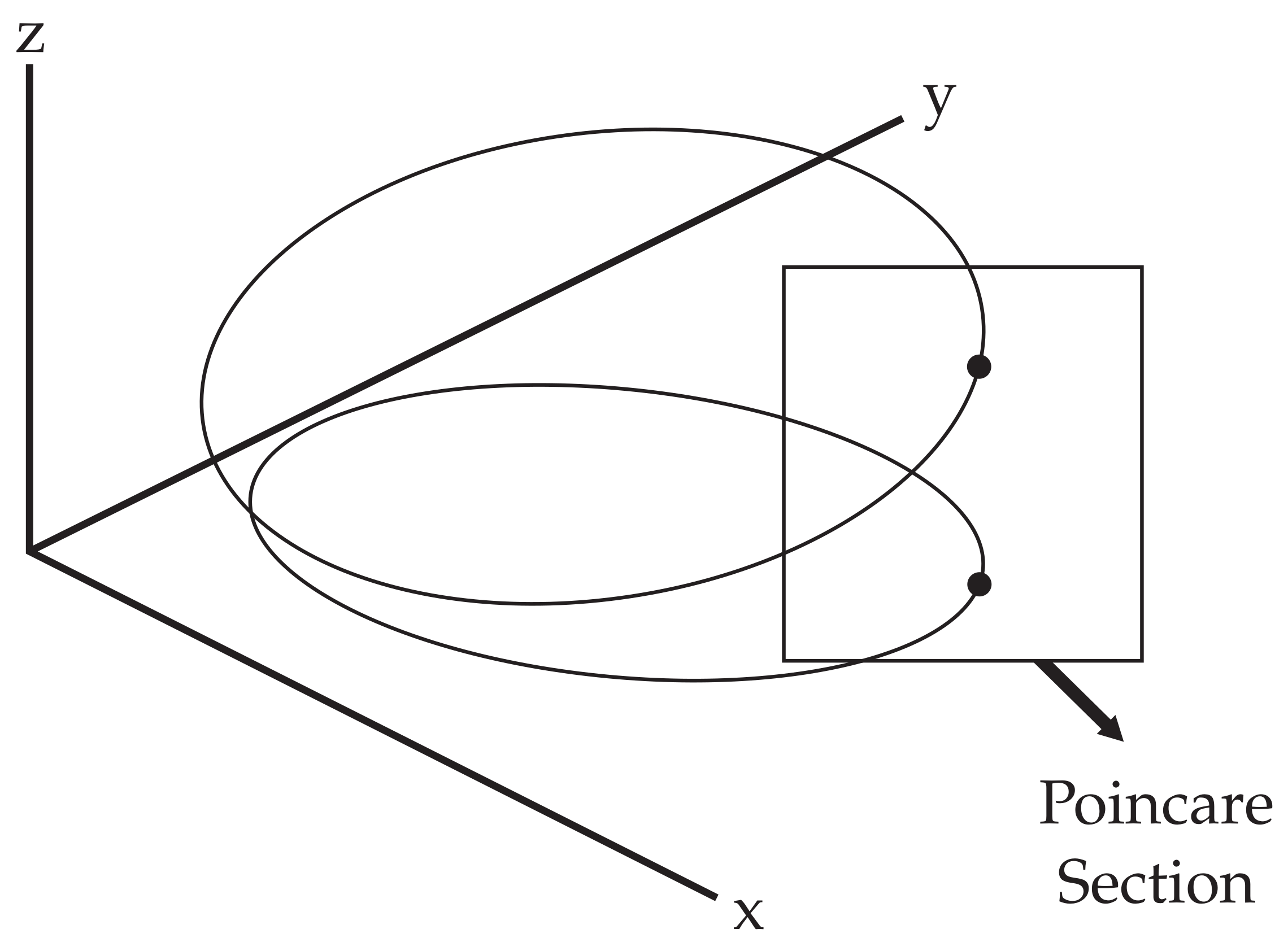
In certain cases, a periodic orbit can be confidently identified from a two-dimensional projection of an attractor (phase portraits). Nevertheless, this process typically does not help in yielding a convincing inference between quasi-periodic and strange attractors. The Poincare section, a two-dimensional plane intersecting the steady-state trajectories as seen in Figure 8, offers a better understanding of the periodicity. It transforms a continuous flow into a discrete mapping of time (Poincare map). Usually, only one direction of the crossing of the trajectory is considered. It is also possible to classify the behavior of the system by analyzing the stroboscobic distribution of the distinct points in the Poincare section. A finite number of points on the Poincare section which adequately represent the periodicity of the motion are observed for a periodic motion. For a quasi-periodic motion, a continuous line in the Poincare map is observed. If the motion is chaotic, because of the fractal character of the chaotic attractors, many irregularly points will be seen on the plane.
For visualization of the Poincare map for the proposed system, the plane x 2 = 0 was taken as a Poincare section and the trajectories that crosses this section from x 2 < 0 or x 2 > 0 were recorded. Figure 7 shows the Poincare section for a different variation of the control parameter β . In Figure 7c, the trajectories cut the section in a single line (positive section of the grid), characterized by the quasi period-1 attractor given in Figure 7a. Similarly, the Poincare section for quasi period-2 and quasi period-4 are given in Figure 7f,i, characterized by the two or four straight lines in the Poincare section. Finally, in Figure 7l, the points are located irregularly on the Poincare section, the behavior of the system can be termed as chaotic as evident from the phase portrait given in Figure 7j.

6. Experimental Setup

To validate the numerical results of the proposed discrete map based jerk chaotic system, an electrical circuit was made. Op-Amps were used to implement the system of ODEs given by Equations (7), (8) and (10) [38]. Two analog multipliers ICs (AD633JR) were required in series to get the cubic term in Equation (10). It has four inputs ( X 1 , X 2 , Y 1   &   Y 2 ) and two outputs ( W   &   Z ). The output is given as W = ( X 1 X 2 ) ( Y 1 Y 2 ) / 10 + Z . It can be shown that the Equations (7), (8) and (10) [38] can be easily transformed into the following set of Equations (17)–(19).
d X 1 d t = X 2 RC
d X 2 d t = X 3 RC
d X 3 d t = X 1 R 1 C X 2 R 2 C X 3 R 3 C X 1 3 600 R 4 C
Using a time constant of 1 × 10 4 , the control parameters in terms of resistance and capacitor can be calculated from the following relations while maintaining the critical relation of R 4 = R / 100
α = 1 × 10 4 R 1 C = 1 ,         β = 1 × 10 4 R 2 C = V a r i a b l e ,
σ = 1 × 10 4 R 3 C = 6 ,         γ = 1 × 10 4 600 R 4 C = 6
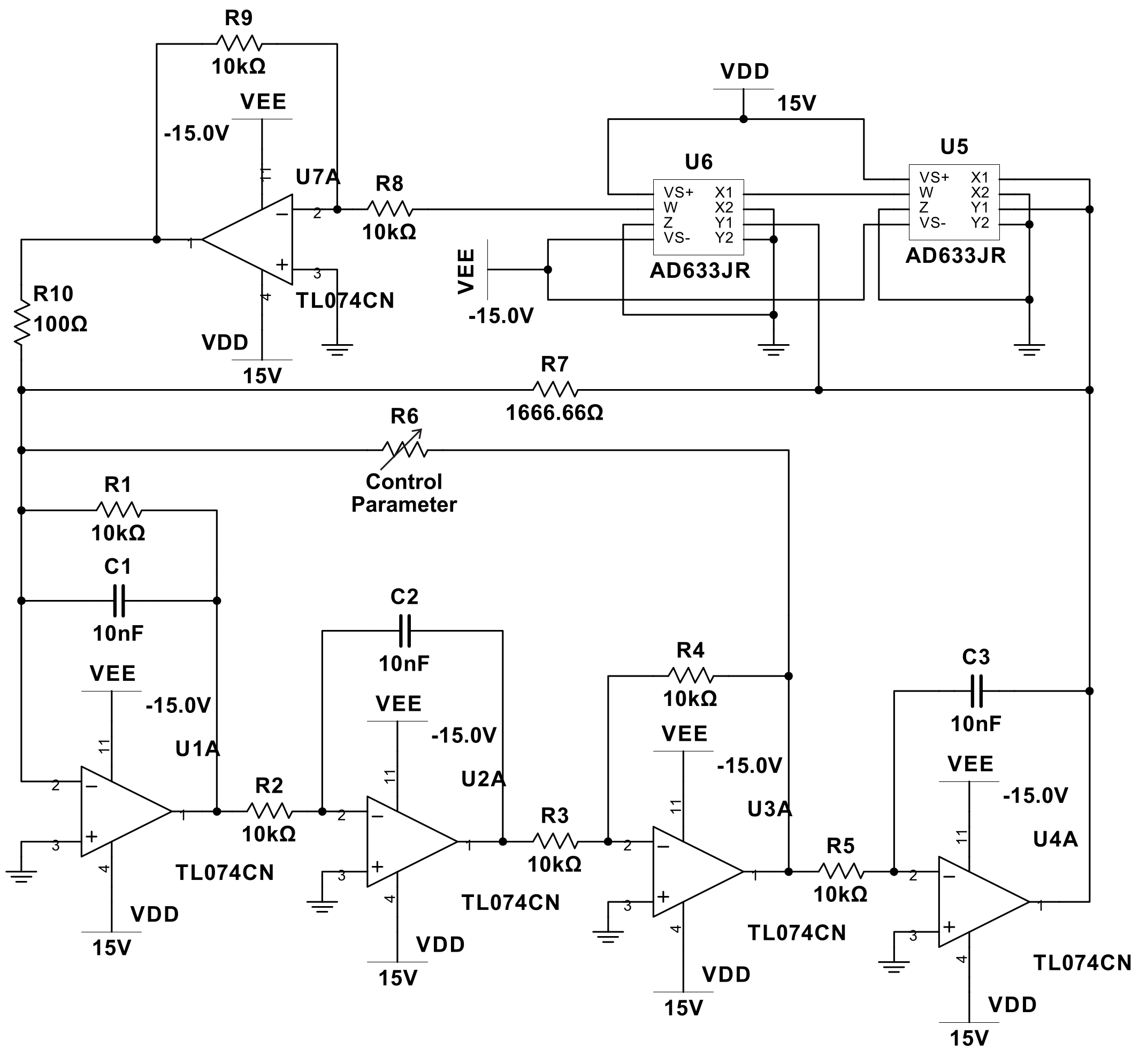
NI Multisim was used to simulate the electrical circuit before implementing it on the breadboard. The schematic of the proposed circuit is shown in Figure 9.
Using appropriate time scaling, the output voltage of U 1 A ( x 3 ) and U 3 A ( x 2 ) are directly monitored using a two-channel digital oscilloscope shown in Figure 10.

Experimental Verification

The circuit schematic, given in Figure 9, was implemented on a breadboard by using TL074CN fast switching Op-Amps with high precision resistors, as shown in Figure 11. The values for the components of the circuit are tabulated in Table 1. Variable resistor ‘R6’ is used to replicate the effect of change of β in the numerical simulations. The proposed system shows period-doubling route to chaos as the value of R6 increases beyond 1 k Ω . Table 2 summarizes the various attractor obtained by changing the control resistance ‘R6’.
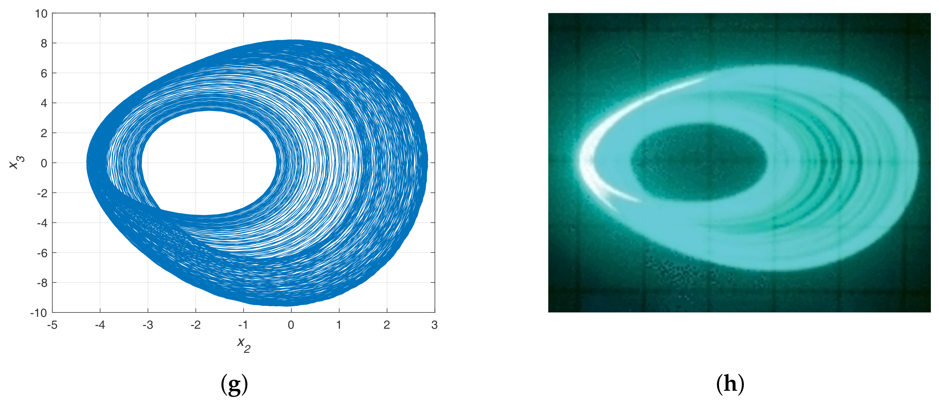
Figure 12 shows a comparison between the numerical (left) and hardware (right) results. Period 1 (limit cycle) attractor was obtained by setting the control resistor R6 to 1112 Ω , similarly increasing the value of R6 to 1667 Ω gives the period 2 attractor, R6 = 1715 Ω corresponds to period 4 attractor finally, R6 = 1807 Ω gives the chaotic attractor.

7. Discussion

Nonlinear dynamical systems with complex and irregular behavior can be characterized using chaotic time-series analysis. This method aims to study characteristics of the deterministic dynamical systems with different tools, describe them with a proper model, and predict future values. Since all practical systems are nonlinear, the analysis of a nonlinear dynamical system involves linearization. But, these hidden non-linearities produce strange behavior. Most of the engineering curriculum emphasizes the analysis of a system based on linear system theory [36], thereby oversimplifying the wide range of fascinating dynamic responses.
During the last century, many chaos theorists highlighted the educational importance of chaotic dynamical systems to pay off the conventional linear thinking established through prolonged learning techniques [43,44,45]. Nonlinear systems can exhibit complicated dynamics that disobey almost every law studied under linear systems. Because of several equilibrium points for different initial conditions, it becomes impossible to predict their long-term behavior. This property of the nonlinear system, which happens to be considered noise as it appears random in the time domain, can find its application in almost every scientific field. Overall, chaos theory enables us to embrace all the weirdness of life rather than suppressing it.
In this paper, a novel chaotic system is presented based on the simple jerk equation. The discrete sine map was added as a nonlinear function to the jerk equation and approximated using the Taylor series expansion. The proposed system simulation was carried out in MATLAB/NI Multisim first and later verified by hardware implemented using simple Op-Amps with analog multipliers.

8. Conclusions

This paper studied a simple nonlinear dynamical system based on a jerk equation with a discrete-time map. The system can show periodic as well as aperiodic behavior based on the value of the control parameter. MATLAB simulations were used to verify the theoretical aspects of the proposed system. An electronic circuit of the nonlinear system was made in NI Multisim using basic electrical engineering knowledge. Further, it was implemented in real-time on a breadboard to verify the system’s chaotic nature. A fair consensus was seen between the simulation & experimental results. High frequency range, quasi-periodicity, autonomous chaotic existence, and low power consumption are some of the important aspects of the design, which can find applications in cryptography, secure communication, compressed sensing, biology, weather forecasting, mechanical engineering etc.

Author Contributions

Conceptualization, M.H.A. and M.K.; methodology, M.H.A.; software, M.H.A.; validation, M.H.A. and M.K.; formal analysis, M.H.A.; investigation, M.H.A., M.K. and M.A.A.; resources, A.E.H. and M.K.; writing—original draft preparation, M.H.A.; writing—review and editing, A.E.H., M.K. and M.A.A.; supervision, M.K.; project administration, M.K.; funding acquisition, A.E.H., M.K. and M.A.A. All authors have read and agreed to the published version of the manuscript.

Funding

The authors would like to acknowledge the support provided by King Fahd University of Petroleum & Minerals through the Research Group funded project #DF191004. The authors also acknowledge the funding support by King Abdullah City for Atomic and Renewable Energy (K.A. CARE), Energy Research & Innovation Center (ERIC) at KFUPM.

Institutional Review Board Statement

Not applicable.

Informed Consent Statement

Not applicable.

Data Availability Statement

The data presented in this study are available within the article.

Acknowledgments

The authors would like to acknowledge the support provided by King Fahd University of Petroleum & Minerals through the Research Group funded project #DF191004. The authors also acknowledge the funding support by King Abdullah City for Atomic and Renewable Energy (K.A. CARE), Energy Research & Innovation Center (ERIC) at KFUPM. We would like to acknowledge Anas Muhammad Rafiq for his assistance with the experimental verification.

Conflicts of Interest

The authors declare no conflict of interest.

Abbreviations

The following abbreviations are used in this manuscript:
MLEMaximum Lyapunov Exponent
ODEOrdinary differential equation
SNFSSaturated Nonlinear Function Series
DOFDegree of freedom
H.O.T.Higher-order terms
DSRDeanship of Scientific Research
K. A. CAREKing Abdullah City of Atomic & Renewable Energy

References

  1. Li, T.Y.; Yorke, J.A. Period Three Implies Chaos. Am. Math. Mon. 1975, 82, 985–992. [Google Scholar] [CrossRef]
  2. Oestreicher, C. A History of Chaos Theory. Dialogues Clin. Neurosci. 2007, 9, 279. [Google Scholar] [PubMed]
  3. Sundar, S.; Minai, A.A. Synchronization of Randomly Multiplexed Chaotic Systems with Application to Communication. Phys. Rev. Lett. 2000, 85, 5456. [Google Scholar] [CrossRef] [PubMed] [Green Version]
  4. Kotulski, Z.; Szczepański, J.; Górski, K.; Paszkiewicz, A.; Zugaj, A. Application of Discrete Chaotic Dynamical Systems in Cryptography—DCC Method. Int. J. Bifurc. Chaos 1999, 9, 1121–1135. [Google Scholar] [CrossRef]
  5. Krysko, A.; Awrejcewicz, J.; Zhigalov, M.; Pavlov, S.; Krysko, V. Nonlinear behaviour of different flexible size-dependent beams models based on the modified couple stress theory. Part 2. Chaotic dynamics of flexible beams. Int. J. Non-Linear Mech. 2017, 93, 106–121. [Google Scholar] [CrossRef]
  6. Awrejcewicz, J.; Krysko, A.; Kutepov, I.; Zagniboroda, N.; Dobriyan, V.; Krysko, V. Chaotic dynamics of flexible Euler-Bernoulli beams. Chaos Interdiscip. J. Nonlinear Sci. 2013, 23, 043130. [Google Scholar] [CrossRef]
  7. Arshad, M.H.; Kassas, M. A Chaos Based SVPWM technique for B4 Inverter fed Two-Phase Symmetric Induction Motor for THD & EMI improvement at Low Modulation Index. In Proceedings of the 2019 IEEE Texas Power and Energy Conference (TPEC), College Station, TX, USA, 7–8 February 2019; pp. 1–6. [Google Scholar]
  8. Ian, S. Does God Play Dice?: The Mathematics of Chaos; Blackwell Publishing: Hoboken, NJ, USA, 1989; p. 393. [Google Scholar]
  9. Sayed, W.S.; Radwan, A.G.; Fahmy, H.A. Chaotic Systems Based on Jerk Equation and Discrete Maps with Scaling Parameters. In Proceedings of the IEEE 2017 6th International Conference on Modern Circuits and Systems Technologies (MOCAST), Thessaloniki, Greece, 4–6 May 2017; pp. 1–4. [Google Scholar]
  10. Eckmann, J.P.; Ruelle, D. Ergodic Theory of Chaos and Strange Attractors. In The Theory of Chaotic Attractors; Springer: Berlin/Heidelberg, Germany, 1985; pp. 273–312. [Google Scholar]
  11. Sprott, J. Some Simple Chaotic Jerk Functions. Am. J. Phys. 1997, 65, 537–543. [Google Scholar] [CrossRef]
  12. Kennedy, M.P. Experimental Chaos from Autonomous Electronic Circuits. Philos. Trans. R. Soc. Lond. Ser. A Phys. Eng. Sci. 1995, 353, 13–32. [Google Scholar]
  13. Lakshmanan, M.; Murali, K. Experimental Chaos from Non-Autonomous Electronic Circuits. Philos. Trans. R. Soc. Lond. Ser. A Phys. Eng. Sci. 1995, 353, 33–46. [Google Scholar]
  14. Linsay, P.S. Period Doubling and Chaotic Behavior in a Driven Anharmonic Oscillator. Phys. Rev. Lett. 1981, 47, 1349. [Google Scholar] [CrossRef]
  15. Newcomb, R.; Sathyan, S. An RC Op-Amp Chaos Generator. IEEE Trans. Circuits Syst. 1983, 30, 54–56. [Google Scholar] [CrossRef]
  16. Matsumoto, T.; Chua, L.; Komuro, M. The Double Scroll Bifurcations. Int. J. Circuit Theory Appl. 1986, 14, 117–146. [Google Scholar] [CrossRef]
  17. Azzouz, A.; Duhr, R.; Hasler, M. Transition to Chaos in a Simple Nonlinear Circuit Driven by a Sinusoidal Voltage Source. IEEE Trans. Circuits Syst. 1983, 30, 913–914. [Google Scholar] [CrossRef]
  18. Kennedy, M.P. Chaos in the Colpitts Oscillator. IEEE Trans. Circuits Syst. I Fundam. Theory Appl. 1994, 41, 771–774. [Google Scholar] [CrossRef]
  19. Tekam, R.B.W.; Kengne, J.; Kenmoe, G.D. High Frequency Colpitts’ Oscillator: A Simple Configuration for Chaos Generation. Chaos Solitons Fractals 2019, 126, 351–360. [Google Scholar] [CrossRef]
  20. Madan, R.N. Chua’s Circuit: A Paradigm for Chaos; World Scientific Publishing Co.: Singapore, 1993. [Google Scholar]
  21. Prebianca, F.; Marcondes, D.W.; Albuquerque, H.A.; Beims, M.W. Exploring an Experimental Analog Chua’s Circuit. Eur. Phys. J. B 2019, 92, 134. [Google Scholar] [CrossRef]
  22. Tchitnga, R.; Nguazon, T.; Fotso, P.H.L.; Gallas, J.A. Chaos in a Single Op-Amp–based Jerk Circuit: Experiments and Simulations. IEEE Trans. Circuits Syst. II Express Briefs 2015, 63, 239–243. [Google Scholar] [CrossRef] [Green Version]
  23. Chiu, R.; López-Mancilla, D.; Castañeda, C.E.; Orozco-López, O.; Villafaña-Rauda, E.; Sevilla-Escoboza, R. Design and Implementation of a Jerk Circuit using a Hybrid Analog–Digital System. Chaos Solitons Fractals 2019, 119, 255–262. [Google Scholar] [CrossRef]
  24. Radwan, A.; Soliman, A.M.; Elwakil, A.S. 1-D Digitally-Controlled Multiscroll Chaos Generator. Int. J. Bifurc. Chaos 2007, 17, 227–242. [Google Scholar] [CrossRef]
  25. Bao, B.; Zhou, G.; Xu, J.; Liu, Z. Multiscroll Chaotic Attractors from a Modified Colpitts Oscillator Model. Int. J. Bifurc. Chaos 2010, 20, 2203–2211. [Google Scholar] [CrossRef]
  26. Zidan, M.A.; Radwan, A.G.; Salama, K.N. Controllable V-shape multiscroll butterfly attractor: System and circuit implementation. Int. J. Bifurc. Chaos 2012, 22, 1250143. [Google Scholar] [CrossRef] [Green Version]
  27. Sánchez-López, C.; Trejo-Guerra, R.; Munoz-Pacheco, J.; Tlelo-Cuautle, E. N-Scroll Chaotic Attractors from Saturated Function Series Employing CCII+ s. Nonlinear Dyn. 2010, 61, 331–341. [Google Scholar] [CrossRef] [Green Version]
  28. Sánchez López, C. A 1.7 MHz Chua’s Circuit using VMs and CF+ s. Rev. Mex. De Física 2012, 58, 86–93. [Google Scholar]
  29. Ortega-Torres, E.; Sánchez-López, C.; Mendoza-López, J. Frequency Behavior of Saturated Nonlinear Dunction Series Based on Opamps. Rev. Mex. Física 2013, 59, 504–510. [Google Scholar]
  30. Sprott, J.C. A New Class of Chaotic Circuit. Phys. Lett. A 2000, 266, 19–23. [Google Scholar] [CrossRef]
  31. Komuro, M. Birth and Death of the Double Scroll. In Proceedings of the 1985 24th IEEE Conference on Decision and Control, Fort Lauderdale, FL, USA, 11–13 December 1985; pp. 456–460. [Google Scholar]
  32. Matsumoto, T.; Chua, L.; Komuro, M. Birth and Death of the Double Scroll. Phys. D Nonlinear Phenom. 1987, 24, 97–124. [Google Scholar] [CrossRef]
  33. Patidar, V.; Sud, K. Bifurcation and Chaos in Simple Jerk Dynamical Systems. Pramana 2005, 64, 75–93. [Google Scholar] [CrossRef]
  34. Kengne, J.; Njikam, S.; Signing, V.F. A Plethora of Coexisting Strange Attractors in a Simple Jerk System with Hyperbolic Tangent Nonlinearity. Chaos Solitons Fractals 2018, 106, 201–213. [Google Scholar] [CrossRef]
  35. Kengne, J.; Mogue, R.L.T.; Fozin, T.F.; Telem, A.N.K. Effects of Symmetric and Asymmetric Nonlinearity on the Dynamics of a Novel Chaotic Jerk Circuit: Coexisting Multiple Attractors, Period Doubling Reversals, Crisis, and Offset Boosting. Chaos Solitons Fractals 2019, 121, 63–84. [Google Scholar] [CrossRef]
  36. Tagne, R.M.; Kengne, J.; Negou, A.N. Multistability and chaotic dynamics of a simple Jerk system with a smoothly tuneable symmetry and nonlinearity. Int. J. Dyn. Control 2019, 7, 476–495. [Google Scholar] [CrossRef]
  37. Giakoumis, A.; Volos, C.K.; Stouboulos, I.N.; Kyprianidis, I.M.; Nistazakis, H.E.; Tombras, G.S. Implementation of a Laboratorybased Educational Tool for Teaching Nonlinear Circuits and Chaos. In Advances and Applications in Chaotic Systems; Springer: Berlin/Heidelberg, Germany, 1995; pp. 379–407. [Google Scholar]
  38. Chen, C.T. Linear System Theory and Design; Oxford University Press, Inc.: Oxford, UK, 1998. [Google Scholar]
  39. Tancredi, G.; Sánchez, A.; Roig, F. A Comparison Between Methods to Compute Lyapunov Exponents. Astron. J. 2001, 121, 1171. [Google Scholar] [CrossRef]
  40. Greiner, W. Lyapunov Exponents and Chaos. In Classical Mechanics: Systems of Particles and Hamiltonian Dynamics; Springer: Berlin/Heidelberg, Germany, 2010; pp. 503–516. [Google Scholar]
  41. Sprott, J.C. Chaos and Time-Series Analysis; Oxford University Press, Inc.: Oxford, UK, 2003; Volume 69. [Google Scholar]
  42. Awrejcewicz, J.; Krysko, A.; Soldatov, V.; Krysko, V. Analysis of the nonlinear dynamics of the Timoshenko flexible beams using wavelets. J. Comput. Nonlinear Dyn. 2012, 7, 011005. [Google Scholar] [CrossRef]
  43. Seshadri, H.; Verma, K. The Embedding Theorems of Whitney and Nash. Resonance 2016, 21, 815–826. [Google Scholar] [CrossRef]
  44. May, R.M. Simple Mathematical Models with very Complicated Dynamics. In The Theory of Chaotic Attractors; Springer: Berlin/Heidelberg, Germany, 2004; pp. 85–93. [Google Scholar]
  45. Strogatz, S.H. Nonlinear Dynamics and Chaos: With Applications to Physics, Biology, Chemistry, and Engineering; CRC Press: Boca Raton, FL, USA, 2018. [Google Scholar]
Figure 1. Chaotic invariants for approximated discrete–time Sine Map: (a) Bifurcation Diagram, (b) Lyapunov Exponent, (c) Cobweb Plot, (d) Pseudo Space Trajectory, (e) Time Series.
Applsci 11 00437 g001
Figure 2. Time Series for for x 3 : Presence of multiple attractors in the proposed discrete-time map based chaotic jerk system.
Applsci 11 00437 g002
Figure 3. Sensitivity dependence on the initial conditions: Two sets of initial conditions (0.1, 0.1, 0.5) & (0.5, 0.5, 0) with β = 5.535 .
Applsci 11 00437 g003
Figure 4. Maximum Lyapunov Exponent spectrum for the proposed discrete–time map based chaotic jerk system.
Applsci 11 00437 g004
Figure 5. Bifurcation Diagram: (a) local maxima of x 1 vs. Control Parameter β , (b) local maxima of x 2 vs. Control Parameter β , (c) local maxima of x 3 vs. Control Parameter β .
Applsci 11 00437 g005
Figure 6. C r vs. l n ( r ) plot for calculating the Correlation Dimension.
Applsci 11 00437 g006
Figure 7. Attractor (left), Frequency Spectrum (center), & Poincare Section: (right) (ac) Period 1 or Limit Cycle Attractor case for β = 9 , (df) Period 2 Attractor case for β = 6 , (gi) Period 4 Attractor case for β = 5.84 , (jl) Chaotic Attractor case for β = 5.535 .
Applsci 11 00437 g007
Figure 8. Graphical representation of calculating stroboscopic distribution by finding the points of intersection of the phase trajectories with the Poincare Section.
Applsci 11 00437 g008
Figure 9. The circuit schematic for the proposed discrete–time map based jerk chaotic system.
Applsci 11 00437 g009
Figure 10. NI Multisim’s digital oscilloscope output for the proposed circuit with R 6 = 1807   Ω .
Applsci 11 00437 g010
Figure 11. Experimental Setup: (a) Oscilloscope, (b) Controlled DC Power Supply, (c) Breadboard Implementation.
Applsci 11 00437 g011
Figure 12. Numerical (left) vs. Experimental (right) results: (a,b) Period 1 or Limit Cycle Attractor case for β = 9   &   R 6 =   1112   Ω , (c,d) Period 2 Attractor case for β = 6   &   R 6 = 1667   Ω , (e,f) Period 4 Attractor case for β = 5.84   &   R 6 = 1715   Ω , (g,h) Chaotic Attractor case for β = 5.535   &   R 6 = 1807   Ω .
Applsci 11 00437 g012aApplsci 11 00437 g012b
Table 1. Parameters of Experimental Setup.
ParameterValueUnit
R1–R5, R8–R910 k Ω
R 7 1.67 k Ω
R 10 100 Ω
C1–C310 nF
V D D 15V
V E E –15V
Table 2. Summary of Different Attractor with the variation of Control Resistance R6.
Sr. No.Value of R6Attractor Type
11112 Ω Period 1
21667 Ω Period 2
31715 Ω Period 4
41807 Ω Chaotic Attractor
Publisher’s Note: MDPI stays neutral with regard to jurisdictional claims in published maps and institutional affiliations.