Abstract
As contemporary emerging materials, fiber-reinforced plastics/polymers (FRP) are widely used in aerospace automotive industries and in other fields due to their high strength-to-weight ratio, high stiffness-to-weight ratio, high corrosion resistance, low thermal expansion and other properties. Drilling is the most frequently used process in industrial operation for polymer composite laminates, owing to the need for joining structures. However, it is a great challenge for operators to drill holes in FRP materials, due to the non-homogenous and anisotropic properties of fibers. Various damages, such as delamination, hole shrinkage, and burr and tool wear, occur due to the heterogeneous and anisotropic nature of composite laminates. Therefore, in this study, carbon fiber reinforced polymer (CFRP)/aramid fiber reinforced polymer (AFRP) hybrid composites (C-AFRP) were successfully synthesized, and their drilling characteristics, including burr generation and tool wear, were also mainly investigated. The drilling characteristics of CFRP and C-AFRP were compared and analyzed for the first time under the same operating conditions (cutting tool, spindle speed, feed rate). The experimental results demonstrated that C-AFRP had higher tensile strength and good drilling characteristics (low thrust and less tool wear) compared with CFRP. As a lightweight and high-strength structural material, C-AFRP hybrid composites have great potential applications in the automobile and aerospace industries after the slight processing of burrs generated during drilling.
1. Introduction
With the continuous development of science and technology, people no longer pursue traditional metal materials, such as copper, iron, steel, and aluminum. Ceramics, alloys and other composite materials have attracted attention from many researchers in recent decades [1,2]. Especially, in recent decades, people have developed higher expectations of materials with respect to high strength and low weight, and traditional metal materials are far from meeting these requirements. Therefore, it is necessary to urgently develop a new composite material with high strength that is light weight and antiseptic [2].
Composite materials are mechanical engineering materials composed of two or more different materials with different physical forms or chemical compositions. Various constituent materials can complement each other in performance and produce a synergistic effect, so that the comprehensive performance of composite materials is better than that of the raw materials, so as to meet various requirements [3]. Generally speaking, the composition of composite materials includes two parts: matrix and reinforcement; the three dimensional region with specific characteristics between these two constituents is known as the interphase region [4,5]. Metallic, polymer and ceramic materials are commonly used as the matrices, while particles or crystal filaments in the form of fiber are commonly used as the reinforcements. Various chemical compositions and microstructural arrangements are possible in each matrix category. In general, fibers are the principal load-carrying members, while the surrounding matrix keeps them in the desired location and orientation [1,4]. This kind of composite material, formed by high-strength fibers and moduli embedded in or bonded to a matrix with distinct interfaces, is called a fiber-reinforced composite (FRC). FRC can be classified into four groups, according to their matrices—metal matrix composites (MMCs), ceramic matrix composites (CMCs), carbon/carbon composites (C/C), and polymer matrix composites (PMCs) or polymeric composites [6]. Among these materials, fiber-reinforced plastics/polymers (FRP) are either comparable to or better than many traditional metallic materials (e.g., steel and aluminum alloys), due to their high strength-to-weight ratio, stiffness-to-weight ratio, fracture toughness and corrosion resistance [7,8]. Three common FRP mainly include carbon FRP (CFRP), glass FRP (GFRP), and aramid FRP (AFRP). FRP is widely used in the construction, military, marine, aerospace, and automotive industries, and other fields based on their advantages, such as low density, high damping ability, high strength, high thermal resistance, low thermal expansion, stability, good corrosion resistance, etc. [8,9,10]. Therefore, the use of lightweight and elevated strength composites will become the mainstream of industrial design and manufacturing in the future. Especially in the field of aerospace and the automobile industry, the use of lightweight and high-strength materials has greatly help to reduce fuel consumption and improve safety.
However, FRP materials have various machining failures, including delamination (separation of laminated layers), burrs, fiber pull out, fiber break, uncut fibers, melting of the matrix, adhesion of materials to drill, and sub-surface failures, due to the non-homogeneity, multi-phase structure and anisotropic nature of the composites [11,12,13]. The common problems of finish machining and surface integrity often occur when using conventional processing tools, such as drilling, cutting and milling to FRP. This leads to the scrapping of a large number of workpieces, which is also one of the main reasons for the high machining cost of CFR. Among various machining operations, drilling is the most frequently used process in industrial operation for polymer composite laminates, owing to the need for joining structures in various industries, such as the automotive, aerospace, marine and oil industries. For example, the Airbus A350 aircraft (large-size CFRP composite components) needs about 55,000 holes in the manufacturing process [13]. Some drilling damage, such as delamination, has a negative impact on the load-carrying capacity of the structure, which directly leads to the decrease in the durability of the material [14]. In addition, the cutting tool is also very easy to wear in the drilling of FRP materials, because FRP is a difficult-to-cut material, due to the non-homogenous and anisotropic properties of carbon fiber [15,16,17]. The machinability of FPR materials mainly depends on the fiber matrix interface interaction, fiber orientations, cutting directions and tool wear. Moreover, different machining parameters, cutting tools, tool coatings, and lubrication modes have different damage degrees on tool wear and composite laminates [18,19,20,21,22]. Therefore, many researchers, in general, have sought to determine the optimum cutting parameters to avoid the above failures [23,24].
Karpat et al. [25] found that delamination in fabric woven CFRP laminates is observed by SEM images, which is closely related to the condition of the diamond coating. They also pointed out that increasing the feed rate and rotational speed can protect diamond-coated carbide bits and improve hole quality. Delamination is one of the most serious defects in the processing of FRP materials, which is an inter-laminar or inter-ply failure phenomenon. Delamination directly affects the mechanical properties of FPR materials and shortens their fatigue lives, hence limiting their further applications [10]. Murphy et al. [26] have investigated the effects of three tool types (uncoated, TiN coated and DLC coated) on tool wear, delamination and spalling during drilling of carbon fiber-reinforced epoxy, which cause the rise in thrust force and torque with increasing tool wear. The coatings were not found to be helpful in reducing tool wear or damage to composites. Durão et al. [27] reported that adequate tool selection can minimize the delamination of CFRP and GFRP composite materials during drilling operations, and a low feed rate can reduce axial thrust force and is more suitable for laminated drilling. They also pointed out that the geometry and type of the tool have an impact on feed rate, thrust force and delamination around the hole. Davim and Reis [28] investigated the influence of cutting parameters, such as cutting velocity and feed rate, on power, specific cutting pressure and delamination in the drilling of CFPR materials. The authors concluded that the feed rate has a greater influence on power and specific cutting pressure, so the delamination increases with the feed. By changing the action point and cutting direction, Jia et al. [29] found that upward cutting can cut fibers better than cutting from the machined side to the drill exit in cutting CFRP, and the novel intermittent-sawtooth drill structure effectively reduces burrs and delamination. Geng et al. [8] also reviewed the formation mechanism of delamination drilling FPR materials and reported that the drilling-induced delamination usually occurs at the hole entry and hole exit of the drilled hole periphery. The hole entry delamination (peel-up delamination) is mainly related to the flute shape, helical angle, drilling torque and drill vibration, while the hole exit delamination (push-out delamination) is mainly related to the thrust force, interface quality of the laminates and process conditions. Many other researchers have also studied delamination during drilling FPR materials [30,31,32]. By reviewing the above literature, it is found that most of the studies mainly focus on delamination during drilling FPR materials, but the research on uncut fibers and tool wear is still not clear, and there is a deficit in the existing knowledge of the wear mechanisms, including factors that determine the wear resistance of the tool, especially research on hybrid FPR materials, which is still in the exploratory stage.
At present, among the three common FRP materials, CFRP is widely used in high-class cars, due to its excellent “weight-loss benefit”. However, due to its low energy absorption and long production cycle time, CFRP cannot be widely used in ordinary vehicles. Tanaka et al. [33] found that the use of hybrid CFRP materials can improve the above shortcomings. Cheon et al. [34] also reported that carbon/aramid hybrid composites had better stab resistance performances compared to the CFRP, especially the [C8/A8] hybrid composite, which had the best stab resistance without penetration. To further investigate the drillability of hybrid FPR materials, the carbon/aramid hybrid composites (CFRP/AFRP) were successfully synthesized in this study. In addition, the burr formation and tool wear were also comparatively analyzed in drilling CFRP and hybrid CFRP/AFRP (C-AFRP) composites.
2. Materials and Methods
2.1. Test Materials
CFRP and C-AFRP laminates with a stacking sequence of [0°/90°] having a thickness of 6 mm and dimensions 130 mm × 130 mm were used as the workpiece materials. The CFRP laminates were thermoplastic fabricated in an autoclave at 140 °C and 5.89 MPa for 60 min by using plain woven carbon fiber prepreg (WSN-3K, SK Chemicals Co., Ltd., Seongnam-si, Korea). The C-AFRP laminates were thermoplastic fabricated in a vacuum autoclave at 120 °C and 0.5 MPa for 90 min by using SYT45-3K carbon fiber (Zhongfu Shenying Carbon Fiber Group Co., Ltd., Lianyungang, Jiangsu, China) and TF 100 aramid fiber (Taekwang Industrial Co., Ltd., Seoul, Korea). Images of CFRP and C-AFRP laminates are shown in Figure 1.
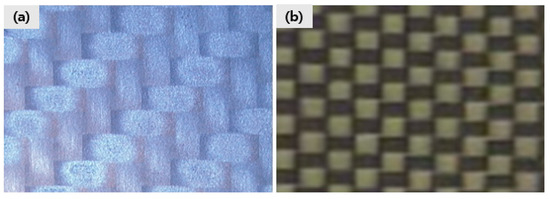
Figure 1.
Images of (a) CFRP and (b) C-AFRP.
2.2. Machine Setup and Drilling Experiment Details
A series of experiments were carried out on a bed-type computer numerical control (CNC) machine (HISUPER-4, Hwacheon, Co., Ltd., Seoul, Korea). The CNC machine is a 3-axis model consisting of linear motors and FANUC 0-Mate controller with a maximum spindle speed and power of 10,000 rpm and 7.5kW, respectively. The main CNC machine specifications are displayed in Table 1. The schematic of the drilling experimental setup is shown in Figure 2. A Kistler 9271A piezo-electric type force-torque dynamometer was employed to measure thrust force and torque during the drilling experiment. A complementary Kistler 5017A 8-channel charge amplifier was connected to the force dynamometer to amplify the output charge signals. All data were acquired and recorded by an A/D card converter and was further analyzed by software on a PC computer. The tested laminate was clamped in a jig attached to a dynamometer, which was mounted on a CNC machining table. In order to better observe the burrs formation and tool wear, the jig was drilled with 15 mm diameter holes. Before commencing the series of experiments, the whole setup was thoroughly calibrated.

Table 1.
Computer numerical control (CNC) machine specifications.
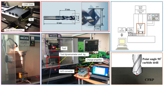
Figure 2.
Schematic of experimental setup for drilling.
The cutting tool used for all drilling tests was an 8 mm diameter carbide drill with a point angle of 90°, a relief angle of 10°, a helix angle of 30° and a total length of 63 mm. The cutting tool and its specifications are displayed in Figure 3. The size of the cutting tool was chosen since it is one of the most common sizes used to produce holes for rivets in aerospace structures. Moreover, the smaller point angle is helpful to reduce thrust force and is more conducive to drilling operation. Singh et al. [35] found that a 90° drill point angle gives better results, as compared to 104° and 118°, in drilling-induced damage while drilling UD-GFRP composite laminates. On the other hand, the spindle speed and feed rate are two of the most important parameters in analyzing drilling quality and are always selected as research objects. Many researchers have pointed out that the burr formation and the hole circularity depend on different cutting parameters [36]. In this study, 300 holes were, respectively, drilled on CFRP and C-AFRP laminates with back support at a feed rate of 200 mm/min and a spindle speed of 2000 rpm. Oil cooling cannot be used in drilling operation because it will lead to the contamination of the FRP materials. Thus, the cooling system was developed by means of a Vortex Tube Magnet Base 2 (Seyang Mechatronics Co., Ltd., Gyeonggi-do, Korea) with a hot component and a cool component. The advantage of this cooling system is that the cold air flow and temperature can easily be controlled to obtain more homogeneous distribution of cooling by adjusting the slotted valve in the hot air outlet.
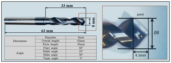
Figure 3.
Cutting tool and drill specifications.
2.3. Thrust Force Analysis and Tool Wear Analysis
The thrust force plays an important role, which is closely connected to the defects and processing quality. It is very important to predict the thrust force at the onset of delamination and to control the thrust force during the drilling process for a reduction in the drilling part damage caused by delamination. Ho-cheng and Dharan [37] used Timoshenko’s classic plate-bending theory to propose a critical thrust model for twist drills for the first time. The critical thrust force model is expressed as [37,38]:
where GIC is the critical crack propagation energy per unit area, dA is the increase in the area of the delamination crack, FA is the thrust force, X is the displacement and dU is the infinitesimal strain energy. The isotropic behavior and pure bending of the laminate are assumed in the model. In Equation (1), one notes that
For a circular plate subject to clamped ends and a concentrated load, the stored strain energy U is
where M is the stiffness per unit width of the fiber-reinforced material given by
E is Young’s modulus and ν is Poisson’s ratio for the material, and the displacement X is
Therefore, the thrust force at the onset of crack propagation can be calculated, where E is the Young’s modulus and h is the thickness of uncut plies beneath the drill.
For tool wear analysis, many instruments and techniques are used to measure and analyze tool wear. The confocal microscope accurately provides the profile information of the worn cutting edges. The use of a scanning electron microscope (SEM) to observe and analyze tool wear is currently one of the simplest and most effective methods. The SEM images were used to provide the high magnification pictures of the wear pattern. In this study, the SEM images for analysis of tool wear was photographed with a non-contact image analyzer (VMS-2515F, Rational Precision Instrument Co., Ltd., Dongguan City, Guangdong Province, China), as shown in Figure 4. The wear volume (per unit length) was measured using the confocal images by subtracting the original 2D profile of the tool from the worn 2D profile of the tool and subsequently multiplying a unit length.
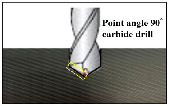
Figure 4.
Tool wear position in drilling operation.
2.4. Tensile Test
The dimensions of the specimens and the experimental methods of the tensile test were based on the ASTM D3039 standard test methods for tensile properties of polymer matrix composite materials. As shown in Figure 5, the tensile test was carried out on an electric motor-type Universal Testing Machine (UTM, AG-100 kNX plus, Tokyo, Japan) with a constant head speed of 2 mm/min. To measure the strain, an extensometer was attached to the sample, and the tensile strength and strain data were stored through a data acquisition system connected to the tester. The tensile test was performed three times for each sample, and the average value was defined as the final tensile strength and strain.
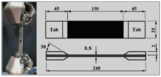
Figure 5.
Tensile test and tensile specimen.
3. Results and Discussion
3.1. Tensile Behaviors and Properties
Figure 6 shows the tensile test results of CFRP and C-AFRP. The results of the tensile tests from the CFRP and C-AFRP are summarized in Table 2. From Figure 6 and Table 2, it is observed that the C-AFRP hybrid composite has higher tensile strength, higher tensile modulus and smaller tensile failure elongation compared to those of CFRP. The average ultimate tensile strength of CFRP and C-AFRP hybrid composite were 431.20 and 734.75 MPa, respectively. The average tensile moduli of CFRP and C-AFRP hybrid composites were 21.69 and 55.68 GPa, respectively. Additionally, the strains at the breaks of the CFRP and C-AFRP hybrid composites were approximately 2.13% and 2.13%, respectively. The tension strength and tensile modulus of C-AFRP were, respectively, increased by 70.40% and 1.57%, compared with that of CFRP. This may be attributed to the synergistic effect (interaction between fiber layers) of carbon fibers and aramid fibers under the action of the external force of the C-AFRP hybrid composite. A similar phenomenon was also observed by Zhang et al. [39]. The material has higher tensile strength and smaller strain, which can promote this material to maintain a smaller strain when subjected to a larger tensile force. Therefore, the use of hybrid composites can improve the mechanical properties of pure CFRP, to some extent. Similar conclusions were also drawn by Naresh et al. [40].
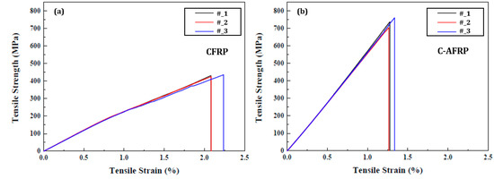
Figure 6.
Stress–strain curves of (a) CFRP and (b) C-AFRP.
Table 2.
Tensile test results.
3.2. Burr Formation
The carbon fiber composites drilling is prone to produce many unique features, such as cracks, uncut fibers, fiber pull-out and delamination. Additionally, these uncut fibers are called burr. In general, burr often formed on the exit surface of drilled holes after the drilling process. The burr shape is irregular, and it cannot be removed easily using a punching process, due to the withdrawal in the feed direction of a drill bit [41,42]. Jeong et al. [43] reported that the burr cannot be completely removed in the drilling process, even through the repeated optimization of drilling parameter, it can reduce the burr formation. Although the burr formed during the drilling process usually does not have a negative impact on the mechanical properties of the carbon fiber composite parts, the complete removal of them requires some additional machining operations, resulting in an increase in processing costs. In this study, CFRP and C-AFRP were drilled using an 8 mm diameter carbide drill with a point angle of 90°, while the spindle speed and feed rate were 2000 rpm and 200 mm/min, respectively. The burr is generated on the exit side of the hole in the drilling of CFRP and C-AFRP, as shown in Figure 7. It can be clearly observed in Figure 7 that more burrs are generated by drilling C-AFRP than that of drilling CFRP, and the clear yield and necking phenomena of aramid fibers are also observed. In addition, on the whole, more or larger burrs are formed as the number of drilling holes increases. The reason may be attributed to the bending-dominated failure mode governing the chip separation in this circumference region, and the high-fiber recession to cutting edges in the laminate bottom. Both of these coupled effects on carbon and aramid fibers drilling lead to the evidence that many irregular-fractured fibers are generated [44]. Moreover, other researchers also found that large burr defects are formatted by the tensile force during the cutting process, and few burr defects are found when the fiber is in a shear stress state. Ji et al. [45] reported that the angle between the cutting direction and the fiber orientation plays an important role in burr formation—the vibration of workpiece and the rise of outlet temperature are the other reasons—and, secondly, the vibration of the workpiece and the increase in the outlet temperature are another reason.
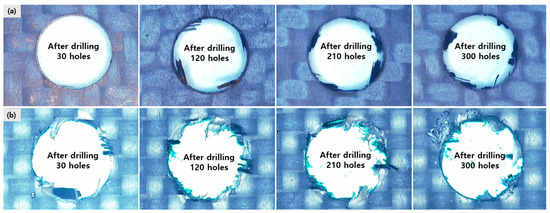
Figure 7.
Burr formation in drilling of (a) CFRP and (b) C-AFRP.
3.3. Thrust Force
Since the thrust force directly affects the quality of the machined hole in the drilling of polymer composite materials, it is essential to study the generation and mechanism of thrust force. This is because the thrust force plays a key role in determining the degree of delamination damage [44,46]. Delamination occurs when the thrust exceeds the interlayer bond strength of the laminate under the continuous cutting motion at the hole exit. Therefore, in order to restrain the delamination damage, it has great significance to predict the thrust force at the beginning of the delamination and to control the thrust force during the drilling process. The total thrust force is divided into three components in the drilling of polymer composite materials: (i) thrust force generated by the cutting lips; (ii) thrust force generated by the chisel edge cutting action; (iii) extrusion force generated by the chisel edge extrusion action [47]. Figure 8 illustrates the effects of the number of holes drilled on the thrust force. A total of 300 holes was, respectively, drilled on CFRP and C-AFRP, using an 8 mm diameter carbide drill with a point angle of 90°, a 2000 rpm spindle speed and a 200 mm/min feed rate. As shown in Figure 8, it can be clearly seen that the thrust force produced by drilling CFRP is obviously higher than that of drilling C-AFRP. The average thrust force is 321.76 N for CFRP and 78.51 N for C-AFRP. This shows that different composite materials have a strong influence on the thrust force. In the process of drilling composite materials, the mechanical strength of the composite material in the feed direction depends on the mechanical strength of the resin. On the other hand, as shown in Figure 8, the thrust seems to increase with the number of holes, which is consistent with other research results [48]. This may mainly contribute to tool wear, which increases with the number of holes drilled. In addition, the thrust force is also related to the geometry of the tool, feed rate, spindle speed, and other factors. Therefore, selecting a suitable bit, such as twist drill, properly reducing the feed rate and increasing the spindle speed, is conducive to reducing the thrust force. In particular, the high cutting temperature caused by high-speed drilling softens the epoxy matrix and reduces the thrust force, which is beneficial to the drilling of the polymer composite materials [44].
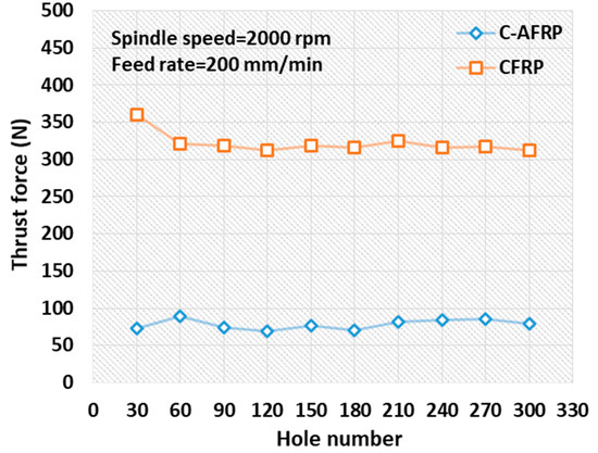
Figure 8.
Burr formation in drilling of CFRP and C-AFRP.
3.4. Tool Wear
Drill wear is a serious problem in the drilling of holes, as it is necessary to prevent the damage of cutting tools and workpieces. The non-homogenous and anisotropic properties of fiber composite materials lead to a high wear effect on the cutting tool, resulting in the difficult drilling of these materials and delamination damage [42]. Therefore, it has great significance for the study of tool wear to evaluate tool life, durability, cutting performance, etc. In general, tool wear shows the tribological properties and physical characteristics at the tool–work interfaces in the real cutting process. For tool wear analysis, a total of 300 holes was, respectively, drilled on CFRP and C-AFRP using an 8 mm diameter carbide drill with a point angle of 90°, a 2000 rpm spindle speed and a 200 mm/min feed rate. Figure 9 displays SEM images of the carbide drill after drilling 30 and 300 holes for CFRP and C-AFRP. As shown in Figure 9, the tool wear mainly occurs on the flank side, so this kind of wear is also called flank wear. This typically wear leads to a rapid dulling of the cutting edges. After drilling 300 holes, some edge chipping and severe flank wear (see illustrations) were found on the cutting lip and the flank face, respectively. Moreover, it can be clearly observed that the tool wear caused by drilling CFRP is significantly more serious than drilling C-AFRP in Figure 9. This may be related to the high wear-resistance properties of CFRP [49]. The existence of hard carbon fibers in CFRP leads to excessive tool wear. Generally, the mechanism of tool wear in drilling of composite laminates can be attributed to abrasive wear, adhesion and chipping. This abrasive wear is also called mechanical wear. As the main tool wear factor in drilling of composite laminates, it is mainly caused by the strong wear resistance of carbon fibers [50]. The specific tool wear in the drilling of CFRP and C-AFRP, according to hole number, is shown in Figure 10. The flank wear of the carbide drill began after 30 holes with the slightly faster progress up to 90 holes, and then the wear progress becomes slightly steadier from 120 holes until 300 holes. In the initial stage of drilling, because the surface roughness of the carbide drill is high in the early coupling stage, their actual contact area suffers high pressure and severe friction, resulting in faster tool wear in the initial stage. Then, after drilling nearly 90 holes, the carbide drill passes the rapid wear stage and reaches the normal wear stage, which indicates that the tool-working friction pair that controls the chip removal process is in a stable state. Similar conclusions were also reported by [44]. Xu et al. [44] also proposed to evaluate the failure degree of tool wear—that is, the average flank wear land width greater than 0.25 mm is failure. However, the average flank wear land width in this experiment is much lower than 0.25mm—that is, the tool has not failed.
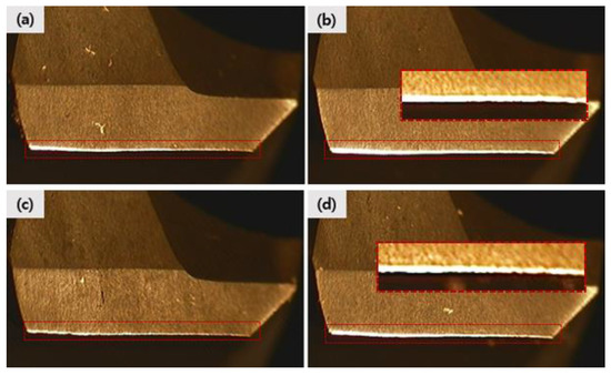
Figure 9.
SEM images of carbide drill after drilling 30 and 300 holes for CFRP (a,b) and C-AFRP (c,d).
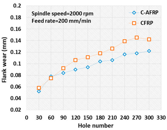
Figure 10.
Tool wear in drilling of CFRP and C-AFRP according to hole number.
4. Conclusions
In this paper, the drilling characteristics of carbon fiber-reinforced polymer (CFRP) and aramid fiber-reinforced polymer (AFRP) hybrid composites (C-AFRP) have been experimentally investigated. This work investigated the impact of a number of consecutive holes drilled on burr formation and tool wear in the drilling of CFRP and C-AFRP composites by using an 8 mm diameter carbide drill with a point angle of 90°, a relief angle of 10°, a helix angle of 30° and a total length of 63 mm. The following conclusions can be drawn:
- The C-AFRP hybrid composites were successfully synthesized for the first time, and their drilling characteristics, including burr formation and tool wear, were investigated, compared with CFRP.
- The tensile properties of the CFRP were improved with the mixing of carbon and aramid fibers. The average ultimate tensile strength of C-AFRP hybrid composites was increased by about 70%, compared to CFRP.
- The thrust force and tool wear caused by drilling C-AFRP hybrid composites were significantly less than those by drilling CFRP. However, the only disadvantage is that drilling C-AFRP composites produced more burrs than drilling CFRP. Therefore, it is necessary to focus on reducing burr formation during the drilling of C-AFRP hybrid composites in the future.
Author Contributions
Conceptualization, J.H.L.; methodology, J.H.L.; validation, J.H.S.; formal analysis, J.H.L.; investigation, J.H.L., J.C.G. and J.H.S.; resources, J.H.L.; data curation, J.H.L., J.C.G. and J.H.S.; writing—original draft preparation, J.H.L.; writing—review and editing, J.H.L., J.C.G. and J.H.S.; funding acquisition, J.H.L. All authors have read and agreed to the published version of the manuscript.
Funding
This research was supported by Basic Science Research Program through the National Research Foundation of Korea (NRF), funded by the Ministry of Education (2019R1I1A1A01043653). This research was supported by “Research Base Construction Fund Support Program”, funded by Jeonbuk National University in 2018.
Institutional Review Board Statement
Not applicable.
Informed Consent Statement
Not applicable.
Data Availability Statement
The data presented in this study are available on request from the first author and corresponding authors.
Conflicts of Interest
The authors declare no conflict of interest.
References
- Mazumdar, S. Composites Manufacturing: Materials, Product, and Process Engineering; CRC Press: Boca Raton, FL, USA, 2001. [Google Scholar]
- Bunsell, A.R.; Renard, J. Fundamentals of Fibre Reinforced Composite Materials; CRC Press: Boca Raton, FL, USA, 2005. [Google Scholar]
- Mohan, N.; Ramachandra, A.; Kulkarni, S. Influence of Process Parameters on Cutting Force and Torque during Drilling of Glass-Fiber Polyester Reinforced Composites. Compos. Struct. 2005, 71, 407–413. [Google Scholar] [CrossRef]
- Mitchell, B.S. An Introduction to Materials Engineering and Science for Chemical and Materials Engineers; John Wiley & Sons: Hoboken, NJ, USA, 2004. [Google Scholar]
- Karataş, M.A.; Gökkaya, H. A Review on Machinability of Carbon Fiber Reinforced Polymer (CFRP) and Glass Fiber Reinforced Polymer (GFRP) Composite Materials. Def. Technol. 2018, 14, 318–326. [Google Scholar] [CrossRef]
- Erden, S.; Ho, K. Fiber Reinforced Composites. In Fiber Technology for Fiber-Reinforced Composites; Elsevier: Amsterdam, The Netherlands, 2017; pp. 51–79. [Google Scholar]
- Mallick, P.K. Fiber-Reinforced Composites: Materials, Manufacturing, and Design; CRC Press: Boca Raton, FL, USA, 2007. [Google Scholar]
- Geng, D.; Liu, Y.; Shao, Z.; Lu, Z.; Cai, J.; Li, X.; Jiang, X.; Zhang, D. Delamination Formation, Evaluation and Suppression during Drilling of Composite Laminates: A Review. Compos. Struct. 2019, 216, 168–186. [Google Scholar] [CrossRef]
- Anarghya, A.; Harshith, D.; Rao, N.; Nayak, N.S.; Gurumurthy, B.; Abhishek, V.; Patil, I.G.S. Thrust and Torque Force Analysis in the Drilling of Aramid Fibre-Reinforced Composite Laminates Using RSM and MLPNN-GA. Heliyon 2018, 4, e00703. [Google Scholar] [CrossRef]
- Liu, S.; Yang, T.; Liu, C.; Jin, Y.; Sun, D.; Shen, Y. Modelling and Experimental Validation on Drilling Delamination of Aramid Fiber Reinforced Plastic Composites. Compos. Struct. 2020, 236, 111907. [Google Scholar] [CrossRef]
- Wang, C.; Liu, G.; An, Q.; Chen, M. Occurrence and Formation Mechanism of Surface Cavity Defects during Orthogonal Milling of CFRP Laminates. Compos. Part B Eng. 2017, 109, 10–22. [Google Scholar] [CrossRef]
- Voß, R.; Henerichs, M.; Rupp, S.; Kuster, F.; Wegener, K. Evaluation of Bore Exit Quality for Fibre Reinforced Plastics Including Delamination and Uncut Fibres. CIRP J. Manuf. Sci. Technol. 2016, 12, 56–66. [Google Scholar] [CrossRef]
- Li, N.; Li, Y.; Zhou, J.; He, Y.; Hao, X. Drilling Delamination and Thermal Damage of Carbon Nanotube/Carbon Fiber Reinforced Epoxy Composites Processed by Microwave Curing. Int. J. Mach. Tools Manuf. 2015, 97, 11–17. [Google Scholar] [CrossRef]
- Saoudi, J.; Zitoune, R.; Gururaja, S.; Mezlini, S.; Hajjaji, A.A. Prediction of Critical Thrust Force for Exit-Ply Delamination during Drilling Composite Laminates: Thermo-Mechanical Analysis. Int. J. Mach. Mach. Mater. 2016, 18, 77–98. [Google Scholar] [CrossRef]
- Vigneshwaran, S.; Uthayakumar, M.; Arumugaprabu, V. Review on Machinability of Fiber Reinforced Polymers: A Drilling Approach. Silicon 2018, 10, 2295–2305. [Google Scholar] [CrossRef]
- Abrão, A.M.; Faria, P.E.; Rubio, J.C.; Reis, P.; Davim, J.P. Drilling of Fiber Reinforced Plastics: A Review. J. Mater. Process. Technol. 2007, 186, 1–7. [Google Scholar] [CrossRef]
- Panchagnula, K.K.; Palaniyandi, K. Drilling on Fiber Reinforced Polymer/Nanopolymer Composite Laminates: A Review. J. Mater. Res. Technol. 2018, 7, 180–189. [Google Scholar] [CrossRef]
- Cadorin, N.; Zitoune, R.; Seitier, P.; Collombet, F. Analysis of Damage Mechanism and Tool Wear While Drilling of 3D Woven Composite Materials Using Internal and External Cutting Fluid. J. Compos. Mater. 2015, 49, 2687–2703. [Google Scholar] [CrossRef]
- Cadorin, N.; Zitoune, R. Wear Signature on Hole Defects as a Function of Cutting Tool Material for Drilling 3D Interlock Composite. Wear 2015, 332, 742–751. [Google Scholar] [CrossRef]
- Zitoune, R.; Cadorin, N.; Collombet, F.; Šíma, M. Temperature and Wear Analysis in Function of the Cutting Tool Coating When Drilling of Composite Structure: In Situ Measurement by Optical Fiber. Wear 2017, 376, 1849–1858. [Google Scholar] [CrossRef]
- Saoudi, J.; Zitoune, R.; Gururaja, S.; Salem, M.; Mezleni, S. Analytical and Experimental Investigation of the Delamination during Drilling of Composite Structures with Core Drill Made of Diamond Grits: X-ray Tomography Analysis. J. Compos. Mater. 2018, 52, 1281–1294. [Google Scholar] [CrossRef]
- Kumar, D.; Singh, K.K.; Zitoune, R. Impact of the Carbon Nanotube Reinforcement in Glass/Epoxy Polymeric Nanocomposite on the Quality of Fiber Laser Drilling. Proc. Inst. Mech. Eng. Part B J. Eng. Manuf. 2018, 232, 2533–2546. [Google Scholar] [CrossRef]
- Zheng, L.; Zhou, H.; Gao, C.; Yuan, J. Hole Drilling in Ceramics/Kevlar Fiber Reinforced Plastics Double-Plate Composite Armor Using Diamond Core Drill. Mater. Des. 2012, 40, 461–466. [Google Scholar] [CrossRef]
- Hirogaki, T.; Aoyama, E.; Inoue, H.; Ogawa, K.; Maeda, S.; Katayama, T. Laser Drilling of Blind via Holes in Aramid and Glass/Epoxy Composites for Multi-Layer Printed Wiring Boards. Compos. Part A Appl. Sci. Manuf. 2001, 32, 963–968. [Google Scholar] [CrossRef]
- Karpat, Y.; Değer, B.; Bahtiyar, O. Drilling Thick Fabric Woven CFRP Laminates with Double Point Angle Drills. J. Mater. Process. Technol. 2012, 212, 2117–2127. [Google Scholar] [CrossRef]
- Murphy, C.; Byrne, G.; Gilchrist, M. The Performance of Coated Tungsten Carbide Drills when Machining Carbon Fibre-Reinforced Epoxy Composite Materials. Proc. Inst. Mech. Eng. Part B J. Eng. Manuf. 2002, 216, 143–152. [Google Scholar] [CrossRef]
- Durão, L.M.P.; Gonçalves, D.J.S.; Tavares, J.M.R.S.; de Albuquerque, V.H.C.; Aguiar Vieira, A.; Torres Marques, A. Drilling Tool Geometry Evaluation for Reinforced Composite Laminates. Compos. Struct. 2010, 92, 1545–1550. [Google Scholar] [CrossRef]
- Davim, J.P.; Reis, P. Drilling Carbon Fiber Reinforced Plastics Manufactured by Autoclave—Experimental and Statistical Study. Mater. Des. 2003, 24, 315–324. [Google Scholar] [CrossRef]
- Jia, Z.; Fu, R.; Niu, B.; Qian, B.; Bai, Y.; Wang, F. Novel Drill Structure for Damage Reduction in Drilling CFRP Composites. Int. J. Mach. Tools Manuf. 2016, 110, 55–65. [Google Scholar] [CrossRef]
- Babu, P.R.; Pradhan, B. Effect of Damage Levels and Curing Stresses on Delamination Growth Behaviour Emanating from Circular Holes in Laminated FRP Composites. Compos. Part A Appl. Sci. Manuf. 2007, 38, 2412–2421. [Google Scholar] [CrossRef]
- Davim, J.P.; Reis, P. Study of Delamination in Drilling Carbon Fiber Reinforced Plastics (CFRP) Using Design Experiments. Compos. Struct. 2003, 59, 481–487. [Google Scholar] [CrossRef]
- Geng, D.; Liu, Y.; Shao, Z.; Zhang, M.; Jiang, X.; Zhang, D. Delamination Formation and Suppression during Rotary Ultrasonic Elliptical Machining of CFRP. Compos. Part B Eng. 2020, 183, 107698. [Google Scholar] [CrossRef]
- Tanaka, K.; Yamada, M.; Kohashi, N.; Katayama, T. High-Speed Compression Moulding of CFRTP/AFRTP Hybrid Composites Using an Electromagnetic Induction Heating System. High Perform. Struct. Mater. V 2010, 112, 141–151. [Google Scholar]
- Cheon, J.; Lee, M.; Kim, M. Study on the Stab Resistance Mechanism and Performance of the Carbon, Glass and Aramid Fiber Reinforced Polymer and Hybrid Composites. Compos. Struct. 2020, 234, 111690. [Google Scholar] [CrossRef]
- Singh, I.; Bhatnagar, N.; Viswanath, P. Drilling of Uni-directional Glass Fiber Reinforced Plastics: Experimental and Finite Element Study. Mater. Des. 2008, 29, 546–553. [Google Scholar] [CrossRef]
- Giasin, K.; Ayvar-Soberanis, S.; Hodzic, A. The Effects of Minimum Quantity Lubrication and Cryogenic Liquid Nitrogen Cooling on Drilled Hole Quality in GLARE Fibre Metal Laminates. Mater. Des. 2016, 89, 996–1006. [Google Scholar] [CrossRef]
- Ho-Cheng, H.; Dharan, C. Delamination during Drilling in Composite Laminates. J. Eng. Ind. 1990, 112, 236–239. [Google Scholar] [CrossRef]
- Hocheng, H.; Tsao, C. The Path Towards Delamination-Free Drilling of Composite Materials. J. Mater. Process. Technol. 2005, 167, 251–264. [Google Scholar] [CrossRef]
- Zhang, Y.; Li, Y.; Ma, H.; Yu, T. Tensile and Interfacial Properties of Unidirectional Flax/Glass Fiber Reinforced Hybrid Composites. Compos. Sci. Technol. 2013, 88, 172–177. [Google Scholar] [CrossRef]
- Naresh, K.; Shankar, K.; Velmurugan, R.; Gupta, N. Statistical Analysis of the Tensile Strength of GFRP, CFRP and Hybrid Composites. Thin Walled Struct. 2018, 126, 150–161. [Google Scholar] [CrossRef]
- Kurniawan, R.; Thirumalai Kumaran, S.; Arumuga Prabu, V.; Zhen, Y.; Park, K.M.; Kwak, Y.I.; Mofizul Islam, M.; Ko, T.J. Measurement of Burr Removal Rate and Analysis of Machining Parameters in Ultrasonic Assisted Dry EDM (US-EDM) for Deburring Drilled Holes in CFRP Composite. Measurement 2017, 110, 98–115. [Google Scholar] [CrossRef]
- Geier, N.; Davim, J.P.; Szalay, T. Advanced Cutting Tools and Technologies for Drilling Carbon Fibre Reinforced Polymer (CFRP) Composites: A Review. Compos. Part A Appl. Sci. Manuf. 2019, 125, 105552. [Google Scholar] [CrossRef]
- Jeong, Y.H.; HanYoo, B.; Lee, H.U.; Min, B.-K.; Cho, D.-W.; Lee, S.J. Deburring Microfeatures Using Micro-EDM. J. Mater. Process. Technol. 2009, 209, 5399–5406. [Google Scholar] [CrossRef]
- Xu, J.; An, Q.; Chen, M. A Comparative Evaluation of Polycrystalline Diamond Drills in Drilling high-Strength T800S/250F CFRP. Compos. Struct. 2014, 117, 71–82. [Google Scholar] [CrossRef]
- Ji, W.; Wang, Y.W.; Li, Y.; Yan, F.; Liu, X. Study of Exit Burr Formation of CFRP. Adv. Mater. Res. 2011, 188, 154–157. [Google Scholar] [CrossRef]
- Singh, A.P.; Sharma, M.; Singh, I. A Review of Modeling and Control during Drilling of Fiber Reinforced Plastic Composites. Compos. Part B Eng. 2013, 47, 118–125. [Google Scholar] [CrossRef]
- Liu, S.; Yang, T.; Liu, C.; Jin, Y.; Sun, D.; Shen, Y. Mechanistic Force Modelling in Drilling of AFRP Composite Considering the Chisel Edge Extrusion. Int. J. Adv. Manuf. Technol. 2020, 109, 33–44. [Google Scholar] [CrossRef]
- Basmaci, G.; Yoruk, A.S.; Koklu, U.; Morkavuk, S. Impact of Cryogenic Condition and Drill Diameter on Drilling Performance of CFRP. Appl. Sci. 2017, 7, 667. [Google Scholar] [CrossRef]
- Park, K.-H.; Beal, A.; Kim, D.; Kwon, P.; Lantrip, J. Tool Wear in Drilling of Composite/Titanium Stacks Using Carbide and Polycrystalline Diamond Tools. Wear 2011, 271, 2826–2835. [Google Scholar] [CrossRef]
- Liu, D.; Tang, Y.; Cong, W. A Review of Mechanical Drilling for Composite Laminates. Compos. Struct. 2012, 94, 1265–1279. [Google Scholar] [CrossRef]
Publisher’s Note: MDPI stays neutral with regard to jurisdictional claims in published maps and institutional affiliations. |
© 2021 by the authors. Licensee MDPI, Basel, Switzerland. This article is an open access article distributed under the terms and conditions of the Creative Commons Attribution (CC BY) license (http://creativecommons.org/licenses/by/4.0/).