Article

Evaluation of Siltation Degree of Permeable Asphalt Pavement and Detection of Noise Reduction Degree

1
College of Construction Engineering, Jilin University, Changchun 130026, China
2
College of Transportation, Changchun Institute of Architecture, Changchun 130604, China
*
Author to whom correspondence should be addressed.
Appl. Sci. 2021, 11(1), 349; https://doi.org/10.3390/app11010349
Submission received: 3 December 2020 / Revised: 28 December 2020 / Accepted: 29 December 2020 / Published: 31 December 2020

Abstract

:

Featured Application

This study proposes a method for evaluating the siltation of permeable pavement, and it is concluded that the road noise is proportional to the degree of siltation of permeable pavement.

Abstract

This study mainly uses PFC (particle follow code) to simulate the void characteristics of permeable asphalt mixture, and uses these to simulate the silting process. Then, a tire drop test was used to evaluate the noise reduction performance of permeable asphalt concrete. Finally, a self-made ring rutting test machine was used to simulate the silting process. Through experiments, the following conclusions were obtained: 1. The critical size of the sludge particle size is 0.3 mm–0.6 mm. 2. The quality of the water-permeable asphalt concrete specimens increased by 13% before and after silting, and the porosity of the specimens finally decreased from about 20% to about 8%. The water-permeable function only retained less than 20% of the original, and the water-permeable function was basically lost. 3. By measuring the road noise detection, it was found that the road noise is directly proportional to the degree of blockage of the permeable road. Compared with the original road with a perfect permeable function, the road noise of the completely blocked road increased by about 4 decibels. This study reveals the silting process of permeable asphalt mixture and the key particle size of the silt, which is of great significance for the detection, cleaning and maintenance of permeable asphalt pavements.

1. Introduction

Permeable pavements can effectively reduce water accumulation on urban roads. Permeable pavements, obtained by means of porous asphalt concrete (PAC), have attracted increasing attention due to the benefits that they provide, such as reduced traffic noise, good visibility and a better pavement skid resistance on rainy days, which is achieved by the drainage capability of this type of mix and by the macro-texture that appears due to the aggregate gradation of the mixtures [1,2,3]. A permeable pavement with good water permeability can reach a penetration rate of over 130 mm/h [4,5,6,7,8,9,10,11,12,13]. The permeable structure is a “skeleton-pore” structure formed by interlocking coarse aggregates [14,15,16,17]. The clogging behavior is characterized by an increase in the quantity of sediments and particulate matter retained on the pavement surface [18]. Zhao and Yang [19] studied the influence of seepage velocity and plugging particle size on the seepage of asphalt mixtures. It was verified that there is a correlation between the asphalt mixture seepage velocity and open pores.
The problem of blockage is a very important part of the study of permeable roads. Solving the blockage of permeable pavements will make an important contribution to the promotion of permeable pavements. Elvik [20] et al. analyzed the impact of the quality of permeable asphalt pavement plugging materials on the clogging performance, and concluded that as the service life of a permeable asphalt pavement gradually increases, the water permeability will decrease. Coarse sand particles did not significantly reduce permeability as these large particles did not enter surface pores [21,22]. Nguyen et al. found that silty clay and sand caused the most rapid clogging [23]. Chopra et al. [24] analyzed the silting problem of the permeable pavement in the use stage, and analyzed the particle size distribution of the blockage, and found that almost all sand particles were clay-like, and then proposed a solution to design a double-layer permeable asphalt pavement. Guan [25] analyzed the water permeability mechanism. The silting behavior of a permeable pavement was simulated and analyzed, and the infiltration model of a permeable asphalt pavement is proposed. Sun [26] further improved and analyzed the water permeability measurement device, and a simulated rainfall system was developed to explore the blocking behavior pattern. Kang and Xu [27] designed and prepared a constant head permeability test device, improving the epoxy resin sealing on the side of the test piece. By measuring the change of permeability coefficient of permeable asphalt mixture under the action of rain, the clogging effect is analyzed.
Permeability is an important performance characteristic of permeable asphalt pavements, which can be determined by permeability tests. The testing method of porosity and the permeability coefficient of permeable asphalt pavements has always been the research focus of foreign experts. Montes et al. [28] conducted a variable head penetration test and defined the head difference loss per unit time as the permeability coefficient to evaluate the water permeability of the permeable pavement. Alalea Kia et al. [29] studied the measurement of the permeability coefficient. The permeability coefficient was measured by the on-site variable head permeability test and calculated based on the time required for the water flow to drop to the specified penetration depth.
Kamiya K [30] et al. studied the permeable pavement of the large-gap expressway that has been in use all the year round. They believe that in the maintenance and repair of the permeable pavement plan, in order to determine the magnitude of the road hazard coefficient, a non-destructive testing method needs to be found. Balades et al. [31] verified the maintenance effect of high-pressure washing on a permeable pavement.
In this paper, the void characteristics of the permeable asphalt mixture are obtained through discrete element simulation. Based on the characteristics of the porosity, the silting process is simulated in detail to observe the silting situation. The microscopic effects of the number of siltations, particle size, void shape, and water flow on the siltation situation are explored, and the various siltation processes, their characteristics, and the location of the siltation are analyzed and summarized. Through the indoor Marshall specimen silting simulation test, the changes in the weight, porosity and water permeability of the asphalt mixture during the silting process are explored, and the changes in the permeability of the asphalt mixture during the silting process are evaluated from multiple angles to prepare for the subsequent silting detection. According to the relationship between the noise level before and after the permeable pavement is blocked, an efficient and non-destructive detection method is proposed, which can quantitatively evaluate the degree of congestion of the permeable pavement.

2. Materials and Equipment

2.1. Experimental Materials

2.1.1. Stone

As we all know, the permeable asphalt mixture has less fine aggregate and larger pores, resulting in fewer contact points between stones than dense mixtures. Therefore, in order to ensure the necessary strength of the road surface when the aggregate point contact surface is small it is necessary for the stone to use hard aggregate. The aggregate used in this test is alkaline limestone produced by Jiutai Hongda Stone Factory. The surface of the stone is clean, wear-resistant, multi-angular and anti-breaking. According to the Chinese Test Methods of Aggregates for Highway Engineering (JTG E42-2005), Table 1 summarizes the limestone and coarse bone technical parameters of Jiutai Hongda Stone Factory.

2.1.2. Asphalt

Due to the large pore structure of the permeable asphalt pavement, the strength will be affected for a period of time after being put to use due to water damage, road damage and for other reasons. Therefore, the asphalt must have a higher viscosity. SBS (Styrene-Butadiene-Styrene) is a styrene thermoplastic elastomer and is a styrene-butadiene-styrene triblock copolymer. As construction materials, high-viscosity SBS modified asphalt is generally used. The performance indexes of SBS modified asphalt are obtained according to Standard Test Methods of Bitumen and Bituminous Mixtures for Highway Engineering (JTG E20-2011) standard. The asphalt used in this test is SBS-modified asphalt produced by Shandong Zibo Qi Cultural Industry Co., Ltd. Its various indicators are shown in Table 2.

2.1.3. Blockage

In order to study the chemical composition, particle size composition and other properties of the silt, this experiment collected road surface silt from Renmin Street in Changchun City. The collected sludge sample is shown in Figure 1. In order to study the composition of sludge, after drying the collected samples, we took a small part of the samples for an XRF(X-Ray Fluorescence) test. At the beginning of the test, X-rays were emitted to the sample under test by using the excitation source of the XRF instrument. The different elements contained in the excited sample emit secondary X-rays with specific energy and specific wavelength. The intensity of the radiation varies with the concentration of the elements contained in the sample. The software converts the characteristic quantity information detected by the detection system into the type and content of each element in the sample. XRF testing has a wide range of applications, and can detect elements 9 (F) to 92 (U). The type of chemical element contained in the silt and the mass ratio of each element can be obtained through the XRF test.
Using XRF test to detect road blockages, the chemical elements in the blockages and the quality of each element are shown in Table 3.
Through the analysis of the sources of various elements in the silt, it is concluded that heavy metal ions such as Pb and Zn come from automobile exhaust pollutants, fuel or lubricating oil leaked during driving, and deicing agents. Petroleum pitch contains C, H, S, N and some metal elements. Tires are generally made of rubber, and their wear contains elements such as C, H, S, Zn, and SiO2 comes from stones and tire reinforcement.
It can be seen from the content of each element in the table that the road surface blockage mainly comes from the abrasion of the road material. There is also a small part of it coming from tire wear and other road deposits generated during driving, heavy metal ions in rainwater, pollutants leaked from driving, snow removal agents, etc.
The experiment of simulating the process of pavement siltation needs to prepare a certain grade of stone to simulate the blocking agent. Therefore, the collected road surface silt is screened with a geosieve to obtain the mass proportion of each particle size of the silt in the actual road surface, as shown in Table 4.

2.2. Experimental Equipment

2.2.1. Moving Water Scourer

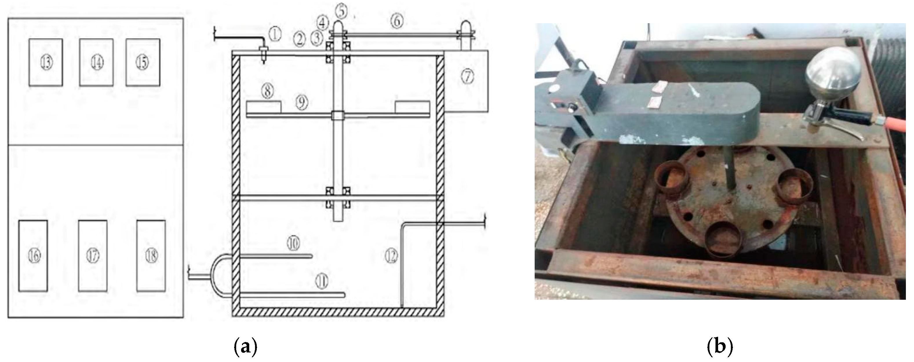
In order to complete the simulated rainfall, a dynamic water scour instrument was used to simulate the silting process. The dynamic water scour instrument is mainly composed of several parts: a circulating water tank, a water gun with controllable water pressure, and a rotational base. The circulating water tank and water gun can provide a continuously variable water flow to simulate rainfall. The rotating base ensures that the specimen is evenly exposed to rain. During the test, a thin layer of plastic cloth was laid on the circular base to collect the particles that were not blocked in the test piece. The device structure of the moving water scour instrument is shown in Figure 2.
In the picture: ① water gun; ② support plate; ③ bearing; ④ belt pulley; ⑤ disc fixed shaft; ⑥ belt; ⑦ motor; ⑧ Marshall test piece fixing ring; ⑨ disc; ⑩ temperature sensor; ⑪ U-shaped heating tube; ⑫ water pump Inlet pipe; ⑬ water temperature control meter; ⑭ scouring force control panel; ⑮ disc speed control dial; ⑯⑰⑱ water pump and other auxiliary equipment.

2.2.2. Noise Measuring Instrument—Online Digital Noise Meter

The instrument used to measure the noise level in this experiment was an industrial-grade AR844 handheld online digital noise meter. This noise meter can be used for noise engineering, quality monitoring, health control and various environmental volume measurements. The products complied with: a. International Electrotechnical Commission standards: IEC PUB 651 TYPE2 b. American National Standards: ANSI S1.4TYPE2. The technical parameters of the noise meter are shown in Table 5.
The measuring speed of the noise meter has two gears for selection: fast and slow. The noise meter can lock the maximum value during the measurement process, and directly record 4700 noise data, and can also be connected to a computer to realize the functions of downloading data, collecting data in real time, and analyzing data.

2.2.3. New Type Rutting Test Machine

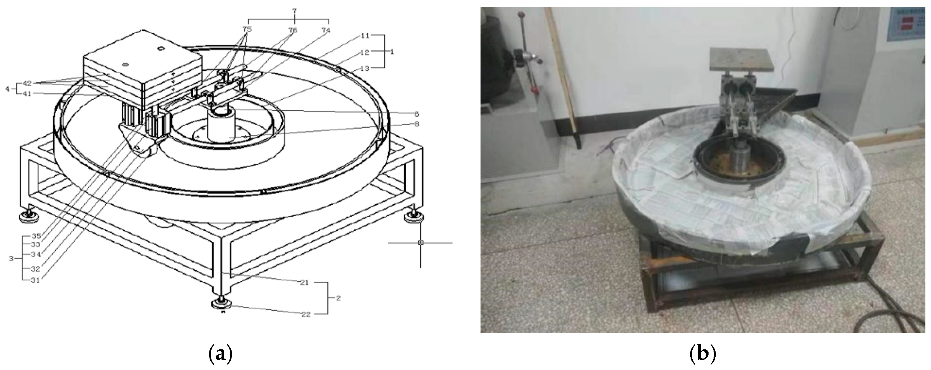
The tire falling method and the improved indoor simulation method use a new rutting test machine developed by Professor Guo Xuedong’s research group. This testing machine integrates the formation of the test piece and the rutting test, which can better simulate actual road conditions. In this test, it can not only be used to form a ring-shaped simulated road, but also the tires with adjustable speed and tire pressure can be used to replace the role of the drum and simulate the actual driving process. The operation is simple and can save on test costs. The new rutting test machine is shown in Figure 3.

2.3. Asphalt Mixture Preparation

For the Marshall sample used in the experiment, according to the Technical Specification for Permeable Asphalt Pavement (CJJ/T 190-2012), the PAC-13 grade was finally selected, and the target porosity was 20%. The oil-stone ratio refers to the weight percentage of the asphalt and minerals in the mixture, and the oil–stone ratio selected in this experiment was 4.8%. The gradation is shown in Table 6. The mass ratio of silt to water was 1:50.

3. Experimental Method

3.1. Characteristics of Blocked Voids in Permeable Asphalt Pavement

PFC (particle follow code) is the basis of the particle flow program. It is mainly used to analyze the stability and deformation of particles, especially in the study of large deformation problems in solid mechanics. The particle model that comes with PFC is only spherical and cannot simulate the real stone shape. In order to get closer to the actual situation of the irregular shape of each particle size aggregate in the mixture, the typical particle shape is first screened, and then several irregular particle models are drawn through CAD (Computer Aided Design) software and imported into the PFC software. The PFC software is used to generate a particle template that meets the requirements, and then calls on the particle template to randomly generate a specified number of particles to simulate the Marshall model. Figure 4 shows the resulting particle mode.
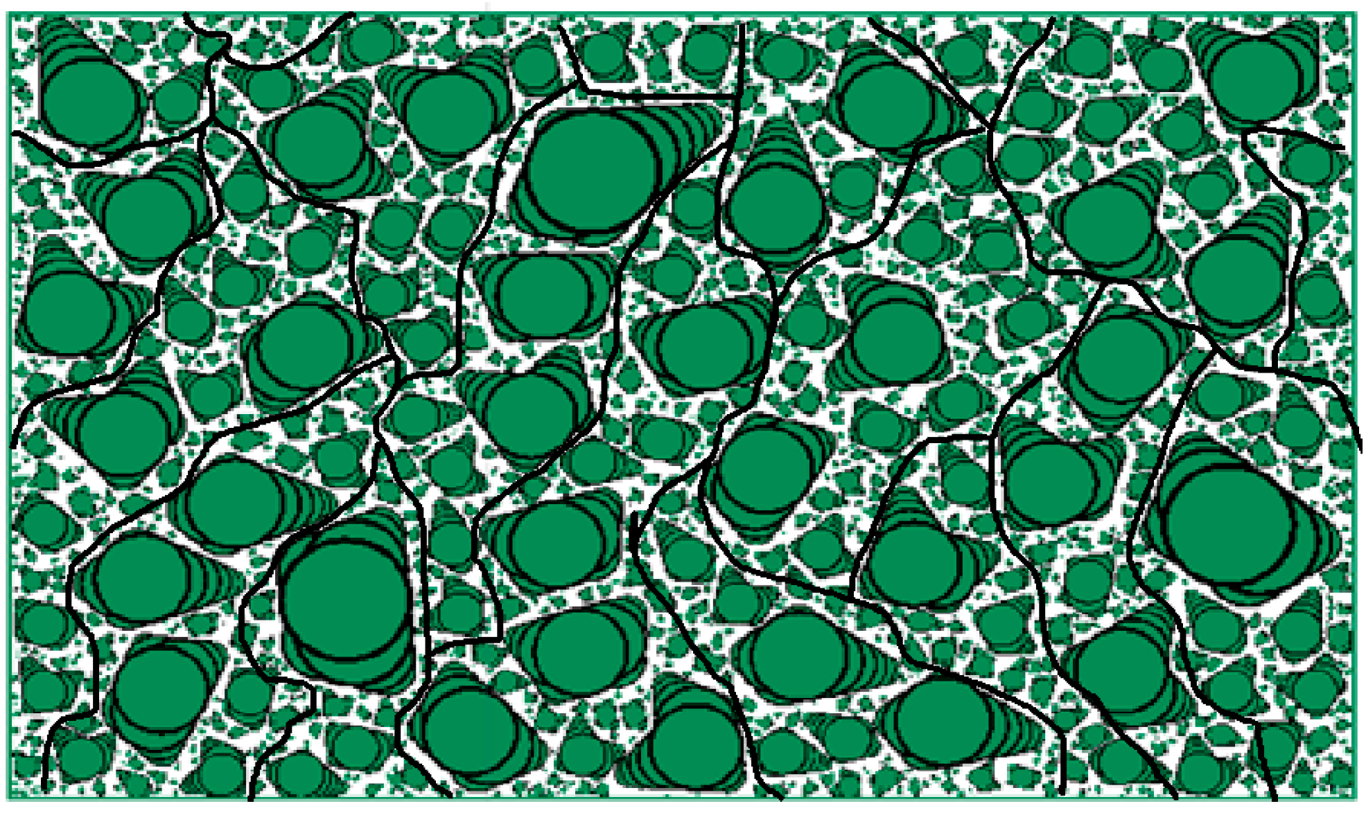
Through PFC2D software, the mixture model of different porosity is generated, and the cross section of the model generated is shown in Figure 5.
Through the observation of Figure 5, the following conclusions can be drawn:
  • The number of connected pores in the specimens with high porosity increases significantly, the width of the pores is generally larger, and the length of the pores with large width is also large.
  • The shapes of the pores are different, and there is no rule to speak of, but generally speaking, the width of the pores does not exceed 5 mm, and most of the pore widths are concentrated between 1–4 mm.
  • The specimens with lower porosity also have pores with large widths, but the pores in the dense specimens are mostly not connected due to the high degree of compaction and are invalid pores.
  • In the specimens with large porosity, the contact points between the stones are obviously less than the specimens with low porosity, and the large particles of stones are not completely filled.

3.2. Mesoscopic Simulation Test of Blocking Behavior

A model with 20% porosity was obtained by the PFC software simulation. The template used in the process of simulating siltation was produced in equal proportions. The specific process is as follows:
1. Print out the model drawings of 20% void ratio simulated by PFC in equal proportions, then observe the model drawings, mark the main interconnected and characteristic voids in the drawings, and draw them in equal proportions on a 11 cm × 11 cm square translucent silicone plate. As shown in Figure 6.
2. Use a wallpaper knife to carefully dig out excess silica gel along the direction of the main communication gap, and dig it into a pore structure ranging from 1 mm–4 mm.
3. Dip a little water on the gapped side of the prepared silica gel template and stick it on the transparent glass sheet, and press the other side with a heavy object to make it fit closely to the glass plate.
4. Spread quantitative blockages of each particle size evenly from the upper part of the silica gel plate, and then sprinkle water. The mass ratio of the blockage to the water is 1:50, and observe the blockage of the stones of each particle size.
5. Use the prepared complete set of silted material to simulate the silting process and explore the influence of time on the silting process. Taking 100 g of water as a cycle, after one blockage cycle, the template is placed at room temperature for 12 h, and a total of 10 cycles are performed to observe the blockage.

3.3. Formatting of Mathematical Components

1. According to the designed mixture ratio, three PAC Marshall specimens were made, and the initial weight, porosity and water permeability coefficient of the Marshall specimens in the dry state were measured and recorded, as shown in Table 7.
2. We prepared the sludge according to the set level. The fine aggregate must be dry and fine, free of debris, and not agglomerated, and then fully mixed and dried for the clogging test.
3. We took the annual average rainfall of 600 mL in Changchun as one cycle, and it was determined that the mass of the clogged fine material in each cycle in this experiment was 12 g. The Marshall specimen was placed in the groove of the base, and the nozzle was turned on to adjust the intensity of the water. Then, the water was sprayed in the water tank on the rotating specimen to simulate rainfall. The blockage was divided into five equal parts, which were evenly distributed on the surface of the specimen in each cycle.
4. After completing one cycle, the unplugged plugging agent was collected, dried and weighed to obtain the weight of the plugging agent blocked in the test piece. After drying the specimen, the void ratio and the water permeability coefficient after one cycle of silting were measured.
5. We simulated the rainfall cycle until the specimen was completely blocked, that is, the porosity dropped to 8% or the water permeability dropped to 0.03 cm/s, and the number of cycles at this time was recorded.

3.4. Asphalt Pavement Noise Detection Test

In this test, two common impermeable asphalt mixture grading types AC-13 and SMA-13 and a permeable asphalt mixture grading type PAC-13 were selected to make a standard rut board, and the tire falling method was used. This carried out the tire noise level test. The experimental results were used to compare and analyze the noise level of the drainage pavement and impervious pavement.
The tire falling method simulates the momentary process of the impact of wheels driving on the road, and standard ordinary car tires were used during the test. The researches held the tire and made it fall straight from a height of 650 mm from the ground and collide with various types of mixed material rut boards placed on the ground. The noise meter was placed at a horizontal distance of 800 mm from the impact point and a height of 560 mm to test the noise size. The rut board was a standard rut board rolled and formed by a wheel roller forming machine in the laboratory, with a length of 300 mm, a width of 300 mm and a thickness of 50 mm. The tire pressure was 0.2 N/mm2

3.5. Noise Detection Test before and after Blockage of Permeable Asphalt Pavement

This test mainly explored the change of void ratio before and after road blockage and the change of road noise. The test adopted a pavement thickness of 4 cm, a disc area of 6594 cm2, and a target void ratio of 20%. The tire pressure was 700 kPa.
The experimental device compacted the specimen 35 times, then we placed the specimen at room temperature for 24 h, and finally determined whether the void ratio of the specimen reached the standard. In addition, four points in the cross direction of the disc specimen were taken to measure the thickness of the road surface. The various indexes of the road surface after forming are shown in Table 8.
After the test pavement was completely formed, we evenly spread the blocking agent on the pavement in stages, adding 1000 g of silt each time, and then sprayed an appropriate amount of tap water on the pavement in stages, turned on the rutting tester, and let the wheels roll over the pavement. The purpose was to simulate the actual driving process and accelerate road blockages. After the silting agent had completely entered the pavement and the pavement was air-dried, we performed a noise test. The specific steps were as follows.
  • The gaps in each part of the testing machine were filled with soft and porous sound-absorbing materials in order to reduce the influence of excessive mechanical noise on the experimental results during the operation of the testing machine.
  • The noise meter was connected to the computer with a data cable, and the range was selected automatically (30 dB–130 dB).
  • The sensor of the noise meter was equipped with an anti-interference sponge ball, which was to reduce the interference of wind and human voices in the environment. Then we placed the sensor in a fixed position on the test road, with the sensor head flush with the road.
  • After the experiment started, when the tires were rotating stably, we started the real-time measurement function in the software, and stopped after timing for one minute.
The built-in measurement software of the noise meter has the functions of measuring and analyzing data, and can output multiple sets of data line graphs at the same time, which is convenient for observing data changes. After the pavement was blocked 4 times, no matter how many times it was repeated or the increase of the water flow, the blocking agent could not be completely blocked into the pavement, and only a small part of the small particles of soil material entered the inside. The remaining silt accumulated on the surface of the road, indicating that the road surface had basically lost its water permeability function and was completely blocked.

4. Results and Discussion

4.1. Meso-Analysis of Blocking Behavior

In order to study the movement of blockages and water flow in the process of silting in depth, according to the characteristics of the internal voids of the specimen obtained by the simulation, the vertical section of the specimen was simulated by the silica gel plate. Then, the silica gel plate was sprinkled with stones and washed by water to simulate the siltation of the permeable pavement from a meso level. The following conclusions were obtained through simulation experiments.

4.1.1. Simulation of the Influence of Each Particle Size on the Blocking Process of Asphalt Mixture

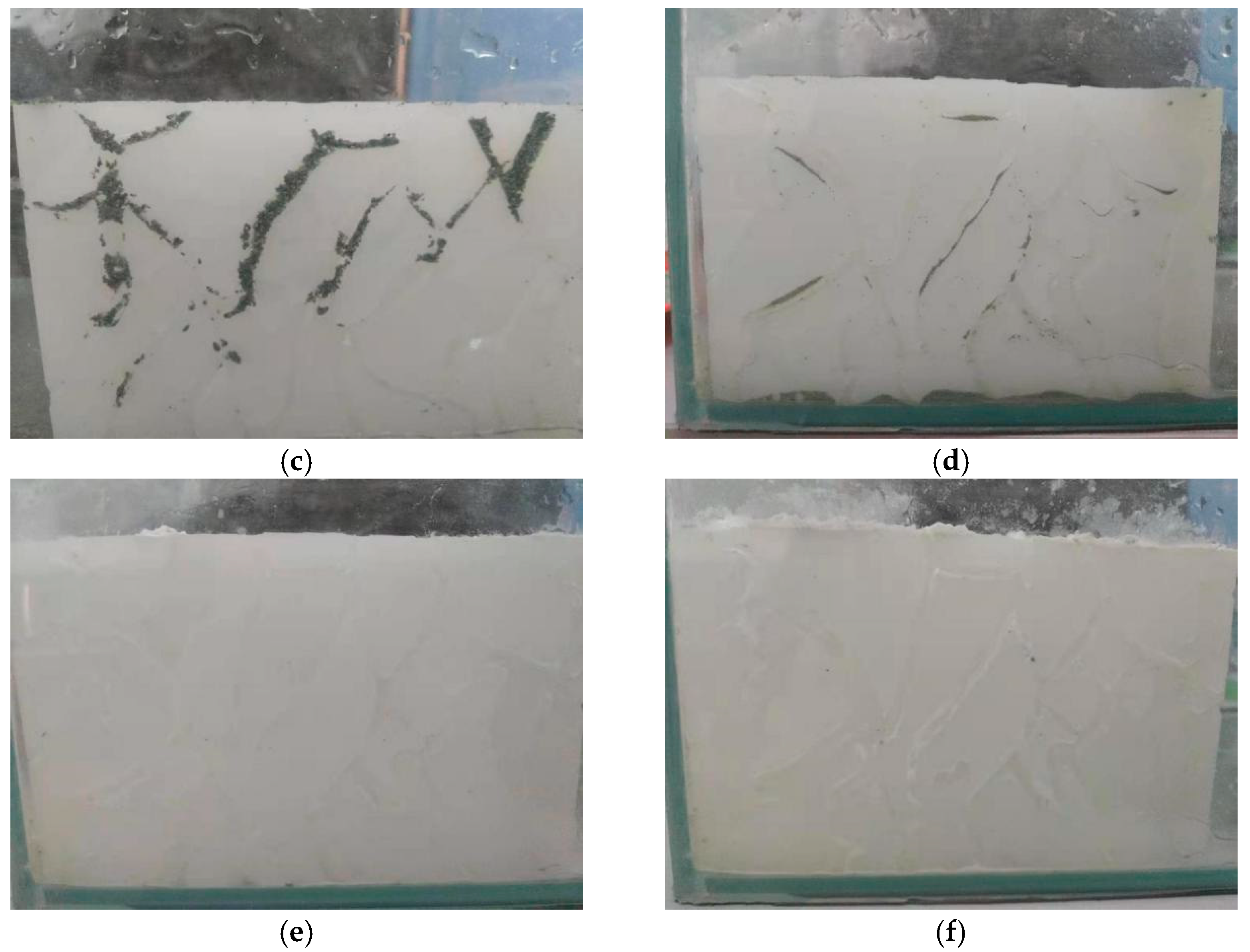
This separately blocked stones of various particle sizes. The total mass of the sludge was 2 g and the water mass was 100 g in each slugging cycle, and the cycle was 10 times. We carried out the experiment and carefully observed the blockage process of each group, as shown in Figure 7.
As can be seen in Figure 7, when each particle size acts alone, the blockage of 0.3 ~0.6 mm stones is the most serious. Small particles below 0.15 mm cannot block the layout when they act alone, and the particle size above 1.18 mm can hardly enter the road surface. Therefore, the critical particle size for clogging is 0.3–0.6 mm. When the full-graded silt is mixed, the small-particle stones will absorb each other in the depths of the road surface after the large-sized stone blocks the main gaps through the action of water flow, and they will form stubborn obstructions, and the silt will move laterally under the action of water flow.

4.1.2. Analysis of Blockage of Full-Graded Blockage

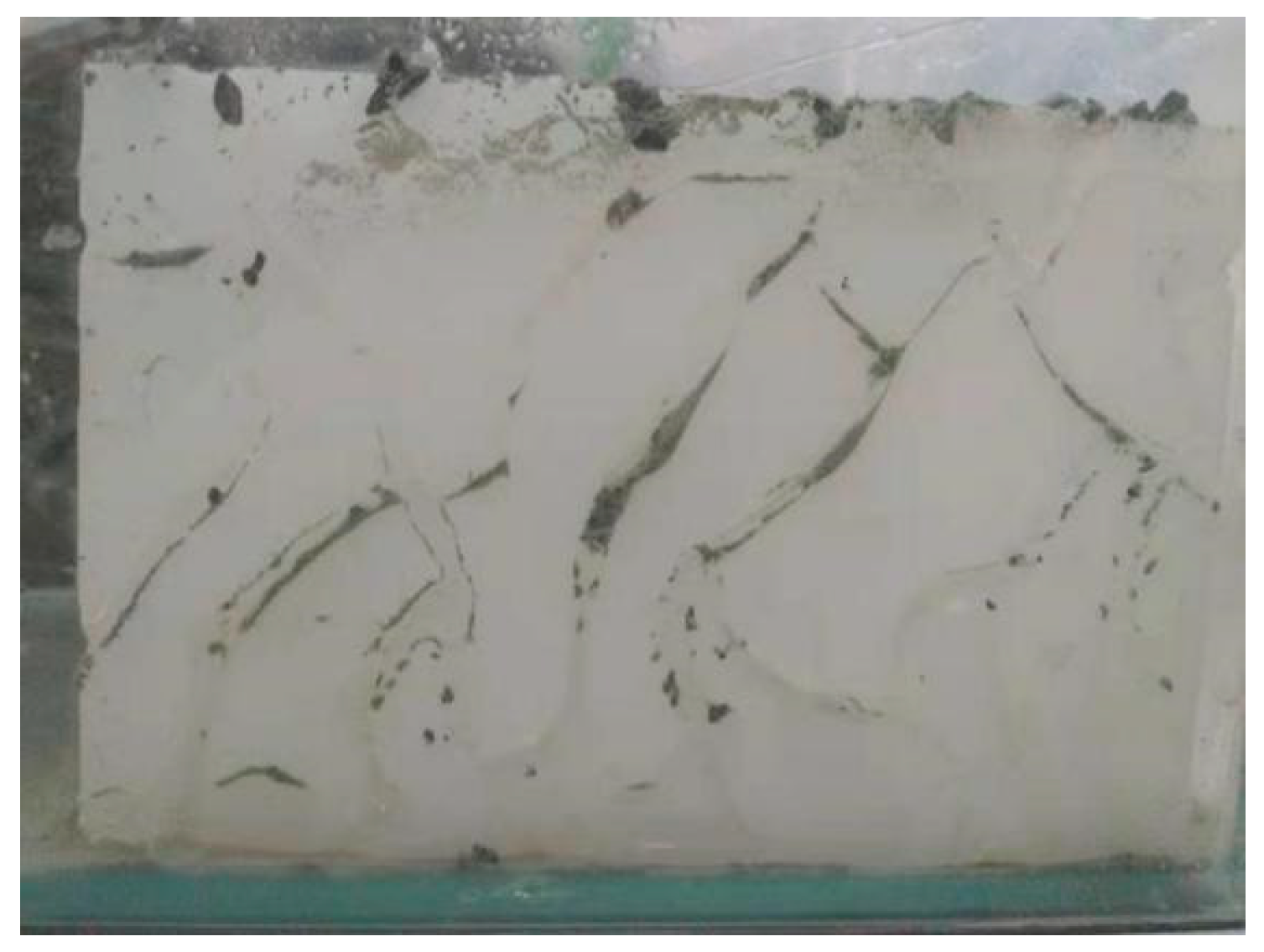
According to the selected blockage grading, it was made into a full-size blockage for the blockage test. In each blockage cycle, the total mass of the blockage was 2 g, the water mass 100 g, and each set of cycles was 10 times. We carried out tests and carefully observed the silting process of each group. The blockage of the full-graded blockage is shown in Figure 8.
By observing the blockage area and degree of blockage, it was found that the blockage of the full-graded blockage was the most serious and complicated. Large-sized stones were mainly blocked within 2 cm of the upper part of the template, and small-sized stones were blocked in the lower part of the template. Because the upper part was blocked by coarse stones, the water flow became smaller and even unable to penetrate to the lower part. It could not be washed away in the repeated drying and fouling process, forming a blockage. In the blocking process of the full-graded blockage, the small particle size stones accounted for a certain proportion of the overall blockage. The reasons are as follows: first, the upper part of the interconnection gap is blocked by large-size particles, which reduces the flow of water and the scouring force of water; second, larger particles block the void channels and restrict the flow of small particles in the void; third, although the larger-diameter stones do not completely block the voids, they make the gaps narrow and tortuous, leaving the smaller-diameter stones in the pores. In the process of blockage of small particle size blockage, compaction is the main factor. The process is that after the small particle blockages remain in the gap, as the pore water evaporates the blockages begin to dry and compact, and adhere to the walls of the gap channels. After such repeated effects, a consolidation blockage gradually formed, forming a “stubborn blockage”.

4.1.3. The Role of Water Flow

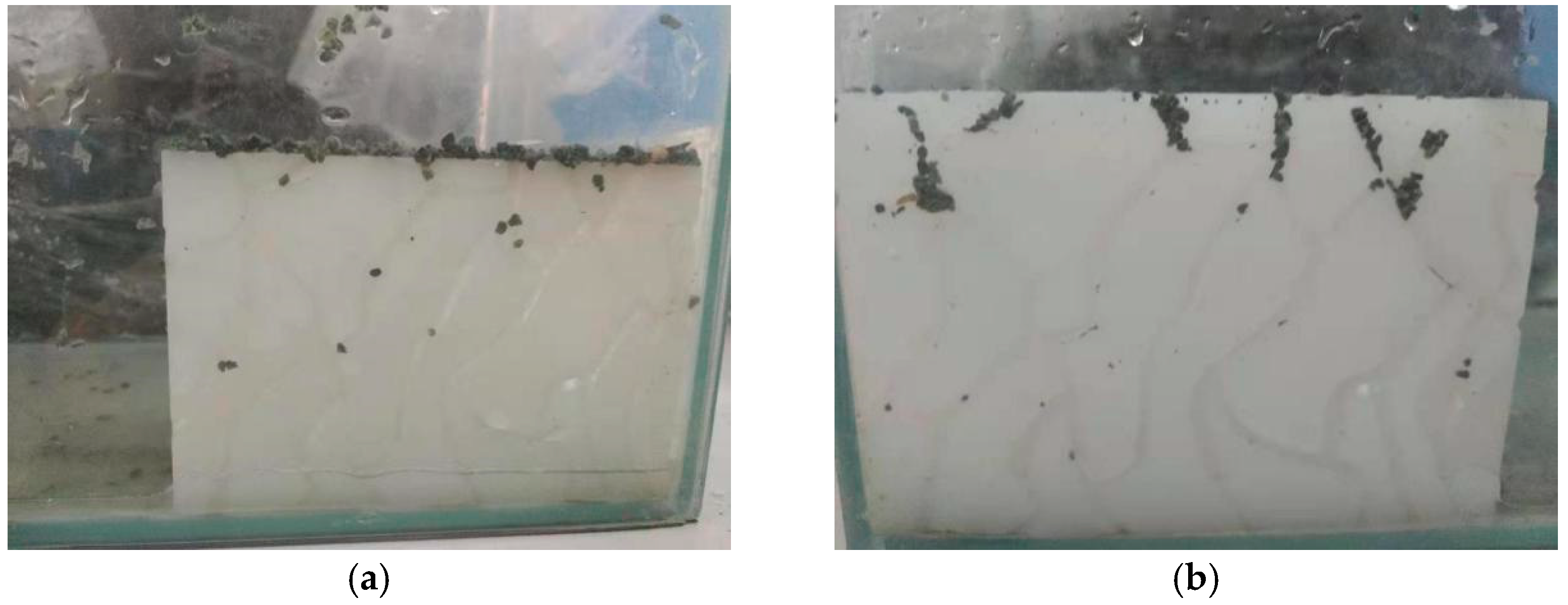
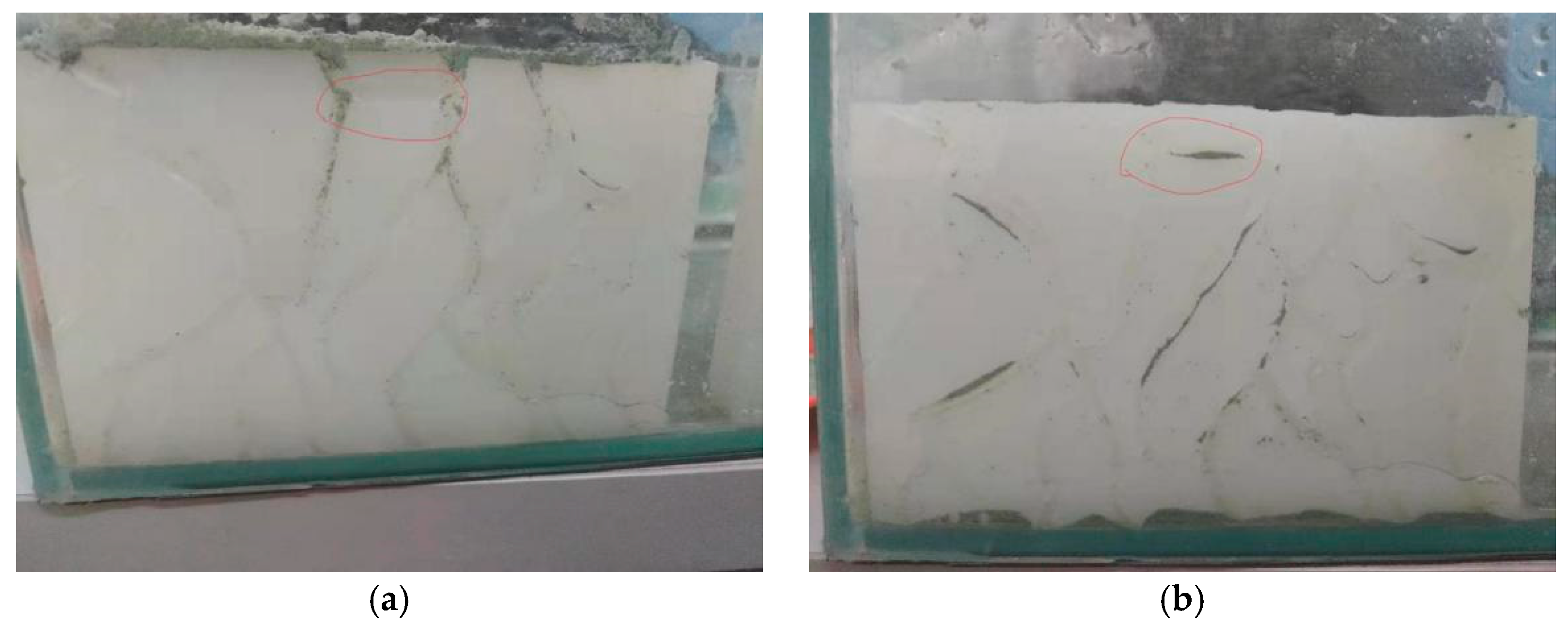
Dry blockages, especially those with small particle size and small mass, will only move downwards under the action of gravity when they enter the template. It will move into the branch gap only after being impacted by water. The specific situation is shown in Figure 9.
As you can see from the picture above, water flow plays an important role in the blockage process. Sometimes it will wash away the blockage and reduce the blockage, sometimes it will aggravate the blockage.

4.1.4. The Three Stages of the Blockage Process

After repeated rain washing and drying cycles, it can be ascertained by observing the template that as the number of clogging cycles increases, the largest clogging occurs in the first three clogging processes. During the subsequent 4–7th blockage process, only local gaps were blocked or washed away by water flow, or continued to be blocked. Finally, after the 8th cycle, the congestion situation remained basically unchanged. In summary, the clogging process can be roughly divided into three parts.
1. Rapid blockage stage. The clogging is the most obvious in the early stage, the fine aggregate is blocked in the lower part of the mold, and the coarse aggregate is blocked in the upper part of the mold. The main reason is that the coarse particles block the upper connecting gap, making the gap width smaller. Most blockages cannot move downwards, only small aggregates can move downwards through narrow gaps. The clogging in this process mainly comes from the clogging effect of the coarse aggregate, which occurs relatively quickly.
2. Slow blockage stage. After the initial clogging is finalized, the rainwater will pass through the narrow void structure to wash away the small clogged large particles and most of the clogged small particles. As a result, a few clogged large particles are loosened, and the shape of the narrow gap changes slightly. The blocked small particles are continuously washed away under the impact of the water flow, and some are deposited in the gaps, turns, and bumps. In the process of repeated drying and scouring, they are hardened together to form a “stubborn blockage”. The clogging in this process mainly comes from the clogging effect of the fine aggregate, and the occurrence process is slow.
3. The final blockage stage. After many clogging cycles, the lower void structure was also blocked by the compacted fine aggregate, and could not be washed away by the water flow. The upper part of the mold is blocked by coarse aggregates, and the lower part is blocked by hardened materials. The blockage is basically shaped.

4.1.5. Location and Depth of Blockage

According to the location of the final blockage, the blockage can be divided into two parts: Shallow clogging on the surface and deep clogging on the inside, and almost no clogging at the bottom of the layout. The main cause of shallow blockage on the surface is coarse-particle blockage. This part of the blockage is within 2 cm of the surface. It forms extremely quickly at the beginning of the blockage and, after it is formed, it is not easily washed away by water, and basically no longer moves. The main cause of deep internal blockage is small particle-sized sludge. This part of the blockage passes through the gap after the blockage of the coarse particle size above and gathers at the lower part, within 5 cm from the road surface. Staying at the corner of the gap and gradually gather, some will be washed away and moved and blocked by the water flow. In the repeated drying-wetting process, they harden into a stubborn blockage. In the actual clogging cleaning process, generally only part of the shallow surface clogging can be cleaned by suction, and it is very difficult to clean the deep internal clogging.

4.2. Change in Permeability of Asphalt Mixture During Blockage

The silting process was simulated by using a dynamic water scour instrument, and the test piece was basically completely blocked after 50 cycles. The quality, porosity and water permeability of the test piece basically no longer change, so the data of the first 50 cycles are taken for statistical analysis.

4.2.1. The Quality of Porous Asphalt Concrete (PAC) Marshall Specimens Varies with the Number of Blockages

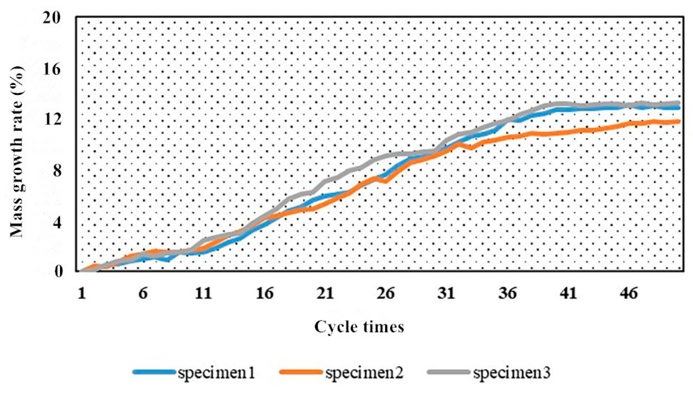
In order to more intuitively see the extent of the increase in the mass of the specimen during the blocking process, the ratio of the increase in the mass of the specimen from the initial mass to the initial mass after each cycle is defined as the mass increase rate. The change in the mass ratio of the sludge during the whole silting process is shown in Figure 10.
It can be seen from Figure 10 that although the initial quality of the three specimens is different, the trend of their quality increasing as the number of cycles increases is the same, which can be divided into three stages, namely the high-speed growth stage and the slow growth stage, and the final stage of equilibrium. At the end of the silting, the mass of the specimen increased by about 13% compared to the initial mass.

4.2.2. The Porosity of the PAC Marshall Specimen Varies with the Number of Blockages

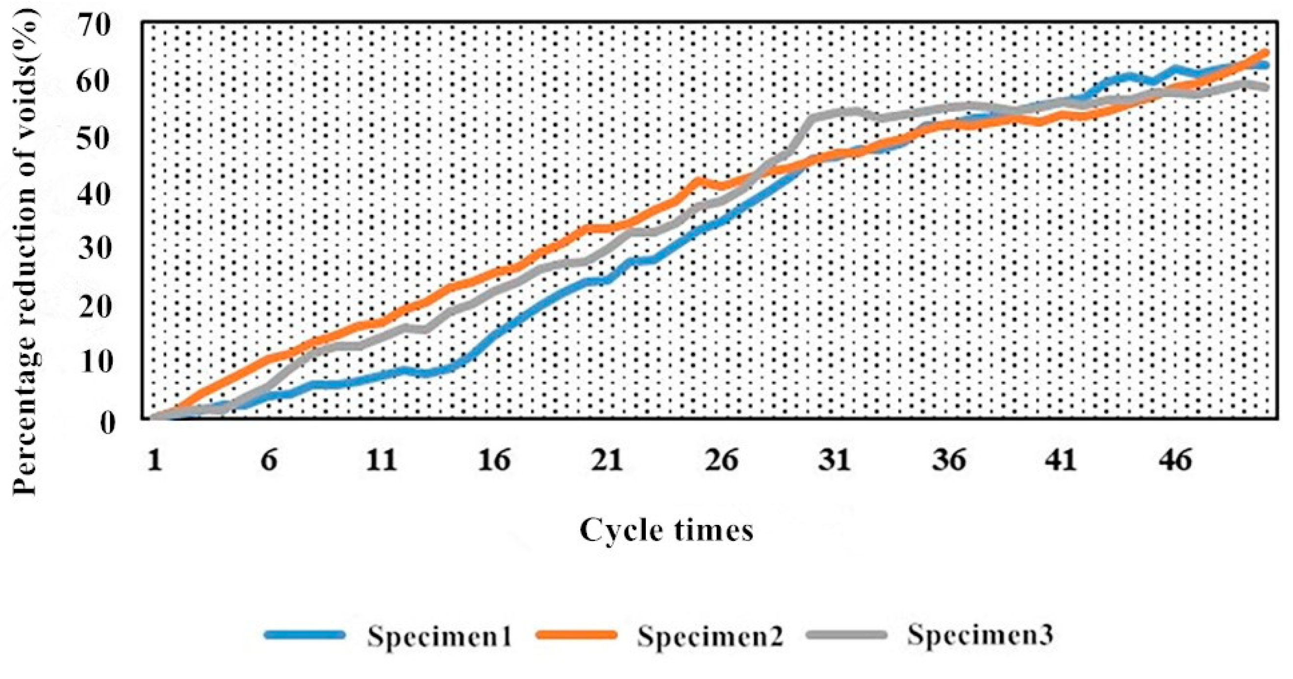
Similarly, the ratio of the reduction of the void ratio of the test piece after each cycle to the initial void ratio is defined as the reduction of the void ratio. In order to more intuitively describe the trend of void rate reduction during the silting process, the void rate reduction rate in the whole process is plotted as a line graph, as shown in Figure 11.
It can be seen from Figure 10 and Figure 11 that the porosity of the test piece gradually decreases with the increase in the number of siltings, and the decrease is similar to the change in the quality of the test piece, both from a large change to a flattening, and corresponding to the silting process. The porosity of the test piece dropped from about 20% at the beginning to about 8%, which basically meant a loss of the water permeability function.

4.2.3. The Variation of the Permeability Coefficient of the PAC Marshall Specimen with the Number of Blockages

Similarly, calculate the loss rate of the water permeability coefficient of the test piece, as shown in Figure 12.
By observing the line graph of the loss rate of the permeability coefficient, it can be easily seen that the attenuation trend of the permeability coefficient is also in line with the overall silting process. The change trend of the permeability coefficient loss rate is first large, then small, and finally stabilized. The final permeability coefficient is reduced to about 0.07 cm/s, and the permeability function only retains less than 20% of the initial value, and the permeability function is basically lost.
The blockage process simulation of the permeable Marshall specimen in the laboratory was used to explore the changes in the weight, porosity and permeability coefficient of the specimen during the blockage. The three indicators can reflect to a certain extent the changes in the permeability of the permeable pavement during the blockage process. The above three indicators are only suitable for the simple evaluation of the blockage of the specimen in the indoor test.

4.3. Analysis of Noise Reduction Effect of Permeable Asphalt Pavement

Through the tire drop test, the tire noise level of the rut plates of the three gradation asphalt pavements of ordinary densely configured AC-13(Asphalt concrete with a nominal particle size of up to 13 mm), SMA(Stone Mastic Asphalt) and permeable asphalt pavement PAC-13(Fine-grained permeable asphalt concrete) was tested. The results are shown in Table 9.
It can be seen from Table 9 that the noise of the common densely equipped AC-13 and SMA tires tested by the tire drop method is almost the same. The tire noise of the permeable PAC-13 rut board is significantly lower than the first two. This is due to the large internal voids in the permeable asphalt pavement. When the tire hits the road, the compression of the air at the contact point is lower than that of the densely distributed road, and the noise produced is less than that of the dense road. It can be seen that, compared with ordinary pavement, permeable asphalt pavement does have a good noise reduction effect.

4.4. Noise Analysis before and after Blockage of Permeable Asphalt Pavement

The rutting tester and noise meter are used to test the change of the road noise during the silting process of the PAC-13 asphalt pavement, and record the value of the road noise after each silting is completed, as shown in Table 10.
From the data in the table, it can be seen that the noise reduction effect of the permeable pavement is significantly reduced after being blocked. As the degree of congestion deepens, road noise gradually increases. The noise of the heavily congested road is about 4 dB higher than that of the road before it is not congested. In order to more intuitively observe the relationship between the change in noise and the change in quality, the ratio of the noise increase value to the initial value is defined as the noise increase rate, and it is plotted with the quality growth rate in a unified line graph, as shown in Figure 13.
As can be seen from the broken line graph, the noise reduction effect of the permeable pavement gradually decreases as the road surface is gradually blocked when it is put into use. There is a certain quantitative relationship between the size change of road noise and the degree of road blockage. Therefore, the degree of blockage of the permeable road can be detected according to the change of the noise level of the road. We quantitatively evaluated the blockage of the road surface to achieve the goal of non-destructive and accurate detection of blockage.

5. Conclusions

In this paper, the silting behavior of a permeable pavement was simulated in detail, and the permeable performance of the permeable Marshall specimen during the silting process was studied. The relationship between the noise and the degree of congestion on the permeable pavement was then explored, and a method of non-destructive detection of the degree of congestion on the road was proposed. Finally, we summarized several current methods of cleaning permeable pavement, evaluated several new cleaning methods, and put forward some suggestions on the protection of permeable pavement blockage. The main conclusions of this article are as follows:
  • Through the mesoscopic simulation process of blocking behavior, it was found that: the clogging process can be roughly divided into three stages, (1) early fast clogging stage, (2) middle slow clogging stage, (3) terminal clogging stable stage. According to the position of the blockage, it can be divided into shallow blockage on the surface and deep blockage on the inside. The role of water flow in the blockage process cannot be ignored. It is the main factor that promotes the lateral movement of the blockage, sometimes promoting blockage and sometimes slowing it down.
  • The critical particle size of the blockage is particles within 0.3–0.6 mm. Particles above 1.18 mm gather on the road surface and it is difficult for them to enter the road surface. The particles below 0.03 mm are basically washed away by the water flow and cannot form a large blockage. Therefore, when cleaning the blockage of the permeable asphalt pavement, the 0.3–0.6 mm particles should be considered.
  • The simulated blockage test of the PAC-13 Marshall specimen found that: during the clogging process, the weight, porosity, and water permeability of the test piece became larger as the degree of clogging deepened, and the range of change was first large and then small. This shows that the early blockage occupies a larger proportion.
  • The tire drop test in the laboratory verified that the permeable asphalt pavement had better noise reduction performance than the ordinary densely distributed pavement.
  • According to the noise change in the process of indoor simulation of road blockage, a new method of non-destructive detection of permeable road blockage is proposed.

Author Contributions

Conceptualization, X.G.; software, S.C.; formal analysis, S.C.; investigation, X.L. and C.Z.; data curation, S.C., W.C. and X.L.; writing—original draft preparation, S.C.; writing—review and editing, X.G.; project administration, X.G. All authors have read and agreed to the published version of the manuscript.

Funding

This research was funded by the Jilin Province Science and Technology Development Plan (CN) (Grant No. 20190303033SF).

Institutional Review Board Statement

Not applicable.

Informed Consent Statement

Not applicable.

Acknowledgments

This research was funded by the Jilin Provincial Science and Technology Development Program (CN) (Grant No. 20190303033SF). This financial support is gratefully acknowledged.

Conflicts of Interest

The authors declare that there is no conflict of interests regarding the publication of this paper.

References

  1. Liu, Y.; Cheng, X.; Yang, Z. Effect of Mixture Design Parameters of Stone Mastic Asphalt Pavement on Its Skid Resistance. Appl. Sci. 2019, 9, 5171. [Google Scholar] [CrossRef] [Green Version]
  2. Pérez-Acebo, H.; Gonzalo-Orden, H.; Findley, D.J.; Rojí, E. A skid resistance prediction model for an entire road network. Constr. Build. Mater. 2020, 262, 120041. [Google Scholar] [CrossRef]
  3. Ma, X.; Wang, H.; Zhou, P. Novel Gradation Design of Porous Asphalt Concrete with Balanced Functional and Structural Performances. Appl. Sci. 2020, 10, 7019. [Google Scholar] [CrossRef]
  4. Volder, A.; Watson, T.; Viswanathan, B. Potential use of pervious concrete for maintaining existing mature trees during and after urban development. Urban For. Urban Green. 2009, 8, 249–256. [Google Scholar] [CrossRef]
  5. Fassman, E.; Blackbourn, S. Urban Runoff Mitigation by a Permeable Pavement System over Impermeable Soils. J. Hydrol. Eng. 2010, 15, 475–485. [Google Scholar] [CrossRef]
  6. Gilbert, J.K.; Clausen, J.C. Stormwater runoff quality and quantity from asphalt, paver, and crushed stone driveways in Connecticut. Water Res. 2006, 40, 826–832. [Google Scholar] [CrossRef]
  7. Gomez-Ullate, E.; Castillo-Lopez, E.; Castro-Fresno, D.; Bayon, J.R. Analysis and Contrast of Different Pervious Pavements for Management of Storm-Water in a Parking Area in Northern Spain. Water Resour. Manag. 2010, 25, 1525–1535. [Google Scholar] [CrossRef]
  8. Hibbs, B.J.; Sharp, J.J.M. Hydrogeological Impacts of Urbanization. Environ. Eng. Geosci. 2012, 18, 3–24. [Google Scholar] [CrossRef]
  9. Imran, H.; Akib, S.; Karim, M.R. Permeable pavement and stormwater management systems: A review. Environ. Technol. 2013, 34, 2649–2656. [Google Scholar] [CrossRef] [Green Version]
  10. Kuruppu, U.; Rahman, A.; Rahman, M.A. Permeable pavement as a stormwater best management practice: A review and discussion. Environ. Earth Sci. 2019, 78, 327. [Google Scholar] [CrossRef]
  11. Roseen, R.M.; Ballestero, T.P.; Houle, J.J.; Briggs, J.F.; Houle, K.M. Water Quality and Hydrologic Performance of a Porous Asphalt Pavement as a Storm-Water Treatment Strategy in a Cold Climate. J. Environ. Eng. 2012, 138, 81–89. [Google Scholar] [CrossRef]
  12. Scholz, M.; Grabowiecki, P. Review of permeable pavement systems. Build. Environ. 2007, 42, 3830–3836. [Google Scholar] [CrossRef]
  13. Wilson, C.E.; Hunt, W.F.; Winston, R.J.; Smith, P. Comparison of Runoff Quality and Quantity from a Commercial Low-Impact and Conventional Development in Raleigh, North Carolina. J. Environ. Eng. 2015, 141, 05014005. [Google Scholar] [CrossRef]
  14. Mampearachchi, W.; Masakorala, S.; Umasangar, K. Aggregate interlocking of open-graded friction courses with compaction effort. J. Natl. Sci. Found. Sri Lanka 2019, 47, 139. [Google Scholar] [CrossRef]
  15. Dai, Z.; Shen, J.; Shi, P.; Zhu, H.; Li, X. Nano-sized morphology of asphalt components separated from weathered asphalt binders. Constr. Build. Mater. 2018, 182, 588–596. [Google Scholar] [CrossRef]
  16. Chen, J.; Yin, X.; Sha, A.; Ding, Y. Evaluation of durability and functional performance of porous polyurethane mixture in porous pavement. J. Clean. Prod. 2018, 188, 12–19. [Google Scholar] [CrossRef]
  17. Luo, S.; Qian, Z.-D.; Xue, Y.-C. Performance evaluation of open-graded epoxy asphalt concrete with two nominal maximum aggregate sizes. J. Cent. South Univ. 2015, 22, 4483–4489. [Google Scholar] [CrossRef]
  18. Chui, T.F.M.; Liu, X.; Zhan, W. Assessing cost-effectiveness of specific LID practice designs in response to large storm events. J. Hydrol. 2016, 533, 353–364. [Google Scholar] [CrossRef]
  19. Zhao, X.; Yang, Y. Research on Permeable Pavement Void Characteristics under Sponge City Thinking. Highw. Traffic Technol. 2016, 5, 192–193. [Google Scholar]
  20. Elvik, R.; Greibe, P. Road safety effects of porous asphalt: A systematic review of evaluation studies. Accid. Anal. Prev. 2005, 37, 515–522. [Google Scholar] [CrossRef]
  21. Coughlin, J.P.; Campbell, C.D.; Mays, D.C. Infiltration and Clogging by Sand and Clay in a Pervious Concrete Pavement System. J. Hydrol. Eng. 2012, 17, 68–73. [Google Scholar] [CrossRef]
  22. Deo, O.; Sumanasooriya, M.; Neithalath, N. Permeability Reduction in Pervious Concretes due to Clogging: Experiments and Modeling. J. Mater. Civ. Eng. 2010, 22, 741–751. [Google Scholar] [CrossRef]
  23. Nguyen, D.H.; Boutouil, M.; Sebaibi, N.; Baraud, F.; Leleyter, L. Durability of pervious concrete using crushed seashells. Constr. Build. Mater. 2017, 135, 137–150. [Google Scholar] [CrossRef]
  24. Chopra, M.; Kakuturu, S.; Ballock, C.; Spence, J.; Wanielista, M. Effect of Rejuvenation Methods on the Infiltration Rates of Pervious Concrete Pavements. J. Hydrol. Eng. 2010, 15, 426–433. [Google Scholar] [CrossRef]
  25. Guan, Y. Research on Water Permeability Mechanism and Structure Design of Macroporous Asphalt Pavement; Beijing Jiaotong University: Beijing, China, 2008. [Google Scholar]
  26. Sun, H. Design of Permeable Asphalt Pavement Structure Layer Based on Heavy Metal Control; Nanjing Forestry University: Nanjing, China, 2014. [Google Scholar]
  27. Kang, A.; Xu, X.; Kou, C. Experimental study on void blocking of permeable asphalt mixture based on improved testing method. Road Constr. 2017, 5, 102–105. [Google Scholar]
  28. Montes, F.; Haselbach, L. Measuring Hydraulic Conductivity in Pervious Concrete. Environ. Eng. Sci. 2006, 23, 960–969. [Google Scholar] [CrossRef]
  29. Kia, A.; Wong, H.S.; Cheeseman, C. Clogging in permeable concrete: A review. J. Environ. Manag. 2017, 193, 221–233. [Google Scholar] [CrossRef]
  30. Lyons, K.R.; Putman, B.J. Laboratory evaluation of stabilizing methods for porous asphalt mixtures. Constr. Build. Mater. 2013, 49, 772–780. [Google Scholar] [CrossRef]
  31. Vancura, M.E.; Macdonald, K.; Khazanovich, L. Location and Depth of Pervious Concrete Clogging Material before and after Void Maintenance with Common Municipal Utility Vehicles. J. Transp. Eng. 2012, 138, 332–338. [Google Scholar] [CrossRef]
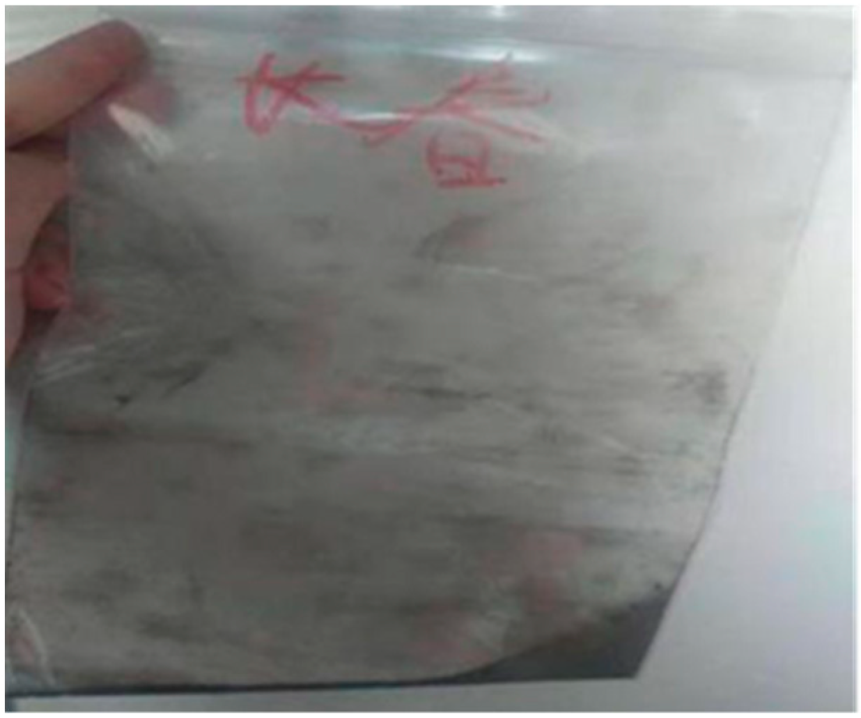
Figure 1. Blockage sample.
Applsci 11 00349 g001
Figure 2. (a) The structure diagram of the dynamic water scour instrument. (b) The dynamic water scour instrument.
Applsci 11 00349 g002
Figure 3. (a) Schematic diagram of the new rutting tester. (b) Physical image of the new rutting test. ① disc; ② bracket at the lower part of the disc; ③ driving wheel frame device; ④ counterweight; ⑤ reduction gear; ⑥ transmission shaft; ⑦ cantilever bracket; ⑧ rotating shaft; ⑨ heating device; ⑩ controller.
Applsci 11 00349 g003
Figure 4. The resulting particle mode.
Applsci 11 00349 g004
Figure 5. (a) Mixture model with porosity 25%. (b) Mixture model with porosity of 20% (c)Mixture model with porosity of 10%.
Applsci 11 00349 g005
Figure 6. The model’s main interconnection gaps.
Applsci 11 00349 g006
Figure 7. (a) 1.18 mm particle size or more (b) 0.6 mm–1.18 mm particle size. (c) 0.3 mm–0.6 mm particle size (d) 0.15 mm~0.3 mm particle size. (e) 0.075 mm~0.15 mm particle size (f) 0.075 mm or less particle size.
Applsci 11 00349 g007aApplsci 11 00349 g007b
Figure 8. Blockage of full-graded blockage.
Applsci 11 00349 g008
Figure 9. (a) Blockage with dry blockage. (b) Blockage with impact of water flow.
Applsci 11 00349 g009
Figure 10. Variation of test piece quality growth rate with number of cycles.
Applsci 11 00349 g010
Figure 11. The change of void ratio reduction rate with the number of clogging cycles.
Applsci 11 00349 g011
Figure 12. The change of the water permeability coefficient loss rate with the number of clogging cycles.
Applsci 11 00349 g012
Figure 13. Noise growth rate and quality growth rate.
Applsci 11 00349 g013
Table 1. Coarse aggregate properties and technical requirements.
Test ItemsUnitRequired ValueTest Results
Stone crushing Value%≤2621.2
Los angeles abrasion loss%≤3025
Apparent densityg/cm3≥2.602.79
Water absorption%≤2.00.61
Asphalt adhesiongrade≥56
Robustness%≤1210
Needle-like particle content (mixture)
The particle size is greater than 4.75 m m
Particle size 2.36 m m ~4.75 m m
%≤149.3
%≤106
%≤1812
Aggregate larger than 4.75 m m is obtained after washing method <0.075 m m particle content%≤1.00.6
2.36 m m ~4.75 m m aggregates obtained after washing method <0.075 m m particle content%≤3.02.1
Soft stone content%≤32
Table 2. Properties and technical requirements of SBS modified asphalt.
Pilot ProjectsUnitRequired ValueMeasured ValueTest ProcedureRemarks
Penetration 25 °C0.1 mm≥4056T0604qualified
Softening Point°C≥8085T0606qualified
Ductility 15 °Ccm≥8081.4T0605qualified
Ductility 5 °Ccm≥3033T0605qualified
Dynamic viscosity at 60 °C P a s ≥20,000101,000T0620qualified
Viscosity N m ≥2022T0624qualified
Toughness N m ≥1518T0624qualified
Film heating penetration ratio%≥6572.3T0609qualified
Loss of film heating quality%≤0.60.22T0609qualified
Table 3. Proportion of chemical elements in silt.
Element NameContent (%)Element NameContent (%)
O60.960Ca7.450
Na1.475Ti0.487
Mg1.158Mn0.068
Al4.819Fe3.400
Si17.675Zn0.041
P0.099Sr0.017
S0.279Zr0.018
Cl0.159Ba0.113
K1.770Pb0.012
Table 4. Blockage grading table.
Particle Size<0.0750.075–0.150.15–0.30.3–0.60.6–1.181.18–2.36
Proportion2321242174
Table 5. Online digital noise meter parameters.
Measuring Range30–130 dB
Frequency Response31.5–8500 Hz
Accuracy ± 1.5 dB
Resolution0.1 dB
Measuring Gear30–80, 50–100, 60–110, 80–130, 30–130
Dynamic Range50/100 dB
Frequency Weighting CharacteristicsA/C The characteristics of noise that humans can hear and mechanical noise
Sampling Rate20 Times/sec
Dynamic CharacteristicsFAST/SLOW
Working Voltage6 V
Table 6. Mineral Grading.
Mesh   Size   ( m m ) 1613.29.54.752.361.180.60.30.150.075
Gradation1009665141310865.54.5
Table 7. Initial indicators of porous asphalt concrete (PAC)-graded Marshall specimens.
Specimen NumberInitial Dry Weight (g)Initial Void Ratio (%)Initial Permeability Coefficient (cm/s)
1121722.30.27
2125320.90.23
3120021.20.25
Table 8. Simulated pavement properties.
PointThickness (cm)Void Ratio (%)
14.119.8
24.0
34.2
43.9
Table 9. Tire noise of various types of mixture.
Type of RutNoise (dB)Average Value (dB)
AC-13
SMA
PAC-13
81.0
80.6
78.0
80.2
79.8
79.1
80.3
79.9
78.4
80.5
80.1
78.5
Table 10. Noise changes during blockage.
Blocking TimesBlockage Quality (g)Mass Growth Rate (%)Pavement Noise Average (dB)
00074.36
110001.8575.27
210003.7075.98
310005.5677.47
410007.4178.02
54938.3278.46
Publisher’s Note: MDPI stays neutral with regard to jurisdictional claims in published maps and institutional affiliations.